1
Near Field Communication (NFC)
for Mobile Phones
Master of Science Thesis
Erik Rolf & Viktor Nilsson
in cooperation with
Perlos AB
August 2006
Department of Electroscience
Abstract
RFID seems to be a technology without limits for the number of areas it can be used
in. In recent years, the amount of RFID tags has increased rapidly. The technology is
cheap and relatively simple. Most RFID systems are used for logistic purposes,
keeping track of products, vehicles and other material. Some are used for security
purposes like anti theft systems. Tags are also placed in passports, containing
biometric information about the pass holder.
The latest trend within RFID is to use the technology for more advanced applications
that can replace the magnet cards used today for payment and electronic key cards.
The more advanced types of these cards, called proximity cards, have already been
introduced in parts of Asia. The proximity standard was also modified to allow
integration of the technology into cellular phones. This standard, named Near Field
Communication (NFC) can therefore be used to replace key cards and
Visa/Mastercards. At the same time, a small NFC reader integrated in the phone
opens up for many new possibilities. Switching phone numbers with new people can
be done in a quick manner by simple pressing the two cellular phones against each
other. In the same way, Bluetooth connections can be set up without any manual
configuration.
If this idea is accepted by consumers and companies, the cell phone could be the only
device needed when a person leaves the house, since it in addition to being a phone
also is a set of keys, an ID card and a wallet.
Acknowledgements
The authors would like to thank our supervisors Anders Sunesson and Dag
Mårtensson at Perlos AB - Lund, the research and development team at Perlos AB Lund and our supervisor Anders Karlsson at the Department of Electroscience, Lund
Institute of Technology, for all help and guidance throughout this project.
We would also like to thank Kristoffer Nilsson, Digital Illusions - Stockholm for all
help and support with the software development.
We express our gratitude to the companies and distributors who supplied us with free
samples of their products. In particular we thank TDK, Crown Ferrite and NEC/Tokin
for supplying us with μ-materials and ACG for sending us Mifare cards and
transponder chips.
This project was funded and supported by Perlos AB - Lund.
1 Introduction.................................................................................................................1
1.1 Introduction to RFID............................................................................................1
1.1.1 Close coupling systems.................................................................................2
1.1.2 Remote coupling systems .............................................................................2
1.1.3 Long range systems.......................................................................................2
1.1.4 Frequency bands and regulations..................................................................2
2 Applications of RFID and NFC ..................................................................................5
2.1 Identification ........................................................................................................5
2.2 Ticketing ..............................................................................................................6
2.3 Payment................................................................................................................6
2.4 Automation and logistics .....................................................................................8
2.5 NFC applications in cellular phones, computers and personal area networks.....8
2.5.1 Currently existing applications .....................................................................8
2.5.2 Application visions, using NFC to control other connections. .....................8
2.6 Mobile phones......................................................................................................9
2.6.1 Nokia.............................................................................................................9
2.6.2 NTT DoCoMo - Osaifu-Keitai......................................................................9
2.6.3 KDDI – au...................................................................................................11
2.6.4 Vodafone live! FeliCa.................................................................................11
2.6.5 Other manufacturers and trials....................................................................11
3 Electromagnetism and radio circuits.........................................................................12
3.1 Magnetic flux density ........................................................................................12
3.2 Magnetic field strength ......................................................................................12
3.3 Inductance ..........................................................................................................14
3.4 Mutual inductance..............................................................................................14
3.5 Coupling coefficient...........................................................................................15
3.6 Faraday’s law .....................................................................................................15
3.7 Resonance circuits .............................................................................................16
3.8 Power supply......................................................................................................17
4 Data Transfer ............................................................................................................18
4.1 Modulation.........................................................................................................18
4.1.1 Load modulation .........................................................................................18
4.1.2 Backscatter modulation...............................................................................19
4.2 Modulation with subcarrier................................................................................20
4.2.1 ASK.............................................................................................................20
4.2.2 FSK .............................................................................................................20
4.2.3 PSK .............................................................................................................21
4.3 Transmission modes...........................................................................................21
5 Antennas ...................................................................................................................22
5.1 Antennas for close and remote couple systems .................................................22
5.1.1 Antenna coil properties ...............................................................................23
5.2 Antennas for long range systems .......................................................................24
5.3 Placing antennas in metal environments............................................................25
5.3.1 Waveguide materials...................................................................................26
6 NFC – Near Field Communication ...........................................................................28
6.1 The RF specifications ........................................................................................28
6.2 Modulation and data transfer .............................................................................28
6.2.1 Active communication mode ......................................................................28
6.2.1.1 Bit rate 106 kbps ..................................................................................28
6.2.1.2 Bit representation and coding ..............................................................29
6.2.1.3 Bit rate 212 kbps and 424 kbps............................................................29
6.2.1.4 Bit representation and coding ..............................................................30
6.2.2 Passive communication mode.....................................................................30
6.2.2.1 Target to initiator, bit rate 106 kbps.....................................................31
6.2.2.2 Target to initiator, bit rate 212 kbps and 424 kbps ..............................31
6.3 NFC protocols....................................................................................................31
6.3.1 Collision avoidance.....................................................................................32
6.3.2 Initialisation and Single device detection (SDD) for 106 kbps – passive
mode.....................................................................................................................33
6.3.2.1 Frame response time (FRT) .................................................................33
6.3.2.2 Target states .........................................................................................33
6.3.2.3 Frames..................................................................................................34
6.3.2.4 The single device detection (SDD) algorithm .....................................35
6.3.3 Initialisation and SDD for 212 kbps and 424 kbps – passive mode ...........36
6.3.3.1 SDD for 212 kbps and 424 kbps ..........................................................36
6.3.4 Initialisation for 106 kbps, 212 kbps and 424 kbps – active mode.............36
6.4 NFC test parameters and procedures .................................................................37
6.4.1 Test parameters ...........................................................................................37
6.4.2 Test assembly..............................................................................................37
6.4.3 Calibration coil............................................................................................38
6.4.4 Sense coil ....................................................................................................39
6.4.5 Field generating antenna .............................................................................39
6.4.6 Impedance matching network .....................................................................40
6.4.7 Reference devices .......................................................................................41
6.4.7.1 Reference device antenna coil .............................................................41
6.4.7.2 Reference circuit for initiator power test .............................................42
6.4.7.3 Reference circuit for load modulation test...........................................42
6.4.8 Test procedures ...........................................................................................43
6.4.8.1 Target RF level detection.....................................................................43
6.4.8.2 Target passive communication mode...................................................44
6.4.8.3 Target active communication mode.....................................................45
6.4.8.4 Functional test – initiator .....................................................................45
6.4.8.5 Initiator modulation index and waveform in active and passive
communication.................................................................................................45
6.4.8.6 Initiator load modulation reception in passive communication mode .46
7 Test assembly, construction and components...........................................................47
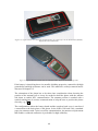
7.1 Reader ................................................................................................................47
7.2 Field generating antenna and impedance matching ...........................................47
7.3 Sense coils and balance circuit ..........................................................................48
7.4 Mounting of the assembly..................................................................................48
7.5 Initial testing ......................................................................................................49
7.6 Signalling and modulation verification..............................................................49
7.7 Development kit.................................................................................................50
7.7.1 MF RD700 Pegoda reader ..........................................................................51
7.7.2 Mifare proximity card .................................................................................51
8 NFC transponder antennas........................................................................................54
8.1 Characteristics of different coils ........................................................................56
8.2 Test of reading range when using waveguide material......................................58
8.3 Mutual inductance between initiator and target antennas..................................64
8.3.1 Dimensions and design of test antenna.......................................................64
8.3.2 Plots and measures of antenna behaviour ...................................................65
9 Integration of NFC in cellular phones ......................................................................67
9.1 Initial testing ......................................................................................................67
9.1.1 NFC antenna coil placement.......................................................................67
9.1.2 Model specific antenna design....................................................................69
9.1.3 Motorola A925............................................................................................69
9.1.4 Nokia 6280..................................................................................................71
9.1.5 Samsung X460 ............................................................................................73
9.1.6 Sony Ericsson K750i...................................................................................74
9.1.7 Sony Ericsson T65 ......................................................................................75
9.1.8 Sony Ericsson Z1010 ..................................................................................76
9.1.9 Nokia 3220..................................................................................................77
9.1.10 Nokia 5140................................................................................................78
9.2 Testing of integrated NFC circuits.....................................................................80
9.2.1 Testing of passive target circuits.................................................................80
9.2.1.1 Target passive communication mode at 106 kbps ...............................80
9.2.1.2 Range and operational volume.............................................................82
9.2.2 Testing of initiator circuits..........................................................................83
9.2.2.1 Target RF level detection (anticollision) .............................................83
9.2.2.2 Initiator field strength in passive communication mode......................84
9.2.2.3 Initiator modulation index and waveform in passive communication
mode.................................................................................................................86
9.3 Measurements in an anechoic chamber .............................................................88
9.3.1 Effects on NFC antenna coil placement......................................................88
9.3.2 Performance degradation results.................................................................89
10 Software ..................................................................................................................92
10.1 Commands .......................................................................................................92
10.2 Developed test assembly software ...................................................................93
10.3 Developed demo application software.............................................................94
10.3.1 Reading / writing Mifare chips .................................................................94
10.3.2 Data type ...................................................................................................95
10.3.3 Reading / Writing binary files...................................................................96
10.3.4 Fetching web link from chip .....................................................................97
10.3.5 File Index ..................................................................................................97
10.3.6 Encrypting / Decrypting data using NFC for key storage.........................98
11 Conclusions...........................................................................................................102
Appendix 1 – Source code .........................................................................................103
A1.1 Stringhandler(.c / .h) .....................................................................................103
A1.2 Filehandler (.h / .c)........................................................................................112
A1.3 Process.c........................................................................................................116
A1.4 Krypt.c...........................................................................................................117
A1.5 QuickCrypt.h.................................................................................................120
A1.6 Rges.c............................................................................................................127
A1.6.1 Main part in demo applications..............................................................142
A1.6.2 Main part in test software.......................................................................145
A1.6.3 Main part in fetch web link ....................................................................146
A1.6.4 Main part in krypto ................................................................................147
Appendix 2 – Demo application examples and manual.............................................148
Appendix 3 – User Manual for NFC test assembly ...................................................151
A3.1 Calibration of the test assembly ....................................................................151
A3.2 Trig the oscilloscope .....................................................................................152
A3.3 Using the assembly for testing ......................................................................153
A3.3.1 Target load modulation test....................................................................153
A3.3.2 Target maximum reading range .............................................................154
A3.3.3 Target RF level detection (anticollision) test.........................................155
A3.3.4 Initiator field strength test ......................................................................155
A3.3.5 Initiator modulation index and waveform..............................................156
References..................................................................................................................157
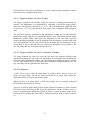
1 Introduction
This report describes the RFID technology in general and the NFC technology in
detail. It also presents the project research, construction, testing and development of
various components, circuits, constructions and software.
The report starts with a description of the RFID technology and the applications based
on the technology. It continues by describing the basic theories that the technology is
based upon. The NFC standard is then described in detail, followed by the test
standard specified for NFC. Part of this project is focused on developing a test
assembly for NFC circuits. The construction of these components and NFC modules
used in the testing are described. Finally, the various tests and the corresponding
results are presented followed by the description of the C programs developed to
control the reader and the communication in test programs and applications.
Three appendixes are enclosed: two manuals that describe how to use the test
assembly and the Demo application programs and one appendix, containing the
complete source code developed throughout the project.
1.1 Introduction to RFID
A communication system using RFID technology consists of a reader/interrogator
device and one or several transponders/tags. The tags always function as sleeping
markers regardless of the type of RFID system or application. The reader initialises
the communication by sending a signal, which is replied to in different ways by the
tags. Really simple tags like the ones used in some anti theft systems in stores do not
contain any real electronics. They consist of a diode-connected antenna, which
reflects harmonics of the transmitted reader signal frequency. In these systems the
reader transmits continuously and listens for harmonics at the same time. When it
detects a harmonic of the signal it sets of the alarm. Other, still very simple tags
receive the reader signal and then replies with a data signal containing its
identification number or other data stored in the tag. The tags mentioned above are
called read tags since they contain information that can be read only, regardless if the
information is a block of data, an identification number or simply a reflected signal
telling the reader that a tag is within reading range. More advanced tags can also be
written to by the reader. These tags are referred to as read/write tags. Examples of
simple read/write tags are the ones used in the anti theft system at libraries which can
be activated/deactivated when the book has been registered by the librarian for
lending.
Some read/write tags that need to process large amounts of data contain a
microprocessor. A disadvantage is that such a tag is quite energy consuming.
Most RFID technology use induction. When a current flows through a coil, a
magnetic field is generated around it. If another conductor or even better, another coil
is placed within this magnetic field a current is induced in it.This is used in the RFID
system. The reader antenna works as a coil providing a magnetic field, which induces
a current in the antenna coil in the tag.
1
This is where RFID differs from classic radio transceivers. Most RFID tags are
passive since they have no power supply of their own. Instead, they use the induced
current from the field generated by the reader to process the information and send a
reply. The signal can be represented in various ways.
The different distances the reader and the tags can communicate on are divided into
three areas. The reason for this is that there are distinct differences in what amounts of
energy that can be extracted from the field generated by the reader depending on the
distance to the tag [1].
1.1.1 Close coupling systems
RFID systems communicating on very short range are commonly known as close
couple systems. The range where communication is considered to be close coupled is
between 0 and 1 cm. This means that the tag has to be placed either in the reader or
more or less pressed against the reader device. The benefit from these short distances
is that a rather large amount of energy can be extracted from the magnetic field by the
tag. More energy is available for signal processing in the tag at this distance without
the need for a power supply in the tag. Close coupling is also preferred for systems
with high security requirements.
1.1.2 Remote coupling systems
Remote coupling systems operate typically in the range up to 1 m. This is the most
commonly used area for RFID systems with passive tags.
1.1.3 Long range systems
The distances in long range RFID systems are between 1 m and 10 m although
systems with significantly greater distances exist. Long range systems use the higher
frequencies specified for RFID. These systems are typically used for keeping track of
goods or marking products ready for distribution. Tags operating in long range
systems are either very simple low power consuming read only tags or active tags
containing an internal power source, e.g., a battery.
1.1.4 Frequency bands and regulations
RFID systems are classified as radio systems since they radiate electromagnetic
waves. The radio spectrum is strictly regulated with great difference between different
continents and even countries. Some frequency bands are license free and therefore
more attractive for RFID technologies. Further, a manufacturer of a system wants the
products to function at as many locations at possible. Some license free frequency
bands in Europe are not license free in North America and vice versa. However, some
bands are more common to be license free than others. The most important frequency
bands for RFID systems are 0 – 135 kHz, ISM frequencies around 6.78 MHz, 13.56
MHz (NFC), 27.125 MHz, 40.68 MHz, 433.92 MHz, 869.0 MHz, 915 MHz (not in
Europe), 2.45 GHz, 5.8 GHz and 24.125 GHz [1].
2
The frequency range below 135 kHz is not reserved as an ISM band. Electromagnetic
waves transmitted on these frequencies have physical characteristics, allowing them
to travel very far without severe propagation loss. Therefore, many radio services use
this frequency spectrum. One example is the German atomic clock signal transmitted
at 77.5 kHz from Mainflingen. This band is therefore more strictly regulated than the
ISM bands to avoid interference. Common RFID devices using 135 kHz are anti theft
transponders for cars, transponders for marking cattle and devices used for logistics,
marking goods or transportation vehicles. An advantage of the low frequency systems
is that they perform better in the vicinity of metal than higher frequency systems.
Frequencies around 6.78 MHz, as well as 135 kHz are the lowest frequencies used for
RFID. The 6.78 MHz band is among other services used for broadcasting,
aeronautical radio services and by press agencies.
The most common frequency for RFID systems is 13.56 MHz. This area is an ISM
band in most countries. Since close coupling and remote coupling systems dominate
the usage of the band, applications like readers, cell phones and sensor equipment that
collect data stored in tags are very common. An advantage of using 13.56 MHz is that
the transponders are very cheap and easy to manufacture
An ISM band is located between 26.957 MHz and 27.283 MHz. In this frequency
band, the systems are still remote or close coupled. The frequency is well suited for
remote coupled systems with a long range (about 1 m). Common applications are
access systems, different systems for tagging of goods during distribution or
production.
Another ISM band is located between 433.05 MHz and 434.79 MHz. The frequency
has very good propagation characteristics and is therefore popular. RFID systems in
this band are long range backscattered systems.
The frequency band between 868 MHz and 870 MHz is available for short range radio
devices like RFID within most of Europe since 1997. Backscatter modulated systems
are used for this frequency. The advantage of this frequency is that the read range of
the systems is better. At the same time, the frequency is still not so high that it makes
circuit implementation more complex and expensive. Typical applications are used
for marking goods and inventory.
The frequency bands 888 - 889 MHz and 902 - 928 MHz are available for backscatter
systems in the USA and Australia. Nearby frequencies are commonly used for
cordless phones. The applications using these frequency bands are the same as the
ones using the band between 868 MHz and 870 MHz in Europe.
The ISM band 2.4 – 2.4836 GHz is used more and more for RFID devices. The
wavelength is practical for building small antennas with high efficiency for long
ranges (up to around 15 m). The transponders working at such distances are active,
normally containing a battery even if laboratory experiments have succeeded for
passive circuits at ranges up to 12 m [2].
3
The ISM band between 5.725 GHz and 5.875 GHz is used for backscatter modulated
RFID systems. The advantage with the high frequency is that short wavelength equals
short antennas.
The highest frequency band for RFID is the ISM band between 24.0 GHz and 24.25
GHz. This band is specified to be used in RFID devices, even if no RFID devices
operating in the band are to be found today.
4
2 Applications of RFID and NFC
The possible applications of RFID and NFC technology are immense. As usual,
success has many fathers but failure is an orphan, thus the history of things tends to
differ between sources. Emerging from the development of radar, the transponder
technology use the same basic phenomena but adding the possibility to send data by
modulating the response signal. Starting as a World War II invention to identify friend
or foe, the technology has made its way into the civil sector. The first passive
equipment using induced energy and load modulation was probably the passive covert
listening device called The Thing, invented as an espionage tool for the Soviet
government by Léon Theremin in 1945. Transponder technology has been publicly
available since the 1960s implementing electronic article surveillance (EAS) using 1bit tags. It was not until the 1980s, with the success of electronic road toll collection,
that the technology found the widespread use discussed today.
RFID can be used for any kind of identification using data, usually a serial number
stored in the chip. The serial number can differ in bit length, but is always the basis of
the operation of the system whatever application it may serve. The number is linked
to a database containing information about the subject or item tagged. This
information is used to make a decision about, e.g., access or needed maintenance.
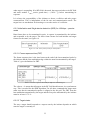
2.1 Identification
Close coupled and remote coupled systems are mostly used for identification. Close
coupled systems rely on the ISO 10536 standard. Within the remote coupled systems
there are two sub-standards defined, proximity cards (ISO 14443) and vicinity cards
(ISO 15693). Vicinity cards are built for low power and low speed. The bit rate is
usually 26 kbps and the interrogation field strength Hmin = 0.15 A/m. Due to the low
power transfer only memory cards are available as vicinity cards. An example of
vicinity cards is the I-CODE system [3], which was built to push the price per tag as
low as possible to be able to compete with bar code systems. The system handles read
and write operation at distances up to one meter and is capable of anticollision control
using timeslots. The tags have a 512 bit memory, can be rewritten 100,000 times and
has an expected lifetime of ten years.
Proximity cards are built for high power and high speed. The bit rate is ranging from
106 – 848 kbps and the interrogation field strength Hmin = 1.5 A/m. The possibility for
high power transfer facilitates cards with microprocessors and memory, but limits the
operational range to 0.1 meters. An example of a proximity cards is the Philips
MIFARE® system [4], offering different memory sizes and processing capabilities.
The memory is segmented to support a high number of different applications.
In addition to the serial number, the memory can contain encryption keys or other
data used for secure authentication The advantage of proximity cards for
identification is that the object to be identified has to place the card close to the
reader, thus minimising the risk of eavesdropping. However, the card does not have to
be inserted into the reader which makes the authentication process much faster. The
identification process is the same whether a person, animal or item is to be identified.
5
2.2 Ticketing
Numerous systems for automatic fare collection have been implemented worldwide.
High efficiency and low cost are the main reasons. Usually a transponder card is
issued to the person paying, e.g., a monthly fee. RFID systems have the advantage
over ordinary ticket systems like paper tickets or magnetic cards that they are less
sensitive to water, wear and tear and mechanic or magnetic stress. The validation
procedure is significantly faster since the card does not have to be inserted into a
machine but simply waved in front of it. Data containing the remaining value can be
stored in the chip instead of a central database, thus eliminating the need for a
constant communication link between the readers and the billing system. This data
can be encrypted for integrity and safety.
If RFID readers are placed both at entrances and exits the system can automatically
calculate and charge the correct amount for the journey. In addition to the billing,
real-time travelling measurements and statistics can be collected. Tickets can be
purchased at a regular point of sale (POS) and the process can be fully automated.
Even though most public transport companies use the same RFID technology – the
MIFARE® system is very popular in public transport – the passes are only valid in
the network of a single transport company. The use of RFID or NFC capable mobile
phones in addition to unification of different transport network passes would simplify
public transport for everyone. It would also be possible to use this system to collect
customer loyalty bonuses like frequent flyer miles etc. and for electronic booking and
check-in.
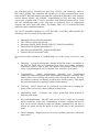
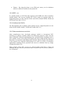
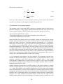
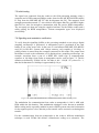
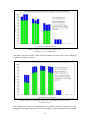
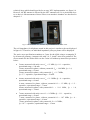
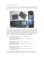
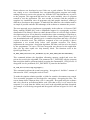
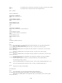
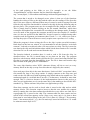
Nokia tested the NFC capable mobile phone Nokia 3220 together with the regional
public transport authority RMV (Rhein-Main-Verkehrsverbund) in Hanau, Germany,
in 2005 [5]. The contactless payment alternative is now deployed and has spread to
several shops in the city, see figure 2.1 and 2.2.
2.3 Payment
A payment can be handled in the same manner as for ticketing. There are both online
and offline systems. In an online system the serial number stored in the chip is linked
to a database containing the value or the credit limit of the user. In an offline system
the chip is pre-filled and the remaining value is stored in the memory of the chip. The
chip memory may contain a smart card emulator and smart card applications to enable
easy upgrades of older systems. The greatest consumer benefit would be if the chip
was integrated into, e.g., a mobile phone rather than a credit card, and the POS is
linked to a debit system. Upon a transaction larger than a preset threshold, the user
would be asked to agree or enter a personal identification number (PIN) or password
via the user interface of the mobile phone. Thus large transactions are secure while
small transactions are kept swift and simple. With a well implemented and marketed
standard this could be the new means for both small and large payments.
6
Figure 2.1: Bus ticket electronic payment with the NFC capable Nokia 3220
(reproduced with permission of Rhein-Main-Verkehrsverbund).
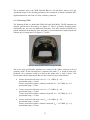
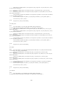
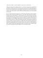
Figure 2.2: The transaction is quick and easy (reproduced with
permission of Rhein-Main-Verkehrsverbund).
MasterCard introduced its contactless payment solution PayPass in 2002. It is based
on the ISO 14443 standard and enables quick and easy payments by tapping the credit
card on the POS terminal reader. The standard ISO ID-1 credit card format is the most
common size used, but smaller tags or keyfobs and watches are available. The card is
limited to 106 kbps, but the terminals may optionally also support 212 kbps and 424
kbps. The terminals are programmed to allow only one card in the field. This
restriction ensures that the right person and card is charged with the purchase. The
communication is encrypted using standard PKI (Public Key Infrastructure)
technology. The limit for unsigned transactions varies by merchant category, but is
7
generally below USD 25. The customer can also retain possession of the card during
the transaction, which makes it feel safer.
The PayPass implementation of RFID was put through a large-scale field test in
Orlando, Florida, in 2003. More than 16,000 cardholders and over 60 retailers
participated in this trial. MasterCard in cooperation with Nokia has also tested the
PayPass technology incorporated into the Nokia 3220 mobile phone in Dallas, Texas.
Further trials have been made in cooperation with Motorola. In January 2006, 7
million PayPass cards had been issued and 30,000 merchant locations accepted
PayPass payments [6].
Visa introduced its Contactless solution in 2004. It is based on the same ISO 14443
standard and has been field tested in mobile phones in cooperation with Philips and
Nokia. In December 2005, more than 4 million Visa Contactless cards had been
issued worldwide, and more than 20,000 US merchants had implemented it [7].
2.4 Automation and logistics
RFID is playing a huge role in the area of business and manufacturing automation.
Processes can be made more efficient when the inventory or process control is
wireless and does not require an optical or manual scanning of, e.g., part numbers.
Batch sizes can be small when the ordered functions of individual items can be stored
in the chip of the item.
2.5 NFC applications in cellular phones, computers and personal area
networks.
2.5.1 Currently existing applications
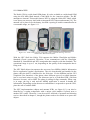
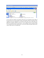
Only a few NFC compatible cellular phones are released as this report is written.
More models are released in Asia compared to Europe and USA. The Nokia 3220 is
one NFC enabled model that is available in Europe. It is equipped with an NFC
reader/writer capable of reading and writing the Mifare light standard cards. The
applications for the Nokia NFC phones marketed on their website are the possibility
to read/write web links, phone numbers and SMS to tags which then can be placed
where it is most likely to need the information. For example, a tag with the phone
number to a towing company can be written and placed on the inside of the car
windshield in case the car breaks down. Two NFC phones could also connect to each
other, enabling exchange of phone numbers, pictures, or ring tones.
2.5.2 Application visions, using NFC to control other connections.
A widely spread vision is to use NFC to connect Bluetooth devices to one another by
putting them together and thereby making the indication that they should be
connected. NFC handles the transfer of serial numbers and the initialisation signalling
[8].
8
A more recent trend is to develop cellular phones with WLAN capabilities. The
amount of people that are using WLAN technology in their homes to be able to work
connected to the Internet anywhere in the house with the laptop, or to simply connect
several computers to one Internet connection is increasing. At the same time, the use
of voice over IP (VoIP) is increasing since the phone can be used from anywhere in
the world without changing the number. VoIP is also cheaper since all communication
to other IP phones is free. The disadvantage with VoIP is that it requires a small and
preferably constant delay to be able to work. If the load on the network carrying the
traffic is too high and congestion occurs, VoIP technology is useless. With WLAN
circuits in cell phones, the phone can automatically sense when it is “home” and
switch to the cheap VoIP technology via the WLAN technology instead of using the
common GSM or UMTS interface. The advantages of NFC can be used to simplify
these transitions by simply letting the user press the phone to a reader when arriving
home, switching all outgoing calls from the cell phone to use the VoIP technology
and forwarding all incoming calls to the cell phone.
2.6 Mobile phones
2.6.1 Nokia
Nokia has two RFID/NFC compatible phone models. Both variants enable RFID
technology by the use of Xpress-on phone shells. The 5140 (and 5140i) models
support MIFARE® UltraLight tags conforming to the ISO 14443 standard [9]. The
tags have a 512-bit EEPROM read/write memory and can be operated at a distance up
to 3 cm. Anticollision is supported to handle communication if many tags are in the
range of the reader.
The 3220 model support a wider range of tags [10]. In addition to MIFARE®
UltraLight, it also handles MIFARE® Standard 1k, Standard 4k tags and forthcoming
NFC tags complying with the ECMA standards.
2.6.2 NTT DoCoMo - Osaifu-Keitai
Osaifu-Keitai is Japanese for mobile phone wallet, and relates to contactless IC card
equipped mobile phones, as well as the new and useful services enabled by the
technology. The connectivity is provided by Japanese telco (telephone company) NTT
DoCoMo and its service partners [11]. Credit, prepaid and membership cards can be
replaced by programming the IC memory with the customer details. Users can
purchase transportation and event tickets and use their phone for admission. A small
prepaid amount is available for quick purchases. Products and food can be purchased
in a tap-and-go manner. Entry details for the office and personal apartment can be
entered and used as a contactless key. ID information and personal encryption keys
may be stored to be used for identification and electronic signature. The telco acts as a
credit issuer in certain services that allows the customer to spend or withdraw money
to be later paid on the monthly telephone bill. In the same way as MasterCard Paypass
and Visa Contactless a PIN code has to be entered if the amount exceeds a
predetermined amount. Discount prices and bonuses are awarded to customers who
9
pay with their phones. Osaifu-Keitai uses Sony’s FeliCa card technology, which is
ISO 18092 (ECMA-340) compliant and capable of 212 kbps communication speed.
Sony and NTT DoCoMo began trials with this equipment in December 2005 using the
mova® Phones N504iC and SO504iC, manufactured by NEC and Sony Ericsson
respectively, together with 27 service providers from different business areas. Users
can save information data on the chip such as restaurant flyers or promotional
coupons and share them with others. In January 2006 over 10 million DoCoMo
subscribers had compatible handsets.
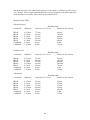
The list of compatible handsets for NTT DoCoMo, as of May 2006 includes the
following, with reservation for incompleteness.
•
•
•
•
•
•
Mitsubishi Electric D902iS and D902i
NEC N902iS, N902i and N901iS
Panasonic P902iS, P902i, P901iS, P901iTV, P506iCII and P506iC
Sharp SH902iS, SH902i and SH901iS
Sony Ericsson SO902iWP+, SO902i and SO506iC
Fujitsu F902iS, F902i and F702iD
Users can use their contactless IC enabled phone in a wide variety of services, such
as:
•
Shopping - A prepaid rechargeable amount called Edy money is available on
the chip for quick and easy payments from shops and vending machines,
without the need to enter a PIN. The balance and purchase history can be
easily viewed through the GUI (Graphical User Interface) of the phone.
•
Transportation - Public transportation companies have implemented
contactless readers throughout their infrastructure. Passengers can swipe their
mobile phone when entering and possibly when leaving the station. This way
the transport company can deduct or bill the best for the journey. This makes
the ticket infrastructure completely cashless and ticketless.
•
Ticketing - Movie tickets can be purchased and collected by swiping the
phone on the self-service counter without waiting in line.
•
Membership cards - Customers can collect points and claim bonuses at
different retail stores.
•
Keys and identification - The NFC chip can be used as a door key by storing
digital certificates in the chip. Combinations of master, ordinary and service
keys can be issued. Instead of using an ordinary apartment key, the door is
opened by simple waving the phone in front of the door or the information
panel.
•
Online shopping - Prepaid services as well as credited payments is offered in
many stores.
10
•
Finance - By using the phone as an ATM card, money can be withdrawn
which is credited or deducted on the phone bill.
2.6.3 KDDI – au
In a similar manner as NTT DoCoMo, Japanese telco KDDI also offers contactless
enabled phones and services branded EZ FeliCa, under its program name au.
Supported phones are Sony Ericsson W41S and W32S, Hitachi W42H, W41H and
W32H and Casio W41 CA [12].
2.6.4 Vodafone live! FeliCa
The third Japanese telco Vodafone offers similar services. Supported phones are the
Sharp 905SH, 904SH, 804SH, 703SHf and Toshiba 904T [13].
2.6.5 Other manufacturers and trials
Other manufacturers have developed prototype models or incorporated NFC
technology in publicly available models for field-testing purposes. Apart from the
above mentioned, Motorola and Samsung have performed trials. Samsung tested a
NFC-enabled version of the SGH-X700 model at the 2006 3GSM World Congress in
Barcelona. In cooperation with Philips and Telefonica Móviles España, 200 attendees
of the congress were supplied with the phone to be used in a variety of contactless
applications, including secure payments and access to exhibition areas by simply
swiping their phone [14].
Other countries where NFC services are offered include South Korea, China and
Thailand, but they will not be discussed more in detail as the services are similar or
less widespread.
11
3 Electromagnetism and radio circuits
RFID systems use electromagnetism to communicate. In this section a brief review of
the theory of electromagnetic waves is given.
3.1 Magnetic flux density
The basic law of static magnetic fields is the one of Biot and Savart. It is used to
calculate the magnetic field produced at a point in space by a small current element.
Using this law, and applying superposition, magnetic fields from different current
distributions can be calculated. The magnetic flux density (magnetic field) is given by
the Biot-Savart law:
dB =
μ 0 I ⋅ ds × rˆ
4π
r2
(3.1)
where I is the steady current carried in the small length element ds of the conductor
and r̂ is the unity vector directed towards the examined point. The distance from the
conductor is r and μ0 = 4π⋅10-7 Vs/Am is the permeability of free space. The total
magnetic flux density can be evaluated by integrating equation 3.1 according to:
B=
μ 0 I ds × rˆ
4π ∫ r 2
(3.2)
Note that the integrand is a vector quantity [15].
3.2 Magnetic field strength
Magnetic flux Φ is the sum of all flux passing through a surface. It is the surface
integral of the magnetic flux density B over the surface A. The connection between
magnetic field strength and flux density is given by the relation:
B = μ ⋅ H = μ0 ⋅ μr ⋅ H
(3.3)
where μ0 = 4π⋅10-7 Vs/Am and μr is the relative permeability which is dependant on
the magnetic properties of the material [16].
Current flowing in a conductor generates a magnetic field around it. The magnitude of
the field is described by the magnetic field strength H. The field strength H along a
straight conductor is given by:
H=
I
2 ⋅π ⋅ d
where I is the current in the conductor and d is the distance from it [16].
12
(3.4)
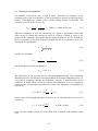
In many RFID systems cylindrical or rectangular coils are used as antennas. The
magnetic field strength along the x-axis of a cylindrical coil is given by:
H=
I ⋅ N ⋅r2
(
2r +x
2
(3.5)
)
3
2 2
where I is the current flowing through the coil, N is the number of windings, r is the
radius of the coil and x is the distance from the coil along the x-axis. In this equation
x is less than λ/2π since that is the distance where the far field begins. It is assumed
that the coil is densely wired, i.e. the distance between the wires in the coil d << r [1].
Far away from the loop, i.e. when x >> r but still within the near field limit (the near
field limit for 13.56 MHz as given above is 3.52 m), the term r2 in the denominator
can be neglected. Thus the field strength is obtained as:
I ⋅ N ⋅r2
H=
2x 3
(3.6)
where it can be seen that that the field strength is decaying with the distance to the
power of three (60 dB per decade, which is 60 dB per tenfold increase in frequency)
in the near field as discussed more below.
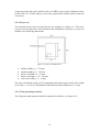
The magnetic field strength for a rectangular wire loop with side lengths a and b is
given by:
⎛
⎜
⎜
N ⋅ I ⋅a⋅b
1
1
H=
+
⎜
2
2
2
2
⎛b⎞
2
2
⎜⎛a⎞
⎛b⎞
⎛a⎞
⎜ ⎟ +x
4 ⋅π ⋅ ⎜ ⎟ + ⎜ ⎟ + x2 ⎜ ⎜ ⎟ + x
⎝ 2⎠
⎝⎝2⎠
⎝2⎠
⎝2⎠
⎞
⎟
⎟
⎟
⎟
⎟
⎠
(3.7)
where x is the distance along the x-axis [1].
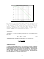
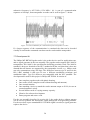
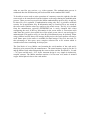
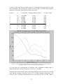
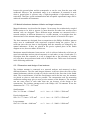
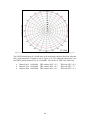
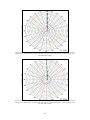
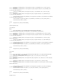
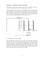
The magnetic field strength H is fairly constant until the distance from the centre of
the coil x equals the radius r. At that distance the field strength starts to decline at a
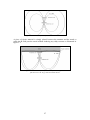
rate of 60 dB per decade. It can be seen in figure 3.1 that a small wire coil generates a
stronger magnetic field in the centre of the coil than one with a larger radius at the
same current. However, the bigger coil has a stronger field at large distances.
13
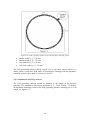
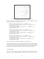
Figure 3.1: Magnetic field strength H as a function of distance x, for circular coils
r = 1 cm (solid green), r = 7.5 cm (dashed red), r = 55 cm (dotted blue).
If the distance x is kept constant and the radius r of the coil is varied it can be seen
that the magnetic field strength has a maximum when x ≈ r/√2, as described in section
5. With knowledge about the minimum field strength required for transponder
operation, the dimensions of the reader antenna can be determined. An overdimensioned reader antenna may not generate a magnetic field strong enough to
operate the RFID chip even if it is placed close to the reader, i.e. x = 0.
3.3 Inductance
The total flux Ψ is the sum of the flux Φ generated by every of the N number of coil
loops, thus:
Ψ=N⋅Φ=N⋅μ⋅H⋅A
(3.8)
The inductance L of a coil is the ratio of the total flux Ψ to the current I [1]:
L=
Ψ N ⋅μ⋅H ⋅A
=
I
I
(3.9)
3.4 Mutual inductance
A second coil located in the vicinity of a first coil will be affected by the magnetic
flux generated by it. A portion of the flux will flow through the second coil. This flux
is called the coupling flux and connects the two coils inductively. The quality of the
inductive coupling depends on the geometry of the two coils, their position relative to
each other and the permeability of the medium between them. The mutual flux that
passes through both coils is called the coupling flux Ψ21.
14
The mutual inductance M21 is defined as the ratio of the coupling flux Ψ21, which
passes through the second coil, to the current I1 in the first coil [1]:
M 21 = N 2 ⋅
B
Ψ21
= N 2 ∫ 2 dA2
I1
I
A2 1
(3.10)
The same relationship applies the other way around. A current I2 in the second coil
will generate a magnetic field that will induce a current in the first coil through the
coupling flux Ψ12. The mutual inductance is the same either way:
M = M 12 = M 21
(3.11)
Inductive coupling via mutual induction is the principle upon which the vast majority
of passive RFID transponder tags and systems are based. They rely on this
phenomenon for both power and data transfer. It is important that the reader antenna
is sufficiently large to supply the transponder antenna with a large enough field to fill
its area.
3.5 Coupling coefficient
To be able to measure the efficiency of the inductive coupling between two conductor
coils the coupling coefficient k is introduced:
k=
M
L1 ⋅ L2
(3.12)
The coupling coefficient varies between total coupling when k = 1 and full decoupling
when k = 0. In the case of total coupling, both coils are subject to the same magnetic
flux. An example of total coupling is a ferrite core transformer. Full decoupling might
occur when the distance between two coils becomes too large or when they are
perpendicular to each other. Inductively coupled RFID systems may operate with
coupling coefficients as low as a few percent.
3.6 Faraday’s law
Faraday’s law governs the connection between magnetic flux Φ and electric field
strength E. Any change in magnetic flux will generate an electric field. The properties
of the electric field generated depend on the materials surrounding the flux. In RFID
technology some different situations are of interest.
If alternating magnetic flux is flowing through an open conductor loop a voltage is
induced over the gap of the loop. A change in flux flowing through a metal surface
generates currents in the metal. According to Lenz’s law, these so-called eddy
currents will counteract the magnetic flux and therefore hinder the performance of
RFID systems. If a RFID tag needs to be placed on a metallic surface, e.g., a gas
bottle, a layer of highly permeable material may be used between the tag and the
15
metal surface to prevent the formation of eddy currents, thus enabling operation of the
system. However, the layer of magnetic material may change the inductance of the
transponder antenna coil and thus altering the resonance frequency.
The induced voltage in the transponder antenna coil is used as power supply for data
transmission. The inductive coupling can be visualized as a transformer. However,
when the induced voltage over the coil is connected to the transponder load the
current flowing through the circuit will generate a second, smaller magnetic flux
counteracting the flux from the reader.
Most RFID systems use sinusoidal currents and the different parts of the total flux
responsible for the induced voltage can be summed up as:
u tag = j ⋅ ω ⋅ (M ⋅ ireader − Ltag itag ) − itag Rtag
(3.15)
where ω = 2 ⋅ π ⋅f is the angular frequency [17].
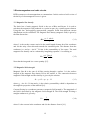
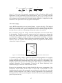
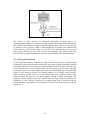
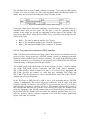
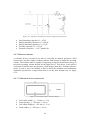
3.7 Resonance circuits
Passive transponder chips use the induced voltage utag to power its electronics.
However, with an insufficient coupling coefficient, the voltage might be to low. In
order to increase the voltage a capacitance can be put in parallel with the antenna coil
to form a resonance circuit, see figure 3.2.
Figure 3.2: Electric equivalent schematic for a transponder.
If the resonance frequency corresponds to the RFID system frequency the resonance
circuit will give a voltage step-up in the order of its Q factor (Quality factor). The Q
factor is a measure of the quality of a resonance circuit and is defined as 2π times the
ratio of the maximum energy stored in the system at any instant to the energy
dissipated per cycle [18]. In practice, inductors tend to be lossier than capacitors. No
extra parallel capacitance is needed in the high frequency band where 13.56 MHz
systems can be found since the input capacitance of the microchip together with the
parasitic impedance of the coil is sufficient.
For every combination of coil resistance and load resistance there is a value of
inductance for the coil that maximizes the Q value according to:
16
1
Q=
1
Rload
Lcoil
C tot
⋅
+ Rcoil ⋅
C tot
Lcoil
=
1
Rcoil
ω ⋅ Lcoil
+
Rload
ω ⋅ Lcoil
(3.16)
where Ctot is the sum of the parasitic capacitance of the coil and the added parallel
capacitance (or chip capacitance in the high frequency case) [1]. It can be seen that
with a low coil resistance and a high load resistance a high Q value is achieved. Low
coil resistances can be attained by using high quality inductors. A high load or chip
resistance is the equivalent of low chip power consumption.
3.8 Power supply
Active RFID transponders use an internal battery to power the chip. The induced
voltage utag is merely used as a wake up indicator to put the transponder in signalling
mode. As mentioned above, passive transponders use the induced voltage to power
the chip. However, this is an alternating current that needs to be rectified.
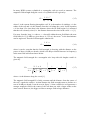
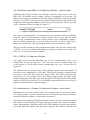
Due to resonance step-up the voltage across the transponder circuit can reach values
by the hundred. Therefore, protective measures have to be taken not to damage the
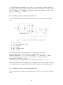
circuit. The most common choice is to place a regulator in parallel to the load. This
so-called shunt regulator, usually consists of a Zener diode controlling a transistor,
refer to figure 3.3. When the voltage reaches the maximum operating voltage, usually
around 3 volts, the regulator starts draining current in proportion to the increased
voltage thus keeping it constant.
Figure 3.3: Semiconducting shunt regulator using a Zener diode and an NPN transistor.
To reach the operating voltage a sufficient magnetic field strength has to be supplied
to the transponder antenna coil. This minimum level is called the interrogation field
strength and limits the operational range of the RFID system. It is dependent on the
frequency used by the system. The interrogation field strength is reached when the
resonance frequency of the transponder is tuned to the system frequency, since
maximum step-up is achieved in the resonance circuit.
However, the operational range is further limited by the power consumption of the
transponder and the ability for the reader to detect what is transmitted. It is also
important that the reader and transponder are positioned to each other in a way that
enables efficient induction. If the reader is placed perpendicular to the transponder,
the magnetic flux will not pass through its antenna coil, thus not generating enough
power to operate the tag.
17
4 Data Transfer
The way data is transferred in RFID systems varies depending on application and type
of coupling. Close coupled and remote coupled systems have a magnetic couple to
one another through the mutual inductance M that allows rather unusual methods of
communication to be used. Long range systems on the other hand communicate on
distances too great to have enough mutual inductance between reader and tags for
these methods to be used. Other radio technologies are used instead for long range
systems.
4.1 Modulation
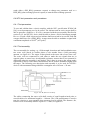
4.1.1 Load modulation
This is a modulation technique used only by close and remote coupled systems. The
technique makes use of the short distance between the reader and the transponder coil.
When the reader antenna coil generates a signal around its frequency fr the nearby
transponder is magnetically connected to the reader through its antenna coil. A current
is induced in the transponder coil. According to Lenz’s law the induced current tries
to counteract the field that induced it [19]. This effect is transferred to the reader
transmitter circuit via the mutual inductance M and can be measured as a voltage drop
over the antenna coil impedance. When the transponder circuit is loaded the voltage
drop is increased. This allows communication from the transponder back to the reader
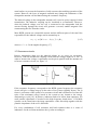
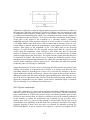
by simply varying the load of the transponder circuit, see figure 4.1. Modulation of
the load can be accomplished both by a variable modulation resistance connected in
parallel with the load as well as with a variable modulation capacitor connected in
parallel with the load resistance. The two methods are referred to as ohmic load
modulation and capacitive load modulation. Ohmic load modulation in the
transponder generates amplitude modulation at the reader antenna branch while
capacitive load modulation in the transponder generates a combination of amplitude
and phase modulation at the receiver branch. The difference in phase at the reader
antenna when capacitive load modulation is applied arises from the transformed
transponder impedance. The voltage drop at the reader antenna arises when the
transponders impedance is transformed via the magnetic couple to the reader antenna
branch. A completely resistive impedance in the transponder will move only along the
real axis while capacitive transponder impedance makes a turn in the Smith chart
causing a change in value of both the real and the imaginary axis [1].
A widely used approach for systems in the frequency bands 6.78 MHz, 13.56 MHz
and 27.125 MHz is to first modulate a subcarrier with frequency fs, and then use the
subcarrier to modulate the main carrier with frequency fc. This results in a modulation
product, generating two sidebands symmetrically at the frequencies f c ± f s . The
modulation techniques for subcarrier modulation are amplitude shift keying (ASK),
frequency shift keying (FSK) and phase shift keying (PSK).
18
Figure 4.1: Magnetically coupled reader and transponder circuit,
showing the transformed transponder impedance “Z_t.
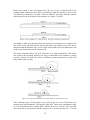
4.1.2 Backscatter modulation
Backscatter modulation is used in systems communicating over long range, typically
1–10 meters. At this distance, the magnetic coupling between the reader coil and the
transponder coil is far too weak to use load modulation as in remote coupled systems.
Instead a modulation method working in a similar way as a radar system is used [20].
The technique takes advantage of the fact that a receiver antenna under some
conditions can reflect parts of an incoming wave. In most radio systems the designer
would take actions to avoid this to occur since it makes the receiver a transmitter or
repeater of the received signal. An antenna with an inner impedance Ra should be
connected to a receiver circuit with entry impedance equal to Ra for maximal effect
absorption. This is basic knowledge within all circuit design. If this is the case, all
effect received by the antenna will be absorbed by the circuit. If the entry impedance
instead is totally mismatched by short-circuiting the receiver entry or leaving the entry
completely open, the antenna will reflect the received wave. The phase of the
reflected wave is changed compared to the phase of the wave originally sent by the
reader (sent wave(φ), reflected wave(φ ± π)). The phase shift in the far weaker
reflected signal makes it possible to easily separate it from the transmitted one at the
reader transceiver.
The implementation of backscatter modulation at the transponder is usually
accomplished by simply connecting a field effect transistor (FET) over the antenna.
The gate of the FET is then modulated with the signal to be transmitted, making the
FET to short circuit / open the antenna dependent on the signal to the gate [1]. To
detect the signal from the transponder, the reader only needs to subtract the carrier
frequency from the total signal, using the same local oscillator “LO”, which was used
to generate the original signal. The resulting signal will be the fragments reflected by
19
the transponder, which is illustrated in figure 4.2. The fragments correspond to
amplitude shifty key modulation.
Figure 4.2: Communication using backscatter modulation.
4.2 Modulation with subcarrier
When the raw data signal is used to directly modulate either the load or the FET
depending on couple mode, the result in the reader is Amplitude modulation
(Capacitive load modulation results in a phase shift as well but in most cases the
amplitude is the information carrier). The information signal to be sent in the
transponder is however sometimes first modulated with a subcarrier. The modulated
subcarrier is then used to amplitude modulate the main carrier. When a subcarrier
with frequency f s is used, the data is located in the sidebands at f c ± f s . When using
this approach the subcarrier modulation techniques is not necessarily ASK. The
techniques used in existing systems today for subcarrier modulation are ASK,
frequency shift keying (FSK) and phase shift keying (PSK). Since all communication
in existing RFID systems today is binary (M = 2), the techniques are described under
this condition [21].
4.2.1 ASK
Amplitude shift keying (ASK) is realized simply by changing the amplitude of the
signal to transmit between two values. Modulation index is measured as:
M = (A+B)/(A–B) where A is the high amplitude and B is the low.
4.2.2 FSK
In frequency shift keying the frequency of the signal to be transmitted is simply
switched between two different frequencies representing ‘1’ or ‘0’.
20
4.2.3 PSK
Phase shift keying does not change the amplitude or frequency of the signal to
transmit. Instead, changing the phase of the carrier between 0 and π represents the
data. In some systems, it is a great benefit that the PSK signal is a signal with constant
envelope and frequency.
4.3 Transmission modes
Data transmission in RFID and NFC systems can take place as both half and full
duplex transmission. Another transmission mode belonging to the half duplex is
sequential systems (SEQ). A SEQ transponder has a charging capacitor built in
making it possible for the passive transponder to generate its own magnetic field.
When communicating in SEQ the reading cycle consists of two phases: the charging
phase and the reading phase. During the charging phase the reader can send data to
the transponder or simply send the carrier frequency signal. The reader then stops
generating the magnetic field. An “end of burst detector” in the transponder detects
this. During the following reading phase, the transponder transmits by generating a
field, using an on chip-oscillator. Using SEQ improves the signal to interference ratio
and increases the possible reading range.
21
5 Antennas
When designing antennas for RFID systems several conditions need to be met.
Antennas used for close coupled and remote coupled systems are designed after
completely different criteria than antennas used in long range systems. The two cases
are therefore investigated separately.
5.1 Antennas for close and remote couple systems
The antennas used in close and remote coupled systems are not really antennas in the
classic radio meaning. The electric component (E-field) in the Electromagnetic field is
not used for communication in these systems. Instead, the magnetic component
(B-field) is used through modulation of the load. The antennas in this type of
communication are actually coils. A magnetic field is generated by the reader,
inducing a current in the transponder antenna coil, see figure 5.1.
Figure 5.1: Reader and transponder coils in a magnetic coupled system.
The current induced in the transponder needs to be strong enough to support the
transponder circuit with power. The important parameters to consider when designing
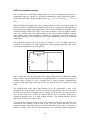
the coils for this type of system are maximum reading range and the minimum amount
of power needed in the transponder for it to be operable. The optimal reader coil
diameter can be found from the relationship [22]:
ΝΙ = K
(a 2 + r 2 ) 3 / 2
a2
where K =
2Bz
μ0
(5.1)
Deriving the expression for NI with respect to the radius:
d ( NI )
(a 2 − 2r 2 )(a 2 + r 2 )1 / 2
=K
da
a3
(5.2)
The expression is minimized for a = r 2 , where a = radius of coil and r = read
range.
22
5.1.1 Antenna coil properties
The antenna coil needs to have a high Q factor. Therefore the resistance of the
conductor wire of the coil should be as low as possible to achieve an efficient power
transfer. This applies to systems where a long reading distance is desirable. The
resistance of a wire at DC is given by:
R DC =
l
l
=
σ ⋅ S σ ⋅π ⋅ a2
where a = radius of the wire.
(5.3)
When the conductor is used for transferring AC signals a phenomena called skin
effect occurs. It causes the currents to travel in a region of depth δ close to the
surface of the conductor. This means that for higher frequencies, the DC formula for
the wire resistance is not valid. Instead, a formula for the AC resistance is used. The
expression for skin depth is:
δ=
1
(5.4)
π ⋅ f ⋅ μ ⋅σ
And the AC resistance:
R AC =
l
l
≈
σ ⋅ Aactive 2π ⋅ a ⋅ δ ⋅ σ
(5.5)
The skin depth area of the conductor is:
Aactive ≈ 2π ⋅ a ⋅ δ
(5.6)
The inductance of the coil can also be calculated mathematically. This calculation
should however be considered as an approximation of the actual inductance since it is
very hard to accurately calculate the inductance, because of parasite effects in the
conductor. It might still be useful to calculate the inductance even if it should be
measured later to assure that it has the correct value. The inductance of a straight wire
is given by:
L = 0.002 ⋅ l ⋅ (ln(
2⋅l
3
) − ) ⋅ 10 − 4
4
a
(5.7)
where l and a is the length and radius of the wire in cm. The inductance of a wire coil
if given by:
⎛ 2R ⎞
L = N 2 μ 0 R ⋅ ln⎜
⎟
⎝ d ⎠
if d/2R < 0.0001
(5.8)
where N is the number of turns, R is the radius if the coil and d is the diameter of the
wire.
23
The Q factor is defined as:
Qs =
Qp =
ωL s
Rs
Rp
ωL p
=
1
R s ωC s
= R p ωC p
5.9)
(5.10)
where Qs is the Q factor for a series resonance circuit, Qp is the Q factor for a parallel
resonance circuit and ω is the angular resonance frequency [18].
5.2 Antennas for long range systems
The antennas used in long range RFID systems are operating in the far field and are
therefore designed in a more classic antenna matter than the ones used for close and
remote coupled systems. The RFID long range transponder antenna is used for:
-Receiving the signal from the reader.
-Absorbing enough power to supply the transponder circuit with power.
-Transmitting signals back to the reader.
Apart from this, the circuits used for long range systems are often used in systems
keeping track of goods. To keep costs at a low level the circuits should be small,
cheap and being operable in sometimes shaded environments, e.g., warehouses.
Which type of antenna that is used in general for RFID applications is impossible to
say. In some services using RFID, a reader is placed at a fixed position and detects
transponders passing by. One example of such a system is the ones used at toll roads
to register payment for vehicles passing by. In this situation the transponders in the
cars will always approach the reader from the same direction. If the transponder is
placed according to instructions on the inside of the windshield the reader will know
exactly were to transmit its signal when searching for transponders. These types of
systems use a directional antenna to avoid waste of energy.
A very commonly used antenna is the loop antenna. The advantages with the loop
antenna are that its form makes it practical to place in practically any device. Loop
antennas considered small loop antennas are antennas with a total length
(circumference) smaller than or equal to about one tenth of a free space wavelength
[23]. Small loop antennas can be compared to small dipole antennas when it comes to
radiation pattern in the far field.
Another common antenna used in RFID systems is the dipole antenna. A dipole
antenna oriented along the z-axis has an equal radiation pattern in all directions in the
x,y – plane. This makes it well suited for applications were the reader does not know
where the transponder is located. When antennas are actually constructed for a RFID
transponder, the antennas are often in form of microstrip or patch antennas. The patch
antennas can be constructed either as loop antennas, dipole antennas or folded dipole
antennas. For really small mass-produced simple circuits like the tags used for
marking single products, the latest technique is to simply print the antenna on a card
24
using inductive ink. Some electric components can also be printed the same way. This
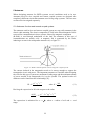
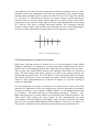
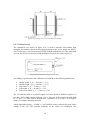
technique reduces the production costs of the tags significantly [24]. A rather strange
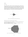
looking antenna design useful in readers for some services is the Yagi-Uda antenna
[1], see figure 5.2. The antenna is built up by a dipole acting as exciter operating at
resonance. One or several parasite, shorter dipoles are placed in front of the exciter
acting as directors. A dipole, longer than the exciter is placed behind the exciter acting
as a reflector. This gives a strongly directional antenna. The advantage with this
antenna is that it can be used to point at the directions were the wanted transponders
are located. Other transponders located sideways of the antenna are ignored.
Figure 5.2: Yagi-Uda antenna.
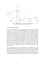
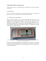
5.3 Placing antennas in metal environments
Many times, antennas need to be placed close to or even mounted on metal. Metal
introduces difficulties for antennas in systems using radio communication in the far
field as well as for antennas in inductively coupled systems working in the near field.
This is a big issue within RFID research since antennas often need to be placed on
metal. The most simple and cheap solution is to allow some spacing between the
antenna and the metal surface. For 13.56 MHz, 2-3 cm of air spacing between antenna
and metal is sufficient to assure practically no negative effects from the surrounding
metal. For NFC implementations in cell phones or laptops, 2–3 cm of air spacing is
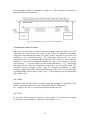
mostly not affordable.
Several phenomena occur when an antenna coil is placed close to metal. The metal
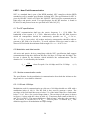
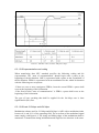
decreases the inductance of the coil causing the Q factor to drop and self-resonance
frequency to change. As an example, a Phillips Mifare 1k card changed from having
Q = 22 and fres = 18.9 MHz with only air surrounding to having Q = 13 and fres = 28.1
MHz when placed upon a metal surface and measured with a network analyser. The
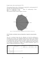
other major effect, having the worst impact on the communication in metal
environment is that the magnetic field induces eddy currents in the metal. The eddy
currents create a counteracting magnetic field according to Lenz’s law, see figure 5.3.
This creates a minimum close to the metal surface and prevents communication.
25
Figure 5.3: Eddy currents create a counteracting B-field.
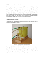
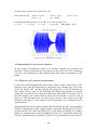
The effect of eddy currents is commonly illustrated in basic physics or
electromagnetic field theory courses by letting a magnet fall through both a metal tube
and a plastic tube. When the magnet falls through the plastic tube, it is only affected
by Newton’s law of gravity. When it falls through the metal tube, the counteracting
field created by eddy currents cause the fall time of an equal distance to be several
times longer than in the case with no metal surroundings. This implies that eddy
currents cause a significant difference and has to be included in design calculations.
5.3.1 Waveguide materials
To avoid that the magnetic field induces eddy currents which creates a counteracting
field and prevents communication when metal is present, a highly permeable material
with high resistivity can be used to guide the magnetic field away from the metal. Soft
ferrite materials have good characteristics for this purpose. Since these materials
already have been very useful within other radio areas than RFID (e.g., to reduce SAR
values in cell phones), several well suiting products are available on the market.
These products usually consist of resin layer mixed with powdered ferrite. This
solution makes the material soft and formable instead of hard and fragile. The
magnetic field is transported in the material and the high resistivity prohibits the
formation of eddy currents. Therefore, no counteracting field is produced and the
communication is not hindered. The magnetic field when no metal is present is shown
in figure 5.4.
26
Figure 5.4: Illustration of the B-field in non-metal environment.
A piece of ferrite material is simply placed between the antenna and the metal to
guide the B field past the metal without inducing any eddy currents as illustrated in
figure 5.5.
Figure 5.5: Illustration of the B field when a ferrite waveguide is
placed between the target antenna and the metal.
27
6 NFC – Near Field Communication
NFC is a standard that is part of the RFID standard. NFC complies with the RFID
standard as well as another specification, defining NFC. The specification for NFC is
given by ISO/IEC 18092 or ECMA-340. ISO/IEC 18092 specifies communication in
both active and passive mode. Test specifications for the RF interface is found in
ECMA-356 and protocol tests are specified in ECMA-362 [25].
6.1 The RF specifications
All NFC communication shall use the carrier frequency fc = 13.56 MHz. The
bandwidth of the system is fc ± 7 kHz . Max/min values for the RF field, between
which all transponders should be continuously operable are H min = 1.5 A / m ,
H max = 7.5 A / m (rms value). All readers and active transponders should be able to
generate a RF field of at least Hmin. To avoid collision all devices must be able to
detect a RF field with the minimum field strength H threshold = 0.1875 A / m .
6.2 Modulation and data transfer
All active and passive devices complying with the NFC specification shall support
communication using three different bit rates 106 kbps, 212 kbps and 424 kbps. The
bit rate is chosen by the initiator, which initialises the communication. The bit
duration “bD” is calculated by the formula:
bD =
128
where D equals 1 for 106 kbps and 2 for 212 kbps.
(D × f c )
(6.1)
6.2.1 Active communication mode
The specification for the modulation in communication from both the initiator to the
target and vice versa shall be identical.
6.2.1.1 Bit rate 106 kbps
Modulation used for communication at a bit rate of 106 kbps should use ASK with a
modulation index of 100 %. The RF field is here used to generate a pause. The
envelope of the field shall decrease to below 5 % of the initial value HInitial and remain
below 5 % of HInitial for a period longer than t2. The envelope of the pause is shown
in figure 6.1 along with the values in table 6.1. Transients shall remain within 90 %
and 110 % of HInitial. The target shall detect “End of pause” after the value exceeds 5
% and before it exceeds 60 % of HInitial. “End of pause” is defined by t4. This
definition applies to all modulation envelope timings.
28
Figure 6.1: Pause shape of 100 ASK modulated 106 kbps signal.
Table 6.1: Max/min values in 100% ASK pause shape.
6.2.1.2 Bit representation and coding
When transferring data NFC standard specifies the following coding and bit
representation. The “start of communication” should begin with a pause at the
beginning of the bit duration. ONE is represented with a pause at the second half of
the bit duration. ZERO is represented with no modulation for the whole bit duration
with the following two exceptions:
-If there are two or more contiguous ZEROs, from the second ZERO a pause shall
occur at the beginning of the bit duration.
-If the first bit after “start of communication” is ZERO, a pause shall occur at the
beginning of the bit duration.
The type of byte encoding that shall be applied for the 106 kbps case is least
significant bit (lsb) first.
6.2.1.3 Bit rate 212 kbps and 424 kbps
Modulation scheme used for 212 kbps and 424 kbps is ASK with a modulation index
between 8 % and 30 % of the operating field. The waveform of the modulated signal
must comply with figure 6.2. The rising and falling edges of the modulation shall be
monotonic. Transmission during initialisation and single device detection is the same.
29
The peak and minimum values of the modulated signal are defined by “a” and “b”,
see figure 6.2 and table 6.2.
Figure 6.2: Modulated waveform.
Table 6.2: Values in ASK signal with modulation index between 8 % and 30 %.
6.2.1.4 Bit representation and coding
When transferring data using bit rate 212 kbps or 424 kbps, the NFC standard
specifies that Manchester bit encoding should be used. Reverse polarity in the
amplitude of the Manchester symbols is permitted. Polarity shall be detected from the
SYNC (synchronous pattern). The byte encoding shall be most significant bit (msb)
first.
6.2.2 Passive communication mode
The bit rate and modulation scheme for transmission during initialisation and single
device detection from the initiator to the target in the passive mode is the same as the
one specified for the active case. All communication from the initiator, generating the
30
RF field follows the same specifications as for the communication using the same bit
rate in the active communication mode.
6.2.2.1 Target to initiator, bit rate 106 kbps
The target responds to the initiator using the inductive coupling generated by the
initiator. The modulation is accomplished by switching a load in the target using a
subcarrier with subcarrier frequency fs = fc/16. The load modulation amplitude must
be at least 30 / H1.2 (mV peak) where H is the (rms) value of magnetic field strength in
A/m.
The subcarrier shall be modulated using Manchester coding for bit representation.
Manchester coding with obverse amplitudes shall be used. That means that the binary
Manchester symbol ZERO shall have low amplitude for the first half of the bit
duration and high amplitude for the second half of the bit duration. Symbol ONE shall
have high amplitude for the first half of the bit duration and low amplitude for the
second half of the bit duration. Reverse polarity in amplitude is not permitted. The
byte encoding shall be least significant bit (lsb) first.
6.2.2.2 Target to initiator, bit rate 212 kbps and 424 kbps
The target responds the same way as in the 106 kbps case with the difference that
subcarrier modulation is not used. The modulation is accomplished by switching the
load, generating Manchester coding. The load modulation amplitude must be at least
30 / H1.2 (mV peak) where H is the (rms) value of magnetic field strength in A/m. The
byte encoding is most significant bit (msb) first.
6.3 NFC protocols
A NFC device can be either in target mode or initiator mode. Passive devices are
always in target mode. The device shall per default be in target mode unless the
application tells it to switch into initiator mode.
When a device is in target mode it shall wait silently for an externally generated
RF field from the initiator to activate.
A device in initiator mode shall perform initial collision avoidance to detect external
RF fields before activating its RF field. The application decides whether active or
passive communication should be applied. If passive, it must perform single device
detection before starting the data transfer. The protocol flow chart is shown in figure
6.3.
31
Figure 6.3: Protocol flow chart for NFC initialisation and SDD.
6.3.1 Collision avoidance
Mechanisms for collision avoidance are specified for NFC. Devices generating RF
fields do initial collision avoidance by sensing the carrier for already existing RF
fields. If an RF field stronger or equal to Hthreshold is detected, the RF field is not
switched on. If no RF field is detected within a time period of TIDT + n × TRFW , where
TIDT (initial delay time) > 4096 / fc, TRFW (RF waiting time) = 512 / fc and n is a
random generated integer between 0 ≤ n ≤ 3 , the RF field is switched on. The initiator
then waits TIRFG (initial RF guard-time) > 5 ms before starting to transmit a request.
A similar collision avoidance procedure called response RF collision avoidance is
performed in active mode communication where the target replies to an initiator
request generating its own RF field. The targets wait (768 / fc) ≤ TADT (active delay
time) ≤ (2559 / fc) + n × TRFW during which time it senses the carrier to assure that no
32
other target is responding. If no RF field is detected, the target switches on its RF field
and waits another TARFG (active guard time) > (1024 / fc) before transmitting its
response.
It is always the responsibility of the initiator to detect a collision and take proper
counteractions. This is independent of the bit rate and communication mode. The
targets have no mechanism for detecting or even take notice of a collision.
6.3.2 Initialisation and Single device detection (SDD) for 106 kbps – passive
mode
Data frames have to be transmitted in pairs. A request is transmitted by the initiator
and responded to by the target. The basic frame format for both initiator and target
frames are the same, see figure 6.4.
Figure 6.4: The basic frame format for NFC frames.
6.3.2.1 Frame response time (FRT)
The frame response time is the time between the end of the last transmitted pulse by
the initiator and the first modulation edge within the start bit transmitted by the target.
Table 6.3 gives definitions for FRT.
Table 6.3: Frame response time FRT for different command types.
The value n = 9 means that all targets in the RF field should answer in a synchronous
way. This is needed for the SDD algorithm. For all other commands the target must
make sure that its transmitted response is aligned to the bit grid. The FRT from the
last modulation transmitted by the target and the first pulse transmitted by the initiator
must be at least 1172 / fc.
6.3.2.2 Target states
The way a target should respond to a request sent by the initiator depends on which
state the target is currently in.
33
POWER OFF state.
In the power off state, the target shall not be powered by the initiator RF field since
the field is weaker than Hmin. If the target receives a field stronger than Hmin it should
enter SENSE state.
SENSE state.
The target is powered by the initiator RF field and listens for SENS_REQ (Sense
request) and ALL_REQ (wake up all request). If the target receives a valid
SENS_REQ or ALL_REQ and replies with its SENS_RES (Sense response) it should
enter RESOLUTION state. If the target receives other valid or invalid commands, it
should remain in SENSE state.
RESOLUTION state.
The bit single device detection algorithm is applied in this state. If SDD is completed
for the target and it receives a valid SEL_REQ (Select request) and responds with
SEL_RES (Select response), it should enter SELECTED state. If the target receives
other valid or invalid commands, it shall return to SENSE state.
SELECTED state.
The target shall listen depending on the coding in the SEL_RES to an ATR_REQ
command or a valid proprietary command. The target shall enter SLEEP state when a
valid SLP_REQ (Sleep request) command is received. The DSL (Deselect)
commands return the target to SLEEP state. If the target receives any other valid or
invalid commands, it shall return to SENSE state.
SLEEP state.
The target shall only respond to ALL_REQ and enter RESOLUTION* state after it
has received a valid ALL_REQ and has responded with SENS_RES. For all other
valid or invalid commands, the target shall remain in SLEEP state.
RESOLUTION* state.
This state is equal to RESOLUTION state with the exceptions that after completed
SDD signalling the target shall enter SELECTED* state instead. When the target
receives any other valid or invalid commands it shall return to SLEEP state.
SELECTED* state
This state is equal to SELECTED state with the exception that if the target receives
any other valid or invalid command than the ones specified for SELECTED state it
shall return to SLEEP state instead.
6.3.2.3 Frames
Two types of data frames are used for 106 kbps. The short frame is used during
initialisation, see figure 6.5. It contains 7 bits without parity bits, used for command
coding, transmitted lsb first.
Figure 6.5: Short frame used for command coding.
34
The standard frame is used for data exchange. It contains 7 bytes and one added parity
bit after every byte, see figure 6.6. The parity bit should make sure that the number of
ONEs in the previous byte (including the parity bit) sums up odd.
Figure 6.6: Standard frame used for data exchange.
During the single device detection signalling, a special frame is used. This frame is a
standard frame, split into two parts. The first part is used for signalling from the
initiator to the target, the second for signalling from the target to the initiator. The
split can be done after a whole byte or within a byte. Only three rules define how the
frame can be split.
•
•
•
Rule 1: The sum of data bits shall be 56 (7 bytes).
Rule 2: The minimum length of part 1 shall be 16 data bits.
Rule 3: The maximum length of part 1 shall be 55 data bits.
6.3.2.4 The single device detection (SDD) algorithm
SDD is used to avoid collisions and only transfer data between the initiator and one
target at a time. Every target has a NFCID1 number, which is a randomly generated
identifier used for SDD in passive mode at 106 kbps. The result of the SDD algorithm
is that the initiator gives its clearance to one target to enter SELECTED state and start
communicating, exchanging data with the initiator.
The obliged length of the SDD frame sent by the initiator (16 bits = 2 bytes) contains
two fields SEL_CMD “Select Command” and SEL_PAR “Select Parameter”.
SEL_CMD specifies which cascade level that is to be used in the algorithm and
SEL_PAR specifies the number of valid data bits including SEL_CMD and
SEL_PAR. From this parameter it can be calculated how many bits of the NFCID1
number that is being transmitted.
In the first loop of SDD, the SEL_PAR is set to (20) indicating that no NFCID1
number is transmitted. This forces all targets within the field to reply with their
complete NFCID CLn which is the NFCID1 for a given cascade level (CL) n. If more
than one target responds a collision will occur. The initiator registers the position of
the collision and increases the cascade level. During next loop, the initiator sends
along the fragment of the NFCID1 number that was registered before the collision. A
target which NFCID1 number does not match the fragment remains silent. For every
loop the initiator collects a further fragment of the NFCID1 number eliminating
targets, until only one remains.
35
6.3.3 Initialisation and SDD for 212 kbps and 424 kbps – passive mode
Signalling when using 212 kbps and 424 kbps is done the same way as in the 106
kbps case. The initiator sends a request, which is responded to by the target. The
frames used consist of a preamble of minimum 48 bits, all ZEROs. After the preamble
follows 16 bits SYNC where the first byte shall be 0xB2 and the second 0x4D, 8 bits
length field, indicating the numbers of bytes plus one in the payload. Finally, the CRC
(cyclic redundancy check) is added, see figure 6.7.
Figure 6.7: Basic frame for 212, 424 kbps passive communication mode.
The “Start of communication” is recognized from the preamble (48 bits all ZEROs)
while the “End of communication” is simply known to the receiver from the length
field. In this communication mode reverse polarity of the Manchester coding is
allowed. Which polarity that is used is easily seen from the SYNC field since it
always has a fixed value. The payload shall consist of an even number of bytes.
There are no FRT schemes for this communication mode. The only rule is that a when
a NFCIP-1 device has finished transmitting, the other part shall wait a period of at
least (8 * 64 / fc) before starting to transmit.
6.3.3.1 SDD for 212 kbps and 424 kbps
The single device detection algorithm used for this communication mode is far
simpler than for the 106 kbps case. Time slots are used for communicating with
several targets in a TDM (time division multiplexing) way. Up to 16 time slots are
supported.
The initiator starts by sending a POL_REQ (polling request) where the number of
time slots to use is indicated in a TSN value. The target(s) calculate a random integer
R between 0 and TSN. The target then replies with a POL_RES in the time slot
indicated by R. If a collision occurs, the initiator simply repeats the SDD. When
targets transfer their POL_RES, they send along their NFCID2 (identification number
similar to NFCID1 but used for 212 and 424 kbps communication) to be used by the
initiator for identification of different targets.
6.3.4 Initialisation for 106 kbps, 212 kbps and 424 kbps – active mode
Initialisation in the active transfer mode is less complex than for the passive mode.
The same procedure is used for all three bit rates. The initiator starts by performing an
initial RF collision avoidance, as described in section 6.3.1.
The initiator then sends an ATR_REQ (attribute request) at the selected transfer speed
and switches off its RF field. The target performs a response RF collision avoidance
before answering the ATR_REQ with an ATR_RES (attribute response) and switches
off its RF field. The initiator then performs a response RF collision avoidance and
36
sends either a PSL_REQ (parameter request) to change any parameter used or a
DEP_REQ (data exchange protocol request) to start the data exchange protocol.
6.4 NFC test parameters and procedures
6.4.1 Test parameters
To test and validate that a circuit complies with the NFC specification ECMA-340
[26], several parameters need to be tested. The initiator and an active target shall be
able to generate a field Hmin ≤ H ≤ Hmax measured with the test assembly described in
section 6.4.2. An NFCIP-1 device shall be able to detect a field of minimum strength
Hthreshold. If such a field is detected, an initiator shall not switch in its own RF field and
a target shall listen for a SENS_REQ. A target must be able to modulate a signal with
a minimum amplitude of 30/H1.2 (mV peak).
6.4.2 Test assembly
The test assembly for testing, e.g., field strength, detection and load modulation uses
two sense coils placed in counter phase to one another from a field generating
antenna, see figure 6.8. The target is then placed at the outer side of one sense coil.
The sense coils are connected to each other to make the two signals that are in
opposite phase to cancel out. An adjustable resistance assures that a zero potential is
achievable when the assembly is not loaded. This is done to remove the strong reader
signal and be able to easier detect and measure the far weaker modulated signal from
the target. The following test description and assembly is to be used for NFCIP-1
devices with an antenna fitting within the rectangular area of 85 mm × 54 mm.
Figure 6.8: RF field test assembly.
The cables connecting the sense coils shall consist of equal length twisted pairs or
coaxial cables of a maximum length lx = 100 mm. The 10 Ω potentiometer is used to
tune the circuit to a zero potential when no target load is applied. The distance, dis,
between coils in assembly shall be equal to 37.5 mm, see figure 6.9.
37
Figure 6.9: spacing between coils in RF test assembly.
6.4.3 Calibration coil
The calibration coil, shown in figure 6.10, is used to measure and validate field
strengths and initiator signals before applying them to the device under test (DUT).
The oscilloscope is used to measure H fields with the calibration coil. The calibration
coil can also be used to measure ASK modulation levels in the reader signal [1].
Figure 6.10: Calibration coil for test assembly.
According to specifications the calibration coil shall have the following dimensions:
•
•
•
•
•
Outline width “o_w” = 85 mm (+/- 2 %)
Outline height “o_h” = 54 mm (+/- 2 %)
Coil width “c_w” = 72 mm (+/- 2 %)
Coil height “c_h” = 42 mm (+/- 2 %)
Coil corner radius “c_r” = 5 mm (+/- 2 %)
The coil shall be made as a printed copper coil on PCB with a thickness equal to 35
μm and a track width equal to 500 μm ± 20 %. The size of the connection pads shall
be 1.5 mm × 1.5 mm. The PCB shall have a thickness of 0.76 mm ± 10 % and be
made of a suitable insulating material.
A high impedance probe (> 10 MΩ, < 14 pF) shall be used to measure the open circuit
voltage of the coil. The resonant frequency of the whole set (calibration coil,
38
connecting leads and probe) shall be above 60 MHz. Open circuit calibration factor
for this coil is 0.32 Volts (rms) per A/m (rms) [equivalent to 900mV peak to peak per
A/m (rms)].
6.4.4 Sense coil
Two identical sense coils are needed for the test assembly, see figure 6.11. The sense
coils are used to reduce the carrier and detect the modulation waveforms. A sense coil
shall have the following dimensions.
Figure 6.11: Sense coil dimensions.
•
•
•
•
•
Outline width ly_a = 170 mm
Outline height ly_b = 170 mm
Sense coil width s_a = 70 mm
Sense coil height = s_b = 100 mm
Coil corner radius r_s = 10 mm
The sense coil shall be made of 0.35 μm thick double sided copper tracks with a width
of 0.5 mm (+/- 20 %) on a PCB made of FR4 material with a thickness of 1.6 mm.
6.4.5 Field generating antenna
The field generating antenna should be constructed as follows, see figure 6.12.
39
Figure 6.12: Field generating antenna circuit with impedance matching circuit
•
•
•
•
Outline width ly_a = 170 mm
Outline height ly_b = 170 mm
Coil diameter ly_d = 150 mm
Coil track width ly_w = 1.8 mm
The field generating antenna should consist of 0.35 μm thick copper tracks on a
double sided 1.6 mm thick PCB made of FR4 material. Starting from the impedance
matching network, there shall be crossovers every 45°.
6.4.6 Impedance matching network
The field generating antenna should be matched to the output of the function
generator. The standard for this output impedance is Z = 50 Ω. ECMA - 356 defines
an impedance matching circuit for the field generating antenna, matching it to a 50 Ω
output, see figure 6.13.
40
Figure 6.13: Impedance matching network for field generating antenna.
•
•
•
•
•
Serial matching capacitor C1 = 47 pF
Parallel matching capacitor C2 = 180 pF
Parallel matching capacitor C3 = 33 pF
Variable capacitor C3 = 2-27 pF
External resistor Rext = 5 × 4.7 parallel Ω.
6.4.7 Reference devices
A reference device is needed to be able to verify that an initiator generates a field
between Hmin and Hmax, under conditions when a loaded target is within the operating
volume. The initiator shall be capable of supplying a target with sufficient energy in
the whole operating volume defined for the target device. This device is also used to
verify that an initiator does not generate a field stronger than Hmax. Another reference
device is used to test if an initiator is able to detect the minimum load modulation
amplitudes specified for a target. Both devices use the same antenna coil, see figure
6.14.
6.4.7.1 Reference device antenna coil
Figure 6.14: Antenna coil for reference devices.
•
•
•
•
Coil outline width a_r = 72 mm (+/- 2 %)
Track spacing s_r = 500 μm (+/- 20 %)
Coil outline height b_r = 42 mm (+/- 2 %)
Track width w_r = 500 μm (+/- 20 %)
41
The PCB shall have a thickness of 0.76 mm ± 10 % and the coil shall consist of 35
μm thick, printed copper. The coil shall consist of four turns that are concentric with
the area outline. At 13.56 MHz, the nominal resistance and inductance of the coil is
Rrefcoil = 1 Ω and Lrefcoil = 3.5 μH.
6.4.7.2 Reference circuit for initiator power test
The circuit schematic for the initiator power test reference circuit is shown in figure
6.15.
Figure 6.15: Circuit for reference device used to test initiator power.
•
•
•
•
•
•
Lrefcoil = 3.5 μH
C1 = stray capacitance < 5pF
C2 = 6 – 60 pF
C3 = 10 nF
R1 = 1.8 kΩ (5 mW)
R2 = 0-1 kΩ
The diodes used in the Graetz bridge have the following characteristics:
Forward voltage drop Vf = 0.33 V max ⇒ forward current If = 2 mA.
Junction capacitance C = 7 pF ⇒ reverse voltage Vr = 1V, frequency f = 1 MHz.
Reverse recovery time trr = 5 ns ⇒ reverse current Ir = 10 mA, If = 10 mA,
reverse recovery current Irr = 1 mA.
Parameters are for test conditions where the junction temperature Tj = 25 °C
When using this device for initiator power testing, the resistors R1 and R2 are used
for varying the power dissipation while the resonant frequency can be adjusted by C2.
6.4.7.3 Reference circuit for load modulation test
The circuit schematic for the load modulation test reference circuit is shown in figure
6.16.
42
Figure 6.16: Circuit for reference device used to test load modulation.
•
•
•
•
•
•
•
•
•
•
•
•
•
R1 = 0 – 10 Ω
(adjust Q value)
C2
(resonance frequency)
Rmod1, Rmod2 = 400 Ω - 12kΩ
R6 =10 Ω - 5kΩ
(regulate shunt current)
D5 = 2.7 – 15 V
(shunt voltage)
R2, R3, R4, R5 = 1 MΩ
C1 < 5pF
(stray capacitance)
C2 = 6 – 60 pF
C3 = 100 pF
C4 = 10 nF
N1, N2 = N-MOS transistor, 10 pF max output capacitance to ground
D1, D2, D3, D4 = defined in 3.7.2
Lrefcoil = 3.5 μH
6.4.8 Test procedures
To make sure that the circuit designs behave according to the specification several test
procedures are needed. Tests are specified both for devices acting as targets and
devices acting as initiators. When devices are placed in different types of housings i.e.
cellular phones, the characteristics of the environment might change drastically. This
calls for further functional tests with the device placed in its working environment.
6.4.8.1 Target RF level detection
The purpose of this test is to verify that a device detects an outer RF field stronger or
equal to Hthreshold and does not activate its own RF field as long as this field exceeds
Hthreshold.
43
The test assembly described in 6.4.2 is used. To calibrate the signal generator used for
generating the outer RF field through the field generating antenna, a digital
oscilloscope is connected to the calibration coil. The levels, generating an RF field
between 0 and Hmax is measured without the target in position. The target is then
placed in the DUT position and an outer field is again generated to adjust the
potentiometer connecting the sense coils to obtain a minimum signal when measuring
with the oscilloscope at the potentiometer. The signal obtained shall be at least 40 dB
lower than the one obtained when one sense coil is shortened.
The DUT is set to initiator mode while the signal generator is set to generate a nonmodulated signal at the carrier frequency 13.56 MHz. The signal should be increased
linearly from H = 0, to H = Hmax, where Hmax is the maximum field verified with the
calibration coil, without the target. The oscilloscope is used to measure at which
values of the RF field, the DUT switches on its RF field. If the DUT switches on its
RF field for values below Hthreshold = 0.1875 A / m and does not switch on its RF field
for values equal to or exceeding Hthreshold, the test is passed.
6.4.8.2 Target passive communication mode
The purpose of this test is to determine the amplitude of the load modulated signal
from the passive target for different values of the RF field between Hmin and Hmax. The
load modulation amplitude must be at least Amin = 30 / H1.2 (mV peak), e.g.:
Amin( Hmin = 1.5 (mA)) = 30 / 1.51.2 ≈ 18.44 (mV),
Amin(Hmax = 7.5 (mA)) = 30 / 7.51.2 ≈ 2.67 (mV)
The test assembly is calibrated the same way as described for the test in 6.4.8.1 to
verify RF field levels and right tuning of the sense coil circuit potentiometer. This test
shall be performed for all three specified bit rates (106 kbps, 212 kbps and 424 kbps).
The target shall be placed in DUT position in the test assembly. Since different
modulation techniques are used for 212 kbps and 424 kbps compared to 106 kbps, the
test methods differ slightly.
In the 106 kbps case, a SENS_REQ command shall be sent to the DUT to obtain a
SENS_RES. Exactly two subcarrier cycles of the modulation waveform shall be
sampled by the oscilloscope and Fourier transformed. A discrete Fourier transform
(DFT) with a scaling such that a pure sinusoidal signal results in its peak magnitude
shall be used. To minimize transient effects, a subcarrier cycle following directly after
a non-modulated period must be avoided. The amplitudes of the upper and lower
sideband fc ± fs and of the applied field shall be measured in this test. If the load
modulation amplitude is above Amin = 30 / H1.2 (mV peak), the test is passed.
For 212 kbps and 424 kbps a polling request is sent to the DUT to obtain a polling
response. Only the preamble of the modulated signal is used for the DFT. At least two
data cycles shall be Fourier transformed the same way as in the 106 kbps case. If the
amplitude is above Amin = 30 / H1.2 (mV peak), the test is passed.
This test shall be repeated with different RF field strengths transmitted from the
initiator.
44
6.4.8.3 Target active communication mode
The purpose of this test is to verify that the generated RF field and modulation of
active targets fulfills the specifications when the outer RF field strength is varied
between Hmin and Hmax. The test assembly shall be calibrated as described in 6.4.8.1.
The calibration coil is also used to verify that right modulation levels and pulse shapes
are generated by the function generator. This test is performed with the field strengths
Hmin and Hmax for every bit rate. If the modulation index of the targets RF field and
the timing (collision avoidance mechanisms) of the activation of the field is according
to specification, the test is passed.
6.4.8.4 Functional test – initiator
The purpose of this test is to verify that an initiator generates a field between Hmin and
Hmax in the entire operating volume. The test is carried out with the reference device
described in 6.4.7.2, first to verify that the field does not exceed Hmax and then to
assure that the field does not drop below Hmin within the defined operating volume.
For the testing of Hmax, the test assembly shall be calibrated to produce Hmax when
measuring with the calibration coil. The reference device is first tuned (placed in the
DUT position in the assembly) to 19 MHz. J1 is switched to R2 and R2 is tuned until
the voltage measured across R2 whit a high impedance voltage meter is equal to 3 V
DC for a field equal to Hmax (verify by measuring at the calibration coil). The
reference device is removed and placed within the operating volume of the initiator.
The test is passed if the voltage across R2 does not exceed 3 V.
For the testing of Hmin, the test assembly is calibrated to produce Hmin on the
calibration coil. The reference device is tuned to 13.56 MHz, and J1 is switched to
R2. R2 is tuned until 3 V DC is measured across R2 with a high impedance voltage
meter. Hmin is verified by measuring the calibration coil voltage. The reference device
is removed and placed within the operating volume of the initiator. The test is passed
if the voltage across R2 exceeds 3 V within the operating volume.
6.4.8.5 Initiator modulation index and waveform in active and passive
communication
This test is to investigate the initiator signal to assure that modulation index,
overshoots, rise and fall times are according to specification within the defined
operating volume. The calibration coil is positioned within the operating volume of
the initiator. An arbitrary signal is transmitted and the characteristics of the modulated
signal is measured / investigated, using an oscilloscope, connected to the calibration
coil. Rise / fall times, overshoots and modulation index for bit rates 106, 212 and 424
kbps are described in 6.2.1.1 and 6.2.1.3.
45
6.4.8.6 Initiator load modulation reception in passive communication mode
The purpose of this test is to investigate the initiator sensitivity to detect the load
modulated signal from the target. The reference device described in 6.4.7.3 is used for
this test. The reference device has a potentiometer, making it possible to adjust the Q
value and create modulated signals of varying quality. The reference device shall first
be placed in the test assembly and calibrated for a specific value on the H field
(verify, using the oscilloscope and calibration coil). The reference device is then
placed within the operating volume of the initiator to test the sensitivity.
46
7 Test assembly, construction and components
All of the parts of the test assembly except the reader electronics have been produced
in-house for this project. The PCB (Printed Circuit Board) material was mainly
double-sided FR-4 with 1.55 mm epoxy thickness and 35 μm copper thickness, but
also some single sided FR-4 with 0.76 mm epoxy thickness. The PCBs for the sense
coils and the calibration coil, see section 6.4, were etched using standard methods.
The PCBs for the field generating antenna and the circuitry to balance the two sense
coils were milled using an LPKF ProtoMat® model S62 circuit board plotter [27].
7.1 Reader
To construct a test assembly for the tests specified for NFC, a signal generator, e.g., a
reader / interrogator is needed. Several parameters need to be taken into consideration
before choosing an appropriate reader. The reader must be able to generate magnetic
fields with varying field strength between Hmin and Hmax when connected to the field
generating antenna and measured with the calibration coil. This function does not
necessarily need to be implemented in the reader. If the reader is capable of
generating a field at the Hmax level, an external circuit can be constructed to reduce the
signal strength (i.e. by using a potentiometer).
It must be possible to connect an external antenna to the reader since the test assembly
requires the antenna described in section 6.4.5. A matching circuit needs to be
constructed if the antenna output impedance is not equal to 50 Ω.
7.2 Field generating antenna and impedance matching
The field generating antenna was at first etched with good result but later milled with
a new design to fit the impedance matching network onto the PCB of the antenna.
This was done due to the poor performance of the impedance matching network when
it was placed on a separate PCB. The problem resulting in poor performance was the
highly inductive power resistors and parasitic inductance in the connection cables.
Several changes were considered and tested to solve the problem. Resistance was
added in series to the field generating antenna to make its almost purely inductive
impedance easier to match. The power resistors were then changed from wire wound
to non-inductive thin film components, and all connections were changed to coaxial
cables. With the new components placed closely to the field generating antenna it was
possible to achieve good matching with the original non-resistive matching network.
Since the field generating antenna has almost no internal resistance the matching is
very sensitive to parasitic effects, and since a power amplifier is used it is important
that the matching network brings the antenna impedance close to 50 Ω. This was
made possible with the new PCB design in addition to using coaxial cable with SMA
connectors to avoid parasitic signals induced in the connector cables.
47
7.3 Sense coils and balance circuit
The sense coils are placed on a distance of 37.5 mm from the field generating
antenna. They are connected to the balance circuit so that their signals are out of
phase. The balancing circuit contains a potentiometer that allows the two signals to be
calibrated in amplitude, giving the differential voltage as the output. The output signal
should be as low as possible, prefereably zero at perfect calibration, see section 6.4. It
is important that the connections to the sense coil are of equal length. Otherwise the
phase will differ slightly and the differential signal will not be zero. The differential
signal should be 40 dB lower than the signal measured if one of the sense coils is
short-circuited. This is necessary to ensure proper reception of the signal from the
DUT (Device Under Test). The balance circuit is connected in the same way as the
field generating antenna using a coaxial cable with SMA connectors.
7.4 Mounting of the assembly
The assembly was mounted using four threaded plastic bar rods and plastic nuts to
enable easy adjustment, see figure 7.1.
Figure 7.1: Test assembly connected with SMA cables
for input (top) and output (bottom).
The output of the balance circuit was then at first connected to a spectrum analyzer
and calibrated using the potentiometer. It is important to use a narrow resolution
bandwidth to block as much noise as possible since the signal is very weak when the
balance circuit is well calibrated. Secondly, it was connected to a digital sampling
oscilloscope to give a better view of the phase difference between the sense coils. A
signal generator was used as the input to the field generating antenna.
48
7.5 Initial testing
The signal was connected from the reader to the field generating antenna, using a
computer and a USB-connected Philips reader, based on the MF RC500 RFID control
IC chip from the MIFARE MF EV 800 development kit [28]. The magnetic field
strength generated measured 2,7 A/m which is 80% higher than Hmin and 440% higher
than Hthreshold, thus far enough to communicate with the passive RFID transponders.
The test setup was then run using the supplied software for the Philips reader and a
utility polling for RFID transponders. Various transponder types were displayed
successfully.
7.6 Signalling and modulation verification
To verify that the signalling fulfills to the governing standards a test using a digital
sampling oscilloscope is performed. A transponder card is positioned in the card
holder of one of the sense coils. In this case it is an Infineon MIFARE SLE 44R35S
card [29] in ISO ID-1 format with 1 kbyte memory, only capable of 106 kbps. A
polling routine is started from the computer connected to the reader. The output from
the balance circuit or the calibration coil is displayed on a sampling oscilloscope. An
example waveform from a part of a RFID ISO 14443 type A communication
sequence at 106 kbps, from reader to transponder can be seen in figure 7.2. The bit
duration as defined by ECMA-340 for 106 kbps is bd = 128/(D * fc), where D = 1,
thus the bit duration for 106 kbps is approximately 9.4 μs.
Figure 7.2: 100% ASK modulation for communication from reader to transponder.
The modulation for communication from reader to transponder is 100 % ASK with
PPM within the bit duration. This modulation technique is also known as modified
Miller coding and is especially suitable in passive RFID systems since the bit duration
for the negative pulses is low, thus the power transfer can be ensured even during data
transfer.
For the communication from the transponder to the reader a different modulation
technique is used. ECMA-340 defines a Manchester coding on a subcarrier. The
49
subcarrier frequency is 847.5 kHz (13.56 MHz / 16). A part of a communication
sequence at 106 kbps, from transponder to reader can be seen in figure 7.3 below.
Figure 7.3: Load modulation for communication from transponder to reader.
If a longer sequence of the communication is examined the data can be decoded
visually to confirm the commands sent between the reader and the transponder.
7.7 Development kit
The Philips MF RD700 Pegoda reader is the reader device used for application tests,
and as signal generator in the test assembly. The pegoda reader supports ISO 14443A
transponders. ISO 14443 is the specification describing proximity cards. The 14443A
standard is however identical to the NFC standard with the exception that it does not
demand that all bitrates are supported by the transponder circuits, e.g., Mifare cards
can only communicate using 106 kbps. The difference between type A and B in the
ISO 14443 standard is that type B uses a different modulation technique and
modulation index. Type B is however not compatible with the NFC standard. The
development kit used for this project is Philips MF EV800. It consists of:
•
•
•
•
•
•
•
One complete pegoda reader with plastic housing.
One reader circuit (complete reader without housing and antenna).
One external antenna.
One matching circuit, to match the reader antenna output to 50 Ω (in case an
external antenna is used).
Several Mifare cards of varying memory capacity.
Libraries for software development.
Demo program and source code.
For the test assembly described in section 6.4.2, the reader device without antenna
will be used to generate the interrogator signal through the field generating antenna.
For the test where a pure unmodulated 13.56 MHz signal is needed, a signal generator
replaces the device.
50
7.7.1 MF RD700 Pegoda reader
The Pegoda reader [30] can be connected to a computer with either a serial cable in
combination with an external power source or with an USB cable. In case the USB
interface is used, no external power source is needed. A Windows program,
MifareWnd is delivered along with the reader. It is a typical easy to use Windows
program containing all commands needed for Mifare cards. A command library is
also enclosed with the reader to simplify development of control and test software for
the reader using C language. Both high-level commands, e.g., “read data from block”
or “write data to block” as well as low-level commands “SENSE_REQ” can be
accessed using this library.
7.7.2 Mifare proximity card
Three different types of cards were included in the development kit, Mifare 1k,
Mifare 4k and Mifare UltraLight. Mifare 1k and 4k work in the same way while
UltraLight is a thin paper card with a smaller memory capacity. Since the connection
setup procedure and memory operations are slightly different when using the ultra
light cards, they will not be further used in this project (to avoid having to develop
twice as much software) [31]. The block diagram of the Philips 4k module can be
seen in figure 7.4, a picture of the module reels in figure 7.5 and the electric and
tolerance characteristics [32, 33] in table 7.1.
Figure 7.4: Block diagram of the Philips 4k module.
51
Figure 7.5: Philips Mifare 4k module reel.
Table 7.1: Tolerance and electric characteristics of the Philips 4k module.
Information about the hardware that is used in the chip is not available from the
Philips data sheets. The relevant information to be found is presented in shorter form
in this document.
Mifare 1k and 4k have a read/write EEPROM memory consisting of 64 and 256
memory blocks of 16 bytes each [31]. This gives a memory capacity of 1024 bytes for
the 1k and 4096 bytes for the 4k. Four memory blocks form a memory sector where
the last block is called the sector trailer. For instance memory block 0-1-2-3 form
memory sector 0 where block three is the sector trailer.
For security reasons, all read/write operations to the cards need to be authenticated
before the data can be read or written. This is to provide security since Mifare card
52
often are used for pay services, e.g., ticket systems. The authentication process is
conducted after the initialisation process described in the standard ISO 14443.
To be able to access read or write operations of a memory sector the right key for this
sector needs to be transferred from the initiator to the target during the authentication
process. There are two keys used in the Mifare authentication process, Key A and key
B where Key B is optional. If authentication using only Key A provides sufficient
security for an application, Key B information may be removed. Keys are stored in
the sector trailer and the same key applies to the whole sector. The key is by default
from the manufacturer typically 0xffffffffffff but is easily changed later when
configuring the card. If the key information in the sector trailer is overwritten with
other data, the result is irreversible loss of the whole sector since it can no longer be
authenticated (This applies to Key A since Key B deliberately may be deleted). When
using a Mifare card for data or file storage in this project, the sector trailers will not be
used. Some space in the trailer is available for data storage if key B is not used. To
take advantage of this space, more complex software has to be written which is
considered too time consuming for this project.
The first block of every Mifare card contains the serial number of the card and is
therefore write protected by the manufacturer. The actual memory capacity for the 1k
and 4k Mifare cards when subtracting the sector trailers and the first block is: 1k card
= 767 bytes and 4k card = 3071 bytes. Antenna design is very simple in inductively
coupled systems. The Mifare antenna consists of a four turn coil, made of isolated
copper thread placed close to the card outline.
53
8 NFC transponder antennas
NFC systems have a maximum reading range of 10 cm. According to specification, a
transponder must be capable of operating continuously when positioned within a
readers RF field with a field strength between H min = 1.5 A / m and H max = 7.5 A / m
[22].
When designing an antenna coil a few system parameters need to be kept in mind. In
context with the card material, the antenna coil needs to ensure proper functionality of
the card at the maximum operating distance. The coil also needs to be designed so that
it allows multiple cards in the field, even if their respective coils are aligned. Further
more, the coil has to have the right position in the card to enable magnetic coupling
with readers with small antennas, it should be compatible with cards based on
different technology, work with different ICs and it should not require any additional
components.
The equivalent circuit of the coil is shown in figure 8.1. At 13.56 MHz, which is a
relatively low frequency for radio applications, some parasitic problems such as the
turn-to-turn capacitance may be neglected.
Figure 8.1: Circuit model of an antenna coil.
NFC systems are used in applications that require higher bitrates. Maximum reading
range, which is the critical parameter in most RFID systems, is not the first priority. A
reading range of about 10 cm is enough since it assures stabile communication
between reader and target when the devices are placed as close as possible to each
other.
The problem that arises when high bitrates are to be transmitted, is that if the
characteristics of the antenna are not well suited for high bitrates, the coil will either
be to slow or the received signals will be “ringing” in the coil for a too long period of
time. If this is the case, it does not matter that the coil is perfectly designed for
absorbing enough power at a long reading distance. The reading distance will be
reduced or in worst case equal to zero.
Two tests were performed where coils with constant radius and average area were
constructed. The number of turns used in the coil were varied and each coil was
measured using a network analyser to plot the behaviour of the coil as a function of
number of turns. The coils were then mounted on a 4k Philips Mifare transponder
54
chip and the maximum reading range (the maximum distance were the chip could
communicate with the reader) was measured.
Since antennas are to be placed in cell phones with a lot less space available than in a
Mifare card, they need to be optimised when using smaller dimensions than the ones
specified for Mifare cards. One of the coil radius used is equal to 41 mm which is a
rather large radius providing a larger coil area per turn than a standard Mifare card
antenna. The other coil radius is 15 mm, which provides a much smaller coil area per
turn than the Mifare card antenna. A comparison to a standard Philips Mifare 4k card
antenna coil is shown in figure 8.2.
As a reference when comparing the maximum reading distance, a Philips 4k Mifare
card has a maximum reading range of about 100 mm and an Infineon 1k Mifare card
has a maximum reading range of 80 mm.
Figure 8.2: Illustration of the dimensions used in the two tests compared to a standard Mifare antenna
(middle). Dimensions are proportionally according to scale.
55
8.1 Characteristics of different coils
A study of coils with constant radius equal to 41 mm and increasing number of turns
was performed. The wire diameter equals 0.15 mm. Figure 8.3 shows the plotted
parameters as a function of the number of turns in the coil.
N_turns
Q
F_resonance Reading_distance (max)
A_active (mm2)
1
2
3
4
5
6
7
8
38
61
84
65
65
63
7
16
>100 MHz
70.3 MHz
50.8 MHz
32.9 MHz
26.6 MHz
17 MHz
12.2 MHz
10.6 MHz
5281
10562
15843
21124
26405
31686
36967
42248
15 mm
42 mm
60 mm
85 mm
120 mm
100 mm
75 mm
60 mm
Figure 8.3: Plot showing how the Q factor, resonance frequency and maximal reading range
changes with the amount of turns used in the coil. Coil radius is equal to 41 mm for all coils.
See figure title for respective unit of each quantity plotted.
56
A study of coils with constant radius equal to 15 mm and increasing number of turns
were performed. The wire diameter equals 0.15 mm. Figure 8.4 shows the parameters
plotted as a function of the number of turns in the coil.
N_turns
Q
F_resonance Reading_distance (max)
A_active (mm2)
2
4
6
7
8
9
10
11
12
13
51.5
79.2
101
69.8
37.2
52.1
39.2
30.6
1.7
4
>100 MHz
98 MHz
59 MHz
33 MHz
23.8 MHz
26.1 MHz
20.9 MHz
18.8 MHz
13.2 MHz
14.5 MHz
1412
2824
4236
4942
5648
6354
7060
7766
8472
9178
3 mm
18 mm
30 mm
45 mm
65 mm
72 mm
60 mm
60 mm
40 mm
42 mm
Figure 8.4: Plot showing how the Q factor, resonance frequency and maximal reading range
changes with the amount of turns used in the coil. Coil radius is equal to 15 mm for all coils.
See figure title for respective unit of each quantity plotted.
As seen from the measurements of different coils, maximum reading range is
achieved when the resonance frequency is close to 13.56 MHz.
It might seem strange that the best performing antennas in the two tests were not the
ones with the resonance frequency closest to 13.56 MHz (without being below). The
reason for this is that the measurements were performed on the coil only. When a
57
transponder chip is mounted, it adds its input capacitance to the circuit, which lowers
the resonance frequency. A coil with a resonance frequency too close to 13.56 MHz
will fall beneath 13.56 MHz in resonance frequency when a transponder chip is
mounted to it. This study focuses on the different parameters: active area, Q factor
and resonance frequency and their dependence on number of turns and mean size of
the coil. It is important to know this behaviour when designing an antenna with a
predefined area of placement. This study is followed up with measurents of antennas
mounted on chip in chapter 9.
8.2 Test of reading range when using waveguide material.
To test the practical enhancement of a highly permeable material (μ–material),
samples were acquired from a few different manufacturers. Initially, tests were
performed with ferrite absorbing shield material used in cell phones to minimize SAR
(the material was available already in the laboratory). These materials are designed to
block higher frequencies in the area of GSM and UMTS. They did not perform very
well on 13.56 MHz inductively coupled systems. The only samples that showed any
real performance enhancement had a thickness of almost 5 mm, which of course is not
tolerable in a cell phone application. Instead, specially designed ferrite material
samples from three different manufacturers, TDK, Crown Ferrite and NEC/Tokin
were acquired.
Three different materials from TDK:
IRL04 (thickness = 0.25 mm)
IRJ04 (thickness = 0.1 mm)
IRL05 (thickness = 0.1 mm)
IRL04 (thickness = 0.5 mm)
IRJ04 (thickness = 0.25 mm)
One material from Crown Ferrite:
FAM-1 (thickness = 0.33 mm)
FAM-1 (thickness = 1.0 mm)
FAM-1 (thickness = 0.6 mm)
Two materials from NEC/Tokin.:
R4N (thickness = 0.1 mm)
R4N (thickness = 0.4 mm)
R4N (thickness = 0.3 mm)
R3GT (thickness = 0.4 mm)
As a reference to assure that the effect was not just achieved since a small distance
was placed between the metal and the tag, two cardboard pieces (thickness = 0.6 mm
and 1.45 mm) were also used in the testing.
To further investigate how the size of the metal surrounding affected the result, two
different sizes of metal plates were used. The first size was 15 × 15 cm, which is larger
than the Philips 4k Mifare card (86 × 54 mm) that was used in the two tests. The size
of the test sample was equal to 10 × 10 cm. In the second test, the size of the metal
used was equal to the size of a Mifare card. For this test, the test samples were cut to
the size of a Mifare card as well.
58
Before the testing it was investigated how the size of the μ–material affects the
reading distance when the metal plate is much larger than the antenna. It was clearly
seen that the performance was better when the material was larger than the antenna
rather than just cut in the shape of the antenna, see figure 8.5 below.
Figure 8.5: Two different μ – material sizes. The upper solution performs better.
According to other tests that have been performed to investigate how to optimise the
size of the ferrite material and the antenna placement, the optimal size of the ferrite
shield beneath the antenna coil is a size on the material that covers an additional 5 mm
of the metal, measured from the antenna [34].
The ferrite material reduces the stray field due to its high permeability. This effect
also reduces the operating distance but may be minimized if the antenna is placed
correctly. Figure 8.6 shows the effects of different antenna placement on stray field
and possible eddy currents.
Figure 8.6: Stray field and eddy currents depending on antenna placement.
Three different types of metal plates were used in the two tests. Galvanised steel,
stainless steal and aluminium. The samples from NEC Tokin were unfortunately only
80 * 80 mm and therefore smaller than a Mifare card (54 * 85 mm). The tests with
these materials are performed with the measures 80 * 80 mm instead of 10 * 10 mm
59
and in the test where the other materials have a size equal to a Mifare card it is cut to
54 * 80 mm. These samples should therefore not be compared to the other materials
from only these test results. The results are presented below.
Materials from TDK:
Galvanised steel.
μ–material
thickness
Reading range:
metal size 15 × 15 cm
metal size 86 × 54 mm
IRL04
IRL04
IRJ04
IRJ04
IRL05
Cardboard
Cardboard
0.25 mm
0.5 mm
0.1 mm
0.25 mm
0.1 mm
0.6 mm
1.45 mm
77 mm
85 mm
35 mm
80 mm
50 mm
0 mm
0 mm
μ–material
thickness
Reading range:
metal size 15 × 15 cm
metal size 86 × 54 mm
IRL04
IRL04
IRJ04
IRJ04
IRL05
Cardboard
Cardboard
0.25 mm
0.5 mm
0.1 mm
0.25 mm
0.1 mm
0.6 mm
1.45 mm
70 mm
88 mm
35 mm
80 mm
50 mm
0 mm
0 mm
μ–material
thickness
Reading range:
metal size 15 × 15 cm
metal size 86 × 54 mm
IRL04
IRL04
IRJ04
IRJ04
IRL05
Cardboard
Cardboard
0.25 mm
0.5 mm
0.1 mm
0.25 mm
0.1 mm
0.6 mm
1.45 mm
78 mm
85 mm
35 mm
80 mm
50 mm
0 mm
0 mm
88 mm
100 mm
60 mm
95 mm
68 mm
0 mm
15 mm
Stainless steel.
90 mm
100 mm
60 mm
100 mm
70 mm
0 mm
15 mm
Aluminium.
90 mm
95 mm
57 mm
95 mm
64 mm
0 mm
15 mm
60
Materials from Crown Ferrite:
Galvanised steel.
μ–material
thickness
Reading range:
metal size 15 × 15 cm
metal size 86 × 54 mm
FAM-1
FAM-1
FAM-1
0.33 mm
0.6 mm
1.0 mm
45 mm
70 mm
80 mm
μ–material
thickness
Reading range:
metal size 15 × 15 cm
metal size 86 × 54 mm
FAM-1
FAM-1
FAM-1
0.33 mm
0.6 mm
1.0 mm
45 mm
70 mm
80 mm
μ–material
thickness
Reading range:
metal size 15 × 15 cm
metal size 86 × 54 mm
FAM-1
FAM-1
FAM-1
0.33 mm
0.6 mm
1.0 mm
45 mm
69 mm
80 mm
65 mm
80 mm
100 mm
Stainless steel.
70 mm
85 mm
92 mm
Aluminium.
66 mm
84 mm
100 mm
Materials from NEC/Tokin:
Galvanised steel.
μ–material
thickness
Reading range:
metal size 15 × 15 cm
metal size 86 × 54 mm
R4N
R4N
R4N
R3GT
0.1 mm
0.3 mm
0.4 mm
0.4 mm
40 mm
74 mm
80 mm
73 mm
μ–material
thickness
Reading range:
metal size 15 × 15 cm
metal size 86 × 54 mm
R4N
R4N
R4N
R3GT
0.1 mm
0.3 mm
0.4 mm
0.4 mm
42 mm
71 mm
80 mm
74 mm
65 mm
94 mm
95 mm
92 mm
Stainless steel.
66 mm
92 mm
96 mm
94 mm
61
Aluminium.
μ–material
thickness
Reading range:
metal size 86 × 54 mm
metal size 15 × 15 cm
R4N
R4N
R4N
R3GT
0.1 mm
0.3 mm
0.4 mm
0.4 mm
40 mm
74 mm
80 mm
71 mm
65 mm
93 mm
94 mm
92 mm
The data from tests on TDK materials and the reference space (the cardboard) is
plotted in figure 8.7 below.
Figure 8.7: Graph showing the maximum reading distance (TDK materials) in the two tests.
Index: 1-IRL04 (0.25), 2-IRL04 (0.5), 3-IRL05 (0.1), 4-IRJ04 (0.1),
5-IRJ04 (0.25), 6-Cardboard (1.45), 7-Cardboard (0.6)
The data from tests on Crown Ferrite materials and the reference space (the
cardboard) is plotted in figure 8.8 below.
62
Figure 8.8: Graph showing the maximum reading distance (Crown Ferrite materials) in the two tests.
Index: 1-FAM1 (1.0), 2-FAM1 (0.6), 3-FAM1 (0.33),
4-Cardboard (1.45), 5-Cardboard (0.6)
The data from tests on NEC/Tokin materials and the reference space (the cardboard)
is plotted in figure 8.9 below.
Figure 8.9: Graph showing the maximum reading distance (NEC/Tokin materials) in the two tests.
Index: 1-R4N (0.1), 2-R4N (0.3), 3-R4N (0.5), 4-3GT (0.4), 5-Cardboard (1.45),
6-Cardboard (0.6)
The conclusion is that no communication is possible without μ-material if a big
enough ground plane is present. Contact is possible if a big enough spacing is possible
63
between the ground plane and the transponder as can be seen from the tests with
cardboard. However, the operational range is at a minimum. If μ-material is used
when a gound plane is present, only a slight degradation of operational range is
noticeable. Therefore, good communication and acceptable operational range can be
achieved in metallic environments.
8.3 Mutual inductance between initiator and target antennas.
Mutual inductance is as described in chapter 3.4 necessary for an inductively coupled
RFID system to be able to operate. It must therefore be taken into account when
antenna coils are designed. Three different target antennas are measured with a
network analyser at different distances to a reader antenna, to investigate how the
characteristics of the antenna changes compared to when it is located in free space.
The three antennas are designed from a comparison to the Philips 4k Mifare antenna
active area in combination with experience acquired during the project. This is
sufficient since the test aims at investigating how the antennas are changed by the
mutual inductance. If they are placed at the precise optimal place in the Smith
diagram or not, does not matter for this test.
Maximum mutual inductance between two coils is achieved when the coils have an
equal size and shape and are placed concentric to each other, on top of each other. To
investigate how the resonance in a coil is changed due to the proximity of another
coil, tests have been performed with coils of different sizes. These tests are discussed
in the following subsection.
8.3.1 Dimensions and design of test antenna
The initiator antenna is connected to a network analyser and measured at three
different distances. The first (and longest) distance is the one where the effect of the
mutual inductance with the second coil can be noticed for the first time in the Smith
chart. The second distance is half the first distance and in the last case, the antennas
are placed as close to each other as possible. The construction used for measuring
maximum reading range gives a more precise measure of the distances. The antennas
can not come closer to each other than one cm because of the design of the
construction. The initiator antenna used is the Philips AN 700 antenna. It has the
dimensions 50 * 77.5 = 3875 mm2.
Small antenna:
Size: 30 * 50 mm = 1500mm2
n = 9 Aactive = 9 * 1500 = 13500 mm2
Equal sized antenna:
Size: 50 * 77.5 mm = 3875 mm2
n = 4 Aactive = 4 * 3875 = 15500 mm2
Large antenna:
Size: 80 * 120 mm = 9600 mm2
n = 2 Aactive = 2 * 9600 = 19200 mm2
64
8.3.2 Plots and measures of antenna behaviour
The parameters measured are Q-value, resonance frequency and distance when the
first effect of the mutual inductance is noticed (when a change is seen at the display of
the network analyser). Figure 8.10, 8.11 and 8.12 shows the antenna location
(reflection) in the Smith chart when sweeping between 0.3 MHz and 100 MHz. The
characteristics in free space (without an initiator antenna nearby) are also presented as
a comparison. They are however not plotted. All Q values are measured at 13.56
MHz.
Small antenna:
Free space:
fres = 13.7 MHz
First distance = 3cm
(Capacitive at 13.56 MHz)
fres1 = 13.4 MHz
fres2 = 14.4 MHz
Q = 1.2
Second distance = 2 cm
(Capacitive at 13.56 MHz)
fres1 = 13 MHz
fres2 = 14.6 MHz
Q = 1.6
Third distance = 1 cm
(Capacitive at 13.56 MHz)
fres1 = 12.2 MHz
fres2 = 15.1 MHz
Q = 2.3
Q = 15
Figure 8.10: Small antenna plotted at the three distances, starting with the largest distance.
Equal sized antenna:
Free space:
fres = 23.1 MHz
Q = 41
First distance = 5cm
fres = 22.6 MHz
Q = 18.8
Second distance = 2.5 cm
fres = 22.7 MHz
Q=4
Third distance = 1 cm
(Capacitive at 13.56 MHz)
fres1 = 24.2 MHz
65
fres2 = 13.6 MHz
Q = 0.07
Figure 8.11: Equal sized antenna plotted at the three distances, starting with the largest distance.
Large antenna:
Free space:
fres = 42 MHz
Q = 38.9
First distance = 6.5 cm
fres = 42.3 MHz
Q = 31.2
Second distance = 3 cm
fres = 42.4 MHz
Q = 8.6
Third distance = 1 cm
fres = 42.9 MHz
Q = 3.8
Figure 8.12: Large antenna plotted at the three distances, starting with the largest distance.
66
9 Integration of NFC in cellular phones
In this chapter the process of integrating NFC technology into several mobile phones
is discussed.
9.1 Initial testing
The first step of NFC integration is to determine the best antenna coil design and
placement. This process is discussed in detail in the chapters below.
9.1.1 NFC antenna coil placement
The NFC antenna coils that are to be put into the different mobile phones need to be
designed for the advantages and problems each model offer. The position and
functional area inside the phone are the two most important parameters. A few
alternatives may be possible for each model, with the two predominant positions in
commercially available NFC capable phones being underneath the back cover away
from the battery and under the battery hatch, see figure 9.1. Note that the red marker
only suggests the outline of the coil.
Figure 9.1: The two most common NFC antenna coil placements in commercially available phones,
displayed on the Sony Ericsson K750i.
Other popular antenna coil placements are along the entire back cover if applicable,
see figure 9.2. For clamshell models two other positions are possible. One is around
the front side display and the other is below the display if free area is available there,
as suggested by figure 9.3.
67
Figure 9.2: Typical back cover antenna coil placements, one with respect to the RF antenna (dashed),
displayed on the Nokia 6280.
Figure 9.3: Typical antenna coil placement for clamshell models, displayed on the Samsung X460.
If the battery is interfering due to its metallic shielding properties a material with high
permeability and high resistance can be used. This material is called μ-material and is
discussed in chapter 8.2.
The orientation of the phone has to be taken into consideration when choosing the
position of the antenna coil as it may be needed to hold the phone with the antenna
side down to enable NFC communication. The antenna position is marked with a
symbol reminiscing of wireless communication to help the user to position the phone
correctly, e.g., .
The configurations where the battery hatch and the complete back cover is used need
a connection to the back plane of the phone. In the Nokia 3220 and 5140 a standard
pogo pin connector with 5 pins is used for communication. An antenna coil placement
that enables a soldered connection is preferable for high reliability.
68
9.1.2 Model specific antenna design
NFC antennas have been developed and tested for several mobile phone models in
this project, see table 9.1. Some are modern UMTS (Universal Mobile
Telecommunication System) and others are GSM (Global Standard for Mobile
communication) phones.
Brand
Model
Motorola
Nokia
Samsung
Sony Ericsson
Sony Ericsson
Sony Ericsson
A925
6280
X460
K750i
T65
Z1010
Table 9.1: Phone models for which NFC antennas have been constructed.
In addition, tests have also been performed on the already NFC and MIFARE capable
Nokia models 3220 and 5140 respectively.
The best antenna position and size have been investigated for every phone model.
There are several considerations. The NFC communication can be hindered by, e.g.,
the battery, and metal parts in the chassis of the phone. The design considerations,
measurements and decisions are discussed per phone model in the following chapters.
When a large ground plane is close to the antenna, μ-material is necessary to allow
communication. This is the case with the three Sony Ericsson phones since the
antennas are placed directly upon the battery, which acts as a ground plane. Without
the μ-material in the antenna solution, the operational range would be equal to zero
for these three phones.
It is interesting to note that the achieved Q-values are much lower than specified.
Despite of that fact, the NFC implementations perform well, with reliable
communication and good operational range. The Q-value is a measure of the quality,
regarding losses in the circuit. NFC is not a sensitive system in terms of signal
quality. It uses stong magnetic fields and high amplitude signals. Thus the losses in
the antenna circuit are of less consequence than, e.g., deviation in the resonance
frequency.
When stated that the implementations below are measured with only cover, the coil is
mounted in the plastic cover and measured in free space, thus not attached to the
phone itself. This measurement is done to see the effects on the electric performance
of the chip when it is later attached to the phone.
9.1.3 Motorola A925
The Motorola A925 is a multifunctional PDA (Personal Digital Assistant) with a
triple band GSM (900, 1800 and 1900 MHz) and UMTS (WCDMA, 2100 MHz)
phone, Bluetooth and GPS (Global Positioning System). The RF (Radio Frequency)
69
antennas are internal, except for the GPS antenna, which extends from the top left
corner of the phone, see figure 9.4.
Figure 9.4: The Motorola A925 PDA mobile phone, with optimum antenna coil.
The A925 has a large back cover which allows for an easy antenna coil
implementation. An NFC antenna coil should preferably have approximately the same
active area as a Mifare card. Philips specifies the recommended Mifare active area as
13,320 mm2. When the major part of the back cover of the A925 is used (rectangular
antenna coil, 40 mm width, 100 mm height), the closest match for the active area
demand translates to 3 turns. This is however not the best antenna coil from an
electrical point of view. Therefore, antenna coils with 2, 3, 4, 5 and 6 turns were
produced in order to also account for the detuning effects that occur when the coil is
put into the phone. The electric properties of the NFC implementation are measured
using a SMA connector parallel to the Mifare chip module. The input capacitance of
the Mifare module together with the coil inductance and the packaging capacitance
makes up the total system impedance. An example of the system impedance, though
not with the module but mounted in the shell, can be seen in figure 9.5.
70
Figure 9.5: Example implementation impedance. Resonance at 17.6 MHz.
Only the closest match of the different coils and the two closest neighbours in range
are discussed further. For the A925 they where:
•
4 turns, measured with only cover: fres = 14.4 MHz, Q = 1.9
4 turns, measured in phone, without μ-material: fres = 22.4 MHz, Q = 4.8,
operational range = 20 mm
4 turns, measured in phone, with μ-material: fres = 13.8 MHz, Q = 1.6,
operational range = 75 mm
•
5 turns, measured with only cover: fres = 11.2 MHz, Q = 5.9
5 turns, measured in phone, without μ-material: fres = 13.0 MHz, Q = 0.9,
operational range = 70 mm
5 turns, measured in phone, with μ-material: fres = 10.6 MHz, Q = 4.7,
operational range = 65 mm
•
6 turns, measured with only cover: fres = 10.0 MHz, Q = 9.8
6 turns, measured in phone, without μ-material: fres = 11.6 MHz, Q = 4.1,
operational range = 55 mm
6 turns, measured in phone, with μ-material: fres = 9.5 MHz, Q = 8.4,
operational range = 40 mm
The μ-material used is the TDK Flexield IRL04, 0.25 mm thick [35].
The most important parameter is the operational range, since a stable connection must
be ensured. The cost is also an important parameter. Therefore, μ-material should be
avoided if the loss in operational range is not significant. Hence the conclusion is that
the optimum NFC implementation for the A925 is 5 turns, without μ-material.
9.1.4 Nokia 6280
The Nokia 6280 is a triple band GSM and UMTS phone with Bluetooth. The RF
antennas are internal, hidden behind the top third of the back cover. The cover is
71
relatively large which should provide for an easy NFC implementation, see figure 9.6.
However, the RF antenna is affected by the NFC antenna coil if it is positioned close
to or above it. Measurements of these effects in an anechoic chamber are described in
chapter 9.3.
Figure 9.6: Front side view, and NFC implementation on the Nokia 6280.
The coil impedance for all phones tested in this project is similar to the one displayed
in figure 9.5. Therefore, no individual impedance plots per phone will be displayed.
The active area specification translates to 5 turn for the 6280, using a rectangular 35
by 80 mm coil geometry. Antenna coils with 3, 4, 5, 6 and 7 turns were produced. The
closest match for the Nokia 6280 was the 5-turn coil without μ-material as presented
below:
•
5 turns, measured with only cover: fres = 13 MHz, Q = 0.1 – capacitive,
operational range = 100 mm.
5 turns, measured in phone, without μ-material: fres = 14.6 MHz, Q = 1.6,
operational range = 82 mm.
5 turns, measured in phone, with μ-material: fres = 11.7 MHz,
Q = 3.3 - capacitive, operational range = 59 mm.
•
6 turns, measured with only cover: fres = 11.2 MHz, Q = 6 – capacitive,
operational range = 69 mm.
6 turns, measured in phone, without μ-material: fres = 13 MHz, Q = 1.2 capacitive, operational range = 73 mm.
6 turns, measured in phone, with μ-material: fres = 10.1 MHz, Q = 1.4,
operational range = 34 mm.
•
7 turns, measured with only cover: fres = 9.5 MHz, Q = 11.1 – capacitive,
operational range = 42 mm.
7 turns, measured in phone, without μ-material: fres = 10.7 MHz, Q = 6 capacitive, operational range = 41 mm.
7 turns, measured in phone, with μ-material: fres = 8.5 MHz,
Q = 10.7 - capacitive, operational range = 15 mm.
72
The μ-material used is the TDK Flexield IRL04, 0.25 mm thick. Again, since the
operational range is the deciding parameter, the conclusion is that the optimum NFC
implementation for the 6280 is 5 turns, without μ-material.
9.1.5 Samsung X460
The Samsung X460 is a dual band GSM (900 and 1800 MHz). The RF antennas are
internal, placed above the battery, see figure 9.3. This is a densely designed phone
with hardly any free area for additional electronics. The NFC antenna coil had to be
placed around the front display since the battery covers almost the complete back side
without any covering hatch, see figure 9.7 (solid).
Figure 9.7: Samsung X460 antenna coil implementation.
The active area specification translates to 6 turns for the X460, using an oval coil
geometry with 170 mm circumference. Antenna coils with 6, 7, 8, 9 and 10 turns were
produced. No μ-material could be tested in this phone due to lack of space. The
closest match for the Samsung X460 was the 8-turn coil as presented below:
•
6 turns, measured with only cover: fres = 21.1 MHz, Q = 9.9,
operational range = 20 mm.
6 turns, measured in phone, without μ-material: fres = 20.7 MHz, Q = 5.0,
operational range = 0 mm.
•
7 turns, measured with only cover: fres = 17.6 MHz, Q = 6.4,
operational range = 43 mm.
7 turns, measured in phone, without μ-material: fres = 18.3 MHz, Q = 4.2,
operational range = 15 mm.
•
8 turns, measured with only cover: fres = 14.6 MHz, Q = 2.6,
operational range = 80 mm.
8 turns, measured in phone, without μ-material: fres = 15.1 MHz, Q = 1.6,
operational range = 60 mm.
73
The conclusion is that the optimum NFC implementation for the X460 is 8 turns,
without μ-material.
9.1.6 Sony Ericsson K750i
The Sony Ericsson K750i is a triple band GSM phone with Bluetooth. The RF
antennas are internal. This phone is also rather dense. Therefore, the antenna coil is
placed under the battery hatch on top of the battery, see figure 9.8. This is an
interesting implementation since the antenna coil area is very small.
Figure 9.8: Sony Ericsson K750i antenna coil implementation.
The active area specification translates to 22 turns for the K750i, using a rectangular
20 by 30 mm coil geometry. This is however a too high number of turns, since the
resonance frequency will be too low. Antenna coils with 7, 8, 9 and 10 turns were
produced. In this phone the μ-material is important since the antenna coil is situated
on top of the battery. If μ-material is not used, no communication at all is possible.
The closest match for the Sony Ericsson K750i was the 8-turn coil as presented
below:
•
7 turns, measured with only cover: fres = 16.3 MHz, Q = 5.9,
operational range = 40 mm.
7 turns, measured in phone, with μ-material: fres = 14.5 MHz, Q = 1.8,
operational range = 40 mm.
•
8 turns, measured with only cover: fres = 13.7 MHz, Q = 0.5,
operational range = 80 mm.
8 turns, measured in phone, with μ-material: fres = 12.8 MHz, Q = 1.4,
operational range = 45 mm.
•
9 turns, measured with only cover: fres = 13.6 MHz, Q = 0.1,
operational range = 70 mm.
9 turns, measured in phone, with μ-material: fres = 12.1 MHz, Q = 1.4,
operational range = 40 mm.
74
The μ-material used is the TDK Flexield IRL04, 0.25 mm thick. The conclusion is
that the optimum NFC implementation for the K750i is 8 turns, with μ-material.
9.1.7 Sony Ericsson T65
The Sony Ericsson T65 is a dual band GSM phone. The RF antennas are internal,
placed above the SIM (Subscriber Identity Module) card reader. The antenna coil is
placed on top of the battery, see figure 9.9.
Figure 9.9: Sony Ericsson T65 antenna coil implementation.
The active area specification translates to 6 turns for the T65, using a rectangular 35
by 60 mm coil geometry. Antenna coils with 4, 5, 6 and 7 turns were produced. As in
the previous phone, the μ-material is important also in this phone since the antenna
coil is situated on top of the battery. If μ-material is not used, no communication at all
is possible. The closest match for the Sony Ericsson T65 was the 5-turn coil as
presented below:
•
4 turns, measured with only cover: fres = 23.0 MHz, Q = 24.6,
4 turns, measured in phone, with μ-material: fres = 20.3 MHz, Q = 15.0,
operational range = 10 mm.
•
5 turns, measured with only cover: fres = 16.0 MHz, Q = 6.5,
5 turns, measured in phone, with μ-material: fres = 14.3 MHz, Q = 1.6,
operational range = 70 mm.
•
6 turns, measured with only cover: fres = 17.7 MHz, Q = 14.7,
6 turns, measured in phone, with μ-material: fres = 16.0 MHz, Q = 6.8,
operational range = 50 mm.
The μ-material used is the TDK Flexield IRL04, 0.25 mm thick. The conclusion is
that the optimum NFC implementation for the T65 is 5 turns, with μ-material.
75
9.1.8 Sony Ericsson Z1010
The Sony Ericsson Z1010 is a dual band GSM and UMTS phone with Bluetooth. The
RF antennas are internal. The antenna coil is placed on top of the battery, see figure
9.10.
Figure 9.10: Sony Ericsson Z1010 antenna coil implementation, note the μ-material on the battery.
The active area specification translates to 6 turns for the Z1010, using a rectangular
35 by 60 mm coil geometry. Antenna coils with 4, 5, 6 and 7 turns were used (the
same coils that were produced for the T65). As in the two previous phones, the μmaterial is important also in this phone since the antenna coil is situated on top of the
battery. If μ-material is not used, no communication at all is possible. The closest
match for the Sony Ericsson Z1010 was the 5-turn coil as presented below:
•
5 turns, measured with only cover: fres = 16.2 MHz, Q = 6.5,
operational range = 84 mm.
5 turns, measured in phone, with μ-material: fres = 14.2 MHz, Q = 1.2,
operational range = 77 mm.
•
6 turns, measured with only cover: fres = 17.5 MHz, Q = 10.2,
operational range = 65 mm.
6 turns, measured in phone, with μ-material: fres = 14.5 MHz, Q = 1.6,
operational range = 67 mm.
•
7 turns, measured with only cover: fres = 13.3 MHz, Q = 0.1,
operational range = 94 mm.
7 turns, measured in phone, with μ-material: fres = 11.2 MHz, Q = 4.5,
operational range = 50 mm.
The μ-material used is the TDK Flexield IRL04, 0.25 mm thick. The conclusion is
that the optimum NFC implementation for the Z1010 is 5 turns, with μ-material.
76
9.1.9 Nokia 3220
The Nokia 3220 is a triple band GSM phone. It is also available as a triple band GSM
using the 850 MHz band instead of 900 MHz for the American market. The RF
antennas are internal. This model features NFC by using the Nokia NFC Shell, which
is an Xpress-on accessory shell with an integrated NFC chipset and antenna [36]. The
antenna coil is placed over the battery, but with a spacing to enable communication at
a reasonable range, see figure 9.11.
Figure 9.11: Nokia 3220 with NFC transponder sticker, backside showing connector,
and the NFC Shell back and front.
With the NFC Shell the Nokia 3220 supports the Mifare UltraLight and Mifare
Standard (Classic) protocols. Therefore, it can communicate with any UltraLight,
Standard 1k, Standard 4k and NFC transponder that complies with the standards. The
operational range is up to 5 cm, depending on the quality of the transponder that is
being read.
The NFC Shell chipset incorporates the necessary Java MIDlet (Mobile Information
Device application (applet)) applications. They are downloaded and installed in the
phone when the shell is connected for the first time. Via the MIDlets and the GUI
(Graphical User Interface) of the phone, three different types of so-called shortcuts
can be read and written to tags. The shortcuts can be a predefined URL (Uniform
Resource Locator), call or SMS. The phone is polling for tags constantly. When a tag
is in range, the tag is read and the MIDlet application is started to handle the
information. Depending on the shortcut a confirmation is requested to open the URL,
place the call or send the SMS.
The NFC implementation (chipset and antenna PCB), see figure 9.12, can also be
identified as a regular transponder with a unique serial number if placed near to
another NFC reader. Therefore, it can be used for all kinds of payment and ticketing
services described in chapter 2, though the phone needs to be turned on to power the
chipset.
77
Figure 9.12: Nokia NFC Shell PCB with chipset, antenna and connectors.
9.1.10 Nokia 5140
The Nokia 5140 is a triple band GSM phone. The RF antennas are internal. This
model features RFID by using the Nokia Xpress-on RFID Reader Shell, which is an
accessory shell with an integrated RFID chipset and antenna [37]. The antenna coil is
placed over the battery, see figure 9.13.
Figure 9.13: Nokia 5140 with RFID transponder sticker, backside showing connector
and the Xpress-on RFID Reader Shell back.
With the Xpress-on RFID Reader Shell the Nokia 5140 supports the Mifare
UltraLight protocol. Therefore, it can only communicate with UltraLight transponders
that complies with the standard. The operational range is up to 3 cm, depending on the
quality of the transponder that is being read.
The Xpress-on RFID Reader Shell chipset incorporates the necessary Java MIDlet
applications. They are downloaded and installed in the phone when the shell is
connected for the first time. Via the MIDlets and the GUI of the phone, three different
types of so-called shortcuts can be read and written to tags. The shortcuts can be a
predefined URL (Uniform Resource Locator), call or SMS. The phone is polling for
tags constantly. When a tag is in range, the tag is read and the MIDlet application is
78
started to handle the information. Depending on the shortcut a confirmation is
requested to open the URL, place the call or send the SMS.
Shortcuts can also be customer specific and the input data may come from a sensor or
meter. The data delivered from the sensor can be transferred via, e.g., GPRS (General
Packet Radio Service) to a database. In this way status and location tracking can be
done in real time and replace paper based reporting.
The RFID reader implementation (chipset and antenna PCB), see figure 9.14 can also
be identified as a regular transponder with a unique serial number if placed near to
another RFID reader. Therefore, it can be used for all kinds of payment and ticketing
services described in chapter 2, though the phone needs to be turned on to power the
chipset.
Figure 9.14: Nokia Xpress-on RFID Reader Shell with chipset, antenna and connector.
The Nokia 3220 and 5140 cannot be tested in the same way as the other phones. The
NFC/RFID implementations in these phones are soldered and mounted into the
phones. No antenna analysis or measurements of resonance frequency and Q-value
have therefore been performed on these models.
79
9.2 Testing of integrated NFC circuits
The ECMA-356 RF Interface Test Methods standard for NFC testing [26] specifies a
number of tests to be performed on NFC devices. Which tests that are possible to
perform with the given equipment and test setup depend on if the NFC device is a
reader or a transponder. The following test can be performed on a NFC transponder:
•
•
Target passive communication mode – the purpose of this test is to verify the
load modulation amplitude while the field strength is varied.
Range and operational volume – the purpose of this test is to verify the
operational range and volume of the transponder.
The tests to be performed on a NFC reader are the following:
•
•
•
Target RF level detection – the purpose of this test is to confirm that the NFC
device detects an external field with fieldstrength between HTreshold and HMax.
Initiator field strength in passive communication mode – this test aims to
verify that an initiator is able to supply a proper magnetic field throughout its
entire operational volume.
Initiator modulation index and waveform in passive communication mode –
this test is to verify that the waveform (rise and fall time and overshoots etc.)
of an initiator is within the specified values.
No test defined for active transponders have been performed since none have been
available during this project.
9.2.1 Testing of passive target circuits
From the specified RF tests [26], only one applies to the passive target chips that are
integrated in the different cell phones. This test measures the load modulation
amplitude and is specified as “8.2.2.1 Target passive communication mode – test
procedure for 106 kbps” in ECMA – 356. In addition to this test, a test constructed in
this project to measure the maximum reading range of the device is performed.
9.2.1.1 Target passive communication mode at 106 kbps
This test is performed using the test assembly described in chapter 6.4.2. How to use
the assembly and trig the oscilloscope is described in the test assembly manual
(Appendix 3). The assembly was first calibrated and the oscilloscope adjusted to trig
in such a way that a part of the load modulated signal is captured. Note that the
minimum sample rate required is 100 MS/s and two cycles of the load modulated
signal should be captured. A cycle starting directly after a non-modulated part of the
signal should be avoided because of transient effects. Two cycles applies to the
subcarrier and not two bit intervals, see figure 9.15.
80
Figure 9.15: Two subcarrier cycles not following a non-modulated part of the signal is sampled.
The window size (number of points sampled) was adjusted to capture two subcarrier
cycles. To be able to scale the FFT properly, the RF field strength was measured,
using the calibration coil.
Induced voltage in the calibration coil when measuring the RF field strength was:
Vcalib_p_to_p = 2.24 V
Vcalib_rms = 0.79 V
Field strength (900 mV peak to peak per A / m):
H = 2.49 A / m.
Minimum scaled amplitude
Amin = 10 mV.
The scaling factor is calculated by measuring the FFT of the carrier frequency Acarrier
when the DUT is in its position. The scaling factor is then calculated as
Vcalib_rms/Acarrier. The scaling factor varies depending on the DUT.
The DUT was then placed into position and the scaling factor was calculated.
The test software (perform initialisation) was used for proper signalling and trigging
of the oscilloscope, and the load modulation amplitude of the sidebands was measured
with the FFT function in the oscilloscope. To avoid disturbances because of the edges
in the captured signal, a Hamming window was used instead of the default rectangular
window. The FFT amplitude was then scaled by multiplying with the scaling factor.
This scaled value shall exceed Amin for this test to pass. The test results for the models
tested are presented below.
Infineon Mifare card:
An Infineon Mifare card was tested as a reference to compare with the results from
the phones. Since phones contain a lot of circuitry and metal it is obvious that a card
with only plastic surrounding the antenna should perform very well in comparison.
Acarrier = 34.4 mV
Scaling factor = 790 / 34.4 = 22.97
Sideband amplitude = 5.7 mV
Scaled amplitude: 5.7 * 22.97 = 130.9 mV >> 10 mV
81
Motorola A925:
Acarrier = 61.8 mV
Scaling factor = 790 / 61.8 = 12.8
Sideband amplitude = 2.45 mV
Scaled amplitude: 2.45 * 12.8 = 31.36 mV >> 10 mV
Ericsson T65:
Acarrier = 28.6 mV
Scaling factor = 790 / 28.6 = 27.6
Sideband amplitude = 1.6 mV
Scaled amplitude: 1.6 * 27.6 = 44.16 mV >> 10 mV
Nokia 6280:
Acarrier = 40 mV
Scaling factor = 790 / 40 = 19.75
Sideband amplitude = 1.6 mV
Scaled amplitude: 1.6 * 19.75 = 31.6 mV >> 10 mV
Samsung X460:
Acarrier = 25.5 mV
Scaling factor = 790 / 25.5 = 31
Sideband amplitude = 1.37 mV
Scaled amplitude: 1.37 * 31 = 42.4 mV >> 10 mV
Sony Ericsson Z1010:
Acarrier = 26.9 mV
Scaling factor = 790 / 26.9 = 29.4
Sideband amplitude = 2.4 mV
Scaled amplitude: 2.4 * 29.4 = 42.4 mV >> 10 mV
9.2.1.2 Range and operational volume
In this test, the construction described in the appendix A3.3.2 is used. The test
software (Test loop for maximum reading range test) was used with a suitable number
of loops performed (around 10,000). The DUT was mounted on the construction with
the reader and the Philips antenna AN 700 positioned at the bottom. The DUT was
adjusted until an unstable connection was attained and the distance between the DUT
and the AN 700 was measured.
82
Results:
Motorola A925:
Maximum reading range: 68 mm
Ericsson T65:
Maximum reading range: 71 mm
Nokia 6280:
Maximum reading range: 68 mm
Samsung X460:
Maximum reading range: 48 mm
Sony Ericsson K750i:
Maximum reading range: 45 mm
Sony Ericsson Z1010:
Maximum reading range: 70 mm
9.2.2 Testing of initiator circuits
No initiator chips were constructed or integrated in this project but since an NFC
enabled phone, Nokia 3220 is available, this phone and the Pegoda reader with its two
different antennas are used to verify parameters and evaluate the test environment.
Three different tests, all described in ECMA – 356 was performed:
•
“8.1.2. – Target RF level detection” aims at testing that the anticollision
mechanism in all NFC circuits capable of generating an RF field functions
according to specification.
•
“9.1.2 – Initiator field strength in active and passive communication mode”
can be performed both to verify that the field strength is above or equal to Hmin
as well as it is used to verify that the field does not exceed Hmax within the
defined operating volume. The initiators tested are not capable of generating
Hmax. Only the Hmin test is performed.
•
“9.2.2 – Initiator modulation index and waveform in active and passive
communication mode” aims at testing that the pause shape in the modulation
complies with the standard. A detailed description of the pause is found in
chapter 6.2.1.1.
9.2.2.1 Target RF level detection (anticollision)
This test verifies that an initiator does not switch on its own RF field when it is
positioned within another 13.56 MHz RF field with a field strength equal to or above
Hthreshold = 0.1875 A/m. This test is performed using the test assembly and a signal
generator connected to the field generating antenna. The calibration coil is put in the
DUT positioned to verify when the field strength equals Hthreshold. This occurs when
the signal generator is set to an output level equal to 4.2 dBm.
The DUT is then placed in the DUT position and the output of the assembly is
connected to the oscilloscope. The DUT is set to initiator mode and the output level of
83
the signal generator is increased until the level where the DUT stop generating its own
fields is found. If the RF field generated by the DUT is on or not is easily detected
since this signal will be out of balance in the assembly and therefore not be attenuated
by the two counter phased sense coils. These values are then used to measure the
corresponding field strength with the calibration coil.
Results:
Nokia 3220:
The phone turns off its RF field when the output of the signal generator is set to 6.9
dBm. This level equals a field strength of H = 0.241 A/m when measured with the
calibration coil. One explanation to why the value is above specification might be that
the reader was tested and calibrated before it was put into the phone. The phone
decreases the field significantly and therefore a stronger field (measured with free
surrounding) is required to reach the threshold.
Philips Pegoda reader with built in antenna / extern antenna AN 700:
The Pegoda reader does not switch off its RF field no matter how strong outer field it
is exposed to. The reason for this is that the reader does not comply with the NFC
standard but with the Proximity card standard ISO – 14443 A. Mifare cards are a part
of this standard. It is almost identical with the NFC standard but one of the differences
is that the anticollision mechanism using RF level detection is not implemented.
9.2.2.2 Initiator field strength in passive communication mode
This test uses the initiator power test reference device. The signal generator is
connected to the test assembly and Hmin is generated (verify by measuring with the
calibration coil in the DUT position). The reference device is then calibrated to
resonate at 13.56 MHz, using a network analyser. The reference device is put into the
DUT position of the assembly and connected to a voltmeter. The jumper on the
reference device is set to the potentiometer, which is adjusted until the voltmeter
shows 3 V DC. The reference device is now placed near the DUT set into initiator
mode (which should be placed anywhere in the free surrounding). Within the
operating volume of the DUT, the voltage may not drop below 3V DC when
measured with the voltmeter. This test was performed using the maximum reading
range construction described in Appendix A3.3.2. To try to get an idea about the
operation volume, a few measures were taken from different angles. These measures
are not as precise as the maximum value but still helps to give an idea about the
operation volume.
84
Results:
Nokia 3220:
The reference device could not be used on this device since it does not use a
continuous RF field. Since it is a battery powered handheld reader the RF field is
switched off between the polling loops to save battery. The voltmeter is to slow and
cannot be used. Instead, the calibration coil and the oscilloscope are used to measure
the operating volume. The maximum distance where this initiator can generate a field
stronger or equal to Hmin is 10 mm. One more measurement was made at angle = 60 °
where the reading range was 5 mm. Figure 9.16 shows the operational volume.
Figure 9.16: Operational volume of Nokia 3220 NFC initiator.
Pegoda reader in plastic housing with built in antenna:
The maximum distance where a field stronger or equal to Hmin can be generated is 36
mm. Two more measurements were made at:
angle = 30 °, reading range = 36 mm
angle = 55 °, reading range = 23 mm
The operational volume is shown in figure 9.17 below.
Figure 9.17: Operational volume of the Pegoda reader in plastic housing.
85
Pegoda reader with external antenna AN 700:
The maximum distance where a field stronger or equal to Hmin can be generated is 55
mm. Three more measurements were made at:
angle = 30 °, reading range = 36 mm
angle = 55 °, reading range = 23 mm
angle = 75 °, reading range = 35 mm
The operational volume is shown in figure 9.18 below.
Figure 9.18: Operational volume of the Pegoda reader with the AN 700 antenna.
9.2.2.3 Initiator modulation index and waveform in passive communication
mode
This test is performed using only the calibration coil and the oscilloscope to
investigate the waveform of the modulated signal from the initiator. The calibration
coil is simply placed somewhere within the operating volume of the initiator, which is
set to initiator mode. Trig the oscilloscope to capture a pause in the sense request sent
by the initiator and verify that rise time, fall time, modulation index and overshoots
are according to specification (see chapter 6 for detailed information). Figure 9.19
shows overshoots and measured rise / fall times.
Figure 9.19: Pause shape of 100 ASK modulated 106 kbps signal.
86
Results:
Nokia 3220:
RF field levels (H):
100 % = 800 mV
60 % = 480 mV
110 % = 880 mV
5 % = 40 mV
90 % = 720 mV
Overshoots remain between 840 mV and 750 mV, refer to figure 9.20.
t1 = 2.87 μs t2 = 2.10 μs t3 = 510 ns
t4 = 260 ns
Mod index = 98 %
Figure 9.20: Nokia 3220 initiator waveform.
Pegoda reader in plastic housing with built in antenna:
RF field levels (H):
100 % = 1.33 V
60 % = 0.8 V
110 % = 1.5 V
5 % = 0.07 V
90 % = 1.2 V
Overshoots remain between 1.5 V and 1.24 V, refer to figure 9.21.
t1 = 2.93 μs t2 = 1.17 μs t3 = 420 ns
t4 = 200 ns
Mod index = 95.6 %
Figure 9.21: Pegoda initiator waveform.
87
Pegoda reader with external antenna AN 700:
RF field levels (H):
100 % = 1.66 V
60 % = 1 V
110 % = 1.8 V
5 % = 0.08 V
90 % = 1.5 V
Overshoots remain between 1.75 V and 1.6 V, refer to figure 9.22.
t2 = 0.5 μs
t3 = 1 μs
t4 = 0.4 μs
Mod index = 94 %
t1 = 3 μs
Figure 9.22: AN 700 initiator waveform.
9.3 Measurements in an anechoic chamber
In this section, measurements made in an anechoic chamber are presented and
discussed. These measurements are important since they show if the NFC technology
is in any way disturbing the RF communication and general performance of the
phone.
9.3.1 Effects on NFC antenna coil placement
It has been noted throughout the project that a mobile phone, which has its NFC
antenna on top of the RF antennas has a significantly lower standby time. This is due
to the fact that the NFC antenna degrades the performance of the RF antennas and
more power must be spent on the signalling and channel measurements in standby
mode. These tests have been performed on the Nokia 6280 model in which one side of
the NFC antenna coil is placed directly above the RF antennas, as can be seen in
figure 9.6. This antenna design was chosen from an active area point of view and
should be redesigned to also consider the RF performance in a commercial NFC
implementation.
Measurements have been performed both with and without the NFC implementation
installed. Degradation in both radiation pattern and total radiated power (TRP) is
clearly shown on the GSM (900 MHz), DCS (1,800 MHz) and UMTS (2,100 MHz)
bands. No communication could be established on the PCS (1,900 MHz) band when
the NFC implementation was installed. Therefore, no measurements on this band are
88
presented. The TRP measurements below are given in dBm. Maximum TRP is
achieved if the antenna radiates all the energy it receives from the power amplifier in
the mobile phone, and is therefore in that case equal to the output power of the
amplifier. This is however not possible in a practical antenna since losses occur from,
e.g., mismatching and heat. A modern mobile phone can usually deliver 2 W (33
dBm) on the GSM band. For the DCS and PCS band it is usual with an output power
of 1 W (30 dBm). The UMTS band requires less power, therefore 125-200 mW (2123 dBm) are common figures.
9.3.2 Performance degradation results
An 11 dB drop can be seen in the maximum radiation direction on the GSM band
when the NFC implementation is installed in the phone, refer to figure 9.23. The
radiation pattern shows that the GSM antenna performance is heavily degraded by the
NFC implementation. The radiation pattern plot is for the GSM uplink centre channel
(channel 38, 898 MHz). In terms of TRP, the effects on the GSM band is the
following:
•
•
•
Channel 975 880 MHz
Channel 38 898 MHz
Channel 124 915 MHz
TRP without NFC: 25.7
TRP without NFC: 27.1
TRP without NFC: 27.0
TRP with NFC: 16.1
TRP with NFC: 14.9
TRP with NFC: 11.6
For the DCS band, a 19 dB drop can be seen in the maximum radiation direction
when the NFC implementation is installed in the phone, see figure 9.24. The radiation
pattern plot is for the DCS uplink centre channel (channel 699, 1,748 MHz). Again, it
is clearly visible that the NFC antenna coil positioning is important in order not to
cause interference. The TRP on the DCS band is also heavily degraded:
•
•
•
Channel 512 1,710 MHz TRP without NFC: 23.6
Channel 699 1,748 MHz TRP without NFC: 23.9
Channel 885 1,785 MHz TRP without NFC: 23.7
TRP with NFC: 15.0
TRP with NFC: 15.9
TRP with NFC: 16.9
For the PCS band, communication could be established without the NFC
implementation. When it was installed, the link was disconnected. No measurements
on the PCS band could therefore be performed, but the behaviour of the phone clearly
indicates that this band is very sensitive to the disturbance that the NFC
implementation causes.
89
Figure 9.23: Radiation degradation for the GSM band. Without NFC (red) and with NFC (green).
The UMTS band displayed a 20 dB drop in the maximum radiation direction when the
NFC implementation is installed, refer to figure 9.25. The radiation pattern plot is for
the UMTS uplink channel 9612 at 1,920 MHz. The effects on TRP is the following:
•
•
•
Channel 9612 1,920 MHz TRP without NFC: 19.2
Channel 9756 1,950 MHz TRP without NFC: 18.3
Channel 9888 1,980 MHz TRP without NFC: 19.1
90
TRP with NFC: 10.2
TRP with NFC: 7.3
TRP with NFC: 11.9
Figure 9.24: Radiation degradation for the DCS band for two different polarisations. Horizontal
polarisation, without NFC (red) and with NFC (blue). Vertical polarisation, without NFC (green)
and with NFC (black).
Figure 9.25: Radiation degradation for the UMTS band for two different polarisations. Horizontal
polarisation, without NFC (red) and with NFC (blue). Vertical polarisation, without NFC (green)
and with NFC (black).
91
10 Software
To be able to use the Pegoda reader for this project, proper software is needed, both
for the standardised tests as well as for application tests and demos. The program
WifareWnd was delivered along with the Pegoda reader. MifareWnd [38] can be used
to experiment and get to know the communication and initialisation sequences.
MifareWnd is a graphic program with “windows buttons” for every command
available. This is however only a demo program to be used for reading, writing blocks
or change keys on Mifare chips. It can not be used for any real applications and is not
well suited to generate the test sequences needed for the standardised NFC tests.
The commands available in MifareWnd are also available in a library as C functions.
Software is therefore developed, using C code and the library delivered along with
MifareWnd [39]. This library contains both a few “low level” as well as several “high
level” commands and is primarily thought to be used for application development. In
the standardised testing for NFC described in ECMA – 356, some tests specify
exactly which command sequence in the communication that should be analysed for,
e.g., modulation index. These low level commands are all included in the library,
which makes it sufficient for both the test assembly as well as the application demos
in this project. The relevant commands used in the software are presented below.
Several other commands used for storing data in the internal reader memory,
changing/increasing available keys in the internal reader memory or changing baud
rate for the communication between the control computer and the reader (over USB)
are left out since this project not mainly focuses on optimal software development.
Most functions return a status signal telling whether the operation was successful or
not (e.g., CRC error might occur). When nothing is mentioned about the return value
of the function, this is the case.
The software and programs that are constructed, tested and described below are
described from a high level functionality point of view. Some more specific details
are described in more detail. For the software interested, the complete source code can
be found as Appendix 1 – Source code.
10.1 Commands
Signed char PcdRfReset (unsigned short ms)
Turns of the RF field for a period of the time “ms” (in milliseconds) to the function.
Approximately one ms later, the RF field is turned on again. If “ms” is set to 0 ms, the
RF field is turned off permanent.
Signed char Mf500PiccRequest (unsigned char req_code, unsigned char *atq)
Sends All_req command if “req_code” is set to 0x52 and Sens_req if “req_code” is
set to 0x26. “Atq” is a pointer to the two bytes where the 16 bit answer from the chip
shall be stored.
Signed char Mf500PiccSelect (unsigned char *snr, unsigned char *sak)
Sends a Sel_req to the selected chip with the serial number “snr”. Acknowledge
(Sel_res) is stored in “sak”.
92
Signed char Mf500PiccWrite (unsigned char addr, unsigned char *data)
Writes the 16 bytes of data beginning at “data” at the memory block with address
“addr”.
Signed char Mf500PiccAuthKey (unsigned char auth_mode, unsigned char *snr,
unsigned char *keys, unsigned char *addr)
Sends the authentication signal to chip with serial number “snr” for memory block
“adr”. “Auth_mode” tells whether authentication key A or B is sent in “keys”. If this
function returns MI_AUTHERR, wrong keys for this card was sent and read/write
operations will not be allowed until the right key have been sent.
Signed char Mf500PiccAnticoll (unsigned char bcnt, unsigned char *snr)
Performs SDD by sending SDD frame containing the known part of the serial number
in “snr” along with the indicator “bcnt”, specifying the number of known bits in the
“snr” (equal to zero at first attempt). Serial numbers or parts of serial numbers in the
answer from chip/chips are stored in “snr”.
Signed char Mf500PiccHalt(void)
Sets the chip into the SLEEP state.
10.2 Developed test assembly software
The functions required of the software to make it suitable for the test assembly is the
possibility to test stable connections between reader and transponder to perform test
where NFC devices are placed in different angles and positions from the initiator
measuring when connection breaks down. A function to send single initialisation
sequence performing SENSE_REQ, anticollision and selection of a chip is needed for
oscilloscope measurements of the modulation waveforms.
For the stability and maximum reading range tests, a loop is constructed. It performs
initialisation signalling and selection of the chip, before setting it into the SLEEP state
again and repeat the loop. The number of loops to perform before exiting the program
is chosen by the person performing the test at program start. Every tenth loop, the
program prints out the number of loops performed so far. The program prints an error
message whenever the connection breaks down somewhere in the loop. Through this
feedback, it can easily be noticed when communication is stable and when it is not.
This functions is easy to implement since all commands to a target has to be more or
less acknowledged through the response sent back. If a command is not
acknowledged properly, a communication error has occurred and the program
displays an error message before it repeats the procedure of trying to connect the
target. This loop is found in the main menu of the Test software as choice 1, see
figure 10.1 below.
For oscilloscope measurements the program is designed to turn off the RF field and
not resetting it before the person conducting the test chooses to. When the RF field is
turned on, the SENS_REQ is sent immediately, followed by anticollision, selection
and HALT command (the same sequence as the one used in the loop described
above), before the RF field is turned off again. This is done to simplify the triggering
of the oscilloscope by setting it to trig at a level reached as soon as the RF field is on.
93
If the RF field is constant, the oscilloscope needs to be triggered from the computer
controlling the reader.
Figure 10.1: Main menu of the test software showing the two functions.
Most of the standardised tests in ECMA – 356 only require an unmodulated 13.56
MHz RF field. This field can either be generated using the reader with its RF field on,
or by connecting an ordinary signal generator to the field generating antenna instead
of the Pegoda reader.
10.3 Developed demo application software
Since this project also aims at investigating what kind of applications and services
that can use NFC, more “high level” software also needs to be developed. Common
visions of areas of usage for NFC is pay services, using NFC for detecting
Bluetooth/WLAN devices and connecting them, storing small files, web links and
telephone numbers.
10.3.1 Reading / writing Mifare chips
Along with the C – library, Philips delivered an example program (Rges) written in C
both as an executable file (.exe), as well as the source code and make file for linking
and compiling the project. Rges can be used or changed for use in own applications
without permission from Philips. Rges basically consists of a loop where the reader
reads out the data content of every memory block of the chip and displays the data on
the screen as both hex information as well as ASCII. In every loop one block is read
out at a time before the loop repeats itself. For every loop, initialisation, anticollision,
selection and authentication are performed.
To be able to handle files and data, functions for writing and reading data to specific
memory blocks need to be constructed. Since Rges reads out memory blocks and
displays them on the standard output (computer screen), the Rges program is modified
to read out a given part of the memory i.e. from a start address reading every block
until the given stop address is reached. Original Rges performed a complete
initialisation and authentication process for every memory block to read. Reading 256
memory blocks of data of a size of one word each with this implementation took
around 12.5 s providing a practical bitrate of 2.8 kbps. The Mifare chip supports a
bitrate of 106 kbps. The Read function was therefore modified to only perform the
initialisation, anticollision and selection procedure at the first memory block to read
94
when reading more than one data block in the same data transfer. Since one memory
sector consists of four memory blocks and every sector only needs to be authenticated
once to obtain reading/writing access to the whole sector, the code was altered to only
perform authentication procedure once per memory sector (see section 7.7.2 Mifare
proximity card). With this implementation, reading out 256 memory blocks took
around 2.8 s providing a practical bitrate of 11.7 kbps. This is still not optimal but
acceptable for the demo applications constructed in this project.
The initialisation and authentication procedure before writing to a chip is the same as
the one used when reading chips. The Write function is therefore also constructed as a
modified version of Rges. When writing to the chip, it is important that the key
information stored in the sector trailer is not overwritten. Some space is available for
data storage in the trailer if it is chosen not to use Key B for authentication. Data may
then be stored in the trailer where Key B usually is located. This is however not used
since the few extra bits in available data storage per card does not make up for the
much more complex implementation. For security, the writing function is
implemented to ignore attempts to write to the trailers.
10.3.2 Data type
To make it easy to handle data that is read from a chip or is to be written to a chip a
structure is used for holding exactly 16 bytes of data (one memory block). The reason
for doing this instead of using an existing type is that no type has a constant length of
16 bytes. An integer “int” or “long int” can vary in size even if they have a maximum
size. A character “char” is however always one byte. To further be able to handle
arbitrary amounts of data without risking to run out of allocated memory the structure
hex_t is constructed as a linked list where every list element contains an address
pointer to the next list element and a 16 byte long char vector holding the data for
exactly one memory block. The memory address to the first element in the list is
stored to find the start of the data at all times. Theere is a great advantage of using a
char vector of length sixteen instead of sixteen chars named one, two, three and so on.
Every time data is to be moved from and to the structure, a for loop with increasing
index can be used instead of having to write sixteen rows where each byte is moved,
see figure 10.2.
95
Figure 10.2: Illustration of a linked list, consisting of three struct hex_t elements.
When handling text files in C, the end of the file is marked by setting the last
character equal to NULL (0x00). Since no other character in the ASCII table has the
value 0x00 the programmer can easily check when the end of file is reached. All text
file handling and string handling functions found in the standard C library complies
with the use of NULL termination.
Whenever a new structure hex_t is allocated every character is set to 0x00 before it is
used for data storage. Since this is done, no consideration of setting end of file or text
markers is needed when writing text, e.g., web links to a chip since the remaining bits
of the data block will be set to 0x00. When the text is to be read back into a computer,
it is already stored in a shape complying with the standard. Already existing functions
can then be used instead of implementing new “home made” standards that only can
be used in this project.
10.3.3 Reading / Writing binary files
The program should be capable of handling all types of data and not just text if it is
going to be possible to use for any interesting demo applications. A function for
reading any type of file of arbitrary size (smaller or equal to available chip memory)
is needed. Several functions for handling both input and output data streams can be
found in “stdio.h”. fread() / fwrite() are commands used for reading and writing
binary files. Even if fread() / fwrite() handles binary files, the data streams has to be
opened with the prefixes “rb” (read binary) and “wb” (write binary) to fully function.
In difference to text files, binary files may contain NULL characters. To find the “end
of file” a function feof() is used. It returns a nonzero value when the end of file is
reached.
When reading out the data from the chip and recreating the binary file using fwrite()
some kind of file system is needed to keep track of on which memory blocks a file is
stored. If all blocks that were written when the file was placed on the chip are read,
the file will be identically reconstructed.
96
“string.h” also needs to be included since file info about which file to copy to the chip
or what kind of file that should be written from the data stored in the chip should be
controlled from the standard input (keyboard) by the user. String commands and
functions in C also comply with the standard of marking the end of string with a
NULL character. Strings are a bit complicated to use in C compared to JAVA. When
reading strings of arbitrary length, the char pointer where the string is stored has to
point to a sufficiently large allocated char vector to avoid “loose pointer” phenomena
which can lead to strange behaviour, memory errors and memory loss.
These functions for handling files and file streams were successfully used to store any
type of file on a Mifare chip as well as reading the data back and reconstruct the file.
The optimised read / write functions are of course used to assure maximum transfer
speed. Examples of files that were used in the testing of the software are a one page
word document, the Perlos logotype saved as a .jpg file and a small .mp3 file
containing an alert sound. If a module with an interface to, e.g., a cell phone or a
laptop were available, interesting experiments could have been done with larger file
transfers between initiator/target where the 4k EEPROM of the chip only functioned
as a receive buffer.
10.3.4 Fetching web link from chip
A vision presented in different forms on many companies working with NFC is to
place transponders in different type of advertisement posters. These web links can
then be fetched using a NFC equipped phone and opened on the phone or on a
computer. One idea is even to be able to book movie tickets and then pay, using a
NFC connected cash service. To construct demo software for web links, a private
“home made” standard for the chip is introduced. Web links shall be placed with start
at the second memory block (index 1). The four first memory sectors are used for web
links offering a maximum support for links of a length of 11 words = 176 characters.
If a shorter link is stored, other data may be stored after the link in this reserved area
without causing any failure to the program as long as the web link is terminated with a
NULL character according to the standard.
Unfortunately, no small portable reader is available in this project to use in a
application where a web link is fetched from a transponder in, e.g., an advertisement
poster. Instead a program polling for a web link at the given location (four first
memory sectors) is constructed. When a card is detected within the RF field, the
software downloads the link and opens it on the default web browser using a shell
execute command. The program can handle arbitrary sized links since the rule is that
links must start at memory block indexed one. When the link is stored at the chip it is
simply NULL terminated. When the link is fetched, the end of string is simply found
by searching for the NULL marker.
10.3.5 File Index
A small file index is constructed in the last memory sector of the chip, making it
possible to display the data contents of a chip with a display command. Since only
one sector is reserved for this purpose, only three entries are available for describing
97
type of file, first address to the memory block this file is stored at, and the last
memory address this file is stored at. Since only 4kbyte is available, three entries
should be more than enough for storing web links and / or for example a small text
document, see figure 10.3. No real software for handling files is developed in this
project.
Figure 10.3: Display of card content.
10.3.6 Encrypting / Decrypting data using NFC for key storage
Security is a big issue within all handling of sensitive or commercial information.
Many solutions used today are sufficient, but NFC can be used within this area to
simplify the protection of sensitive data. A common situation is that a computer
standing at a company is used by a variety of persons for shorter periods of time. If
any type of personal, sensitive information is stored on this computer by the
employees, some kind of file system, using logins to separate the different users files
from each other is needed to assure that information is not read or abused by other
users. This is however time consuming and at many locations only an administrator
login, used by the network administrator and a user login, shared by all the other users
exists.
A solution, still providing security in this case is to encrypt all files, using a personal
key to protect personal files. Unless all private keys are stored at the computer (which
makes the whole idea pointless), an additional password is needed as a key generator
when encrypting/decrypting the files. This solution is far simpler than using different
logins from a network administrator point of view, but it has the disadvantage that
when employees forget the password they used to encrypt data, no administrator can
logon and retrieve the information. A solution for this problem is to store the key on
some kind of removable media like a floppy disc, compact disc, USB memory or NFC
enabled phone. The advantage of using an NFC enabled phone is that it is the one of
the medias mentioned above that a person is most likely to not forget at home. The
key is simply stored in the phone, which is placed at the NFC reader connected to the
computer. Whenever the phone is placed at the reader, the user have full access to
his/her personal files. If the user however tries to open another users files, they will
simply be decrypted using the “wrong” key which results in a “garbage” file useless
to the user.
98
Demo software was developed to test if this was a good solution. The first attempt
was simply to use a downloaded free encryption/decryption program and simply
making software to retrieve the private key from the NFC chip and then try to pass it
to the program. This approach did however not work smoothly since no program
seemed to suit the application. The user needed to interact with the program to
complete key installation since all programs only had graphic interfaces, making it
difficult to pass data to the program. To make this idea attractive, the solution must be
as simple as possible and take full advantage of the software to automate the process.
The next approach was to implement cryptography in the software. A freeware GNU
library named GPGME [40], used to implement support for cryptography was first
downloaded. This library is however rather advanced since it is used in large software
development projects. It was therefore considered too time consuming to learn how to
use it for a small demo application. Instead a simple library named QuickCrypt [41]
was downloaded and used. QuickCrypt is a commercial product and only a free beta
version is therefore used. The difference compared to the real product is that it
implements a ten second delay before each program execution. The library
implements the encryption / decryption algorithm. All other code has to be developed
by the programmer. 16 bytes (128 bits) encryption was chosen for the application
since one key then equals one chip memory block. The functions used in the
QuickCrypt library are:
SL_DES_EDE2_Init(context, SLC_ENCRYPT, key, SLC_DES_EDE2_DEFAULTKEYSIZE );
This command initiates the algorithm, allocating memory needed and saves the
private key used in the algorithm. The parameter SLC_ENCRYPT tells the program
that encryption shall be performed when executing the command SL_CFB_Process. If
decryption is to be performed, SLC_DECRYPT is passed to the function.
SL_CFB_Process(context, buff, buff, buffsize );
This command performs the actual encryption / decryption of “buffsize” amount of
data stored in “buff”, storing the result in “buff”.
To make the simplest solution possible, a folder for sensitive documents was created.
Two executable programs was developed for encrypting / decrypting the files. The
screen dumps below illustrate how a file is encrypted / decrypted using the software
and a key stored on an Infinieon Mifare card. Note that no key is ever stored in the
computer. It is read from the Mifare card, used in the algorithm and then discarded.
An example of a file being encrypted and decrypted is shown in figure 10.4 10.5 and
10.6.
99
Figure 10.4: The text file test.txt is encrypted.
Figure 10.5: The encrypted text file is decrypted.
100
Figure 10.6: The file result after decryption is displayed. The file is restored!
As seen from the example, the software works fine. If a real product for this kind of
file protection were to be developed, all files could simply always be encrypted on the
computer and only temporarily be decrypted when used. This would make the
application extremely simple for all users. A user would not have to notice that the
files were encrypted at all. The only notice a user would take of the encryption is that
every attempt to open other peoples files or open files without the phone placed at the
reader would result in a scrambled file.
101
11 Conclusions
It has been clear throughout this project that it is rather easy to implement NFC into a
phone and get the communication to work. Optimisation of an antenna is however a
bit more tricky and is totally depending on the specific situation and the environment
where the antenna is to be placed.
Metal environments and ground planes has a huge affect on the inductively coupled
system, which has been shown in the studies. The problem can however be solved by
using a μ - material, which is placed between the antenna and the ground plane. The
reading range will be about 20 % lower in this case compared to the same antenna
placed in free space.
The characteristics of an antenna are changed when it is placed in a phone. The
changes are depending on the specific phone structure and material. Every phone and
situation must therefore be investigated as a unique situation.
There are three parameters that need to be taken into consideration when designing an
antenna. The active area of the antenna coil, the Q factor and the resonance frequency.
The two most important seems to be the active area and the resonance frequency. The
resonance frequency should be above but close to 13.56 MHz. The active area should
be ≥ 11,200 mm2. The Q factor tends to be of less importance even if it is optimal if a
Q factor around 40 or slightly above is attained.
These criterions make it difficult to design small antennas with a long reading range.
If the active area not is large enough, the induced current in the coil will be too low
and the chip will not be supplied with enough power. This requires a small coil to use
more turns since the active area is Aactive = N × Amean, where N is the number of turns.
When the number of turns is increased, the resonance frequency drops which
eventually sets a limit to the maximum number of turns possible to use in the coil
before the coil turns capacitive. For small coils, this limit occurs long before an active
area ≥ 11,200 mm2 is obtained. This should be kept in mind when deciding where to
place an antenna in a specific phone.
An interesting continuation on this research would be to construct a simulation tool
for design of antennas of various shapes and sizes in different phones and devices or
extend existing simulation models to contain functionality for NFC implementations.
The technology can be used for a great variety of different applications. Credit card
functionality, initialisation of other connections, smaller data transfers, storage of
cryptography keys for sensitive information and replacement of electronic key cards
are just a few applications mentioned or implemented in this project.
102
Appendix 1 – Source code
In this appendix, the complete source code developed in this project is presented.
Since the Philips file Rges.c was altered into a file containing several methods for
reading and writing chips at the same time as the structure with the main program
located in the end of the file was kept, different modifications of Rges.c are enclosed
since each program, e.g., demo application, fetch web link and krypto uses a different
modification of Rges.c. This approach was chosen since the existing make file then
could be used for linking and compiling the program. C and h files that implement
various interfaces, e.g., the USB interface is also linked using this make file. These
files are however not enclosed in the appendix since they are not really of any
relevance to the source code in this project but merely a tool for the functionality of
the hardware communication. The interested reader can find these files in the source
code folders enclosed with the software. All files developed in this project, used for
the software are enclosed. The basic files used by most of the applications are first
described in the project before the more application specific files are presented.
Finally, the different Rges.c modifications are presented.
A1.1 Stringhandler(.c / .h)
These files implements functions for handling of text strings and text streams. It also
contains functions for formatting the data into shapes that fit the chip memory. E.g.,
stringhandler implements the struct hex_t where data is placed in chunks of sixteen
bytes in the shape of chars. When the data is read to hex_t elements linked in a list,
the number of hex_t elements is equal to the number of memory blocks needed for
storage on a chip, which makes the data very easy to handle. One hex_t is written
each time a write block operation is performed. A function that allows writing of
arbitrary amounts of data is also implemented in stringhandler.
H – file:
#ifndef STRINGHANDLER_H
#define STRINGHANDLER_H
/*-----------------------------------Stringhandler----------------------------------------------------Hanterar och formaterar den data som skall sparas på kortet från ASCI strängar till hexadecimal kod.
------------------------------------------------------------------------------------------------------*/
#define STRINGLENGTH 16
#define FOUR 4
typedef struct hex_t hex_t;
struct hex_t
{
hex_t* next;
unsigned char data[16];
};
hex_t* first = NULL; //Vid behov av lista sparas första hex_t elementet i denna.
hex_t* start = NULL;
unsigned char globaldata[16]; //Nödlösning eftersom datorn vägrar lyda!
hex_t* read_string(); //Hämtar sträng motsvarande ett minnesblock från extern textfil.
103
hex_t* read_arbit_string(); //Hämtar en sträng av godtycklig längd från extern textfil.
void return_mem(); //Återlämnar minnet.
hex_t* read_to_hex(int startadress, int stopadress);
int write_arbit_data(int ad, hex_t* indat);
#endif
104
C – file:
#include <stdio.h> // defines printf
#include "stringhandler.h"
#include <errno.h>
/*-----------------------------------Stringhandler----------------------------------------------------Hanterar och formaterar den data som skall sparas på kortet från ASCI strängar till hexadecimal kod.
------------------------------------------------------------------------------------------------------*/
/* Vid write operationer till MIFARE kort är minnet indelat i sektorer om fyra minnesblock på vardera 16 bytes.
Sista minnesblocket i varje sektor kallas för trailer och innehåller de nycklar som används vid authentication.
Om felaktig data (annat än nya nycklar o.s.v) skrivs till dessa block förstörs hela sektorn irreversibelt.
Detta är en säkerhetsfunktion då korten ofta används till betaltjänster. En funktion som hoppar över trailer blocken
vid skrivning till korten måste alltså implementeras. */
hex_t* read_string()
{
FILE* input;
int k = 0;
hex_t* readhex;
unsigned char read[17];
input = fopen("c:/Documents and Settings/vnilsson/ProgramSample/Read program/input.dat", "r");
readhex = malloc(sizeof(*readhex));
readhex->next = NULL;
fgets(read,17,input); //läs 17 - 1 chars från input.dat.
for(k=0;k<16;k++){
readhex->data[k] = read[k]; // tilldela hex_t datan.
}
return readhex;
}
/*---------------------------------------------------------------------------------------------------Denna funktion läser in strängar av godtycklig längd. Slut på sträng markeras med ";;"
-----------------------------------------------------------------------------------------------------*/
hex_t* read_arbit_string()
{
FILE* input;
hex_t* next_el;
hex_t* tmp;
int k = 0;
int tmp_count = 0; // kan användas till for looparna. '
int forcount = 0;
int lastillbit = 16; // Stopflagga då slutmarkering påträffats.
unsigned char read[16];
unsigned char limit_term[16];
int count = 0; // behövs om fler än en hex_t skapas i en länkad lista.
unsigned char previous;
unsigned char actual;
int stop_flag = 1; //int med 1 = true och 0 = false får ersätta bool eftersom kompilatorn är kass och vägrar annars.
int first_stop = 1;
int skip = 0;
input = fopen("c:/Documents and Settings/vnilsson/ProgramSample/Read program/input.dat", "r");
Nasta:
k = 1;
105
fgets(read,17,input); // Måste göras UTANFÖR while satsen!!
skip_read: // etikett i extremfallet då ;; ligger mellab två block.
if(skip == 1){
for(tmp_count = 0;tmp_count <=lastillbit;tmp_count++){
read[tmp_count] = limit_term[tmp_count]; //återställer read.
skip = 0; // återställer flaggan.
}
}
while(k<16 && stop_flag==1){
if(count > 200) // Säkerhets åtgärd om användare inte avslutar med ;; .
goto end;
//----------------------------------------------------previous = read[k-1];
actual = read[k];
lastillbit = 15;
if(previous == actual){
if(previous == 0x3b){ //Algoritm för att hitta slutflagga.
stop_flag = 0;
if(k == 1){
printf("stop satts till noll
\n");
lastillbit = -1; // 1-1 = 0; Ingen data
kommer att läsas.
}
else{
lastillbit = k - 2; // SÄtter
stop på sista char som ska läsas!
}
}
}
k++;
} // Stänger while satsen..
save_data:
//---------------------------------------------------------------------if(first_stop==1){ // första gången en hex_t skapas.
first_stop = 0;
tmp = malloc(sizeof(*tmp));
tmp->next = NULL;
count++; //nytt element skapat.
if(actual == 0x3b){ //kollar om ;; ligger mellan två block.
fgets(limit_term,17,input);
if(limit_term[0] == 0x3b){ // gränsöverskridande ändelse..!!
printf("gransoverskridande andelse \n");
stop_flag = 0;
lastillbit = 14;
}
else{ // Ingen gränsöverskridande ändelse.. Utnyttja skip read,
skip = 1;
}
}
for(tmp_count = 0;tmp_count<16;tmp_count++){ // nollar för att slippa fylla med dummy bits
senare..
tmp->data[tmp_count] = 0;
}
for(tmp_count = 0; tmp_count <= lastillbit; tmp_count++){
106
tmp->data[tmp_count] = read[tmp_count];
}
first = tmp;
//sparar listans början.
if(stop_flag==0){
goto end;
}
else if(skip==1){
goto skip_read;
}
else{
goto Nasta;
}
}
//-------------------------------------------------------------------------------------if(count != 0){
tmp = first;
while(tmp->next){
tmp = tmp->next;
}
next_el = malloc(sizeof(*tmp));
next_el->next = NULL;
count++; // nytt element skapat.
tmp->next = next_el; //sparar undan nästa adress
tmp = next_el;
//Hoppar fram i listan
for(tmp_count = 0;tmp_count<16;tmp_count++){ // nollar för att slippa fylla med dummy bits
senare..
tmp->data[tmp_count] = 0;
}
if(actual == 0x3b){ //kollar om ;; ligger mellan två block.
fgets(limit_term,17,input);
if(limit_term[0] == 0x3b){ // gränsöverskridande ändelse..!!
printf("gransoverskridande andelse \n");
stop_flag = 0;
lastillbit = 14;
}
else{ // Ingen gränsöverskridande ändelse.. Utnyttja skip read,
skip = 0;
}
}
for(tmp_count = 0; tmp_count <= lastillbit; tmp_count++){
tmp->data[tmp_count] = read[tmp_count];
}
if(stop_flag==0)
goto end;
else if(skip==1)
goto skip_read;
else
goto Nasta;
//}
}
//------------------------------------------------------------------end:
printf("count ar: %i \n", count);
107
return first;
}
/*------------------------------------------------------------------------------------------------------------------------------------------------------------------------------------------------------------*/
void return_mem() //Återlämnar minnet.
{
hex_t* tmp = first;
hex_t* next = NULL;
while(tmp){
next = tmp->next;
free(tmp);
tmp = next;
//
}
printf("first satts till NULL \n");
first = NULL;
}
/*--------------------------------------------------------------------------------------------------------------------------------------------------------------------------------------------------------------*/
hex_t* read_to_hex(int startadress, int stopadress)
{
int k;
int ch;
hex_t* tmp;
hex_t* next;
int first_read = 1; //flagga för optimerad läsning.
int first_passed = 0; //flagga för första malloc.
int start_adr = startadress;
int stop_adr = stopadress;
int curr_adr;
unsigned char print_data[16];
unsigned char* charp;
int rest; //används för att undvika trailer blocken.
if(start_adr < 1) // skriver inte på första minnesblocket.
start_adr = 1;
curr_adr = start_adr;
next = NULL;
while(curr_adr <= stop_adr){
rest = curr_adr%FOUR;
if(rest != 3){
if(!first_passed){
first_passed = 1; // sätter flaggan.
tmp = malloc(sizeof(*tmp));
start = tmp;
}
else{
next = malloc(sizeof(*tmp));
tmp->next = next;
tmp = tmp->next;
tmp->next = NULL;
}
opt_read_block(curr_adr,first_read);
first_read = 0;
for(k=0;k<=15;k++){
tmp->data[k] = globaldata[k];
}
}
curr_adr++;
}
return start;
}
/*----------------------------------------------------------------------------------------------------------------------------------------------------------------------------------------------------------------*/
int write_arbit_data(int ad, hex_t* indat)
{
int k = 0;
108
int first_time = 1; // används i opt_write_block för att flagga initiering!
int adr = ad;
int rest = 0;
hex_t* hex = indat;
unsigned char* datp = NULL;
while(hex){
if(adr < 1 ) //För att inte skriva på första blocket, vilket innehåller serienummer
o.s.v.
adr = 1;
rest = adr%FOUR;
if(rest == 3) // För att inte skriva på trailer blocken.
adr++;
datp = hex->data;
opt_write_block(adr,datp,first_time);
first_time = 0; //Sätter flaggan.
adr++;
hex = hex->next;
}
return_mem();
return (adr-1);
}
/*----------------------------------------------------------------------------------------------------------------------------------------------------------------------------------------------------------------*/
void erase_card()
{
hex_t* erase = malloc(sizeof(*erase));
unsigned char* erasep;
int adress, i,rest;
int firsttime = 1;
for(i=0;i<=15;i++){
erase->data[i] = 0; // sätter data vektorn till noll.
}
erasep = erase->data; //sätter pekaren på data[0];
for(adress=1;adress<=255;adress++){
rest = adress%FOUR;
if(rest!=3){ // Skriv inte på "sector trailers"
opt_write_block(adress,erasep,firsttime);
firsttime = 0;
}
}
free(erase);
}
void display_files(hex_t* indat)
{
int i;
hex_t* indata;
unsigned char stringone[16], stringtwo[16], stringthree[16];
unsigned char *stringpone, *stringptwo, *stringpthree, *indatp;
int staddr1, staddr2, staddr3; //to store start adress of files.
int stpaddr1, stpaddr2, stpaddr3; //to store stop adress of files.
indata = indat;
for(i=0;i<=15;i++){
stringone[i] = 0;
stringtwo[i] = 0;
stringthree[i] = 0;
}
stringpone = stringone;
stringptwo = stringtwo;
stringpthree = stringthree;
//Set strings to empty.
stringpone = strncat(stringone, indata->data,16);
109
indata = indata->next;
stringptwo = strncat(stringtwo, indata->data,16);
indata = indata->next;
stringpthree = strncat(stringthree, indata->data,16);
printf("\n");
system("clear"); // clear display
printf("-----------------------------------\n");
printf("filetype/first adress - last adress\n");
printf("-----------------------------------\n");
printf("\n");
printf("%s \n",stringpone);
printf("\n");
printf("%s \n",stringptwo);
printf("\n");
printf("%s \n",stringpthree);
}
void write_content(unsigned char *iname)
{
unsigned char wr_data[16], rd_data[16], string[16],name[16], *namep, *stringp;
int i, address, firststop;
for(i=0;i<=15;i++){
wr_data[i] = 0;
rd_data[i] = 0;
string[i] = 0;
name[i] = 0;
}
namep = name;
stringp = string;
address = 252;
firststop = 1;
namep = strcat(name,iname);
read:
string[0] = '\0'; // set string to empty
read_block(address);
firststop = 0;
stringp = strncat(string,globaldata,16);
for(i=0;i<=15;i++){
printf(":%c",globaldata[i]);
}
printf("\n"); //newline
printf("%s \n",namep);
printf("%s \n",iname);
if(*string == 0x00){
printf("writing address %i \n",address);
write_block(address,namep);
}
else if(address <=253){
address++;
goto read;
}
}
void write_one_adress(int inadr, unsigned char *iname)
{
unsigned char name[16], *namep;
int i, address, rest;
for(i=0;i<=15;i++){
110
name[i] = 0;
}
address = inadr;
namep = name;
namep = strcat(name,iname);
if(name[0] == 0x65 && name[1] == 0x00){
for(i=0;i<=15;i++)
name[i] = 0;
}
namep = name;
rest = address%FOUR;
if(rest!=3){
printf("writing address %i \n",address);
write_block(address,namep);
}
else{
printf("address is a sector trailer! (ignoring command) \n");
}
}
111
A1.2 Filehandler (.h / .c)
These two files implement functions for handling and conversions of binary streams
and files into chunks of sixteen chars stored as hex_t elements which then can be
written to a chip. In the same manner, a function reads out data from chip memory
and recreates the file.
H – file:
#ifndef STRINGHANDLER_H
#define STRINGHANDLER_H
typedef struct file_name_t file_name_t;
/*struct file_name_t
{
unsigned char string_name[];
int stringlength;
};*/
hex_t* start = NULL;
unsigned char glob_string[40];
hex_t* read_file(unsigned char *filename);
void write_file(hex_t* wdata,char *filename);
void return__file_mem();
#endif
112
C – file:
#include <stdio.h> // defines printf
#include "stringhandler.h"
#include "filehandler.h"
#include <errno.h>
#include <string.h>
/*-----------------------------------Filehandler----------------------------------------------------Hanterar i/o behandling samt kopiering av filer till och från korten.
------------------------------------------------------------------------------------------------------*/
/* Vid write operationer till MIFARE kort är minnet indelat i sektorer om fyra minnesblock på vardera 16 bytes.
Sista minnesblocket i varje sektor kallas för trailer och innehåller de nycklar som används vid authentication.
Om felaktig data (annat än nya nycklar o.s.v) skrivs till dessa block förstörs hela sektorn irreversibelt.
Detta är en säkerhetsfunktion då korten ofta används till betaltjänster. En funktion som hoppar över trailer blocken
vid skrivning till korten måste alltså implementeras. */
hex_t* read_file(unsigned char *filename)
{
int n = 0;
int readchar;
int fe_of = 0;
int block_count = 0;
int stringlength = 0;
unsigned char string[40], *stringptr;
int k = 0;
FILE* input;
unsigned char *filenamep = filename;
unsigned char lasdata[16], *lasdatap;
unsigned char strptr1[100], *strp;
hex_t* myfile;
hex_t* next_el;
int firstloop = 1; // flagga för att kunna spara listans början.
//
stringptr = string;
strp = strptr1;
strptr1[0] = '\0'; // set string to empty
strp = strcat(strptr1,"c:/Documents and Settings/vnilsson/ProgramSample/Read program/");
strp = strcat(strptr1,"c:/");
//
printf(" %s\n",strp);
while(*filenamep != 0x00){
//
printf("%c", *filenamep);
string[stringlength] = *filenamep;
filenamep++;
stringlength++;
}
//
//
printf(" \n");
printf("stringlength %i \n",stringlength);
lasdatap = lasdata;
strp = strncat(strp,stringptr,stringlength); //OBS HÄR hänger sig Datorn om pekarna inte pekar på tillräckligt allokerat
minne.
//
printf(" %s\n",strp);
input = fopen(strp, "rb"); // Fungerar efter försök med"w" skapades den inmatade filen!
//-------------------börjar läsa ut data ur filen i block om 16 bytes---------------------readchar = 16; //initialt värde för att starta loopen.
while(!fe_of && readchar == 16){
readchar = fread(lasdatap,1,sizeof(lasdata),input);
fe_of = feof(input);
113
/*if(readchar != 16)
printf("!readchar %i feof %i \n",readchar,fe_of);*/
if(firstloop != 0){
firstloop = 0;
myfile = malloc(sizeof(*myfile));
myfile->next = NULL;
start = myfile; // sparar listans början.
block_count++;
}
else{
next_el = malloc(sizeof(*myfile));
next_el->next = NULL;
myfile->next = next_el;
myfile = next_el;
block_count++;
}
for(k=0;k<readchar;k++){
myfile->data[k] = lasdata[k];
}
if(readchar <= 15 && readchar != 0){
//
printf("sätter null terminering k:%i readchar:%i \n",k ,readchar);
myfile->data[readchar] = 0x00;
}
}
if(readchar == 0){
//
printf("sätter null terminering på plats 0 \n");
myfile->data[0] = 0x00; //Terminerar med NULL för att hitta "end of file"
}
//
myfile = start;
printf(" %i minnesblock har lästs in \n",block_count);
fclose(input);
return start;
}
//--------------------------------------------------------------------------------------------------void write_file(hex_t* wdata,char *filename)
{
hex_t* write_data = wdata;
FILE* output;
int n;
int stopwrite = 16; //flagga för att bryta vid null terminering.
int writechar;
int stringlength = 0;
char string[40], *stringptr;
unsigned char *file_namep;
unsigned char writedata[16], *writedatap;
unsigned char strptr1[100], *strp;
//
strp = strptr1;
strptr1[0] = '\0'; // set string to empty
strp = strcat(strptr1,"c:/Documents and Settings/vnilsson/ProgramSample/Read program/");
strp = strcat(strptr1,"c:/");
file_namep = filename;
stringptr = string;
printf(" %s\n",strptr1);
n=0;
while(*file_namep != 0x00){
//printf("i while filenamep %c\n",*file_namep);
string[n] = *file_namep;
n++;
file_namep++;
}
printf(" \n");
printf("stringlength %i \n",n);
writedatap = writedata;
strp = strncat(strp, stringptr,n); //här blir fel!
114
printf(" %s\n",strp);
output = fopen(strp, "wb"); //Öppnar filen att skriva till..
while(write_data){
for(n=0;n<stopwrite;n++){
writedata[n]=write_data->data[n]; //Kolla här om det blir fel med längder!!
if(write_data->next == NULL){
if(write_data->data[n] == 0x00){ // OBS. Adderar en extra NULL til filen i
jämförelse med originalet (fungerar dock)
stopwrite = (n); //sätter stopflagga! ANVÄNDE TIDIGARE N+1
VILKET FUNGERADE TROTS ATT FILEN BLEV EN BYTE LÄNGRE!
}
}
}
writechar = fwrite(writedatap,1,stopwrite,output);
write_data = write_data->next;
}
}
//-------------------------------------------------------------------------------------------------------void return_file_mem() //Återlämnar minnet.
{
hex_t* tmp = start;
hex_t* next = NULL;
while(tmp){
next = tmp->next;
free(tmp);
tmp = next;
//
}
printf("\n");
printf("start satts till NULL \n");
start = NULL;
}
115
A1.3 Process.c
This c file implements the function that reads out a web link from a chip and opens it
on the default web browser.
C – file:
#include <stdio.h>
#include <windows.h>
#include <shellapi.h> // ShellExecute e windows specifik kod, använd helst #ifdef windows o.s.v.
#include <string.h> // Defines strncat.
void open_web_page(hex_t* inp)
{
int link_length;
int i;
hex_t* tmp;
char string[176],tmpstring[176], *stringptr;
char* tmpname;
FILE *weblink;
tmp = inp;
link_length = 0;
stringptr = string;
tmpname = tmpstring;
while(tmp !=NULL){
for(i = 0; i<=15;i++){
string[link_length] = tmp->data[i];
link_length++;
}
tmp = tmp->next;
}
tmpstring[0] = '\0'; // set string to empty
tmpname = strcat(tmpstring,stringptr); // spelar ingen roll om mer än länken är inläst i stringptr eftersom strncat bara
läser till NULL termination.
printf("web page: %s \n link length: %i \n",tmpname,link_length);
ShellExecute(NULL, "open", tmpname, NULL, NULL, SW_SHOWNORMAL); // Öppnar länken med (default)
webläsaren på datorn.
}
116
A1.4 Krypt.c
This file implements the cryptography into the program. It relies on a commercial
product named QuickCrypt, which is sold as a binary program and a library. The file
QuickCrypt.dll must therefore be linked with the rest of the code at compilation when
using this library. Only a free beta version of QuickCrypt is used in this project, all
programs using the cryptography functions has a ten second delay implemented at
startup.
C – file:
#include <stdio.h>
#include <string.h>
#include <time.h>
#include <windows.h>
#include <shellapi.h>
#include <QuickCrypt.h>
#define _SL_STATIC
#define BUFF_SIZE 1024 //max number of characters in each fragment.
/* performs DES-EDE2 file encryption/decryption in CFB mode */
int EncryptDecryptFile( const char* filenamefrom, const char* filenameto, int dir, const unsigned char* iv, const unsigned char*
key )
{
/* dir: SLC_ENCRYPT - perform encryption */
/* SLC_DECRYPT - perform decryption */
FILE *filefrom, *fileto;
unsigned char buff[ BUFF_SIZE ];
unsigned char context[ SLC_DES_EDE2_CONTEXTSIZE ];
int i;
int fs = 0;
i= 0;
//printf("filesource:%s\n filetarget:%s\n",filenamefrom,filenameto);
/***** Open files ***********************/
filefrom = fopen( filenamefrom, "rb" );
if( filefrom == NULL )
{
printf( "\nCould not open file: %s", filenamefrom );
return 0;
}
fileto = fopen(filenameto, "w");
fileto = fopen( filenameto, "wb" );
if( fileto == NULL )
{
printf( "\nCould not open file: %s", filenameto );
fclose( filefrom );
return 0;
}
/***** Initialize context ****************/
SL_DES_EDE2_Init( context, SLC_ENCRYPT, key, SLC_DES_EDE2_DEFAULTKEYSIZE );
SL_CFB_Init( context, dir, iv, fs );
/***** Encrypt/Decrypt file **************/
while( !feof( filefrom ) )
{
117
unsigned int buffsize = fread( buff, sizeof( char ), BUFF_SIZE, filefrom );
//printf("antal lästa char %i \n", buffsize);
if( ferror( filefrom ) )
{
printf( "\nAn error occurred when accessing the file: %s", filenamefrom );
fclose( filefrom );
fclose( fileto );
return 0;
}
SL_CFB_Process( context, buff, buff, buffsize ); /* in-place encryption/decryption */
fwrite( buff, sizeof( char ), buffsize, fileto );
}
/***** Close files ***********************/
fclose( filefrom );
remove( filenamefrom ); // tar bort källlfilen.
fclose( fileto );
return 1;
}
int operate(int op, unsigned char *inkey)
{
int i;
int oper;
char buff[10];
char filename[256], *filenamep; /* Initial file */
char filenameencr[256], *filenameencrp; /* Encrypted file */
char filenamedecr[256], *filenamedecrp; /* Decrypted file */
char path[256], *pathp; // specify path for specific computer.
char path1[256], *pathp1; // same as above (to avoid several pointer altering same data)
/***** Define key & iv ********************************************************/
char key[SLC_DES_EDE2_DEFAULTKEYSIZE];
unsigned char iv[SLC_DES_EDE2_BLOCKSIZE] =
{
0x41, 0x3E, 0xF0, 0xA1, 0xC6, 0x11, 0xE5, 0x50
};
oper = op;
pathp = path;
pathp1 = path1;
filenamedecrp = filenamedecr;
filenameencrp = filenameencr;
filenamep = filename;
for(i=0;i<=15;i++){
key[i] = *inkey;
inkey++;
}
do
{
/***** Get file to encrypt (Initial file) *********************************/
path[0] = '\0';//set string to empty
path1[0] = '\0';
filename[0] = '\0';
filenameencr[0] = '\0';
pathp = strcat(path,"C:/Documents and
Settings/vnilsson/ProgramSample/krypto/kryptodokument/");
if(op == SLC_ENCRYPT)
printf( "Enter the full name of the file to encrypt:\n" );
else
printf( "Enter the full name of the file to decrypt:\n" );
118
gets( filename );
filenamep = strcat(path,filename);
printf("\n"); // blankrad
/***** Get file to store the result of encryption (Encrypted file) ********/
pathp1 = strcat(path1,"C:/Documents and
Settings/vnilsson/ProgramSample/krypto/kryptodokument/");
if(op == SLC_ENCRYPT)
printf( "Enter the full name of the file to store the result of encryption:\n" );
else
printf( "Enter the full name of the file to store the result of decryption:\n" );
gets( filenameencr );
filenameencrp = strcat(pathp1,filenameencr);
//printf("filenameencr:%s\n",filenameencrp);
/***** Encrypt file *******************************************************/
if(op == SLC_DECRYPT)
goto decrypt;
if( EncryptDecryptFile( filenamep, filenameencrp, SLC_ENCRYPT, iv, (const unsigned
char*)key ) )
{
if(op == SLC_ENCRYPT)
goto finish;
decrypt:
/***** Decrypt file ***************************************************/
EncryptDecryptFile( filenamep, filenameencrp, SLC_DECRYPT, iv, (const unsigned
char*)key );
/* At this point compare Initial file with Decrypted file. They must be identical. */
}
finish:
/***** Continue? **********************************************************/
printf( "\nContinue (Y/N)?" );
gets( buff );
}
while( *buff == 'Y' || *buff == 'y' );
return 0;
}
119
A1.5 QuickCrypt.h
This file is the work of the manufacturer of QuickCrypt. Since methods, declarations
and macros from this file are accessed or used from the file Krypt.c, it is presented as
well.
/*************************************************************
QuickCrypt Library 2.5
Module Name: QuickCrypt.h
Abstract:
Master include file for QuickCrypt Library
Copyright (c) 1999-2003, SlavaSoft Inc.
*************************************************************/
#ifndef __QUICKCRYPT_H__
#define __QUICKCRYPT_H__
#if defined (_MSC_VER) && (_MSC_VER >= 1020)
#pragma once
#endif
#if defined (_MSC_VER)
#if !defined( _SL_QUICKCRYPT_IMPLEMENTATION ) && !defined( _SL_NOFORCE_LIBS )
#ifdef _SL_STATIC
#pragma comment( lib, "QuickCryptS.lib" )
#else
#pragma comment( lib, "QuickCrypt.lib" )
#endif //_SL_STATIC
#endif
#endif
#if ( defined (_MSC_VER) && (_MSC_VER >= 800) ) || defined(_STDCALL_SUPPORTED)
#define SL_CRYPTCALL _stdcall
#else
#define SL_CRYPTCALL
#endif
#define SLC_DES_BLOCKSIZE 8
#define SLC_DES_CONTEXTSIZE 168
#define SLC_DES_DEFAULTKEYSIZE 8
#define SLC_DES_EDE3_BLOCKSIZE SLC_DES_BLOCKSIZE
#define SLC_DES_EDE3_CONTEXTSIZE 440
#define SLC_DES_EDE3_DEFAULTKEYSIZE 24
#define SLC_DES_EDE2_BLOCKSIZE SLC_DES_BLOCKSIZE
#define SLC_DES_EDE2_CONTEXTSIZE 308
#define SLC_DES_EDE2_DEFAULTKEYSIZE 16
#define SLC_DESX_BLOCKSIZE SLC_DES_BLOCKSIZE
#define SLC_DESX_CONTEXTSIZE ( SLC_DES_CONTEXTSIZE + 24 + 28 + 8 )
#define SLC_DESX_DEFAULTKEYSIZE 24
#define SLC_RIJNDAEL_BLOCKSIZE 16
#define SLC_RIJNDAEL_CONTEXTSIZE 312
#define SLC_RIJNDAEL_DEFAULTKEYSIZE 16
#define SLC_AES_BLOCKSIZE SLC_RIJNDAEL_BLOCKSIZE
#define SLC_AES_CONTEXTSIZE SLC_RIJNDAEL_CONTEXTSIZE
#define SLC_AES_DEFAULTKEYSIZE SLC_RIJNDAEL_DEFAULTKEYSIZE
#define SLC_BLOWFISH_BLOCKSIZE 8
#define SLC_BLOWFISH_CONTEXTSIZE 4208
#define SLC_BLOWFISH_DEFAULTKEYSIZE 56
120
#define SLC_GOST_BLOCKSIZE 8
#define SLC_GOST_CONTEXTSIZE 76
#define SLC_GOST_DEFAULTKEYSIZE 32
enum SL_CIPHER_DIR
{
SLC_ENCRYPT = 0,
SLC_DECRYPT = 1
};
#ifdef __cplusplus
extern "C" {
#endif /* __cplusplus */
void
nKeyLen );
void
void* pSrcBlock );
int
void
void
int nKeyLen );
void
const void* pSrcBlock );
void
int nKeyLen );
void
const void* pSrcBlock );
void
nKeyLen );
void
void* pSrcBlock );
SL_CRYPTCALL SL_DES_Init( void* pContext, int nDir, const void* pKey, unsigned int
SL_CRYPTCALL SL_DES_ProcessBlock( const void* pContext, void* pDestBlock, const
SL_CRYPTCALL SL_DES_CheckKeyParityBits( const void* pKey );
SL_CRYPTCALL SL_DES_CorrectKeyParityBits( void* pKey );
SL_CRYPTCALL SL_DES_EDE3_Init( void* pContext, int nDir, const void* pKey, unsigned
SL_CRYPTCALL SL_DES_EDE3_ProcessBlock( const void* pContext, void* pDestBlock,
SL_CRYPTCALL SL_DES_EDE2_Init( void* pContext, int nDir, const void* pKey, unsigned
SL_CRYPTCALL SL_DES_EDE2_ProcessBlock( const void* pContext, void* pDestBlock,
SL_CRYPTCALL SL_DESX_Init( void* pContext, int nDir, const void* pKey, unsigned int
SL_CRYPTCALL SL_DESX_ProcessBlock( const void* pContext, void* pDestBlock, const
void
int nKeyLen );
void
const void* pSrcBlock );
SL_CRYPTCALL SL_RIJNDAEL_Init( void* pContext, int nDir, const void* pKey, unsigned
#define
#define
SL_AES_Init
SL_AES_ProcessBlock
void
unsigned int nKeyLen );
void
const void* pSrcBlock );
SL_CRYPTCALL SL_BLOWFISH_Init( void* pContext, int nDir, const void* pKey,
void
nKeyLen );
void
void* pSrcBlock );
SL_CRYPTCALL SL_GOST_Init( void* pContext, int nDir, const void* pKey, unsigned int
SL_CRYPTCALL SL_RIJNDAEL_ProcessBlock( const void* pContext, void* pDestBlock,
SL_RIJNDAEL_Init
SL_RIJNDAEL_ProcessBlock
SL_CRYPTCALL SL_BLOWFISH_ProcessBlock( const void* pContext, void* pDestBlock,
SL_CRYPTCALL SL_GOST_ProcessBlock( const void* pContext, void* pDestBlock, const
int
SL_CRYPTCALL SL_CBC_Init( void* pContext, int nDir, const void* pIV, int
bPadded );
void
SL_CRYPTCALL SL_CBC_ProcessBlock( void* pContext, void* pDestBlock, const void*
pSrcBlock );
unsigned int
SL_CRYPTCALL SL_CBC_ProcessLastBlock( void* pContext, void* pDestBlock, const void*
pSrcBlock, unsigned int nSize );
unsigned int
SL_CRYPTCALL SL_CBC_Process( void* pContext, void* pDest, const void* pSrc, unsigned int nSize
);
int
unsigned int fs );
void
int nSize );
int
);
void
int nSize );
int
SL_CRYPTCALL SL_CFB_Init( void* pContext, int nDir, const void* pIV,
SL_CRYPTCALL SL_CFB_Process( void* pContext, void* pDest, const void* pSrc, unsigned
SL_CRYPTCALL SL_OFB_Init( void* pContext, const void* pIV, unsigned int fs
SL_CRYPTCALL SL_OFB_Process( void* pContext, void* pDest, const void* pSrc, unsigned
SL_CRYPTCALL SL_CTR_Init( void* pContext, const void* pIV );
121
void
int nSize );
void
SL_CRYPTCALL SL_CTR_Process( void* pContext, void* pDest, const void* pSrc, unsigned
SL_CRYPTCALL SL_CTR_Seek( void* pContext, unsigned int nPos );
#ifdef __cplusplus
}
#ifdef NO_NAMESPACE
#ifndef USING_NAMESPACE
#define USING_NAMESPACE( X )
#endif
#ifndef NAMESPACE_BEGIN
#define NAMESPACE_BEGIN( X )
#endif
#ifndef NAMESPACE_END
#define NAMESPACE_END
#endif
#else
#ifndef USING_NAMESPACE
#define USING_NAMESPACE( X ) using namespace X;
#endif
#ifndef NAMESPACE_BEGIN
#define NAMESPACE_BEGIN( X ) namespace X {
#endif
#ifndef NAMESPACE_END
#define NAMESPACE_END }
#endif
#endif
NAMESPACE_BEGIN( QuickCrypt )
class CDES
{
public:
enum { BLOCKSIZE = SLC_DES_BLOCKSIZE, DEFAULTKEYSIZE = SLC_DES_DEFAULTKEYSIZE,
CONTEXTSIZE = SLC_DES_CONTEXTSIZE };
CDES( SL_CIPHER_DIR dir, const unsigned char* pKey ){ SL_DES_Init( m_context, dir, pKey,
DEFAULTKEYSIZE ); }
CDES( SL_CIPHER_DIR dir, const unsigned char* pKey, unsigned int ){ SL_DES_Init( m_context, dir, pKey,
DEFAULTKEYSIZE ); }
void Init( SL_CIPHER_DIR dir, const unsigned char* pKey ){ SL_DES_Init( m_context, dir, pKey,
DEFAULTKEYSIZE ); }
void Init( SL_CIPHER_DIR dir, const unsigned char* pKey, unsigned int ){ SL_DES_Init( m_context, dir, pKey,
DEFAULTKEYSIZE ); }
void ProcessBlock( unsigned char* pDestBlock, const unsigned char* pSrcBlock ){ SL_DES_ProcessBlock(
m_context, pDestBlock, pSrcBlock ); }
void ProcessBlock( unsigned char* pBlock ){ SL_DES_ProcessBlock( m_context, pBlock, pBlock ); }
void* GetContext(){ return m_context; }
static bool CheckKeyParityBits( const unsigned char* pKey ){ return SL_DES_CheckKeyParityBits( pKey ) ? true :
false; }
static void CorrectKeyParityBits( unsigned char* pKey ){ SL_DES_CorrectKeyParityBits( pKey ); }
private:
unsigned char m_context[ CONTEXTSIZE ];
};
class CDES_EDE3
{
public:
enum { BLOCKSIZE = SLC_DES_EDE3_BLOCKSIZE, DEFAULTKEYSIZE =
SLC_DES_EDE3_DEFAULTKEYSIZE, CONTEXTSIZE = SLC_DES_EDE3_CONTEXTSIZE };
CDES_EDE3( SL_CIPHER_DIR dir, const unsigned char* pKey ){ SL_DES_EDE3_Init( m_context, dir, pKey,
DEFAULTKEYSIZE ); }
122
CDES_EDE3( SL_CIPHER_DIR dir, const unsigned char* pKey, unsigned int ){ SL_DES_EDE3_Init( m_context,
dir, pKey, DEFAULTKEYSIZE ); }
void Init( SL_CIPHER_DIR dir, const unsigned char* pKey ){ SL_DES_EDE3_Init( m_context, dir, pKey,
DEFAULTKEYSIZE ); }
void Init( SL_CIPHER_DIR dir, const unsigned char* pKey, unsigned int ){ SL_DES_EDE3_Init( m_context, dir,
pKey, DEFAULTKEYSIZE ); }
void ProcessBlock( unsigned char* pDestBlock, const unsigned char* pSrcBlock ){ SL_DES_EDE3_ProcessBlock(
m_context, pDestBlock, pSrcBlock ); }
void ProcessBlock( unsigned char* pBlock ){ SL_DES_EDE3_ProcessBlock( m_context, pBlock, pBlock ); }
void* GetContext(){ return m_context; }
private:
unsigned char m_context[ CONTEXTSIZE ];
};
class CDES_EDE2
{
public:
enum { BLOCKSIZE = SLC_DES_EDE2_BLOCKSIZE, DEFAULTKEYSIZE =
SLC_DES_EDE2_DEFAULTKEYSIZE, CONTEXTSIZE = SLC_DES_EDE2_CONTEXTSIZE };
CDES_EDE2( SL_CIPHER_DIR dir, const unsigned char* pKey ){ SL_DES_EDE2_Init( m_context, dir, pKey,
DEFAULTKEYSIZE ); }
CDES_EDE2( SL_CIPHER_DIR dir, const unsigned char* pKey, unsigned int ){ SL_DES_EDE2_Init( m_context,
dir, pKey, DEFAULTKEYSIZE ); }
void Init( SL_CIPHER_DIR dir, const unsigned char* pKey ){ SL_DES_EDE2_Init( m_context, dir, pKey,
DEFAULTKEYSIZE ); }
void Init( SL_CIPHER_DIR dir, const unsigned char* pKey, unsigned int ){ SL_DES_EDE2_Init( m_context, dir,
pKey, DEFAULTKEYSIZE ); }
void ProcessBlock( unsigned char* pDestBlock, const unsigned char* pSrcBlock ){ SL_DES_EDE2_ProcessBlock(
m_context, pDestBlock, pSrcBlock ); }
void ProcessBlock( unsigned char* pBlock ){ SL_DES_EDE2_ProcessBlock( m_context, pBlock, pBlock ); }
void* GetContext(){ return m_context; }
private:
unsigned char m_context[ CONTEXTSIZE ];
};
class CDESX
{
public:
enum { BLOCKSIZE = SLC_DESX_BLOCKSIZE, DEFAULTKEYSIZE = SLC_DESX_DEFAULTKEYSIZE,
CONTEXTSIZE = SLC_DESX_CONTEXTSIZE };
CDESX( SL_CIPHER_DIR dir, const unsigned char* pKey ){ SL_DESX_Init( m_context, dir, pKey,
DEFAULTKEYSIZE ); }
CDESX( SL_CIPHER_DIR dir, const unsigned char* pKey, unsigned int ){ SL_DESX_Init( m_context, dir, pKey,
DEFAULTKEYSIZE ); }
void Init( SL_CIPHER_DIR dir, const unsigned char* pKey ){ SL_DESX_Init( m_context, dir, pKey,
DEFAULTKEYSIZE ); }
void Init( SL_CIPHER_DIR dir, const unsigned char* pKey, unsigned int ){ SL_DESX_Init( m_context, dir, pKey,
DEFAULTKEYSIZE ); }
void ProcessBlock( unsigned char* pDestBlock, const unsigned char* pSrcBlock ){ SL_DESX_ProcessBlock(
m_context, pDestBlock, pSrcBlock ); }
void ProcessBlock( unsigned char* pBlock ){ SL_DESX_ProcessBlock( m_context, pBlock, pBlock ); }
void* GetContext(){ return m_context; }
private:
unsigned char m_context[ CONTEXTSIZE ];
};
class CRijndael
{
public:
enum { BLOCKSIZE = SLC_RIJNDAEL_BLOCKSIZE, DEFAULTKEYSIZE =
SLC_RIJNDAEL_DEFAULTKEYSIZE, CONTEXTSIZE = SLC_RIJNDAEL_CONTEXTSIZE };
123
CRijndael( SL_CIPHER_DIR dir, const unsigned char* pKey ){ SL_RIJNDAEL_Init( m_context, dir, pKey,
DEFAULTKEYSIZE ); }
CRijndael( SL_CIPHER_DIR dir, const unsigned char* pKey, unsigned int nKeyLen ){ SL_RIJNDAEL_Init(
m_context, dir, pKey, nKeyLen ); }
void Init( SL_CIPHER_DIR dir, const unsigned char* pKey ){ SL_RIJNDAEL_Init( m_context, dir, pKey,
DEFAULTKEYSIZE ); }
void Init( SL_CIPHER_DIR dir, const unsigned char* pKey, unsigned int nKeyLen ){ SL_RIJNDAEL_Init(
m_context, dir, pKey, nKeyLen ); }
void ProcessBlock( unsigned char* pDestBlock, const unsigned char* pSrcBlock ){ SL_RIJNDAEL_ProcessBlock(
m_context, pDestBlock, pSrcBlock ); }
void ProcessBlock( unsigned char* pBlock ){ SL_RIJNDAEL_ProcessBlock( m_context, pBlock, pBlock ); }
void* GetContext(){ return m_context; }
private:
unsigned char m_context[ CONTEXTSIZE ];
};
typedef CRijndael CAES;
class CBlowfish
{
public:
enum { BLOCKSIZE = SLC_BLOWFISH_BLOCKSIZE, DEFAULTKEYSIZE =
SLC_BLOWFISH_DEFAULTKEYSIZE, CONTEXTSIZE = SLC_BLOWFISH_CONTEXTSIZE };
CBlowfish( SL_CIPHER_DIR dir, const unsigned char* pKey ){ SL_BLOWFISH_Init( m_context, dir, pKey,
DEFAULTKEYSIZE ); }
CBlowfish( SL_CIPHER_DIR dir, const unsigned char* pKey, unsigned int nKeyLen ){ SL_BLOWFISH_Init(
m_context, dir, pKey, nKeyLen ); }
void Init( SL_CIPHER_DIR dir, const unsigned char* pKey ){ SL_BLOWFISH_Init( m_context, dir, pKey,
DEFAULTKEYSIZE ); }
void Init( SL_CIPHER_DIR dir, const unsigned char* pKey, unsigned int nKeyLen ){ SL_BLOWFISH_Init(
m_context, dir, pKey, nKeyLen ); }
void ProcessBlock( unsigned char* pDestBlock, const unsigned char* pSrcBlock ){ SL_BLOWFISH_ProcessBlock(
m_context, pDestBlock, pSrcBlock ); }
void ProcessBlock( unsigned char* pBlock ){ SL_BLOWFISH_ProcessBlock( m_context, pBlock, pBlock ); }
void* GetContext(){ return m_context; }
private:
unsigned char m_context[ CONTEXTSIZE ];
};
class CGOST
{
public:
enum { BLOCKSIZE = SLC_GOST_BLOCKSIZE, DEFAULTKEYSIZE = SLC_GOST_DEFAULTKEYSIZE,
CONTEXTSIZE = SLC_GOST_CONTEXTSIZE };
CGOST( SL_CIPHER_DIR dir, const unsigned char* pKey ){ SL_GOST_Init( m_context, dir, pKey,
DEFAULTKEYSIZE ); }
CGOST( SL_CIPHER_DIR dir, const unsigned char* pKey, unsigned int ){ SL_GOST_Init( m_context, dir, pKey,
DEFAULTKEYSIZE ); }
void Init( SL_CIPHER_DIR dir, const unsigned char* pKey ){ SL_GOST_Init( m_context, dir, pKey,
DEFAULTKEYSIZE ); }
void Init( SL_CIPHER_DIR dir, const unsigned char* pKey, unsigned int ){ SL_GOST_Init( m_context, dir, pKey,
DEFAULTKEYSIZE ); }
void ProcessBlock( unsigned char* pDestBlock, const unsigned char* pSrcBlock ){ SL_GOST_ProcessBlock(
m_context, pDestBlock, pSrcBlock ); }
void ProcessBlock( unsigned char* pBlock ){ SL_GOST_ProcessBlock( m_context, pBlock, pBlock ); }
void* GetContext(){ return m_context; }
private:
unsigned char m_context[ CONTEXTSIZE ];
};
template< class T >
124
class CCFBMode
{
public:
enum{ BLOCKSIZE = T::BLOCKSIZE, DEFAULTKEYSIZE = T::DEFAULTKEYSIZE };
CCFBMode( SL_CIPHER_DIR dir,
const unsigned char* pIV,
const unsigned char* pKey,
unsigned int nKeyLen = DEFAULTKEYSIZE,
unsigned int fs = 0 ) : m_t( SLC_ENCRYPT, pKey, nKeyLen )
{
SL_CFB_Init( m_t.GetContext(), dir, pIV, fs );
}
void Init( SL_CIPHER_DIR dir, const unsigned char* pIV, unsigned int fs = 0 )
{
SL_CFB_Init( m_t.GetContext(), dir, pIV, fs );
}
void Init( SL_CIPHER_DIR dir,
const unsigned char* pIV,
const unsigned char* pKey,
unsigned int nKeyLen = DEFAULTKEYSIZE,
unsigned int fs = 0 )
{
m_t.Init( SLC_ENCRYPT, pKey, nKeyLen );
SL_CFB_Init( m_t.GetContext(), dir, pIV, fs );
}
void Process( unsigned char* pDest, const unsigned char* pSrc, unsigned int nSize ){ SL_CFB_Process(
m_t.GetContext(), pDest, pSrc, nSize ); }
private:
T m_t;
};
template< class T >
class COFBMode
{
public:
enum{ BLOCKSIZE = T::BLOCKSIZE, DEFAULTKEYSIZE = T::DEFAULTKEYSIZE };
COFBMode( const unsigned char* pIV,
const unsigned char* pKey,
unsigned int nKeyLen = DEFAULTKEYSIZE,
unsigned int fs = 0 ):m_t( SLC_ENCRYPT, pKey, nKeyLen )
{
SL_OFB_Init( m_t.GetContext(), pIV, fs );
}
void Init( const unsigned char* pIV, unsigned int fs = 0 )
{
SL_OFB_Init( m_t.GetContext(), pIV, fs );
}
void Init( const unsigned char* pIV,
const unsigned char* pKey,
unsigned int nKeyLen = DEFAULTKEYSIZE,
unsigned int fs = 0 )
{
m_t.Init( SLC_ENCRYPT, pKey, nKeyLen );
SL_OFB_Init( m_t.GetContext(), pIV, fs );
}
void Process( unsigned char* pDest, const unsigned char* pSrc, unsigned int nSize ){ SL_OFB_Process(
m_t.GetContext(), pDest, pSrc, nSize ); }
private:
T m_t;
};
template < class T >
class CCounterMode
{
public:
enum{ BLOCKSIZE = T::BLOCKSIZE, DEFAULTKEYSIZE = T::DEFAULTKEYSIZE };
125
CCounterMode( const unsigned char* pIV,
const unsigned char* pKey,
unsigned int nKeyLen = DEFAULTKEYSIZE ):m_t( SLC_ENCRYPT, pKey,
nKeyLen )
{
SL_CTR_Init( m_t.GetContext(), pIV );
}
void Init( const unsigned char* pIV ){ SL_CTR_Init( m_t.GetContext(), pIV ); }
void Init( const unsigned char* pIV,
const unsigned char* pKey,
unsigned int nKeyLen = DEFAULTKEYSIZE )
{
m_t.Init( SLC_ENCRYPT, pKey, nKeyLen );
SL_CTR_Init( m_t.GetContext(), pIV );
}
void Process( unsigned char* pDest, const unsigned char* pSrc, unsigned int nSize ){ SL_CTR_Process(
m_t.GetContext(), pDest, pSrc, nSize ); }
void Seek( unsigned int nPos ){ SL_CTR_Seek( m_t.GetContext(), nPos ); }
private:
T m_t;
};
template < class T >
class CCBCMode
{
public:
enum{ BLOCKSIZE = T::BLOCKSIZE, DEFAULTKEYSIZE = T::DEFAULTKEYSIZE };
CCBCMode( SL_CIPHER_DIR dir,
const unsigned char* pIV,
const unsigned char* pKey,
unsigned int nKeyLen = DEFAULTKEYSIZE,
bool bPadded = true ):m_t( dir, pKey, nKeyLen )
{
SL_CBC_Init( m_t.GetContext(), dir, pIV, bPadded ? 1 : 0 );
}
void Init( SL_CIPHER_DIR dir,
const unsigned char* pIV,
const unsigned char* pKey,
unsigned int nKeyLen = DEFAULTKEYSIZE,
bool bPadded = true )
{
m_t.Init( dir, pKey, nKeyLen );
SL_CBC_Init( m_t.GetContext(), dir, pIV, bPadded ? 1 : 0 );
}
void ProcessBlock( unsigned char* pDestBlock, const unsigned char* pSrcBlock ){ SL_CBC_ProcessBlock(
m_t.GetContext(), pDestBlock, pSrcBlock ); }
unsigned int ProcessLastBlock( unsigned char* pDestBlock, const unsigned char* pSrcBlock, unsigned int nSize ){
return SL_CBC_ProcessLastBlock( m_t.GetContext(), pDestBlock, pSrcBlock, nSize ); }
unsigned int Process( unsigned char* pDest, const unsigned char* pSrc, unsigned int nSize ){ return
SL_CBC_Process( m_t.GetContext(), pDest, pSrc, nSize ); }
private:
T m_t;
};
NAMESPACE_END
#endif /* __cplusplus */
#endif//#ifndef __QUICKCRYPT_H__
126
A1.6 Rges.c
This file used as the “main” c file in all of the applications. It has a different name in
some of the programs like in “fetch web link” were it is named fetch.c but the file is
still a modified version of Rges.c. The file is here presented as the part of the file
containing the methods. This is the major part of the file and it is equal in all the
different programs using it. The different main parts are then presented each at a time.
With other words, in the actual Rges.c versions used in the programs, the files consist
of the basic Rges.c part with the belonging main part in the end of the file.
///////////////////////////////////////////////////////////////////////////////
// Copyright (c), Philips Semiconductors Gratkorn
//
//
(C)PHILIPS Electronics N.V.2000
//
All rights are reserved.
// Philips reserves the right to make changes without notice at any time.
// Philips makes no warranty, expressed, implied or statutory, including but
// not limited to any implied warranty of merchantibility or fitness for any
//particular purpose, or that the use will not infringe any third party patent,
// copyright or trademark. Philips must not be liable for any loss or damage
//
arising from its use.
///////////////////////////////////////////////////////////////////////////////
#include <conio.h>
#include <stdio.h>
#include <stdlib.h>
#include <MfRc500.h>
#include <MfErrno.h>
#include <PICCCmdConst.h>
#include <CommonLib.h>
#include <PcdShared.h>
#include <time.h>
#include <float.h>
//#include <string.h>
//--------- Sektion för inkludering av egna c,h filer -------------------------#include "stringhandler.h" //För att kunna köra en egen c fil från Rges.
#include "stringhandler.c" // Inkluderar även c fil för att slippa ändra i make filen.
#include "filehandler.h"
#include "filehandler.c"
#include "process.c"
//-----------------------------------------------------------------------------/*------------------------------------------------------------------------------------------------*/
#define MIF_LIGHT 0x01
#define MIF_STANDARD 0x08
#define MIF_PLUS 0x10
unsigned char keyA[] = {0xA0, 0xA1, 0xA2, 0xA3, 0xA4, 0xA5};
unsigned char keyB[] = {0xB0, 0xB1, 0xB2, 0xB3, 0xB4, 0xB5};
unsigned char keyF[] = {0xff, 0xff, 0xff, 0xff, 0xff, 0xff};
static signed short previousStatus = MI_OK;
static unsigned short errorCnt = 0;
short status = MI_OK;
int nextauth = 0;
char i;
unsigned char ats = 0;
unsigned char adr = 0;
unsigned nblocks = 256;
unsigned char tt[2];
unsigned char snr[4];
unsigned char data[16];
unsigned char keyCoded[12];
127
int choice = 0;
// Variabel vilklen används för att bryta ursprungliga Rges
programmet.
int count;
int startadr = 0;
int stopadr = 0;
signed char value;
unsigned char write_data[16];
unsigned char* write_datap;
/*------------------------------------------------------------------------------------------------*/
void block_show(unsigned char ats, unsigned char adr, unsigned char *data);
/*------------------------------------------------------------------------------------------------*/
void block_show (unsigned char ats, unsigned char adr, unsigned char *data)
{
int i;
printf("B%3d: 0x", adr);
// hex dump memory
for (i = 0; i < (ats & MIF_LIGHT ? 8 : 16); i++)
printf("%02X ",data[i]);
printf(" ");
// ascii dump
for (i = 0; i < (ats & MIF_LIGHT ? 8 : 16); i++)
printf("%c", (data[i] != 0x00 &&
data[i] != 0x07 &&
data[i] != 0x08 &&
data[i] != '\t' &&
data[i] != '\r' &&
data[i] != '\n' &&
data[i] != 0x1A &&
data[i] != 0x1B &&
data[i] != 0xFF)? data[i] : 'ú');
printf("\r\n");
}
/*------------------------------------------------------------------------------------------------*/
int read_block(int ad)
{
int tmpcount;
choice = 0;
adr = ad;
/*
if ((status = Mf500PcdConfig()) != MI_OK)
{
if (status == previousStatus)
{
if ( ! (errorCnt++ % 100 ) )
printf(".");
}
else
{
previousStatus = status;
printf("\ninitialization error %d %s ",status,GetErrorMessage(status));
}
}*/
while( choice < 1 )
{
if ( _kbhit( ) ) //kbhit returns a nonzero value if a key has been pressed. Otherwise, it returns 0.
{
if( getch( ) == 27 ) // ESC = 27 (0x1b) i ASCII tabellen.
break;
printf( "press any key to continue ..." );
getch ( );
}
if (adr >= nblocks)
{
adr = 0;
}
128
if ((status = Mf500PiccRequest(PICC_REQALL,tt)) == MI_OK)
{
if ((status = Mf500PiccAnticoll(0,snr)) == MI_OK)
{
if ((status = Mf500PiccSelect(snr,&ats)) != MI_OK)
{
if (status != previousStatus)
printf("\ncommunication error at select");
}
}
else
{
if (status != previousStatus)
printf("\ncommunication error at anticollision");
}
}
else
{
if (status != previousStatus)
printf("\ncommunication error at request");
}
if (status == MI_OK)
{
if (ats & MIF_PLUS)
//answer to select
nblocks = 256;
else if (ats & MIF_STANDARD)
nblocks = 64;
else if (ats & MIF_LIGHT)
nblocks = 12;
else
nblocks = 256;
nextauth %= 4;
// try four different keys
switch(nextauth)
{
case 0:
Mf500HostCodeKey(keyA,keyCoded);
status = Mf500PiccAuthKey(PICC_AUTHENT1A,snr,keyCoded,adr);
//printf("status case 0: %i \n", status); // debug utskrift!
if (status != 0)
{
nextauth++;
continue;
}
break;
case 1:
Mf500HostCodeKey(keyF,keyCoded);
status = Mf500PiccAuthKey(PICC_AUTHENT1A,snr,keyCoded,adr);
//printf("status case 1: %i \n", status); // debug utskrift!
if (status != 0)
{
nextauth++;
continue;
}
break;
case 2:
Mf500HostCodeKey(keyB,keyCoded);
status = Mf500PiccAuthKey(PICC_AUTHENT1B,snr,keyCoded,adr);
//printf("status case 2: %i \n", status); // debug utskrift!
if (status != 0)
{
nextauth++;
continue;
}
break;
case 3:
Mf500HostCodeKey(keyF,keyCoded);
129
status = Mf500PiccAuthKey(PICC_AUTHENT1B,snr,keyCoded,adr);
//printf("status case 3: %i \n", status); // debug utskrift!
if (status != 0)
{
nextauth++;
continue;
}
break;
default:
status = MI_NOTAUTHERR;
//printf("status default: %i \n", status); // debug utskrift!
}
if(status == MI_OK)
{
if (adr==0)
{
printf("\r\n\n");
printf("tagtype 0x%02x%02x snr 0x",tt[1],tt[0]);
for (i = 3;i>=0;i--)
printf("%02x",snr[i]);
printf(" ats 0x%02x",ats);
printf(nextauth%2 ? " keyset1 ":" keyset0 ");
printf(nextauth>=2 ? "keyB ":"keyA ");
printf("\r\n\n");
}
if((status = Mf500PiccRead(adr, data)) == MI_OK){
for(tmpcount = 0;tmpcount<=15;tmpcount++){
globaldata[tmpcount] = data[tmpcount];
}
if (status != previousStatus)
{
printf("\n");
previousStatus = status;
}
block_show(ats, adr, data);
}
else
{
nextauth++;
if (status != previousStatus)
printf("\ncommunication error at read");
}
}
else
{
if (status != previousStatus)
printf("\ncommunication error at authentication");
}
if (ats&MIF_LIGHT)
adr += 2;
else
adr++;
//MFL reads the pages two by two
Mf500PiccHalt();
}
130
if (status)
{
if (status == previousStatus)
{
if ( ! (errorCnt++ % 100 ) )
printf(".");
}
else
{
previousStatus = status;
printf(" %d %s ",status,GetErrorMessage(status));
}
}
choice++;
}
return 0;
}
//------------------------------------------------------------------------------------------------int opt_read_block(int ad, int first_time)
{
int fir_time;
int rest;
int auth_flag;
int tmpcount;
fir_time = first_time;
choice = 0;
adr = ad;
while( choice < 1 )
{
if(fir_time == 0)
goto authentication;
printf("börjar while loopen \n");
if ( _kbhit( ) ) //kbhit returns a nonzero value if a key has been pressed. Otherwise, it returns 0.
{
if( getch( ) == 27 ) // ESC = 27 (0x1b) i ASCII tabellen.
break;
printf( "press any key to continue ..." );
getch ( );
}
if (adr >= nblocks)
{
adr = 0;
}
if ((status = Mf500PiccRequest(PICC_REQALL,tt)) == MI_OK)
{
if ((status = Mf500PiccAnticoll(0,snr)) == MI_OK)
{
if ((status = Mf500PiccSelect(snr,&ats)) != MI_OK)
{
if (status != previousStatus)
printf("\ncommunication error at select");
}
}
else
{
if (status != previousStatus)
printf("\ncommunication error at anticollision");
}
}
else
{
if (status != previousStatus)
printf("\ncommunication error at request");
131
}
if (status == MI_OK)
{
if (ats & MIF_PLUS)
//answer to select
nblocks = 256;
else if (ats & MIF_STANDARD)
nblocks = 64;
else if (ats & MIF_LIGHT)
nblocks = 12;
else
nblocks = 256;
authentication:
if(adr!=0 && !fir_time){
rest = adr%FOUR;
if(rest!=0)
goto read;
}
nextauth %= 4;
// try four different keys
switch(nextauth)
{
case 0:
Mf500HostCodeKey(keyA,keyCoded);
status = Mf500PiccAuthKey(PICC_AUTHENT1A,snr,keyCoded,adr);
//printf("status case 0: %i \n", status); // debug utskrift!
if (status != 0)
{
nextauth++;
continue;
}
break;
case 1:
Mf500HostCodeKey(keyF,keyCoded);
status = Mf500PiccAuthKey(PICC_AUTHENT1A,snr,keyCoded,adr);
//printf("status case 1: %i \n", status); // debug utskrift!
if (status != 0)
{
nextauth++;
continue;
}
break;
case 2:
Mf500HostCodeKey(keyB,keyCoded);
status = Mf500PiccAuthKey(PICC_AUTHENT1B,snr,keyCoded,adr);
//printf("status case 2: %i \n", status); // debug utskrift!
if (status != 0)
{
nextauth++;
continue;
}
break;
case 3:
Mf500HostCodeKey(keyF,keyCoded);
status = Mf500PiccAuthKey(PICC_AUTHENT1B,snr,keyCoded,adr);
//printf("status case 3: %i \n", status); // debug utskrift!
if (status != 0)
{
nextauth++;
continue;
}
break;
default:
status = MI_NOTAUTHERR;
//printf("status default: %i \n", status); // debug utskrift!
}
if(status == MI_OK)
132
{
if (adr==0)
{
printf("\r\n\n");
printf("tagtype 0x%02x%02x snr 0x",tt[1],tt[0]);
for (i = 3;i>=0;i--)
printf("%02x",snr[i]);
printf(" ats 0x%02x",ats);
printf(nextauth%2 ? " keyset1 ":" keyset0 ");
printf(nextauth>=2 ? "keyB ":"keyA ");
printf("\r\n\n");
}
read:
if((status = Mf500PiccRead(adr, data)) == MI_OK){
for(tmpcount = 0;tmpcount<=15;tmpcount++){
globaldata[tmpcount] = data[tmpcount];
fir_time = 0; //sätter flaggan för att undvika initialisation.
}
if (status != previousStatus)
{
printf("\n");
previousStatus = status;
}
block_show(ats, adr, data);
}
else
{
nextauth++;
if (status != previousStatus)
printf("\ncommunication error at read");
}
}
else
{
if (status != previousStatus)
printf("\ncommunication error at authentication");
}
if (ats&MIF_LIGHT)
adr += 2;
else
adr++;
//
}
//MFL reads the pages two by two
Mf500PiccHalt();
if (status)
{
if (status == previousStatus)
{
if ( ! (errorCnt++ % 100 ) )
printf(".");
}
else
{
previousStatus = status;
printf(" %d %s ",status,GetErrorMessage(status));
}
}
133
choice++;
}
return 0;
}
//------------------------------------------------------------------------------------------------int write_block(int ad,unsigned char* dat)
{
int i;
int tmpcount;
choice = 0;
nextauth = 0;
ats = 0;
nblocks = 256;
adr = ad; // tilldelar korrekt adressvärde.
for(i=0;i<16;i++){
write_data[i] = *dat; // tilldelar globala data variabeln invärdet.
dat++;
}
write_datap = write_data; // tilldelar adressen write_data[0] för att användas i writepcc().
while( choice < 1 )
{
if ( _kbhit( ) )
{
if( getch( ) == 27 )
break;
printf( "press any key to continue ..." );
getch ( );
}
if (adr >= nblocks)
{
adr = 0;
}
if ((status = Mf500PiccRequest(PICC_REQALL,tt)) == MI_OK)
{
if ((status = Mf500PiccAnticoll(0,snr)) == MI_OK)
{
if ((status = Mf500PiccSelect(snr,&ats)) != MI_OK)
{
if (status != previousStatus)
printf("\ncommunication error at select");
}
}
else
{
if (status != previousStatus)
printf("\ncommunication error at anticollision");
}
}
else
{
if (status != previousStatus)
printf("\ncommunication error at request");
}
134
if (status == MI_OK)
{
if (ats & MIF_PLUS)
//answer to select
nblocks = 256;
else if (ats & MIF_STANDARD)
nblocks = 64;
else if (ats & MIF_LIGHT)
nblocks = 12;
else
nblocks = 256;
nextauth %= 4;
// try four different keys
switch(nextauth)
{
case 0:
Mf500HostCodeKey(keyA,keyCoded);
status = Mf500PiccAuthKey(PICC_AUTHENT1A,snr,keyCoded,adr);
if (status != 0)
{
nextauth++;
continue;
}
break;
case 1:
Mf500HostCodeKey(keyF,keyCoded);
status = Mf500PiccAuthKey(PICC_AUTHENT1A,snr,keyCoded,adr);
if (status != 0)
{
nextauth++;
continue;
}
break;
case 2:
Mf500HostCodeKey(keyB,keyCoded);
status = Mf500PiccAuthKey(PICC_AUTHENT1B,snr,keyCoded,adr);
if (status != 0)
{
nextauth++;
continue;
}
break;
case 3:
Mf500HostCodeKey(keyF,keyCoded);
status = Mf500PiccAuthKey(PICC_AUTHENT1B,snr,keyCoded,adr);
if (status != 0)
{
nextauth++;
continue;
}
break;
default:
status = MI_NOTAUTHERR;
}
if(status == MI_OK)
{
if (adr==0)
{
printf("\r\n\n");
printf("tagtype 0x%02x%02x snr 0x",tt[1],tt[0]);
for (i = 3;i>=0;i--)
printf("%02x",snr[i]);
printf(" ats 0x%02x",ats);
printf(nextauth%2 ? " keyset1 ":" keyset0 ");
printf(nextauth>=2 ? "keyB ":"keyA ");
printf("\r\n\n");
135
}
if((status = Mf500PiccWrite(adr, write_data)) == MI_OK){ //OBS formen på
write_data
for(tmpcount = 0;tmpcount<=15;tmpcount++){
globaldata[tmpcount] = data[tmpcount];
}
}
Mf500PiccHalt();
if (status != previousStatus)
{
printf("\n");
previousStatus = status;
}
else{
//
printf("status after write %i \n", status);
nextauth++;
if (status != previousStatus)
printf("\ncommunication error at read");
}
}
else
{
if (status != previousStatus)
printf("\ncommunication error at authentication");
}
if (ats&MIF_LIGHT)
adr += 2;
else
adr++;
//MFL reads the pages two by two
Mf500PiccHalt();
}
if (status)
{
if (status == previousStatus)
{
if ( ! (errorCnt++ % 100 ) )
printf(".");
}
else
{
previousStatus = status;
printf(" %d %s ",status,GetErrorMessage(status));
}
}
choice++;
}
return 0;
}
136
//---------------------------------------------------------------------------------------------------int opt_write_block(int ad,unsigned char* dat,int first_time)
{
int fir_time;
int rest;
int auth_flag;
int tmpcount;
int i;
fir_time = first_time;
choice = 0;
adr = ad; // tilldelar korrekt adressvärde.
for(i=0;i<16;i++){
write_data[i] = *dat; // tilldelar globala data variabeln invärdet.
dat++;
}
write_datap = write_data; // tilldelar adressen write_data[0] för att användas i writepcc().
while( choice < 1 )
{
if(fir_time == 0)
goto authentication;
if ( _kbhit( ) ) //kbhit returns a nonzero value if a key has been pressed. Otherwise, it returns 0.
{
if( getch( ) == 27 ) // ESC = 27 (0x1b) i ASCII tabellen.
break;
printf( "press any key to continue ..." );
getch ( );
}
if (adr >= nblocks)
{
adr = 0;
}
if ((status = Mf500PiccRequest(PICC_REQALL,tt)) == MI_OK)
{
if ((status = Mf500PiccAnticoll(0,snr)) == MI_OK)
{
if ((status = Mf500PiccSelect(snr,&ats)) != MI_OK)
{
if (status != previousStatus)
printf("\ncommunication error at select");
}
}
else
{
if (status != previousStatus)
printf("\ncommunication error at anticollision");
}
}
else
{
if (status != previousStatus)
printf("\ncommunication error at request");
}
authentication:
if (status == MI_OK)
{
if (ats & MIF_PLUS)
//answer to select
nblocks = 256;
else if (ats & MIF_STANDARD)
nblocks = 64;
else if (ats & MIF_LIGHT)
137
nblocks = 12;
else
nblocks = 256;
if(adr!=0 && !fir_time){
rest = adr%FOUR;
if(rest!=0)
goto read;
}
nextauth %= 4;
// try four different keys
switch(nextauth)
{
case 0:
Mf500HostCodeKey(keyA,keyCoded);
status = Mf500PiccAuthKey(PICC_AUTHENT1A,snr,keyCoded,adr);
//printf("status case 0: %i \n", status); // debug utskrift!
if (status != 0)
{
nextauth++;
continue;
}
break;
case 1:
Mf500HostCodeKey(keyF,keyCoded);
status = Mf500PiccAuthKey(PICC_AUTHENT1A,snr,keyCoded,adr);
//printf("status case 1: %i \n", status); // debug utskrift!
if (status != 0)
{
nextauth++;
continue;
}
break;
case 2:
Mf500HostCodeKey(keyB,keyCoded);
status = Mf500PiccAuthKey(PICC_AUTHENT1B,snr,keyCoded,adr);
//printf("status case 2: %i \n", status); // debug utskrift!
if (status != 0)
{
nextauth++;
continue;
}
break;
case 3:
Mf500HostCodeKey(keyF,keyCoded);
status = Mf500PiccAuthKey(PICC_AUTHENT1B,snr,keyCoded,adr);
//printf("status case 3: %i \n", status); // debug utskrift!
if (status != 0)
{
nextauth++;
continue;
}
break;
default:
status = MI_NOTAUTHERR;
//printf("status default: %i \n", status); // debug utskrift!
}
if(status == MI_OK)
{
if (adr==0)
{
printf("\r\n\n");
printf("tagtype 0x%02x%02x snr 0x",tt[1],tt[0]);
for (i = 3;i>=0;i--)
printf("%02x",snr[i]);
138
printf(" ats 0x%02x",ats);
printf(nextauth%2 ? " keyset1 ":" keyset0 ");
printf(nextauth>=2 ? "keyB ":"keyA ");
printf("\r\n\n");
}
read:
if((status = Mf500PiccWrite(adr, write_data)) == MI_OK){
if (status != previousStatus)
{
printf("\n");
previousStatus = status;
}
//block_show(ats, adr, data);
}
else
{
nextauth++;
if (status != previousStatus)
printf("\ncommunication error at read");
}
}
else
{
if (status != previousStatus)
printf("\ncommunication error at authentication");
}
}
if (status)
{
if (status == previousStatus)
{
if ( ! (errorCnt++ % 100 ) )
printf(".");
}
else
{
previousStatus = status;
printf(" %d %s ",status,GetErrorMessage(status));
}
}
choice++;
}
return 0;
}
//----------------------------------------------------------------------------------------------------
139
void test_mod(int loop)
{
int loops = loop;
choice = 1;
printf("Antal genomförda loopar:");
while( choice <= loops )
{
if ( _kbhit( ) )
{
if( getch( ) == 27 )
break;
printf( "press any key to continue ..." );
getch ( );
}
if (adr >= nblocks)
{
adr = 0;
}
if ((status = Mf500PiccRequest(PICC_REQALL,tt)) == MI_OK)
{
if ((status = Mf500PiccAnticoll(0,snr)) == MI_OK)
{
if ((status = Mf500PiccSelect(snr,&ats)) != MI_OK)
{
if (status != previousStatus)
printf("\ncommunication error at select");
}
}
else
{
if (status != previousStatus)
printf("\ncommunication error at anticollision");
}
}
else
{
if (status != previousStatus)
printf("\ncommunication error at request");
}
if((choice % 10) == 0)
printf(" %i",choice);
choice++;
Mf500PiccHalt();
}
printf("\n");
printf("Finishing! \n");
choice = 0; // för säkerhetsskull eftersom choice är global.
}
/*-----------------------------------------------------------------------------------------------------****************************************** MAIN PROGRAM
************************************************
------------------------------------------------------------------------------------------------------*/
void single_sens_seq() // används för att kunna trigga oscilloskopet lättare!
{
clock_t time_start, time_stop;
int ch = 0;
if(PcdRfReset(0) != MI_OK) // stänger av rf fältet!
printf("Error turning off RF field \n");
while( ch != 27){
printf("Press any key to activate RF field (ESC to quit) \n");
ch = getch();
time_start = clock();
PcdRfReset(1); // Sätter på RF fältet med minimum delay = 1ms
if ((status = Mf500PiccRequest(PICC_REQALL,tt)) == MI_OK)
140
{
printf("Sens_req %d ms \n",(clock()-time_start));
if ((status = Mf500PiccAnticoll(0,snr)) == MI_OK)
{
printf("Anticollision %d ms \n",(clock()-time_start));
if ((status = Mf500PiccSelect(snr,&ats)) != MI_OK){
printf("Selection %d ms \n",(clock()-time_start));
if (status != previousStatus)
printf("\ncommunication error at select");
}
}
else{
if (status != previousStatus)
printf("\ncommunication error at anticollision");
}
}
else
{
if (status != previousStatus)
printf("\ncommunication error at request");
}
if(PcdRfReset(0) != MI_OK) // stänger av rf fältet!
printf("Error turning off RF field \n");
time_stop = clock();
printf("Sequence_time = %d ms \n", (time_stop - time_start));
}
}
//-----------------------------------------------------------------------------------------------------------------void poll_for_web_link()
{
choice = 1;
while( choice == 1 )
{
if ((status = Mf500PiccRequest(PICC_REQALL,tt)) == MI_OK)
{
if ((status = Mf500PiccAnticoll(0,snr)) == MI_OK)
{
if ((status = Mf500PiccSelect(snr,&ats)) == MI_OK)
choice = 0;
}
}
Mf500PiccHalt();
}
choice = 0; // för säkerhetsskull eftersom choice är global.
}
//---------------------------------------------------------------------------------------------------------------
141
A1.6.1 Main part in demo applications
int rges(void)
{
clock_t start_time, stop_time;
printf("\r\n NFC Demo application. / Viktor.N - 2006 \n");
printf("\n"); // blankrad för estetikens skull.
//__Denna sektion är bortkomenterad i read_block och write_block för att minska
exekveringstid__________________________________________________
if ((status = Mf500PcdConfig()) != MI_OK)
{
if (status == previousStatus)
{
if ( ! (errorCnt++ % 100 ) )
printf(".");
}
else
{
previousStatus = status;
printf("\ninitialization error %d %s ",status,GetErrorMessage(status));
}
}
//__________________________________________________________________________________________
read: // början av meny funktion.
printf("Main menu: \n \
\n \
1 - Read adress block (optimized) \n \
2 - Write file to chip (optimized) \n \
3 - Read file from chip \n \
4 - Erase chip \n \
5 - Open web page from chip \n \
6 - show data contents \n \
7 - write data contents \n \
8 - Write one block from standard input \n");
scanf("%i", &choice); //läser in värdet från tangentbordet.
//----------------------------------------------------------------------------------------------------------
//¨¨¨¨¨¨¨¨¨¨¨¨¨¨¨¨¨¨¨¨¨¨¨¨¨¨¨¨¨¨¨¨¨¨¨¨¨¨¨¨¨¨¨¨¨¨¨¨¨¨¨¨¨¨¨¨¨¨¨¨¨¨¨¨¨¨¨¨¨¨¨¨¨¨¨¨¨¨¨¨¨¨¨¨¨¨¨¨¨¨¨¨¨¨¨¨
if(choice == 1){
int fir;
choice = 0;
fir = 1;
printf("ange första adress att läsa \n");
scanf("%i", &startadr); //läser in första adress att läsa.
printf("ange sista adress att läsa \n");
scanf("%i", &stopadr); //läser in sista adress att läsa.
count = startadr;
start_time = clock();
for(count;count<=stopadr;count++){
opt_read_block(count,fir);
fir = 0;
choice = 0; // idiotiskt men för att slippa ändra implementeringen av Rges.
}
stop_time = clock();
printf("execution time %i \n",stop_time-start_time);
}
142
//¨¨¨¨¨¨¨¨¨¨¨¨¨¨¨¨¨¨¨¨¨¨¨¨¨¨¨¨¨¨¨¨¨¨¨¨¨¨¨¨¨¨¨¨¨¨¨¨¨¨¨¨¨¨¨¨¨¨¨¨¨¨¨¨¨¨¨¨¨¨¨¨¨¨¨¨¨¨¨¨¨¨¨¨¨¨¨¨¨¨¨¨¨¨¨¨¨¨
else if(choice == 2){
hex_t* read;
int lastadr;
clock_t starttime, stoptime; // kolla exekveringstid.
char namestring[40], *stringptr;
unsigned char glob_string[40], *filestringptr;
filestringptr = glob_string;
choice = 0;
stringptr = namestring;
printf("ange adress att skriva \n");
scanf("%i", &adr); //läser in adress att läsa till.
printf("ange fil att lasa \n");
scanf("%s",stringptr);
//printf("%s",stringptr);
starttime = clock();
read = read_file(stringptr);
lastadr = write_arbit_data(adr,read);
printf("Sista adress som skrevs var: %i! \n",lastadr);
stoptime = clock();
return_file_mem();
printf("execution time %i \n",(stoptime-starttime));
}
//¨¨¨¨¨¨¨¨¨¨¨¨¨¨¨¨¨¨¨¨¨¨¨¨¨¨¨¨¨¨¨¨¨¨¨¨¨¨¨¨¨¨¨¨¨¨¨¨¨¨¨¨¨¨¨¨¨¨¨¨¨¨¨¨¨¨¨¨¨¨¨¨¨¨¨¨¨¨¨¨¨¨¨¨¨¨¨¨¨¨¨¨¨¨¨¨¨¨
else if(choice == 3){
hex_t* read;
char namestring[40], *stringptr;
unsigned char glob_string[40], *filestringptr;
filestringptr = glob_string;
choice = 0;
stringptr = namestring;
printf("ange första adress att läsa \n");
scanf("%i", &startadr); //läser in första adress att läsa.
printf("ange sista adress att läsa \n");
scanf("%i", &stopadr); //läser in sista adress att läsa.
printf("ange filnamn att skriva \n");
scanf("%s",stringptr);
printf("%s \n",stringptr);
read = read_to_hex(startadr,stopadr);
write_file(read,stringptr);
return_file_mem();
}
//¨¨¨¨¨¨¨¨¨¨¨¨¨¨¨¨¨¨¨¨¨¨¨¨¨¨¨¨¨¨¨¨¨¨¨¨¨¨¨¨¨¨¨¨¨¨¨¨¨¨¨¨¨¨¨¨¨¨¨¨¨¨¨¨¨¨¨¨¨¨¨¨¨¨¨¨¨¨¨¨¨¨¨¨¨¨¨¨¨¨¨¨¨¨¨¨¨¨
else if(choice == 4){
clock_t starttime, stoptime;
starttime = clock();
erase_card();
stoptime = clock();
printf("execution time %i\n",(stoptime-starttime));
}
//------------------------------------------------------------------------------------------------else if(choice == 5){
hex_t* read;
choice = 0;
143
poll_for_web_link();
read = read_to_hex(1,14); //Read adress block 1-14 to fetch web page adress.
open_web_page(read);
return_file_mem();
}
//¨¨¨¨¨¨¨¨¨¨¨¨¨¨¨¨¨¨¨¨¨¨¨¨¨¨¨¨¨¨¨¨¨¨¨¨¨¨¨¨¨¨¨¨¨¨¨¨¨¨¨¨¨¨¨¨¨¨¨¨¨¨¨¨¨¨¨¨¨¨¨¨¨¨¨¨¨¨¨¨¨¨¨¨¨¨¨¨¨¨¨¨¨¨¨¨¨¨
else if(choice == 6){
hex_t* read;
choice = 0;
read = read_to_hex(252,254);
display_files(read); // implement this function in stringhandler.
}
//¨¨¨¨¨¨¨¨¨¨¨¨¨¨¨¨¨¨¨¨¨¨¨¨¨¨¨¨¨¨¨¨¨¨¨¨¨¨¨¨¨¨¨¨¨¨¨¨¨¨¨¨¨¨¨¨¨¨¨¨¨¨¨¨¨¨¨¨¨¨¨¨¨¨¨¨¨¨¨¨¨¨¨¨¨¨¨¨¨¨¨¨¨¨¨¨
else if(choice == 7){
unsigned char namn[16], *namnp;
namn[0] = '/0'; //nollar.
namnp = namn;
printf("Write content (filetype/first adress-last adress)\n");
scanf("%s",namnp);
printf("%s\n",namnp);
write_content(namnp);
}
//¨¨¨¨¨¨¨¨¨¨¨¨¨¨¨¨¨¨¨¨¨¨¨¨¨¨¨¨¨¨¨¨¨¨¨¨¨¨¨¨¨¨¨¨¨¨¨¨¨¨¨¨¨¨¨¨¨¨¨¨¨¨¨¨¨¨¨¨¨¨¨¨¨¨¨¨¨¨¨¨¨¨¨¨¨¨¨¨¨¨¨¨¨¨¨¨
else if(choice == 8){
unsigned char namn[16], *namnp;
int wrad;
namn[0] = '/0'; //nollar.
namnp = namn;
printf("Write data to store at memory block (16 chars), single e to erase block\n");
scanf("%s",namnp);
printf("Address to write:\n");
scanf("%i",&wrad);
write_one_adress(wrad,namnp);
}
else{
printf("Ingen testrutin med detta nummer %i, ange ny! \n",choice);
goto read;
}
}
144
A1.6.2 Main part in test software
int rges(void)
{
clock_t start_time, stop_time;
printf("\r\n Near field communication testprogram. / Viktor.N - 2006 \n");
printf("\n"); // blankrad för estetikens skull.
//__Denna sektion är bortkomenterad i read_block och write_block för att minska
exekveringstid__________________________________________________
if ((status = Mf500PcdConfig()) != MI_OK)
{
if (status == previousStatus)
{
if ( ! (errorCnt++ % 100 ) )
printf(".");
}
else
{
previousStatus = status;
printf("\ninitialization error %d %s ",status,GetErrorMessage(status));
}
}
//__________________________________________________________________________________________
read: // början av meny funktion.
printf("Main menu: \n \
\n \
1 - Test loop for maximum reading range test \n \
2 - Perform initialization \n ");
scanf("%i", &choice); //läser in värdet från tangentbordet.
//----------------------------------------------------------------------------------------------------------
if(choice == 1){
int loop = 0;
printf("ange antal loopar att köra \n");
scanf("%i", &loop); //läser in adress att läsa till.
test_mod(loop);
}
//¨¨¨¨¨¨¨¨¨¨¨¨¨¨¨¨¨¨¨¨¨¨¨¨¨¨¨¨¨¨¨¨¨¨¨¨¨¨¨¨¨¨¨¨¨¨¨¨¨¨¨¨¨¨¨¨¨¨¨¨¨¨¨¨¨¨¨¨¨¨¨¨¨¨¨¨¨¨¨¨¨¨¨¨¨¨¨¨¨¨¨¨¨¨¨¨¨
//¨¨¨¨¨¨¨¨¨¨¨¨¨¨¨¨¨¨¨¨¨¨¨¨¨¨¨¨¨¨¨¨¨¨¨¨¨¨¨¨¨¨¨¨¨¨¨¨¨¨¨¨¨¨¨¨¨¨¨¨¨¨¨¨¨¨¨¨¨¨¨¨¨¨¨¨¨¨¨¨¨¨¨¨¨¨¨¨¨¨¨¨¨¨¨¨¨¨
else if(choice == 2){
single_sens_seq();
}
//¨¨¨¨¨¨¨¨¨¨¨¨¨¨¨¨¨¨¨¨¨¨¨¨¨¨¨¨¨¨¨¨¨¨¨¨¨¨¨¨¨¨¨¨¨¨¨¨¨¨¨¨¨¨¨¨¨¨¨¨¨¨¨¨¨¨¨¨¨¨¨¨¨¨¨¨¨¨¨¨¨¨¨¨¨¨¨¨¨¨¨¨¨¨¨¨¨¨
else{
printf("Ingen testrutin med detta nummer %i, ange ny! \n",choice);
goto read;
}
}
145
A1.6.3 Main part in fetch web link
int rges(void)
{
int getc = 0;
clock_t start_time, stop_time;
hex_t* read;
printf("\r\n ------ Fetching web link from chip! -------- \n");
printf("\n"); // blankrad för estetikens skull.
//__Denna sektion är bortkomenterad i read_block och write_block för att minska
exekveringstid__________________________________________________
if ((status = Mf500PcdConfig()) != MI_OK)
{
if (status == previousStatus)
{
if ( ! (errorCnt++ % 100 ) )
printf(".");
}
else
{
previousStatus = status;
printf("\ninitialization error %d %s ",status,GetErrorMessage(status));
}
}
//__________________________________________________________________________________________
while(TRUE){
poll_for_web_link();
read = read_to_hex(1,14); //Read adress block 1-14 to fetch web page adress.
open_web_page(read);
return_file_mem();
Mf500PiccHalt(); // Krävs för att varje loop ska fungera!
}
}
//¨¨¨¨¨¨¨¨¨¨¨¨¨¨¨¨¨¨¨¨¨¨¨¨¨¨¨¨¨¨¨¨¨¨¨¨¨¨¨¨¨¨¨¨¨¨¨¨¨¨¨¨¨¨¨¨¨¨¨¨¨¨¨¨¨¨¨¨¨¨¨¨¨¨¨¨¨¨¨¨¨¨¨¨¨¨¨¨¨¨¨¨¨¨¨¨¨¨
146
A1.6.4 Main part in krypto
int rges(void)
{
char keyadress;
clock_t start_time, stop_time;
hex_t* read;
int oper;
int i;
char pri_key[16],*keyp;
oper = 0;
choice = 0;
printf("\r\n NFC --- Decrypting files \n");
printf("\n"); // blankrad för estetikens skull.
//__Denna sektion är bortkomenterad i read_block och write_block för att minska
exekveringstid__________________________________________________
if ((status = Mf500PcdConfig()) != MI_OK)
{
if (status == previousStatus)
{
if ( ! (errorCnt++ % 100 ) )
printf(".");
}
else
{
previousStatus = status;
printf("\ninitialization error %d %s ",status,GetErrorMessage(status));
}
}
//__________________________________________________________________________________________
//¨¨¨¨¨¨¨¨¨¨¨¨¨¨¨¨¨¨¨¨¨¨¨¨¨¨¨¨¨¨¨¨¨¨¨¨¨¨¨¨¨¨¨¨¨¨¨¨¨¨¨¨¨¨¨¨¨¨¨¨¨¨¨¨¨¨¨¨¨¨¨¨¨¨¨¨¨¨¨¨¨¨¨¨¨¨¨¨¨¨¨¨¨¨¨¨¨¨
read_block(254); // Lagrar nyckel på sista blocket!
for(i=0;i<=15;i++){
pri_key[i] = globaldata[i];
keyp++;
}
//
operate(0,pri_key);
operate(1,pri_key);
//¨¨¨¨¨¨¨¨¨¨¨¨¨¨¨¨¨¨¨¨¨¨¨¨¨¨¨¨¨¨¨¨¨¨¨¨¨¨¨¨¨¨¨¨¨¨¨¨¨¨¨¨¨¨¨¨¨¨¨¨¨¨¨¨¨¨¨¨¨¨¨¨¨¨¨¨¨¨¨¨¨¨¨¨¨¨¨¨¨¨¨¨¨¨¨¨¨¨
}
147
Appendix 2 – Demo application examples and manual
The demo applications developed are all implemented as one program “Demo
application”, except for the cryptography functionality. The cryptography is
implemented as two executable files. One of them encrypts files placed in C:/ and the
other one decrypts them. The reason for this approach is that the solution is easy to
implement and at the same time, easy to use. The person using the application does
not have to type in complete paths to the document to encrypt / decrypt, but simply
types the filename.
The application “open web page from chip” in the demo application program is also
implemented in a second version “fetch web link”. This version is implemented as a
program that can be run in the background. It is implemented as a polling loop that
wakes up every tenth second and checks for a transponder containing a web link. If
one is found, the link is opened on the computers default web browser. When the
program is set to sleep, it does not load the system by slowing down the computer and
can therefore always be active in the background of the system. This approach is also
chosen since it provides an automatic impression to the user. Simply wave the phone
containing the information in front of the computer and the systems handles the rest.
To use the demo application program, simply start it as any type of .exe file (double
click on the icon). The programs are written for windows and compiled with the
Microsoft compiler CL to allow simple use in windows without plugins or emulators.
The program then displays the main menu:
1 - Read address block (optimised)
2 - Write file to chip (optimised)
3 - Read file from chip
4 - Erase chip
5 - Open web page from chip
6 - Show data contents
7 - Write data contents
8 - Write one block from standard input
To use an application or function, type the index number and enter. The first function
is used to visually check what is stored in the memory of the chip. When chosen, the
program will ask the user to type which block to start reading from and which block
to stop at. It then reads out the chosen memory blocks and displays the information on
the standard output as both hex values and ASCII.
The second function is used to store a file on a chip. Make sure that the file is not too
large for the chip. Nothing will be destroyed if it is but it will not be possible to
recover from the chip since only parts of it will be stored. The program will ask which
block on the chip to start storing the file at and then which file to write to the chip.
Since the program should be easy to use a default path is hard coded in the program
and only the file name needs to be typed in. The default path is c: to make the
program work at all computers but can easily be changed if wanted. To change the
path, simply open the file named “filehandler.c” in the demo application folder.
Change line 41 and 127 where it says: strp = strcat(strptr1,"c:/");
148
to the path pointing at the folder to use. For example to use the folder
“ProgramSample” on this computer the line should be changed to:
strp = strcat(strptr1,"c:/Documents and Settings/vnilsson/ProgramSample/");
The reason that it needs to be changed at two places is that one of the functions
handles the writing of files to the chip and the other one the reading of files from the
chip. If the user wants to, different folders may of course be used for storing files read
from the chip and files that should be written to the chip by having different paths at
the two places. The program must now be recompiled for the changes to take affect.
This is simply done by double clicking on the file named “Make.bat” which then
recompiles and updates the executable file according to the changes made. If changes
are to be made to the program, the computer needs to have the compiler CL installed
since it is the one specified in the Make file. It can of course be compiled using other
compilers and development environments than Visual C++ 6.0, which was used to
develop the project. That will however surely require some experience in C coding.
When the program is done writing the file to the chip it prints out which memory
block that was the last one written. It is recommended to use the function “write data
contents”, indexed seven directly after a file was written to a chip. The file is stored as
raw data on the chip and information about which blocks that contain a file is needed
when the file is to be read and recreated from the chip.
The function indexed as number three is used to read a file from the chip. As
described above, the file is stored binary as raw data on the chip. The program
therefore asks between which memory blocks the file is stored and what filename the
file that is recreated from the data shall be given. The file is then read from the chip
and recreated at the path given in “filehandler.c”
The erase chip function writes NULL character (binary, all bits to zero) to every
memory block on the chip (except for trailers that are skipped by the routine).
Open web page from chip is the same function as “fetch web link” except that it does
not contain any loop or any sleep routine. It simply connects to the chip once and
reads out the web link saved with beginning at the block indexed as number one. The
maximum length of a web link that is saved is 176 characters. It should be more than
enough. This is a limit set because of the implementation chosen in this project, to
allow several applications to rely on the same chip. It has nothing to do with the NFC
standard. E.g., Nokias software only allows one application per chip.
Show data contents can be used to check what is stored at the chip and on which
memory blocks. This function requires however that the user updates the contents
table by running the write data contents described below every time a new link, file or
cryptography key is stored at the chip. The contents table has three entries and are
stored at the second last memory sector. Since every entry only is 16 chars a short
form must be used when filling in the info. This is done as “filetype”/”first memory
block”-“last memory block”, e.g., the file music.mp3 stored at blocks 4 to 123 would
be written as music.mp3/4-123.
149
“Write data contents” is used to update the entries in the contents table.
“Write one block from standard input” is a function constructed to simplify the
possibility to change some data at the chip fast. It can be used to manually type in a
web link or an encryption key. The program asks what data (16 chars) that should be
written to the memory block, typing a single e character erases the whole block (sets
all bits in the sixteen chars to zero). It then asks which block to write, and performs
the operation.
The encryption/decryption program uses 128 bit strong encryption. The key shall be
stored at the second last memory block of the chip. This application encrypts /
decrypts any file located in the C:/ folder. When the user wants to encrypt a file, place
the chip (phone or card or whatever carrying a transponder) at the reader and run the
file encrypt.exe. The program will at start up read the key from the chip and store it
temporarily in a local variable in the program. It will then use the key to encrypt the
file specified by the user. When a file has been encrypted, the program asks if the user
wants to continue. If the user chooses to continue, the same key will be used for next
encryption operation since the key is only retrieved once at start up and discarded as
soon as the program shuts down. If the user wants to use another key, the program has
to be restarted with the chip containing the other key placed in contact with the reader.
The same functionality description applies to the decryption program.
150
Appendix 3 – User Manual for NFC test assembly
This appendix describe how to calibrate and use the test assembly described in
chapter 6.4.2 to perform the NFC RF tests, standardised in ECMA-356.
The test assembly consists of two sense coils (A and B), the field generating antenna,
the calibration coil, a reference device used for initiator power test, a balance circuit
and a construction where the device under test (DUT) is placed. This construction
allows the distance between sense coil A and the DUT to be varied. The DUT can
also be rotated for measurements that require different angles between the DUT
antenna and the field generating antenna according to figure A3.1.
Figure A3.1: An overview of the test assembly.
A3.1 Calibration of the test assembly
Before performing tests that rely on the two sense coils, the assembly needs to be
calibrated. The sense coils should be in counter phase to each other to work as
effectively as possible. Start by connecting a signal generator to the field generating
antenna and generate a pure sinusoidal at 13.56 MHz. Make sure to use a strong
enough signal (when the assembly is well calibrated the attenuation is above 40 dB).
Connect two oscilloscope probes at connection points A and B (brown wires) on the
balance circuit, see figure A3.2. Use the yellow ground wire on the balance circuit
whenever this manual refers to ground in the test assembly.
151
Figure A3.2: Balance circuit.
Adjust the oscilloscope so that the signals taken from point A and B can be studied at
the same time. When the oscilloscope is perfectly calibrated, the two signals are equal
in amplitude and in complete counter phase to one another. Since the assembly is not
yet calibrated, information about which sense coil that receives the stronger signal can
be obtained from the oscilloscope. Now connect the SMA connection on the balance
circuit (this is the output of the assembly) to a spectrum analyser. Adjust the
bandwidth and span of the spectrum analyser in a way so that it is sensitive around
13.56 MHz. Shorten one of the sense coils by connecting its measure point (A or B,
brown cable) to ground. Adjust the potentiometer on the balance circuit to its centre
position. Take notice of the magnitude of the 13.56 MHz peak on the spectrum
analyser. To fulfil ECMA-356, the assembly output signal shall be at least 40 dB
weaker than this magnitude, when calibrated. Also make sure that the spectrum
analyser is adjusted in a way so that it is possible to see a 40 dB decrease in signal
without disappearing in the noise floor. The signal from the signal generator may also
be increased if needed. (Be careful not to overheat the matching network circuit,
mounted on the field generating antenna PCB. Adjust the spectrum analyser as well as
possible before starting to increase signal power). Disconnect the cable from ground
so that the sense coil no longer is shortened.
Adjust the placement of sense coil A by loosening the PCB from the four plastic bolts
holding it in position. If it should be moved closer to or further away from the field
generating antenna is dependent on if sense coil A provides the stronger of the two
signals measured with the oscilloscope. Observe the signal on the spectrum analyser.
When this signal is 40 dB weaker than the signal obtained when shortening one coil,
the PCB may be tightened at this position from the field generating antenna. Now
adjust the potentiometer on the balance circuit until a minimum signal is obtained.
The test assembly is now calibrated and ready to use.
A3.2 Trig the oscilloscope
Since NFC modulation is a form of pulse position modulation (PPM) that uses pauses
instead of pulses, the triggering of the oscilloscope is a bit tricky. The RF field needs
to be continuously on, to power the passive target, only allowing smaller pauses in the
RF field to represent the data. It is however possible to trig on the symbols modulated
by the initiator by setting the oscilloscope trig conditions to trig on pulses where
polarity stays low for a period of time around 2 microseconds. Set the trig level to
about half the max amplitude of the RF field. The oscilloscope should be set to single
sequence trigging so that a new trig only is performed by manually pressing the
RUN/STOP button. To get a repetitive test sequence, a special test program for the
152
reader has been implemented. It can be found in the main menu of the Test software
program as choice 2 (Perform initialisation). This program shall be used in the
following manner. Start the program, the program will display a message on the
standard output “press any key to activate RF field (ESC to quit)”. Now push RUN
button on the oscilloscope. Since the test program turns off the RF field, the
oscilloscope will not receive a signal until a keyboard key is pressed. The program
now turns on the field, performs sense request, anticollision, select and finally halt
procedure before turning off the RF field again. This causes the oscilloscope to
always trig at the same first pause sent in the sense request from the initiator. When
the load modulation is to be measured, the trigging is performed the same way with
the only difference that a delay from the trig condition is set. It should be set to 162.8
microseconds to trig on the load modulated signal. Trigging directly on the load
modulated signal is unfortunately not possible with the oscilloscope used since all trig
condition that applies to the load modulated signal, also applies to the modulated
signal from the initiator.
A3.3 Using the assembly for testing
This chapter describes how to perform the different tests specified, using the test
assembly. Some tests that are specified in ECMA – 356 is not further described in this
manual since some circuits simply not exist on the market yet and can therefore not be
tested in this project. For these tests, refer to ECMA –356 (if the assembly has been
used for the tests described in this manual, it will hardly be any problems to set up
new test procedures, using the assembly). Note that only using this manual is not
enough to perform the tests. ECMA – 340 and ECMA – 356 is also needed for
detailed description of conditions. This manual simply describes how to use the test
equipment and explains some parts badly manifested in the two standards in more
detail.
A3.3.1 Target load modulation test
To perform this test, the FFT function in the oscilloscope is used. The amplitude of
the sidebands should be scaled according to the strength of the H field. This test is the
more complicated one of the tests described. Make sure to read and understand
ECMA – 356 “8.2 Target passive communication mode – load modulation test”.
Start by measuring the H field used during the test by placing the calibration coil at
the DUT position and connect it to the oscilloscope. 900 mV induced peak to peak
voltage in the calibration coil is equal to a field strength of H = 1 A / m. Calculate the
induced rms voltage value according to:
Vrms =
V peak _ to _ peak
2 2
(A3.1)
Save this value since it is needed later to calculate the scaling factor. Now place the
device to test in the DUT position and generate only the RF field (can be done using,
e.g., MifareWND). Use the FFT function on the pure 13.56 MHz signal and save the
value of the 13.56 MHz peak. Now calculate the scaling factor by dividing the
153
calculated induced voltage rms value in the calibration coil with the FFT value of the
pure RF field. Calculate the minimum scaled sideband amplitude:
Amin =
30
H 1.2
(A3.2)
Now use the test software “Perform initialisation” to generate a sequence and set the
oscilloscope to trig (using delay) on the load modulated part of the signal. Adjust the
sample rate and number of points sampled in such a way that only two subcarrier
cycles of the load modulated signal is sampled. Use the FFT function and a suiting
window, e.g., Hamming window to avoid frequency disturbances from the cutting
edges.
Measure the sidebands (located at f c ± f s of the signal) and scale them by
multiplying the value with the calculated scaling factor. If the scaled value is above
Amin this test is passed.
A3.3.2 Target maximum reading range
For this test a simple construction where the DUT can be lowered / lifted is used. The
initiator is connected to the Philips AN 700 antenna instead of the field generating
antenna. It is then placed on the bottom plate of the construction concentric with the
DUT, which is placed on the adjustable plate above, see figure A3.3.
Figure A3.3: Construction for target maximum reading range test.
Use the test software and choice 1 (test loop for maximum reading range test) to
generate the connection / disconnection loop. Choose the number of loops at start up.
Whenever a loop fails an error message is printed to the screen. As an alternative the
MifareWND and the high level function show cards can be used in this test to
generate a polling loop that repetitively connects and halts the DUT. It has however
been discovered that this function is not always reliable in updating the graphic
interface. Using the special test software is therefore recommended. Adjust the two
screws holding the DUT carrying plate until the connection is unstable (on the edge of
loss of communication). Measure the distance between the AN 700 antenna and the
DUT.
154
A3.3.3 Target RF level detection (anticollision) test
This test is only performed on circuits capable of acting as initiators. The purpose of
the test is to verify that the anticollision mechanism functions as specified. An
initiator placed within a 13.56 MHz RF field with field strength above Hthreshold =
0.1875 A / m should not activate its own RF field to avoid collisions. Connect the
signal generator to the field generating antenna. Place the calibration coil at the DUT
position and connect it to the oscilloscope. Investigate which amplitude level
generated with the signal generator that equals field strength of H = 0.1875 A / m
(900 mV peak to peak current induced in the calibration coil equals H = 1.0 A / m).
Now turn the DUT into initiator mode where it senses for targets and place it in the
DUT position. Connect the output of the test assembly to the oscilloscope. Vary the
field strength, generated with the signal generator and note when the DUT switches
on its own RF field. If the DUT behaves according to specification, the test is passed.
A3.3.4 Initiator field strength test
Two tests are used to verify that an initiator does not generate fields above Hmax = 7.5
A / m and within which area the initiator is capable of generating Hmin = 1.5 A / m.
This area is the so-called operating volume of the DUT. For these tests, the initiator
power test reference device is used in combination with a multimeter to measure the
voltage. In some cases with handheld initiators, e.g., the ones found in cellular
phones, the RF field is not continuously on to save battery. When these devices are
tested, the multimeter cannot be used since it is to slow. The oscilloscope is then used
instead of the multimeter. The test is performed in the same following manner
whether the multimeter or the oscilloscope is used.
To perform the Hmax test, connect the reference device to a network analyser (it has a
SMA connection) and trim the adjustable capacitors until the resonance frequency
equals 19 MHz. Use the signal generator and a suitable amplifier to produce Hmax at
the calibration coil placed in the DUT position. Place the reference device in the DUT
position, set the jumper on the device to R2 (the potentiometer) and adjust it until 3V
DC is obtained when measuring with the multimeter. Place the reference device
within the operating volume of the DUT (which is set to initiator mode) and verify
that the voltage measured with the multimeter does not exceed 3 V DC regardless of
where the reference device is placed.
To perform Hmin test, connect the reference device to a network analyser and trim the
adjustable capacitors until the resonance frequency equals 13.56 MHz. Use the signal
generator to generate Hmin at the calibration coil placed in the DUT position. Place the
reference device in the DUT position and adjust R2 until 3 V DC is obtained when
measuring with the multimeter. Place the reference device within the operating
volume of the DUT to verify that it is capable of generating Hmin within its whole
defined operating volume. The voltage measured with the multimeter shall exceed 3
V DC within the operating volume.
155
A3.3.5 Initiator modulation index and waveform
The purpose of this test is to investigate the characteristics of the initiator modulated
signal. Place the calibration coil within the operating volume of the initiator. Connect
the calibration coil to the oscilloscope and trig without delay directly on the first
pause generated by the initiator. Study the overshoots, fall times, rise times and
modulation index specified in ECMA – 340. If the values comply with the standard,
the test passes.
156
References
[1] K. Finkenzeller, ”RFID Handbook” 2:nd ed., Wiley, 1999, ISBN: 0-471-98851-0
[2] Curty. J.-P, Joehl. N, Dehollain. C, Declereq. M, “A 2.45 GHz remotely powered
RFID system”, IEEE, Research in Microelectronics and Electronics, 153-156, vol.1,
2005.
[3] Philips semiconductors, “ICODE smart label solutions”, 2006-03-27,
http://www.semiconductors.philips.com/products/identification/icode/index.html
[4] Philips semiconductors, “MIFARE – contactless smart card ICs", 2006-03-27,
http://www.semiconductors.philips.com/products/identification/mifare/index.html
[5] Philips semiconductors, “Nokia, Philips and German Public Transport Network
Operator RMV trial NFC for ticketing”, 2006-03-27,
http://www.semiconductors.philips.com/news/content/file_1103.html
[6] MasterCard Worldwide, “MasterCard PayPass”, 2006-03-27,
www.mastercard.com/paypass/
[7] Visa International Service Association, “Visa Contactless”, 2006-03-27,
http://usa.visa.com/personal/cards/contactless/index.html
[8] Proceedings European Wireless 2002, R.Bridgelall “Bluetooth/802.11 Protocol
Adaptation for RFID Tags”, Symbol Technologies, NY, USA
[9] Nokia Corporation, ”Nokia 5140”, 2006-03-27, http://www.nokia.se/phones/5140/
[10] Nokia Corporation, ”Nokia 3220”, 2006-03-27,
http://www.nokia.se/phones/3220/
[11] NTT DoCoMo Inc., “Osaifu-Keitai”, 2006-03-27,
http://www.nttdocomo.co.jp/english/service/imode/osaifu/index.html
[12] KDDI Corporation, “au - EZ Felica”, 2006-03-27,
http://www.au.kddi.com/ezweb/service/ez_felica/
[13] Vodafone K.K., “Vodafone live! FeliCa”, 2006-03-27,
http://www.vodafone.jp/en/live/felica/index.html
[14] Philips semiconductors, “Philips, Samsung and Telefonica Móviles España
demonstrate simplicity of Near Field Communication technology at 3GSM World
Congress”, 2006-03-27,
http://www.semiconductors.philips.com/news/content/file_1216.html
[15] Raymond A. Serway, Robert J. Beichner, “Physics For Scientists and Engineers
with Modern Physics” 5:th ed., Saunders College Publishing, 2000, ISBN: 0-03022657-0
157
[16] Ingelstam E, Rönngren R, Sjöberg S, ”TEFYMA Handbok för grundläggande
teknisk fysik, fysik och matematik”, 3:rd ed, Sjöbergs Bokförlag AB, 1999, ISBN: 9187234-13-0
[17] K. Finkenzeller, ”RFID Handbook” 3:rd ed., Wiley, 2003, ISBN: 0-470-84402-7
[18] L. Sundström, G. Jönsson, H. Börjesson, “Radio Electronics”, Department of
Electroscience, 2004
[19] R. Lundin ”Föreläsningsanteckningar, Elektromagnetisk fältteori”, Lund
institute of technology, Department of Electroscience, 1998
[20] Transponder news, 2006-07-14, http://transpondernews.com/newswrk1.html
[21] G. Lindell, ”Introduction to digital communications”, Lund institute of
technology, Department of Information Technology, 2004
[22] Youbok, L, “AN710 Design Guide: Antenna Circuit Design for RFID
Applications”, Microchip Technology Inc., 2003 (“microID® 13.56 MHz RFID
Design Guide”), pp 93-140.
http://ww1.microchip.com/downloads/en/DeviceDoc/21299E.pdf
[23] C.A. Balanis, “Antenna Theory”, 2:nd ed, Wiley, 1997, ISBN: 0-471-59268-4
[24] V. Subramanian, P.C. Chang, J.B. Lee, S.E. Molesa, S.K. Volkman, “Printed
Organic Transistors for Ultra-Low-Cost RFID Applications”, IEEE Transactions on
Components and Packaging Technologies, vol. 28, no. 4, pp. 742-747, 2005
[25] European Computer Manufacturers Association, ”ECMA-340: NFC Interface
and Protocol”, 2006-08-01,
http://www.ecma-international.org/publications/files/ecma-st/ECMA-340.pdf
[26] European Computer Manufacturers Association, ”ECMA-356: NFCIP-1 – RF
Interface Test Methods”, 2006-08-01,
http://www.ecma-international.org/publications/files/ECMA-ST/ECMA-356.pdf
[27] LPKF Laser & Electronics AG, “LPKF ProtoMat® S62”, 2006-03-27,
http://www.lpkf.com/products/rapid-pcb-prototyping/circuit-board-plotter/
protomat-s-series/s62/index.htm
[28] Philips semiconductors, “Application Note MF EV800 - Quick Introduction
Sheet”, 2006-08-02, http://www.semiconductors.philips.com/acrobat_download/
other/identification/PE065910.pdf
[29] Infineon Technologies AG, “SLE 44R35S / Mifare Short Product Info”.
158
[30] Philips semiconductors, “Data sheet - MF RD700 PEGODA Contactless smart
card reader”, 2006-08-02, http://www.semiconductors.philips.com/
acrobat_download/other/identification/PE066110.pdf
[31] Philips semiconductors, ”Data sheet - MF1 IC S50 – Standard card IC
functional specification”, 2006-08-02, http://www.semiconductors.philips.com/
acrobat_download/other/identification/m001051.pdf
[32] Philips semiconductors, ”Data sheet Addendum - MF1 MOA4 S70 – Contactless
chip card module specification”, 2006-08-02,
http://www.semiconductors.philips.com/acrobat/other/identification/M092930.pdf
[33] Philips semiconductors, ”Data sheet - Contactless chip card module
specification MOA4 product specification”, 2006-08-02,
http://www.semiconductors.philips.com/acrobat/other/identification/DT082330.pdf
[34] ib technology, ”Data sheet - Micro RWD MF (Mifare) Antenna Specification”,
2006-08-02, http://www.ibtechnology.co.uk/PDF/antenna_1356.PDF
[35] TDK Corporation, “TDK Flexield IRL04”, 2006-03-27,
http://www.tdk.com.hk/english/pdf/NewProduct/RFID.pdf
[36] Nokia Corporation, “Nokia NFC Shell”, 2006-03-27,
http://www.nokia.se/phones/enhancements/nfcshell/
[37] Nokia Corporation, “Xpress-on RFID Reader Shell”, 2006-03-27,
http://europe.nokia.com/NOKIA_BUSINESS_26/Europe/Products/Mobile_Software/
Field_Force_Solutions/pdfs/nokia_fieldforce_nfc_shell_ug_en.pdf
[38] Philips semiconductors, “User manual - Demo software for Win32
MIFAREWND.EXE”
[39] Philips semiconductors, “Application note - Mifare MF RD700 Command Set,
User & Reference Manual”, 2006-08-02, http://www.semiconductors.philips.com/
acrobat_download/other/identification/pe066330.pdf
[40] Free Software Foundation, Inc., “The Gnu Privacy Guard Made Easy”,
2006-08-08, http://www.gnupg.org/download/#gpgme
[41] SlavaSoft Inc., “SlavaSoft QuickCrypt library”, 2006-08-08,
http://www.slavasoft.com/quickcrypt/index.htm
159