1
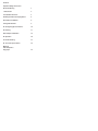
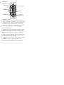
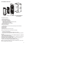
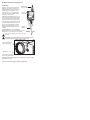
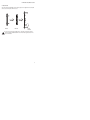
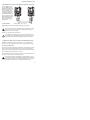
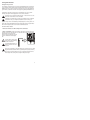
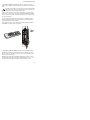
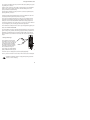
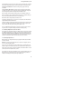
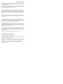
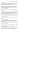
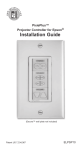
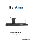
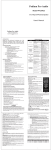
PixiePlus™
Device Control Module
Installation Guide
(Decora™ wall plate not included)
Patent US 7,334,067
PXE-DCM+
PXE-DCM-BLUE+
PXE-DCM-AMBER+
PXE-DCM-GREEN+
Contents
Important Safety Instructions
Electrical Warning
1
I. Introduction
2
II. Installation Overview
3
III. Wiring PixiePlus to Display Device
4
IV. PixiePlus Installation
5
V. Program PixiePlus
9
VI. Configuring Special Features
14
VII. Cloning
17
VIII. Complete Installation
19
IX. Operation
20
X. Troubleshooting
21
XI. Technical Specifications
22
Warranty
FCC Compliance
Copyright
23
Important Safety Instructions
1) Read these instructions.
2) Keep these instructions.
3) Heed all warnings.
4) Follow all instructions.
5) Do not use this apparatus near water.
6) Clean only with dry cloth.
7) Do not block any ventilation openings. Install in accordance with the manufacturer's instructions.
8) Do not install near any heat sources such as radiators, heat registers, stoves, or
other apparatus (including amplifiers) that produce heat.
9) Do not defeat the safety purpose of the polarized or grounding type plug. A polarized plug has two blades with one wider than the other. A grounding type plug has
two blades and a third grounding prong. The wide blade or the third prong is provided for your safety. When the provided plug does not fit into your outlet, consult
an electrician for replacement of the obsolete outlet.
10) Protect the power cord from being walked on or pinched particularly at plugs,
convenience receptacles, and the point where they exit from the apparatus.
11) Only use attachments/accessories specified by the manufacturer.
12) Use only with a cart, stand, tripod, bracket, or table specified by the manufacturer, or sold with the apparatus. When a cart is used, use caution when moving the
cart/apparatus combination to avoid injury from tip-over.
13) Unplug this apparatus during lightning storms or when unused for long periods
of time.
14) Refer all servicing to qualified service personnel. Servicing is required when the
apparatus has been damaged in any way, such as power-supply cord or plug is
damaged, liquid has been spilled or objects have fallen into the apparatus, the apparatus has been exposed to rain or moisture, does not operate normally, or has
been dropped.
WARNING - To Reduce the Risk of Fire Or Electric Shock, Do Not Expose This Apparatus To Rain Or Moisture.
Apparatus shall not be exposed to dripping or splashing and no objects filled with
liquids, such as vases, shall be placed on the apparatus.
Electrical Warning
The PXE-DCM+ is a low-voltage device. Never install the PixiePlus in an electrical
back box containing high-voltage wiring. This would cause a serious electrical
danger and violate United States national electrical codes.
1
I. Introduction
Mounting Screws
IR Transmitter
IR Learning Window
Insert Modules
Status LED
PixiePlus Board
Learning Mode
Activation Switch
Easy Setup and Configuration
The PixiePlus (PXE-DCM+) is a single-gang AV control device. The modular button
interface is easily customizable and enables control of almost any display device.
The PixiePlus is field-programmed in minutes using IR-learning technology. Multiple
units may be quickly and easily configured using wireless cloning technology.
The PixiePlus may be configured with an Inactivity Shutdown Time (pg. 14) to protect bulb life, or with a Security Lock (pg. 16) to prevent unauthorized use.
Controls One or Multiple Devices
One PixiePlus can control multiple devices through IR. The PixiePlus can control
multiple units of the same device, or different models. The PXE-DCM+ ships with
one RS232/IR transmitter. Additional units may be ordered separately (part no.
PXE-EMIT-232/IR). One PixiePlus can drive as many as ten 232/IR transmitters.
The PixiePlus can control devices with RS232 as well as IR. Use of RS232 requires
the PixiePlus Programming Wand (PXE-PGM-TOOL, sold separately). See Programming Wand documentation for more information.
The PixiePlus is designed for use with a Leviton Decora™ wall plate (not included).
The PixiePlus may be installed in a single-gang back box (not included).
Bezels are available in black (PXE-BEZEL-BL) and gray (PXE-BEZEL-GR).
2
II. Installation Overview
Bezel
Inserts Circuit Board Single-Gang Wall Box
(not included)
The PixiePlus ships with:
- 1 PixiePlus Circuit Board
- 7 White Plastic Button Inserts
- 1 Cable Assembly consisting of:
1 Plastic Cable Assembly Block
1 RS232/IR transmitter module (PXE-EMIT-232/IR)
1 6VDC Regulated Power Supply
Double-Sided Tape (attached to Block)
- IR Emitter Cable Anchors
- 2 Bezels (ivory and white)
- 1 3-position Captive Screw Connector for power/signal out from PixiePlus
- Instruction Manual
- Quick Start Guide
- Mounting Screws
- Paper Clip (for setting to IR-learning mode)
Required and Optional parts and accessories (not included)
- 1 3-conductor Cable (Required)
- 1 Leviton Decora™ wall plate (Required. Match to bezel color.)
- 1 Single-Gang Back Box (Optional. SP Controls recommends using a grounded
back box)
- Additional RS232/IR transmitter for control of additional display devices (Optional,
requires PXE-PGM-TOOL for RS232)
- PixiePlus programming tool (PXE-PGM-TOOL) for configuring the PixiePlus with
RS232 codes or realtime scheduling events
- PixiePlus Real-Time Clock (PXE-DCM-RTC): Allows the PixiePlus to perform
scheduled events, such as locking or powering devices off.
- Bezel Inserts Circuit Board Single-Gang Wall Box (not included)
NOTE: The PXE-EMIT-232/IR will not work with the PXE-DCM Pixie, nor can it be
used in combination with the PXE-EMIT.
3
III. Wiring PixiePlus to Display Device
Installation
1. Wire Cable Assembly Using the three-conductor cable, wire the cable assembly block to
the corresponding positions on the PixiePlus
captive screw connectors (+6V, GND, BUS).
A two-wire RS232 output splits off from the IR
emitter at the clamshell assembly. For instructions on wiring and configuring the PixiePlus
with RS232, see documentation for the optional part PXE-PGM-TOOL (required for use
of RS232).
6 VDC
300mA
BUS Activity
BUS
+6V
Connect
6V DC
POWER
IR Emitter to IR
Receiver Window
GND
Position the clamshell cable assembly at the
display device you wish to control. Wire the
cable assembly to the PixiePlus using a threeconductor cable (not included). We recommend using 18-, 20-, or 22-gauge stranded
copper wire cable, such as standard audio
cable (Belden. 8451 or 9451).
3-conductor to
PixiePlus
2. Position IR Bud over receiver window of
display device Remove the emitter backing to expose the
adhesive and secure the bud to IR receiver window.
Some devices are extremely sensitive to precise bud
placement.
The IR emitter bud does not illuminate when it sends signal, though the
IR Activity LED will illuminate on the cable assembly clamshell .
Affix IR emitter to device
with included anchors
Affix bud to IR receiver
3. For a more secure assembly, anchor RS232-IR transmitter clamshell to display
device with included anchors.
4. Affix the IR cable assembly block to the AV display device using the included
double-sided Velcro tape.
5. Connect 6 VDC power supply to IR cable assembly block.
4
IV. PixiePlus Installation
Select the button insert modules that match the design of your remote control. For
example, if your remote control has a single toggling power button, select the Toggling Power module.
Each button can be programmed to send as many as four commands, as a macro
(all at once) or in round robin.
1. Assemble Insert Modules
4-Button Source modules are available in two options:
1) COMP, VID, SYNC, MUTE
2) Blank, MUTE, Ch UP, Ch DN
Note: You must chose one and only one insert module of each type, i.e. you cannot
use two source insert modules and no volume module.
Included Insert Modules
Customized silkscreened button modules are also available; contact SP Controls for
more information.
Toggling
Toggling
Control
Discrete
Discrete
(2-Button)
Discrete
(4-Button)
Blank
5
IV. PixiePlus Installation cont’d
2. Attach Bezel
After selecting the appropriate insert modules, place them against the circuit board
and secure them in place with the bezel.
Bezel
Inserts
Pixie
Board
Be sure the bezel is placed right side up - otherwise it may block the programming window and Status LED. The SP Controls logo should be in the
correct orientation.
6
IV. PixiePlus Installation cont’d
3. Wire Controller
Connect the 3-conductor cable to the captive screw connector on the back of the
PixiePlus. Be sure that the wires match the connections on the cable assembly
block end - the PixiePlus uses crossover wiring.
+6V
BUS
GND
BUS
+6V
GND
Wire landing must match
landing on cable assembly
block at the display device
side (see pg. 4).
Verify the captive screw connectors are fully open before inserting the wires.
It is possible to physically anchor the wires without making a solid electrical
connection if they are turned the wrong way.
7
IV. PixiePlus Installation cont’d
4. Wire Additional Assemblies to Control Multiple Display Devices (Optional)
To control multiple devices,
wire each additional PXEEMIT-232/IR in parallel to the
PixiePlus. Each position on
the PixiePlus barrier strip
must be wired directly to the
corresponding position on
the PXE-EMIT-232/IR barrier
strip. For example, the PXEEMIT-232/IR position labeled
+6V must be wired to the
PixiePlus barrier strip position labeled +6V.
5. Install Controller
Wired in parallel: +6V to +6V, etc.
Optional: Mount the PixiePlus to a single-gang wall box (not included).
The inner screw holes on the PixiePlus should be used to anchor the unit to
the wall box. The outer screw holes will be used to affix a Decora™ wall
plate over the face of the PixiePlus.
Plug in the 6V wall wart to power the PixiePlus.
The PXE-DCM+ is a low-voltage device. Never install the PixiePlus in an
electrical back box containing high-voltage wiring. This would cause a serious electrical danger and violate United States national electrical codes.
6. Toggling Source Module between 2-Button and 4-Button Mode (optional)
By default, the PixiePlus is configured to work with a one- or two-button source
module. To use a four-button source module, you must enable four-button mode.
To enable four-button mode:
Assemble the PixiePlus, including a four-button module, as described in Section IV
above. Press and hold any single button in the source selection module while inserting a paper clip into the programming aperture. The PixiePlus should beep three
times to indicate that four-button mode is now active.
The PixiePlus will now be in Learning Mode (see below). You may program the PixiePlus or, to exit learning mode, remove the paper clip.
When four-button mode is enabled, both the left and right sides of any oneor two-button module button should illuminate separately when a source button is pressed, not in unison. If two neighboring buttons on the four-button
pad illuminate simultaneously, the unit is NOT in four-button mode.
8
V. Program PixiePlus
IR Programming Overview
The PixiePlus controls AV devices by learning and duplicating the IR codes of their
remote controls. A single button may be programmed with as many as four codes.
Multiple codes may be sent as macros or round robin. (If you’ll be using RS232 on
your PixiePlus, consult the manual for the Programming Wand (PXE-PGM-TOOL).
To program the PixiePlus you will set it to Learning Mode, arm each key for IR
learning, and squirt it with the appropriate remote control commands.
Any button may be programmed with any code – it does not have to be the
same as the code silk-screened on the button.
To program a four-button Source module, the PixiePlus must be configured
to four button mode (see PixiepPlus installation Section 6 on Page 8).
If you are using a device manufactured by Philips, Magnavox, or Koss, please consult the SP Controls PXE-DCM Philips Protocol Application Note for special instructions. Visit the support section of our web site to find that document.
To learn a remote control:
1. Power the PixiePlus: the LED backlights will be illuminated.
2. Enter Learning Mode: Gently insert a paper clip into the small hole labeled "insert paper clip to enter learning mode". The PixiePlus will remain in Learning Mode
while the paper clip remains in the
aperture. Removing the paper clip will
return the PixiePlus to normal operation.
Be gentle with the paper clip to
ensure that you do not damage
the switch mechanism.
The Status LED will blink red
while the PixiePlus is in learning mode.
If the room is too bright, the PixiePlus will not enter learning mode. The LED
will glow solid red, the buttons will beep continually when pressed, and they
will not arm for learning. Darken the room or shield the PixiePlus from the
ambient light while learning. Direct sunlight is always too bright.
9
V. Program PixiePlus cont’d
3. Test Remote and Identify Sweet Spot: Position the remote control a few inches
from the IR learning eye (upper right of PixiePlus front).
When you press a key on the remote, the PixiePlus status LED should flicker. As
you move the remote closer or farther from the receiver window, or move off axis
the red flashes will dim and become intermittent. Find a position that consistently
yields clear, regular blinking. This is the "sweet spot".
If you do not see the Status LED flicker rapidly, your remote may need new
batteries.
Some remotes have several emitting LEDs, which may not be located in the
center of the remote.
4. Round Robin Codes and Macros
Each PixiePlus button may be programmed with either a single command or multiple commands (as many as four). Multiple commands may be sent round robin or
as macros. Round robin buttons send one command per button press. Each time
the button is pressed, it sends the next code in the series. Macro buttons send all
programmed codes each time the button is pressed.
Example - Round Robin: The SOURCE toggle button may be programmed with
four round robin commands to switch between four inputs on the display device.
The single SOURCE button is programmed with all four input commands, and configured to Round Robin mode. Each time the SOURCE button is pressed, it sends
one of the four commands, in the order learned.
Example - Macro: The COMP input button may be programmed with two commands and configured to macro mode. The COMP button is programmed so that
each time it is pressed it sends the RGB1 input command, followed by the autosync
command.
RGB1
RGB
Video
Video
Remote Control
Source Module
10
V. Program PixiePlus cont’d
5. To program a button with a single code: While the PixiePlus is in learning
mode, press the button to be programmed to arm it. It should beep once and slowly
blink.
If the button beeps loudly as soon as you press it, check if the Status LED is
solidly lit. If it is, there may be too much light in the room. Reduce the ambient light level or shade the PixiePlus and try again.
Hold the remote control in the sweet spot you found in step 3. Press and hold the
button on the remote for about a second. The status LED should flicker, indicating
that the code is being received. The PixiePlus will beep three times quickly to indicate successful learning.
You may press a different button for learning at any time, including buttons that
have already been programmed. If you press a button that is already armed for
learning a second time, it will be disarmed.
If the PixiePlus learns the code the button will begin flashing rapidly in VERIFICATION MODE. Go to Step 7, Verify Learned Keys.
6. To program a button with multiple codes for macro or round robin commands: Put the PixiePlus in learning mode. Quickly press the button you wish to
program one time for each code you want it to learn. The PixiePlus will beep once
for each code it expects to learn.
Example: If you wish to program a SOURCE button with three codes, set the PixiePlus to learning mode and quickly press the SOURCE button three times. The
PixiePlus will beep three times to indicate it is ready to learn three codes.
11
V. Program PixiePlus cont’d
The armed key will indicate it is ready to learn the first code by flashing once, pausing, flashing once, and so on.
Hold the remote control in the sweet spot you found in Step 3. Press and hold the
button on the remote for about a second. The PixiePlus will beep three times
quickly to indicate successful learning.
Now the button will indicate it is ready to learn the second code by flashing twice,
pausing, flash twice, and so on.
Program the button, and it will again beep three times to indicate if the code was
successfully learned. Repeat as many times as necessary.
When you have programmed the last code in the series, the PixiePlus will beep
quickly three times to indicate the code is successfully learned, and then beep
slowly three more times to indicate that the button has been fully programmed.
Arming will eventually time out if no IR code is received. You may select a different
key for learning at any time, including keys that are already learned.
If the PixiePlus successfully learns the code the key will begin flashing quickly to indicate it is in VERIFICATION MODE.
You cannot add a new code to a key that is already programmed. You must reprogram it entirely. If any code fails, the learning sequence for that key is started over.
By default, any button that has been programmed with multiple codes will send
them round robin. To set a button to macro mode, first verify the code, then go to
Step 8.
7. Verify Learned Keys:
If the PixiePlus is wired to control
the display device before programming, you can verify each code was
successfully learned immediately
after programming it. Each button
will remain in verification mode for
20 seconds before timing out.
After learning, each button will blink
rapidly to indicate that it is ready for verification. Press the button, and the PixiePlus
will emit the code. The display device should respond appropriately.
If the key is set to round robin or macro mode, it will send the codes as configured.
Verification is particularly useful for verifying that repeating codes work
properly (i.e. volume ramping).
12
V. Program PixiePlus cont’d
If the button did not seem to learn correctly, press any other button on the PixiePlus,
then press the target button again to rearm it, and repeat the learning procedure.
8. Repeat for Each Button: While still in learning mode, program and verify
each button.
9. Set a button to Macro Mode: If a button has been programmed with multiple
commands, the button may be configured to send all commands with a single button press. By default, buttons are configured to Round Robin mode.
After verification, and while still in learning mode, press and hold the button you
wish to set to Macro mode for approximately five seconds. The PixiePlus will beep
three times to indicate that it has now been set to Macro mode.
Each button must be independently set to Macro mode.
If a button is reprogrammed or the entire device is erased, the code will automatically default back to Round Robin mode.
A button set to Macro mode that is pressed and held will repeat only the last code in
the macro. The button will send only one instance of each code, except the final
code. The final code will repeat for as long as the button is held.
There is a 600 millisecond delay between each code in the series. Some devices
may not be able to respond to multiple commands sent this frequently.
10. Controlling Multiple Units of the Same Device
One PixiePlus may send identical codes to multiple units of the same device without
any additional configuration. For example, you may control two identical projectors
with a single PixiePlus by adding an additional IR emitter and wiring it from the PixiePlus to a second projector. A single button press on the PixiePlus will send identical codes to both devices, and the PixiePlus will control them in tandem.
11. Controlling Multiple Devices
Different buttons on a single PixiePlus may be programmed with codes from different remote controls.
Example: You wish to control power and source selection on a projector, and volume on an IR-controllable amplifier.
To do so, wire one IR emitter to the LCD monitor and the second IR emitter to the
amplifier. Program the PixiePlus power and source buttons with the codes from the
LCD monitor remote control. Program the PixiePlus volume buttons with the volume
control codes from the amplifier remote control.
One PixiePlus may learn IR commands from remote controls from different devices.
Each button can be configured to send a single command (normal operation) or
multiple commands (macro mode) with a single button press.
13
V. Program PixiePlus cont’d
Example: You wish to configure the PixiePlus to send a power command to a projector and a separate power command to an amplifier with single press of the PixiePlus POWER ON button.
To do so, program the PixiePlus POWER ON button with two commands, Power On
from the projector remote, and Power On from the amplifier remote. Then configure
the PixiePlus POWER ON button to Macro mode.
12. To Erase All Buttons: Set the device to Learning Mode. Press and hold any
two buttons to erase the PixiePlus. The whole keypad will blink, first slowly, then
quickly. Then all buttons will go dark and the PixiePlus will beep four times, indicating that it has been erased. Once a device has been erased there is no way to unerase it.
13. To Exit Learning Mode: Gently remove the paper clip to exit Learning Mode.
Be sure not to hold any buttons while removing the paper clip, or the unit will be set
to cloning mode.
14. Final Test of Learned Codes: Verify that the IR emitter bud has been placed
directly over the IR detector on the device the PixiePlus controls. Press the PixiePlus button that you wish to test. A red LED labeled “IR Activity” will blink when
the code is being sent, but the emitter bud does not illuminate.
15. Troubleshooting: If you cannot control the device, be sure that the emitter bud
is positioned correctly. If some buttons work but others do not, try re-programming
the buttons that do not work. Make sure that you press the button on the remote for
at least one second during learning.
Fluorescent lights can interfere with IR signals. Check if the projector is close to a
fluorescent light source. If so, try turning off the lights. If this restores control, cover
the IR emitter bud and display device IR receiver window with an IR-opaque shield,
such as gaffer's tape.
See Section X. Troubleshooting beginning on page 21 for more tips.
VI. Configuring Special Features
1. Configuring the Inactivity Shutdown Timer
The Inactivity Shutdown Timer will automatically shut the display device down if it is
not used for a configurable length of time.
Example: The PixiePlus Inactivity Shutdown Timer is set to three hours. If no button
is pressed on the PixiePlus for three hours, the PixiePlus will begin to beep and
flash in warning 120 seconds before three hours has elapsed. If no button is
pressed, at three hours the PixiePlus will send all codes programmed to the
POWER OFF button.
14
VI. Configuring Special Features cont’d
Use of the Inactivity Shutdown Timer requires the DISCRETE POWER ON/POWER
OFF keypad module.
Configuration of the Inactivity Shutdown Timer requires the VOLUME UP and VOLUME DOWN keypad module to be inserted. The volume module can be replaced
with a blank after the feature is configured.
What the Timer does
- The timer begins counting down immediately after the PixiePlus powers on a display device. Pressing any button except POWER OFF resets the timer and it begins
timing down again. Pressing POWER OFF stops the timer. There is no visible behavior when the timer is counting down, until two minutes before it expires.
- If the timer counts down to 120 seconds, the PixiePlus will begin beeping and the
POWER OFF button flashes to warn users that it is preparing to shut down.
- If the timer expires, the system shuts itself down exactly as if the user had pressed
the POWER OFF key. Any macro programmed for POWER OFF is executed. If the
Security Keylock feature is enabled, the PixiePlus will also lock.
To set the Inactivity Shutdown Timer
Press and hold both volume keys while gently inserting a paper clip in the programing aperture of the PixiePlus.
Be gentle with the paper clip to ensure that you do not damage switch
mechanism.
The PixiePlus will begin beeping to communicate the current Timer setting (described in the table below).
To change the active setting: Press VOLUME UP or VOLUME DOWN to cycle to
the next setting. The PixiePlus will indicate the new setting with a pattern of beeps,
and update its Red LED blinking.
When you have reached the desired setting, remove the paper clip to return to normal operation.
Inactivity Shutdown Timer Settings
PIXIEPLUS AUDIO
PIXIEPLUS STATUS LED TIMER SETTING
ONE LONG BEEP
ONE QUICK BEEP
TWO QUICK BEEPS
THREE QUICK BEEPS
FOUR QUICK BEEPS
FIVE QUICK BEEPS
SIX QUICK BEEPS
SEVEN QUICK BEEPS
EIGHT QUICK BEEPS
LED dark
LED blinks once
LED blinks twice
LED blinks three times
LED blinks four times
LED blinks five times
LED blinks six times
LED blinks seven times
LED blinks eight times
Timer DISABLED (default)
One-hour shutoff
Two-hour shutoff
Three-hour shutoff
Four-hour shutoff
Five-hour shutoff
Six-hour shutoff
Seven-hour shutoff
Eight-hour shutoff
15
VI. Configuring Special Features cont’d
2. Security Keylock
The Security Keylock locks the PixiePlus during disuse to prevent unauthorized
use. It disables the keys on the PixiePlus after POWER OFF is pressed, until a Security Keycode is entered on the standard PixiePlus keypad. If the proper code is
not entered, the system cannot be turned on or used.
Use of the Security Keylock feature requires the DISCRETE POWER ON and
POWER OFF keypad module to be inserted. If your device remote has only a “toggling power” key, you may still use this module if you program both POWER ON
and POWER OFF with the same (toggle) code.
How the Security Keylock Works
When POWER OFF is pressed, the PixiePlus enters a “locked” state and all keypad
buttons go dark.
When the system is locked, any button press other than POWER ON is understood
as a Security Keycode entry. A soft chirp is emitted, but the key does NOT illuminate
and no control operation is performed. If the correct code sequence is entered, the
system unlocks, the interface illuminates, and normal operation is restored until the
next time POWER OFF is pushed and the system locks again.
If the entered code is not correct, the system emits a long beep and remains locked.
Security Keycodes may be one to six button presses long. Codes can use any key
on the keypad other than POWER ON.
By default the Security Keylock feature is off, and the default Security Keycode is
OFF-OFF-OFF.
To Configure the Security Keylock
1. Press and hold both POWER ON and POWER OFF while gently inserting a
paper clip into the PixiePlus programming aperture. The PixiePlus will enter “Security Keylock configuration mode” and communicate the current Security Keylock settings as follows:
- The Red Status LED indicates whether the Security Keylock feature is enabled
(LED is on) or disabled (LED is off).
- The PixiePlus will show the existing Security Keycode by illuminating each button
in the code in sequence, pausing briefly, then repeating the code.
2. To enable or disable the Security Keycode feature, press POWER ON to toggle
between enabled/disabled.
3. To change the Security Keycode, enter a new code by pressing a sequence of up
to six keys, using any keys in any combination, except POWER ON. After the code
is entered, the PixiePlus will immediately show the new Security Keycode.
16
VI. Configuring Special Features cont’d
If more than six keys are entered, the PixiePlus will beep and reset to the previously
configured code.
4. After the new Security Keylock has been reconfigured, its new settings must be
confirmed. If you do not follow this sequence to store the new settings, any changes
you make will be discarded when you leave Security Keylock configuration mode.
To confirm the new settings, press POWER ON and hold it down until the PixiePlus
beeps three times.
5. After the new code is set and confirmed, carefully remove the paper clip as usual
to return to normal operation.
If the Security Keycode is forgotten, you can retrieve it by putting the PixiePlus back in Security Keycode configuration mode – it will then display
the currently-configured code.
3. Configure PixiePlus Audio Feedback
By default, the PixiePlus clicks when a button is pressed. To mute, press and hold
any button while inserting a paper clip into the programming aperture. The PixiePlus
will beep quickly three times to indicate that AUDIO has been set to OFF.
VII. Cloning
Any PixiePlus may quickly and easily copy all the codes from any other PixiePlus.
The PixiePlus cannot clone a Pixie.
In cloning there is a donor unit and a recipient unit. The donor unit must already be
programmed with the appropriate codes (see Section V). The recipient will copy the
donor unit’s codes.
Both units must have the same button insert types, though they may be of different
colors.
Both units must be powered. The donor unit should be installed before beginning.
To power the recipient you may wish to temporarily daisy-chain power from
the terminal block of the donor unit with a short length of cable
17
VII. Cloning cont’d
Cloning Procedure
1. Set the recipient to cloning mode. If the PixiePlus has never been programmed,
you may set it to cloning mode by pressing and holding any button while applying
power. If a PixiePlus has previously been programmed, gently insert a paper clip
into the IR Learning aperture of the recipient unit. Press and hold any button on the
that unit and, while still holding the button, remove the paper clip. The PixiePlus will
rapidly chirp while in cloning mode.
It will time out of cloning mode in about 15 seconds, so have both devices on hand.
If the PixiePlus times out of cloning mode, repeat this procedure to return it to
cloning mode.
approx. one inch apart
facing each other
2. Position the two units face-to-face, with both units held upright, approximately
one inch apart. They should be directly across from each other with the bezels lined
up. This will position the IR receiver window of the cloning PixiePlus directly across
from the IR transmitter in the donor PixiePlus.
Be sure not to obstruct the IR receiver window or transmitter with your
hands.
18
VII. Cloning cont’d
When the units are correctly lined up, the donor PixiePlus will automatically enter
cloning mode. Its Status LED will turn solid red and both units will chirp rapidly.
3. Hold the recipient steadily in front of the donor. If the connection is broken (the
recipient ceases to chirp), reposition the recipient unit to re-establish communication and the units will continue where they left off. If communication is broken for
more than 15 seconds, the recipient will time out of cloning mode and you will need
to begin again.
4. When the recipient has completed copying codes from the donor, it will beep 3
times and reset. After the PixiePlus has reset it will be fully operational with the
same codes and configuration settings programmed into the donor unit.
After cloning is complete, the donor unit will remain in cloning mode for 15 seconds
until it times out. It will then return to normal operation.
VIII. Complete Installation
To complete the installation, secure a Leviton Decora™ wall plate (not included) over the face of the
PixiePlus. The outer screw holes on the PixiePlus
should be used to secure the wall plate.
19
IX. Operation
Power
Power buttons control power on the projector or monitor. The PixiePlus is always
on, and its LED backlit buttons remain continually illuminated, unless the Security
Keylock is active.
Toggling
Discrete
Source
Source button inserts control input selection on the projector or monitor.
Toggling
Discrete
(2-Button)
Discrete
(4-Button)
Volume
If the PixiePlus is not used to control volume, a blank button insert may be used.
Control
Blank
20
X. Troubleshooting
Programming Problems
Verify that the PixiePlus is in learning mode for programming. The Status LED continually blinks red when the PixiePlus is in learning mode.
The Status LED is solid red and the PixiePlus beeps loudly each time you try to arm
a key for learning.
The ambient light is too bright. Shield the PixiePlus from ambient light sources and
try to re-program.
If the buttons appear to program properly but do not control the device, verify each
code is correctly learned immediately after it has been programmed. The button will
blink rapidly to indicate it is in verification mode. Push the button and the IR emitter
will emit the corresponding code.
When the PixiePlus is emitting a code in verification mode, you should see the Status LED flicker at a consistent strength and frequency. If the flickering seems uneven, verify that you are holding the remote control in the correct ’sweet spot’ and
described in Section V, Part 3.
If the Status LED does not flicker rapidly when the remote control is emitting a code,
verify that the batteries in your remote control are fresh.
The PixiePlus beeps three times as soon as the paper clip is inserted into the programming aperture.
The PixiePlus beeps three times when it is toggled between two-button and fourbutton Source Selection modes. This is done by pressing and holding any button
while inserting the paperclip. Is one of the buttons being activated while the paper
clip is being inserted?
This can happen if a button is stuck – check all buttons to make sure they are not
caught in a depressed position. If not, it is possible that the button contacts on the
PixiePlus circuit board are being shorted. Remove the bezel and check for solder or
bits of wire that could bridge the button contacts. Then reseat the buttons, re-attach
the bezel, and try entering programming mode again. If this does not correct the
problem, please contact SP Controls Technical Support.
Operation Problems
The PixiePlus does not power the projector/monitor on.
Is the PixiePlus display dark, and does it chirp when any button is pressed? If so,
the PixiePlus Security Keylock is active. See page 16 for information on how to configure and/or retrieve the Security Keylock code.
If the Security Keylock is not set, verify that the projector or monitor powers on normally with its own remote control or settop controls. If it does not, it may not be
plugged in or may require service.
21
X. Troubleshooting cont’d
The PixiePlus does not control the projector/monitor.
Be sure that the code was programmed correctly – try reprogramming the unit.
Confirm that the IR emitter bud is positioned directly over the receiver on the IR window of the device you are controlling. Some devices are sensitive to accurate
placement.
Fluorescent lights can interfere with IR signals. Check if the projector is close to a
fluorescent light source. If so, try turning off the lights. If this restores control, cover
the IR emitter bud and display device IR receiver window with an IR-opaque shield,
such as gaffer's tape. Some opaque tapes do not block IR.
The device will not switch to one of the inputs.
Some display devices will not switch to certain inputs if there is no signal present
Control is intermittent.
If you are using a device manufactured by Philips, Magnavox, or Koss, please consult the SP Controls PXE-DCM Philips Protocol Application Note for additional programming instructions.
If you are still unable to control your device, please contact SP Controls Technical
Support for further assistance.
XI. Technical Specifications
Package Type
Single-Gang Decora™ Mounting
Dimensions
4.130” (h) x 1.745” (w) x .90” (d)
Weight (PCB with bezel and 3
insert modules)
2.5 oz
Power Supply
6VDC, 300mA
Output Type
IR Emitter/RS-232 (programming RS232
commands requires PXE-PGM-TOOL, sold
separately)
Recommended Wire
18- to 22- Gauge 3-conductor stranded copper
wire
The PixiePlus is UL listed and CE certified.
22
Warranty
SP Controls warrants all PixiePlus products and accessories against defects in materials and workmanship for a period of five years from the date of purchase.
Although SP Controls thoroughly tested and reviewed this documentation, there is
no warranty, express or implied, with respect to quality, merchantability, or fitness
for a particular purpose. Therefore, the PixiePlus and accessories are provided "asis" and the purchaser assumes the entire risk as to quality and performance.
There are no obligations or liabilities on the part of the SP Controls Corporation for
consequential damages arising out of or in conjunction with the use or performance
of these products or other indirect damages with respect to loss of profit, revenue,
or cost of removal and/or replacement. Some states do not allow the exclusion or
limitation of incidental or consequential damages, so the above limitation or exclusion may not apply to you. This warranty gives you specific legal rights, and you
may also have other rights that vary from state to state. SP Controls' maximum liability shall not exceed the price paid by the user.
All implied warranties, including warranties for merchantability and/or fitness, are
limited in duration to three (3) years from the date of purchase. Proof of purchase
must be provided with any claim.
FCC Compliance
This equipment generates radio frequency energy and if not installed in
accordance with the manufacturer's instructions may cause radio interference.
This equipment complies with part 15, Subpart J of the FCC rules for a Class A
computing device. This equipment also complies with the Class A limits for radio
noise emission from digital apparatus set out in the Radio Interference Regulation
of the Canadian Department of Communications. These above rules are designed
to provide reasonable protection against such interference when operating the
equipment in a commercial environment. If operation of this equipment in a residential area causes radio frequency interference, the user and not SP Controls, Inc.,
will be responsible.
COPYRIGHT
Pixie™, PixiePlus™, and the SP Controls switch logo are trademarks of SP Controls, Inc. Decora™ is a registered trademark of Leviton Manufacturing Co. All other
trademarks mentioned in this manual are the properties of their respective owners.
No part of this document may be reproduced or transmitted in any form or by any
means, electronic or mechanical, for any purpose, without express written permission of SP Controls, Inc.
© 2010 SP Controls, Inc. All rights reserved.
Changes or modifications made to this equipment not expressly approved by SP
Controls, Inc., could void the user's authority to operate the equipment.
SP Controls, Inc. assumes no responsibility for any errors that appear in this document. Information in this document is subject to change without notice
23