1
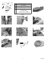
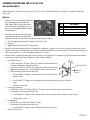
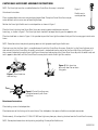
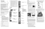
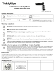
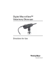
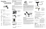
LS-135 & LS-150 Halogen Exam Lights INTRODUCTION Thank you for purchasing your new Halogen Exam Light by Welch Allyn, the worldwide leader in illuminated medical diagnostic instrumentation. By following the use and care guidelines given in this booklet, you will enjoy years of dependable, trouble-free service from your new exam light. This exam light can be used for topical examinations of the skin such as abrasions, foreign body removal, and other similar applications. WARNINGS & CAUTIONS CAUTION: All users of this exam light should be thoroughly trained in the medical examinations appropriate to the equipment. Furthermore, they should read and understand the instructions contained within this manual before use. Failure to do so may result in injury to the patient or damage to the equipment. CAUTION: Do not use the LS-135 or LS-150 for transillumination, as erythema may result. Contact Welch Allyn regarding appropriate lights for transillumination applications. INTENSE LIGHT: Lamp is extremely bright. Do not stare at the lamp when in use. May be harmful to eyes. CAUTION: Remove power cord from electrical outlet and allow lamp to cool 10 minutes before replacing with Welch Allyn lamp. For the LS-135 use lamp No.: 04430 and for the LS-150 use lamp No.: 04450. DANGER: Electric Shock Hazard - do not disassemble the instrument. Refer servicing to qualified service personnel. There are no user serviceable parts other than the lamp. CAUTION: Use the examination light in its intended working range of 12 to 36 inches. Exposures at closer distances may be harmful to skin. DANGER: Risk of explosion if used in the presence of flammable anesthetics. IPXØ: Not protected against the ingress of water. HOT SURFACE: Lamp surface is hot. May be harmful to skin if touched. 1 443191FAX Guidelines for the safe use of the LS-135 & LS-150 include: General good practices to minimize risk of harm to the skin from optical radiation hazards include: minimizing illumination intensity at the tissue examination site, minimizing exposure times, and taking additional precautions when skin sensitivity has been altered through tissue trauma or the use of anesthesia. General good practices to minimize risk of harm to the eyes from optical radiation hazards include: avoiding looking at bright light sources and their reflections, and protecting eyes where normal pupil sizes and aversion responses are not present. SWITCH: Switch operation is described as follows: Off position when rocker switch is oriented towards this marking. On or full light intensity position. On or low light intensity position (LS-135 only). NOTE: This product complies with current required standards for electromagnetic interference and should not interfere with other equipment or be affected by other compliant devices. As a precaution, avoid using this device in close proximity to other equipment. ASSEMBLY INSTRUCTIONS FOR LS-135 & LS-150 FLOOR STAND MODELS NOTE: Follow the assembly instructions listed below and their corresponding photographs. Required tools for assembly: Phillips #2 or #3 screwdriver. 1. Remove all items from the shipping carton. Check for damage or missing components. Refer to photo 1 and table 1. Notify Welch Allyn, or your nearest Service Center of any damage or missing parts using the appropriate phone number listed on the back. 2. Using the shipping box as an assembly aid; place the base (item 1) on its side oriented in the box as shown in photo 2a. 3. Obtain the pole (item 3). Identify and orient the pole’s flange end with wire harness to the base and feed wire harness through base center hole as shown in photo 2b. Align wire harness into notch in base as shown in photo 3, then seat pole into base. EXERCISE CARE WHEN INSERTING POLE AND HARNESS INTO BASE. DO NOT PINCH WIRES. 4. Connect pole’s wire harness connector to the corresponding connector in the base as shown in photo 4. Align and press firmly into place. 5. From the parts kit, obtain the base cover plate and attach the remaining wire connector to the corresponding tab located on the cover plate. Refer to photo 5. 6. From the parts kit, obtain the screw and external lockwasher and install through the plate, place the plate into the base, threading screw clockwise into pole. Tighten firmly, using screwdriver. Refer to photo 6. 7. With the base/pole still lying on its side, gently pull the electrical connector from inside of the pole using the twist tie. Remove and discard twist tie. Refer to photo 7. Orient the Luminaire-flexible arm assembly’s electrical connector to the remaining pole electrical connector and connect each by firmly pressing together. Refer to photo 8. 8. Connect the flexible arm to the pole by lining up the slots on the black plastic connector (nearest the electrical connector) above the pole cut outs. Push flexible arm into pole until it clicks into place. Refer to photo 9. 9. Prior to plugging the unit into the appropriate outlet, inspect the lamp to insure that it has not become unseated during shipment (Refer to photo 10). If the lamp is not properly seated in the lamp housing, use your fingertips to gently press against the protective cover glass of the lamp to spring the lamp back into the proper position. If the lamp can not be easily reseated by this method, refer to the Lamp Replacement instructions to open the Lamp Housing and reseat the lamp. 10. Stand light assembly up onto its base and plug into an appropriate outlet. Please refer to warnings and caution section as well as the operations section prior to use. 2 443191FAX No 3 1 2 2 1 4 3 4 #1 Description Base Assembly Luminaire-Flexible Arm Assembly Pole Assembly Parts Kit • Base Cover Plate • Screw 1/4-20 x 1” Phillips •1/4” External Lockwasher (443062-501) #2A Table #1 #2B #3 #5 #6 #8 #4 #7 Pole Cut Out #9 3 #10 443191FAX ASSEMBLY INSTRUCTIONS FOR LS-135 & LS-150 WALL MOUNT MODELS Required tools for assembly: Electric drill, 3mm (1/8”) and 4.7mm (3/16”) diameter drill bits, #2 phillips screwdriver, bubble level, linear scale. Wall Unit 1. Remove all items from shipping carton and check for damage. Refer to photo and table. Notify Welch Allyn or your nearest Service Center of any damage or missing parts using the appropriate phone number listed on page 9. 1 2 NO. Description 1 Light/Transformer Assembly Power Cord Mounting Hardware (443184-501) 2 3 2. Identify the type of wall construction you intend to mount the wall unit onto (and if applicable, transformer). Generally wall types can be described as follows: 3 • Dry wall (gypsum or plaster) with wood studs OR metal studs • Masonry • Wood (solid or heavy 19mm (3/4”) thick veneer) 3. Identify the desired location for light (and if applicable, transformer). In general, the wall unit must be installed so that at least two of its four fasteners extend into the walls structural members (studding or structural masonry). The cable length between the light and transformer is 1.1m (3.5’) and power cord length is 2.4m (8’). 4. Position the unit’s mounting bracket onto the wall and level. Using the bracket as a template, mark the four mount hole locations. Locate parts kit containing screws and plastic anchors. Mount as follows: • For studded dry wall: 1. Pre-drill two 3mm (1/8”) holes 19mm (3/4”) deep that are located over the structural studding (one side of the bracket). 2. Pre-drill two 4.7mm (3/16”) holes just through the drywall surface located opposite the previous holes. Install two plastic anchors into these holes. 3. Place mounting bracket over the holes and: Structural Stud Mounting Bracket • Install two #8-1.5” tapping screws through bracket and into the holes drilled in step 1. • Install two #8- 1.5” tapping screws through bracket and into the plastic anchors installed in step 2. • Tighten all four screws. • For masonry type walls: 1. Pre-drill four 4.7mm (3/16”) holes 38 mm (1.5”) deep. Install four plastic anchors into these holes. 2. Place mounting bracket over the holes and: • Install four #8-1.5” tapping screws through the bracket and into the plastic anchors installed in step 1. • Tighten all four screws. • For wood walls: 1. Pre-drill four 3mm (1/8”) holes 25 mm (1”) deep. 2. Place mounting bracket over the holes and: • Install four #8-1.5” tapping screws through bracket and into the wall. • Tighten all four screws. 4 443191FAX TRANSFORMER Mount the transformer to the wall using the hardware provided and integral brackets on the back of the transformer. Locate the transformer an appropriate distance from the light assembly, but within 2.4m (8’) from a suitable outlet. NOTE: For studded dry wall, identify a stud location (preferably on the same stud used to mount the light assembly). If a stud location is not available, you can use drywall only mounting as described below. 3. Place the transformer at the desired height and mark a short horizontal line corresponding to the top of the transformer. From this line, mark a vertical and plumb line down approximately 12cm (5”). 1.9 cm (3/4”) 8 cm (3 1/8”) 4. Mark hole location one 1.9 cm (3/4”) down from the horizontal line. Mark hole location two 8 cm (3 1/8”) down from hole location one. Refer to figure. • For dry wall over a stud or wood: 1. Pre-drill two 3mm (1/8”) holes 19mm (3/4”) deep that are located over the structural studding. 2. Screw two #8 1.5” tapping screws into wall allowing the screw heads to protrude 2.3mm (11/32”). • For dry wall only or masonry: 1. Pre-drill two 4.7mm (3/16”)holes just through the drywall surface or 38mm (1.5”) into masonry. Install two plastic anchors into these holes. 2. Install two #8-1.5” tapping screws into the plastic anchors allowing the screw heads to protrude 2.3mm (11/32”). OPERATION OF FLEXIBLE ARM Your new LS-135 & LS-150 light has been carefully designed to give you optimum performance to enable you to easily articulate and place the light exactly where you need it. These design attributes include: • The lamp has been offset at a 12° angle relative to the Luminaire housing, allowing the physician an unobstructed view of the field of interest. • A pole to flexible arm joint that allows the flexible arm to be freely rotated about the pole 270°. • A flexible arm to Luminaire joint that allows rotation of the Luminaire about the flexible arm 300°. • A 24” flexible arm that allows you to easily articulate and hold the Luminaire in an infinite number of positions. Please use the following guidelines for proper articulation of the flexible arm: • The flexible arm should be articulated (bent), NOT TWISTED. Twisting of the flexible arm beyond its rotation stops will decrease the life of the arm and can cause it to lose its ability to hold position. • Failure of the flexible arm due to twisting may void the warranty. Special Note: We recommend that you DO NOT acutely bend the flexible arm as shown to the right. LAMP REPLACEMENT Disconnect power cord from electrical outlet prior to replacement. Allow lamp to cool 10 minutes prior to replacement. 1. Exposing the Lamp (Refer to photo 1) • Turn power switch to the off (“ ”) position and unplug power cord from outlet. • Rotate Light Assembly so that the lamp points up (towards ceiling). • Completely loosen screw in Lamp Housing and lift to expose the Lamp . 5 443191FAX 2. Freeing the Lamp and Lamp Socket (Refer to photo 2) • Release the Lamp Retaining Wire from the Lamp Housing by pushing on wire “ears” towards Lamp Socket and swing out as shown to free the Lamp and Lamp Socket . 3. Removing the Lamp Socket (Refer to photos 3 and 4) • Hold the Lamp by its outer rim. Grasp the white sides of the Lamp Socket as shown, pull on the Lamp Socket while rocking it slightly to remove it from the Lamp . Do not pull on Lamp Socket Wires . 4. Install the new Lamp • Verify that the lamp number located on the metal plate inside the Light Assembly (photo #2) matches the replacement lamp number. • Replace Lamp and reattach Lamp Retaining Wire to Lamp Housing . • Align Lamp pins to Lamp Socket holes and reconnect Lamp Socket. • Reinstall Lamp Housing onto Light Assembly by first engaging Lamp Housing tab (opposite screw) into Light Assembly. Fully tighten screw. • Reconnect Power cord and verify Lamp operation. #1 #3 #2 #4 CLEANING 1. Unplug the unit prior to cleaning. 2. The entire unit can be wiped down with a cloth slightly dampened with a mild solution of detergent and water. Wipe the unit dry with a clean, dry cloth. Be careful not to allow moisture to enter into the unit or allow the plug prongs to get wet. 3. Do not plug the light back into the electrical outlet until the light is thoroughly dry. NOTE: Do not sterilize the unit. CAUTION: Do not immerse in cleaning solutions. WARRANTY Welch Allyn will repair or replace, free of charge, any parts of its own manufacture that prove to be defective for reasons other than misuse, neglect, damage in shipment, or normal wear. This warranty is in effect for one year from the original date of purchase. 6 443191FAX CASTER BASE ACCESSORY ASSEMBLY INSTRUCTIONS NOTE: The Exam Light must be assembled before the Caster Base Accessory is attached. Attachment Instructions: Place styrofoam block from accessory packaging box on floor. Then place Caster Base Accessory on center of block so that casters are not touching the floor. Figure 1. Flexible arm in neutral position Position the Exam Light flexible arm in neutral position as shown in Figure 1. Place the Exam Light base into Caster Base Accessory centering power cord between two wire frame legs, as shown in Figure 2. The Exam Light base should rest on top of bent legs on the opposite side. Place hand and foot as shown in Figure 3. Use your foot to push the Exam Light base down firmly until the base engages into the wire frame. NOTE: Do not force base into place by pushing down on the Light pole or pulling on flexible arm. Check to insure that the Exam Light is assembled correctly with the Caster Base Accessory. To do this, lay the Exam light over on its side and verify that the Caster Base Assembly’s wire frame is interlocked into the notches of the Exam Light Base (see Figure 4). If they are not interlocked, grasp the Exam Light Base with one hand and one leg of the Caster Base Accessory with the other hand, and turn in opposite directions until the Caster Base Accessory locks into the Exam Light Base notches. Figure 3. Push base into place with foot. Do not force using pole. Figure 2. Base fitted into two bent legs Figure 4. Caster Base Accessory assembled correctly with Exam Light Base. Detachment Instructions: Place locking casters in locked position. Place foot on one of the five legs of the metal frame. Then hold pole at the top near flexible arm and pole connection. Simultaneously, lift and push the LS-135 & LS-150 Exam Light away from you, releasing the base from the Caster Base Accessory. NOTE: Do not place foot on base while pushing and pulling. Do not pull on flexible arm. 7 443191FAX When ordering replacement parts for your Caster Base Accessory, please use the following numbers: 440094 Caster with brake OR Caster Base Frame Washers 440095 Caster without brake No. 440094 Caster with brake, Acorn Nut and two Washers No. 440095 Caster without brake, Acorn Nut and two Washers TABLE CLAMP ACCESSORY ASSEMBLY 1. Securely tighten the clamp (A) to the chosen mounting surface. 2. Align the holes in the mounting bracket (B) on the light with the holes in the table clamp. Using the wrench provided, install the four screws provided and tighten. SPECIFICATION Approximate Physical Dimensions Leakage Current: The products listed within this manual comply with the agency requirements listed below. 9.5 cm (3.75”) 12° Environment: Transport/Storage: -20°C - 49°C, 10% - 95% R.H. Max, 500hPa - 1060hPa Altitude Operating: 10°C - 35°C 30% - 75% R.H. Max, 500hPa - 1060hPa Altitude Class I Equipment Continuous Operation US C 23 cm (9”) 86 cm (34”) 63 cm (25”) ETL listed: UL2601-1, CSA C22.2 No. 601.1, IEC 60601-1, AS 3200.1. IEC 60601-1-2 89 cm (35”) Australia EMC Framework Compliance Ø 36 cm (Ø14”) N344 8 443191FAX The CE mark on this product indicates that it has been tested to and conforms with the provisions noted within the 89/336/ EEC Electromagnetic Compatibility Directive. Authorized European Representative Address: European Regulatory Manager Welch Allyn, LTD. Navan Business Park Dublin Road Navan, County Meath, Republic of Ireland Telephone: 353-46-67700 Fax: 353-46-27128 SERVICE INFORMATION For Technical Support or to obtain return instructions, please contact your nearest Welch Allyn service center listed below: Welch Allyn, Inc. Welch Allyn, GmbH PSC 4341 State Street Road Zollerstrasse 2-4 Skaneateles Falls, NY 13153-0220 72417 Juningen, Germany Phone: 1-800-535-6663 Phone: 011-49-7477-927186 Fax: 1-315-685-4653 Fax: 011-49-7477-927293 Welch Allyn, Ltd. - Canada 160 Matheson Blvd. E., Unit #2 Mississauga, Ontario Canada L4Z 1V4 Phone: 1-905-890-0004 Fax: 1-905-890-0008 Welch Allyn, Ltd. - UK Cublington Road Aston Abbots, Buckinghamshire England HP22 4ND Phone: 011-0207-365-6780 Fax: 011-0207-365-9694 Welch Allyn France 814 rue Charles de Gaulle 77100 Mareuil les Meaux France Phone: 011-33-1-6009-3366 Fax: 011-33-1-6009-6797 Welch Allyn, LTD - Singapore 300 Beach Road The Concourse #25-08 Singapore 199555 Phone: 011-656-291-0882 Fax: 011-656-291-5780 Welch Allyn China Service Center Room 708, Central Plaza No. 227 Huang Pi Road Huang Pi District Shanghai 200003 China Phone: 011-86-21-6327-9631 Fax: 011-86-21-6327-9632 Welch Allyn, Ltd. - Australia Metro Center Unit 5 38-46 South Street Rydalmere NSW 2116, Australia Phone: 011-612-9638-3000 Fax: 011-612-9638-3500 For service in Latin America and the Caribbean region, contact: MD International 11300 N.W. 41st Street Miami, FL 33178 USA Phone: 1-305-669-9003 Fax: 1-305-669-1971 9 443191FAX ORDERING INFORMATION Catalog # Description 04450 04430 44350 Halogen replacement lamp for LS-150 Halogen Exam Light Halogen replacement lamp for LS-135 Halogen Exam Light Caster base accessory, LS-135 & LS-150 Halogen Exam Light (Floor Stand Models Only) Table Clamp Accessories (Wall mount Models Only) Rail Mount Accessory (Wall mount Models Only) 44101 44301 DISASSEMBLY INSTRUCTIONS If returning a floor stand unit for service, disassemble the flexible arm from the pole to prevent damage as follows: 1. Turn the power switch to the OFF position ( ) and unplug the cord from the outlet. 2. Using a small flat head screwdriver, CAREFULLY pull back the tabs at the top of the pole slightly - just enough to disengage them from the black plastic insert in the pole. 3. Pull up on the bottom end of the flexible arm. Unplug the electrical connector and remove Luminaire-Flexible Arm assembly from the pole. 4. Tilt the pole/base onto its side and unscrew the large phillips head screw located on the bottom center of the base. 5. Remove the metal base cover plate and disconnect the connector attached to it. 6. Disconnect the remaining electrical connector from the base and pull the pole out of the base. 7. Securely wrap the three components (base, pole, and Luminaire assembly) and loose parts in suitable protective packaging for shipment to your authorized service center. If returning a wall mount unit for service, disassemble as follows: 1. Turn the power switch to the OFF position ( ) and unplug the cord from the outlet. 2. Pull up on transformer to remove it from its mounting screws. 3. Unscrew the four screws mounting the unit to the wall. For units fitted with the table clamp accessory, simply remove clamp from the table. 4. Securely wrap the components (lamp assembly and transformer) in suitable protective packaging for shipment to your authorized service center. NOTE: This product contains no materials classified as hazardous. Therefore, its disposal is not deemed as harmful to the environment or health risk to individuals disposing of the product. As a precaution, it is recommended you contact your local disposal and/or recycling authority for information regarding the disposal of the equipment. 10 443191FAX Fuse Output (3) Model Input 44300 120v~60Hz, 400mA 12v~2.9A 250v, 500mA 35w 525fc (1) 29 cm (11.4”) 30.5 cm min (12” min) (2) 3000K 5,000 hrs (4) 7.8 kg (17.3 lbs) 2.9 M (9.5’) 44302 230v~50Hz, 250mA 12v~2.9A 250v, 315mA 35w 525fc (1) 29 cm (11.4”) 30.5 cm min (12” min) (2) 3000K 5,000 hrs (4) 7.8 kg (17.3 lbs) 2.9 M (9.5’) 44303 100v~50/ 60Hz, 500mA 12v~2.9A 250v, 630mA 35w 525fc (1) 29 cm (11.4”) 30.5 cm min (12” min) (2) 3000K 5,000 hrs (4) 7.8 kg (17.3 lbs) 2.9 M (9.5’) 44304 230/ 240v~50Hz, 250mA 12v~2.9A 250v, 315mA 35w 525fc (1) 29 cm (11.4”) 30.5 cm min (12” min) (2) 3000K 5,000 hrs (4) 7.8 kg (17.3 lbs) 2.9 M (9.5’) 44306 240v~50Hz, 250mA 12v~2.9A 250v, 315mA 35w 525fc (1) 29 cm (11.4”) 30.5 cm min (12” min) (2) 3000K 5,000 hrs (4) 7.8 kg (17.3 lbs) 2.9 M (9.5’) 44310 120v~60Hz, 400mA 12v~2.9A 250v, 500mA 35w 525fc (1) 29 cm (11.4”) 30.5 cm min (12” min) (2) 3000K 5,000 hrs (4) 3.3 kg (7.3lbs) 2.4M (8’) 44312 230v~50Hz, 250mA 12v~2.9A 250v, 315mA 35w 525fc (1) 29 cm (11.4”) 30.5 cm min (12” min) (2) 3000K 5,000 hrs (4) 3.3 kg (7.3lbs) 2.4M (8’) 44313 100v~50/ 60Hz, 250mA 12v~2.9A 250v, 630mA 35w 525fc (1) 29 cm (11.4”) 30.5 cm min (12” min) (2) 3000K 5,000 hrs (4) 3.3 kg (7.3lbs) 2.4M (8’) 44314 230/240v ~50Hz, 500mA 12v~2.9A 250v, 315mA 35w 525fc (1) 29 cm (11.4”) 30.5 cm min (12” min) (2) 3000K 5,000 hrs (4) 3.3 kg (7.3lbs) 2.4M (8’) 44316 240v~50Hz, 250mA 12v~2.9A 250v, 315mA 35w 525fc (1) 29 cm (11.4”) 30.5 cm min (12” min) (2) 3000K 5,000 hrs (4) 3.3 kg (7.3lbs) 2.4M (8’) 44500 120v~60Hz, 600mA 12v~4.2A 350v, 800mA 50w 576fc 33 cm (13”) 30.5 cm min (12” min) (2) 4700K 3,000 hrs (4) 7.9 kg (17.4 lbs) 2.9 M (9.5’) 44502 230v~50Hz, 350mA 12v~4.2A 250v, 500mA 50w 576fc 33 cm (13”) 30.5 cm min (12” min) (2) 4700K 3,000 hrs (4) 7.9 kg (17.4 lbs) 2.9 M (9.5’) 44503 100v~50/ 60Hz, 750mA 12v~4.2A 250v, 1000mA 50w 576fc 33 cm (13”) 30.5 cm min (12” min) (2) 4700K 3,000 hrs (4) 7.9 kg (17.4 lbs) 2.9 M (9.5’) 44504 230/ 240v~50Hz, 350mA 12v~4.2A 250v, 500mA 50w 576fc 33 cm (13”) 30.5 cm min (12” min) (2) 4700K 3,000 hrs (4) 7.9 kg (17.4 lbs) 2.9 M (9.5’) 44506 240v~50Hz, 350mA 12v~4.2A 250v, 500mA 50w 576fc 33 cm (13”) 30.5 cm min (12” min) (2) 4700K 3,000 hrs (4) 7.9 kg (17.4 lbs) 2.9 M (9.5’) 44510 120v~60Hz, 600mA 12v~4.2A 250v, 800mA 50w 576fc 33 cm (13”) 30.5 cm min (12” min) (2) 4700K 3,000 hrs (4) 3.4kg (7.4 lbs) 2.4M (8’) 44512 230v~50Hz, 350mA 12v~4.2A 250v, 500mA 50w 576fc 33 cm (13”) 30.5 cm min (12” min) (2) 4700K 3,000 hrs (4) 3.4kg (7.4 lbs) 2.4M (8’) 44513 1000v~50/ 60Hz,750m A 12v~4.2A 250v, 1000mA 50w 576fc 33 cm (13”) 30.5 cm min (12” min) (2) 4700K 3,000 hrs (4) 3.4kg (7.4 lbs) 2.4M (8’) 44514 230/240v ~50Hz, 350mA 12v~4.2A 250v, 500mA 50w 576fc 33 cm (13”) 30.5 cm min (12” min) (2) 4700K 3,000 hrs (4) 3.4kg (7.4 lbs) 2.4M (8’) 44516 240v~50Hz, 350mA 12v~4.2A 250v, 500mA 50w 576fc 33 cm (13”) 30.5 cm min (12” min) (2) 4700K 3,000 hrs (4) 3.4kg (7.4 lbs) 2.4M (8’) (1) (2) (3) (4) Wattage Spot Size Working Color Lamp Total Cord Intensity @ 65 cm Distance Temperature Life Weight Length (24”) Full intensity Recommended minimum working distance, see cautions regarding skin exposure. Non-user serviceable in-line single acting type. Lamp life may vary slightly due to usage patterns. 11 443191FAX