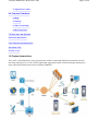
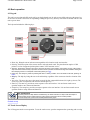
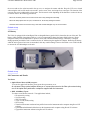
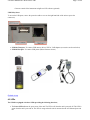
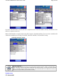
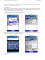
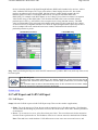
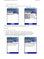
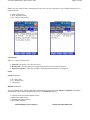
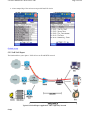
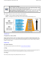
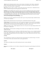
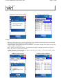
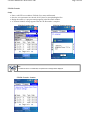
1
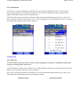
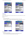
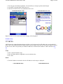
LX100 e-manual D07-00-019 Rev A00
LX100 e-Manual
Page 1 of 44
LX100 e-manual D07-00-019 Rev A00
Page 2 of 44
Please direct all questions to your local VeEX Sales Office, Representative or Distributor or contact VeEX technical
support at www.veexinc.com © Copyright 2007 VeEx Incorporated. All rights reserved.
No part of this user manual may be reproduced, translated into a foreign language or be transmitted electronically
without prior agreement and written consent of VeEX Incorporated as governed by International copyright laws.
Information contained in this manual is provided "as is" and is subject to change without notice. ™Trademarks of
VeEX Incorporated have been identified where applicable, however the absence of such identification does not
affect the legal status of any trademark.
Table of Contents
1.0 Product Introduction
2.0 About this User Manual
3.0 Safety Information
4.0 Basic Operation
4.1 Keypad
4.2 Touch Screen Display
4.3 Battery
4.4 Connectors and Panels
4.5 LEDs
5.0 Home Menu
5.1 IP Connection
5.2 Advanced IP
5.2.1 Ping Test
5.2.2 Trace Route
5.2.3 FTP Test
5.2.4 Web Test
5.2.5 ARP Wiz
5.3 Net Wiz
5.4 WiFi Wiz
5.5 VoIP
5.5.1 VoIP Expert
5.5.2 VoIP Call Expert
5.6 IPTV
LX100 e-manual D07-00-019 Rev A00
Page 3 of 44
5.7 Optical Power Meter
6.0 Common Functions
6.1 Help
6.2 Settings
6.3 Files (Test Results)
6.4 ReVeal software
7.0 Warranty and Software
8.0 Product Specification
9.0 Certification and Declarations
10.0 About VeEX
Go back to top
1.0 Product Introduction
The VePAL LX100 instrument is a next generation test solution to install and maintain IP and Optical networks
delivering triple play services. The LX100 is lightweight, rugged and weather resistant featuring an optical power
meter (option) and advanced IP test and verification capabilities.
LX100 e-manual D07-00-019 Rev A00
Page 4 of 44
Go back to top
2.0 About this User Manual
Every effort was made to ensure that the information contained in this user manual is accurate. Information is subject
to change without notice and we accept no responsibility for any errors or omissions. In case of discrepancy, the web
version takes precedence over any printed literature.
(c) Copyright 2006-2007 VeEX Inc. All rights reserved. VeEX, VePAL are registered trademarks of VeEX Inc and/or
its affiliates in the the USA and certain other countries. All trademarks or registered trademarks are the property of
their respective companies. No part of this document may be reproduced or transmitted electronically or otherwise
without written permission from VeEX Inc.
This device uses software either developed by VeEX Inc or licensed by VeEX Inc from third parties. The software is
confidential and proprietary of VeEX Inc. The software is protected by copyright and contains trade secrets of VeEX
Inc or VeEX's licensors. The purchaser of this device agrees that it has received a license solely to use the software as
embedded in the device, and the purchaser is prohibited from copying, reverse engineering, decompiling, or
disassembling the software.
This user manual is suitable for novice, intermediate, and experienced users and is intended to help you successfully use the
features and capabilities of the VePAL LX100 test set. It is assumed that you have basic computer experience and skills, and are
familiar with IP and telecommunication concepts, terminology, and safety.
For more technical resources, visit VeEX Inc web site at www.veexinc.com.
If you need assistance or have questions related to the use of this product, call or email our customer care department for
customer support. Before contacting our customer care department, you must have your product serial number and software
version ready. Please go to Basic Operations section for details on locating your unit serial number in the menus or locate the
serial number on the back of the chassis. Please provide this number when contacting VeEX customer service.
Customer Care:
Phone: + 1 408 970 9090
Email: [email protected]
Website: www.veexinc.com
Go back to top
3.0 Safety Information
Safety precautions should be observed during all phases of operation of this instrument. The instrument has been
designed to ensure safe operation however please observe all safety markings and instructions. Do not operate the
instrument in the presence of flammable gases or fumes or any other combustible environment. VeEX Inc. assumes no
liability for the customer's failure to comply with safety precautions and requirements.
Go back to top
LX100 e-manual D07-00-019 Rev A00
Page 5 of 44
4.0 Basic operation
4.1 Keypad
The unit is powered on and off from the red key on the keyboard area. In order to turn off the unit, press the power key
for at least 2 seconds. If the unit is not responding, holding the power key down by more than 10 seconds will force the
unit to power down.
The keyboard includes the following keys:
z
z
z
z
z
z
z
z
Home key. Bring the unit to its home menu regardless of its location on the user interface.
Print key. Performs a print of the current result or selected stored result. The print function requires a USB
printer. For a list of supported printer please contact VeEX customer service.
Store key. Performs the storage in the memory of the test set of the current results. If the result is running, it will provide a
snap shot at the moment the key is pressed. The store function provides an automatic storage with automatic naming and
time stamping function. To manipulate a stored file, please go to files.
History key. The history key resets any blinking LED due to a history condition. For more details on the LED, please go to
LEDs.
Help key. The help key brings the user to the online help, regardless of the current user interface location of the
unit.
Arrow key. The arrow key moves the cursor in any of the four supported directions (left, right, up, down). The
arrow key works in conjunction with the Enter and Escape keys.
Enter key. The enter key provides an enter sequence to the user interface. It is used in non touch screen
operation mode to enter menus and functions.
Escape key. The escape key provides an escape sequence to the user interface. It is used in non touch screen
operation mode to escape menus and functions.
Note: Standby Mode
By pressing Home and Help buttons simultaneoulsy, the tester switches to a sleep mode which helps to
preserve battery life and makes fast boot up time at the measurement site or location possible.
To exit the sleep mode, press Home and Help simultaneously again.
Go back to top
4.2 Touch Screen Display
The LCD supports touch screen operation. To use the touch screen, open the transparent door protecting and covering
LX100 e-manual D07-00-019 Rev A00
Page 6 of 44
the screen and use the stylus inserted in the top cover to navigate the menus and tabs. Keep the LCD cover closed
when using the unit in a non touch screen mode - use the arrow, enter, and escape keys to navigate. The location of the
cursor on the screen is indicated by a focus state. The focus state varies depending on the function or section of the test
set. Please observe the following precautions;
- Never use excessive pressure on the touch screen as this may damage its functionality
- Never use sharp objects such as a pen, screwdriver etc. as this may damage the surface
- Clean the surface of the touch screen using a soft cloth and mild detergent only. Do not use alcohol.
Go back to top
4.3 Battery
The VPAL is equipped with an intelligent Lilon rechargeable battery pack which is located in the rear of the unit. The
battery will be partially charged upon delivery, so it is recommended to charge the battery fully before use. Please
charge the battery at room temperature to preserve its life and to obtain maximum charge. The battery is charged
during operation provided the unit is connected to the AC Mains using the supplied AC adapter. Removing the battery,
while the unit is powered on is not recommended - this may result in damage. Remove the rubber cover on the left side
to connect the AC Main adapter to the unit.
Go back to top
4.4 Connectors and Panels
Test Ports:
z
Optical Power Meter (OPM) test port:
To access the optical test interface, please open the top connector cover.
An universal 2.5mm optical adaptor allows you to connect the test set to the fiber optic network using
one of the optical fiber patchcords or adaptors supplied with the instrument.
z
RJ45, 10/100Base-T port:
To connect to an Ethernet network - Test applications include;
{ IP connectivity testing
{ Net Wiz testing
{ WiFi Wiz testing
{ Voice over IP (VoIP) testing
{ IPTV testing
{ Transfer measurement results and test profiles between the instrument and a computer using Reveal LX
software
{ Upload/download channel tables between the instrument and a computer using Reveal LX software
{ Upgrade the instrument software using Reveal LX software
LX100 e-manual D07-00-019 Rev A00
{
Page 7 of 44
Remote control of the instrument using Reveal LX software (optional)
USB Utility Ports:
To access the USB ports, remove the protective rubber cover on the right hand side of the unit to expose the
connectors;
z
z
USB 2.0 Client port: To connect USB memory drives, WiFi or VoIP adaptors (accessories are shown below)
USB 2.0 Host port: To connect USB printer (future firmware release)
Go back to top
4.5 LEDs
The LX100 is equipped with three LEDs providing the following functions;
z
The Power LED indicates the power state of the unit. The LED is off when the unit is powered off. The LED is
green when the unit is powered on. The LED is orange when the unit is connected to the AC Main and powered
off.
LX100 e-manual D07-00-019 Rev A00
z
z
Page 8 of 44
The IP LED is linked to the IP connection function. The LED is solid red when there is no IP connection or
green when a valid IP connection is established.
The WiFi LED indicates a successful WiFi connection.
Note: The LED history function and LED reset function key on the rubber keyboard (O -> O) serves no function on
the LX100.
Go back to top
5.0 Home Menu
This menu can be reached at anytime during operation by pressing the home key, accessible on the rubber keyboard.
LX100A Home Menu
The upper part of the menu (IP connection, Advanced IP, Net Wiz, WiFi Wiz, VoIP, IPTV and Optical Power Meter)
consists of applications specific to the test set, while the lower part of the menu contains applications (Help, Settings,
Files) which are common to all VeEX VePAL handheld test sets.
Some test capabilities may be specific to a certain product while other features may require the purchase of a software
option in order to be displayed or be enabled.
Go back to top
5.1 IP Connection
Enter a Static IP address or use DHCP to connect to the network. If DHCP is selected, an IP address will be
automatically assigned to the test set. The user can also turn the DNS server option On of Off.
LX100A DHCP IP setup
LX100A Static IP setup
LX100 e-manual D07-00-019 Rev A00
Page 9 of 44
If a Static connection mode is selected, the user is required to enter a Local IP, Subnet, Gateway, and DNS IP (if the
DNS server option is turned on)
Note: A DNS IP address is required when using URL format as a destination address. The user needs to establish an IP
connection and address prior to Ping, Trace Route, Web/FTP, ARP Wiz, VoIP, and IPTV testing.
LX100A IP connection - Result
Note: IP Connection
Ensure the Status is PASS and the IP icon is green before continuing with any IP tests. If the status fails, go
back to the setup screen to verify that the parameters are entered correctly - also ensure that the ethernet
cable is connected properly before trying to reconnect. Check the status LED on the Ethernet connector (on
the side of the unit) to look for port and network activity.
Go back to top
5.2 Advanced IP
LX100 e-manual D07-00-019 Rev A00
Page 10 of 44
An IP test will verify that the IP network is configured properly and connected to the Internet. Depending on the IP
options purchased, the following tests are possible;
5.2.1 Ping Test
PING is a popular computer network tool used to test whether a particular host is reachable across an IP
network. A Ping is performed by sending an “echo request” or ICMP (Internet Control Message Protocol) to
the target host and listening for “echo response” replies.
The destination address can be in IP address or URL format.
LX100A Ping
Test address setup
LX100A Ping
Test setup
The Ping Result indicates the number of Pings Sent and Received. Unreachable and Missing Pongs are also recorded.
PING also estimates the round-trip time, in milliseconds.
LX100A Ping
Go back to top
address edit
LX100A Ping Result
LX100 e-manual D07-00-019 Rev A00
Page 11 of 44
5.2.2 Trace Route
Trace Route is a common method used to find the route to the destination IP address or URL. It is often used to
identify routing problems and unreachable destinations. All the remote IP addresses and their reponse times are
displayed indicating possible network congestion points.
Select Trace Route to proceed with Trace Route test. Enter the desired destination and press ‘Trace’ to start. Trace
Route results provide all the hops with Time To Live (TTL) and addresses up to the destination. If there is no response
from a particular hop then an asterix will be displayed.
LX100A Trace Route
setup
LX100A Trace Route result
Go back to top
5.2.3 FTP Test
The File Transfer Protocol is used to verify the actual throughput of upstream or downstream data rate by
sending or receiving files of known size.
For FTP download or upload, the user needs to enter a valid IP Address, File/Path, User name and Password. For FTP
upload, the user can also set the file size to be transmitted.
Press ‘Start’ to initiate the download or upload process. The FTP download or upload results provide a Pass or Fail
status and detailed information specific to the download or upload.
LX100A FTP upload
LX100A FTP download
LX100 e-manual D07-00-019 Rev A00
Page 12 of 44
Go back to top
5.2.4 Web Test
Web Test is used to verify that the internet is properly provisioned at the service point. Web Mode can be set to either
Web Test or Web Browser.
Web Test:
z
z
z
Select Test from Web Mode
Enter or select the desired IP address or URL destination, the repetition time, then press ‘Start.’
The result is a simple Pass / Fail indication and basic information pertaining to the throughput and transfer rate.
LX100A Web Test
setup
LX100A Web Test result
Web Browser:
z
z
z
Select Browser from Web Mode
Enter or select the desired IP address or URL destination, and encoding, andthen press ‘Start.’
The screen will turn blank while launching the spider web browser engine.
LX100 e-manual D07-00-019 Rev A00
z
z
z
Page 13 of 44
The web page is divided into quadrants. Use the slide keys to navigate up/down and left/right.
It is possible to navigate links within the screen.
Click the close button in the Top right hand corner to exit.
LX100A Web Browser setup
LX100A Web Browser result
Note: If a DNS server is not detected, an error message will be displayed.
Go back to top
5.2.5 ARP Wiz
ARP Wiz uses the Address Resolution Protocol (ARP) to verify the status of each IP address in a user selectable IP
range. ARP is the standard method for finding a host's hardware address when only its network layer address is known.
In other words, ARP is used primarily to translate IP addresses to Ethernet MAC addresses. ARP is defined in RFC
826
Setup:
z
z
z
Enter a desired IP address range
Enter the Subnet address (if applicable) or use the default value.
Press ‘Start’
Result:
z
The MAC addresses associated with active IP addresses in the range are displayed.
LX100A ARP Wiz Setup
LX100A ARP Wiz Result
LX100 e-manual D07-00-019 Rev A00
Page 14 of 44
Note: ARP
The ARP protocol by definition can only work within the same subnet as the IP address provided to the test
set in IP Status.
Go back to top
5.3 Net Wiz
The Net Wiz function allows you to test the ethernet cable and associated network environment. A typical application
is shown below;
LX100 e-manual D07-00-019 Rev A00
Page 15 of 44
Typical Net Wiz Application
Test functionalities include;
z
z
z
z
z
Cable Analysis with distance
{ to switch with MDI mode (Straight or Crossover)
{ to fault, type of fault (Open, Short, Impedance Mismatch)
Analyze the network and automatically report
{ Stations
{ Routers/Gateway
{ Printers
Provide MAC and IP addresses of each device
PING each device and verify the device is active
Provide detected networks (NetBiOS, IPX, etc)
Status
z
z
z
Press ‘Start’ to begin the test.
The test set will report the connection type (Straight or Cross Over) if connected to an end point device.
If a fault is detected (Open or Short), the fault will be indicated including the distance to the fault.
Discovery
z
z
Before proceeding with the discovery function, please go to IP Tools to establish a connection.
Enter the desired IP address range and press ‘Start’
LX100 e-manual D07-00-019 Rev A00
LX100A Net Wiz setup
Page 16 of 44
LX100A Net Wiz Discovery setup
Discovery Result:
z
Summary tab reports;
{ Total transmitted and received frames
{ Received frames in error
{ Speed advertized
{ Duplex mode advertised
{ Number of devices and networks found
LX100A Net Wiz Discovery Summary
LX100A Net Wiz Discovery Devices
Discovery Result:
z
Devices tab indicates;
{ Total number of devices found
{ Number of devices i.e. routers, servers or hosts.
{ Attribute of each device discovered including Ping test result.
LX100A Net Wiz Discovery Devices contd.
LX100A Net Wiz Discovery Networks
LX100 e-manual D07-00-019 Rev A00
Page 17 of 44
Discovery Result:
z
Networks tab indicates;
{ Number of IP Subnets, Hosts, Domain, and Named Hosts Found.
Go back to top
5.4 WiFi Wiz
The function allows you to test wireless WiFi 802.11b and 802.11g networks. A typical application is shown below.
LX100 e-manual D07-00-019 Rev A00
Page 18 of 44
Typical WiFi Wiz Application
The WiFi Wiz function supports;
z
z
z
z
z
z
WEP Encryption
Scanning
SSID broadcasting and report
Signal Strength
Mode (AP, IF) and Security
IP Connection and Ping Test
Setup:
z
z
z
z
Plug the WiFi adaptor into the USB port. Allow at least 30-45 seconds for the unit to detect the wireless adaptor
and for the software driver to load.
VPAL products support Linksys USB wireless adaptors only and have the necessary software driver built into
the Linux operational system. Do not use other wireless adaptors as this may damage the unit.
Tap on the pull down menu to turn the wireless USB adapter on. An information box will display the initiation
process of the USB and this process will take about 90 seconds.
Ensure the USB wireless adapter is connected before turning it on.
WiFi Adaptor
LX100A WiFi setup - Activation
Scan - Tap on the Scan tab once the test set has detected the wireless USB adapter. Press Scan on the bottom to start
scanning the site. When scan is completed, the test set will show the number of SSIDs, Channels, and the number of
SSiDs in Infrastructures mode and Ad-Hoc mode.
SSiD - Tap on the SSiD tab after the scan is completed. Select one of the SSiDs to start a connection. If the SSiD is
locked, a network key is required to complete the connection. The WiFi function supports WEP encryption. The key
can either be 10 characters or 26 characters. Note: If the user entered the wrong network key the test set will still
connect to the Access Point, however, it will not be able to connect to the web or to perform the Ping test.
Note: Select the manual selection to enter the parameters manually if the SSiD did not detect the AP that the user is
searching for.
LX100A WiFi Scan
LX100A WiFi SSID
LX100 e-manual D07-00-019 Rev A00
Page 19 of 44
Connection
Once connected, the connection screen will display the following information on the connection;
z
z
z
z
z
z
z
SSiD
BSSiD MAC address
Channel number
Encryption type - WEP, WPA, Disabled
Type - Adhoc, Infrastructure
Signal strength is constantly updated so the value varies.
Link Quality is constantly updated so the value varies.
Note: Signal versus Link Quality
Link quality - Fundamentally, the best way to measure link quality is to derive the Signal to Noise Ratio
(SNR) of the desired received signal. For that to happen, a demodulator in the receive chain needs to
provide information about the confidence of the detected symbol - also known as soft detection. However,
with modern CMOS transceivers used in WiFi type products, soft detection is not provided. Instead, in a
typical application, there are two measures of the Rx signal quality: Received Signal Strength Indication
(RSSI) and integrity check of the demodulated data by either Cyclic Redundancy Check (CRC) or PN
code correlation strength.
Signal quality - The RSSI can be used as a measure of signal quality when there is no interference. But,
in the case where the receiver experiences interference, the RSSI may falsely indicate sufficient signal
strength even if the desired signal is completely jammed by the interfering signal. This is because the
RSSI cannot distinguish the desired signal from the interfering signal. In this situation, a data integrity
check can be used to detect if the demodulated data is corrupted, and then subsequently adjust the transmit
power. Using a CRC check as a measure of link quality implies that a few bit errors occur in the data or
voice transmission before the transmit power can be increased. There is a lot of controversy about the term
signal quality used in WLAN networks but the most likely definition of “signal quality,” or “PN code
correlation strength” is that it is some metric of the correlation between the correct symbol-stream and the
actual symbol-stream received. For example, the PHY might count the average number of “wrong” bit
positions over a window of some number of symbols, where zero “wrong” bit positions equals 100%
signal quality and more “wrong” bit positions results in lower signal quality.
Signal strength and RSSI - In reality, there are four units of measurements used to represent RF Signal
Strength namely mW( milliwatts), dBm (“dB”-milliwatts), RSSI (Received Signal Strength Indicator), and
a percentage measurement. Signal strength defined in the IEEE 802.11 recommendation for WiFi type
LX100 e-manual D07-00-019 Rev A00
Page 20 of 44
devices is based on the Received Signal Strength Indicator (RSSI) and is intended to be used as a ‘relative
value’ within the WiFi chipset. The 1-byte value can have values ranging from 0 to 255, but vendors
prefer to use arbitrary scales from 0 to RSSI_Max but in fact no vendor actually measures the 256
different signal level values so each adopts and uses their own specific maximum RSSI value
(RSSI_Max). For example on the WiFi adaptor we use, Linksys (Cisco) chooses to measure 101 separate
values for RF energy so their RSSI_Max is 100. Note that the RSSI value is not associated with any
particular power scale (e.g. mW) and it is also not required to be of any particular accuracy. The RSSI
value is used internally by the microcode in the adapter and by the device driver and this is why vendors
are not forced to use a compatible standard. As a result, the signal strength numbers reported by an 802.11
device or adaptor will not be consistent between two vendors, and should not be assumed to be
particularly accurate or precise.
LX100A WiFi Connection
LX100A WiFi Ping
Ping - Before performing the Ping test, ensure the WiFi connection is Up and the WiFi icon (on the top of the screen)
has turned green.
Note: WiFi Ping Test
The signal level might change depending on the distance between the Access Point and the test set
causing the WiFi connection to drop. Furthermore, if the link quality is below 60%, the connection might
drop too.
If the connection drops the test set will automatically search for the connection and re-connect. Always
ensure the connection is active before performing the Ping test.
Go back to top
5.5 VoIP Expert and VoIP Call Expert
5.5.1 VoIP Expert
Setup: Select the VoIP tab to proceed with VoIP Expert setup. There are three modes or applications;
z
z
Client - Tou se the test set as a Client, the user needs to input the Server’s IP address and set a Test Duration.
The File Name and Encoding are preset in the test set for the current release. Press ‘Start’ when the parameters
are all entered
Server - To use test set as a server, select Server then press ‘Start.’ The test set then waits for the connection
from the Client to perform the test. The IP address of the server is the one entered or obtained in the IP Status
Note: Client and Server mode simulate a VoIP call between two test sets or one test set and a server, and
LX100 e-manual D07-00-019 Rev A00
Page 21 of 44
measure the VoIP quality parameters.
z
IP Phone - For IP Phone or VoIP Call Expert mode, go to VoIP - IP Phone Section
LX100A VoIP Expert server setup
LX100A VoIP Expert client setup
For Client mode, the user needs to input the Server’s IP and Test Duration. The File Name and Encoding are preset in
the test set for the current release. Press ‘Start’ when the parameters are all entered.
Server Status
There are 4 stages in Server test mode:
z
z
z
z
z
Wait for Client or Server - Wait for the Client to connect with the server or vice versa
Connecting - Once client is connected to the server, the downstream test will be performed.
Downstream - As soon as the downstream is completed the upstream test will be performed.
Upstream - As soon as the upstream is completed, a Pass or Fail result will be indicated
File Pass - File Pass will be displayed when the test is completed.
LX100A VoIP Expert connection status
LX100A VoIP Expert downstream status
LX100 e-manual D07-00-019 Rev A00
Page 22 of 44
Note: Loss, Dup, and DV can be generated at any time, however, these functions are only available when the test set
transmits the file.
z
z
z
LOSS - Packet Loss
DUP - Duplicate Packet
DV - Delay Variation (DV)
LX100A VoIP Expert upstream status
LX100A VoIP Expert result
Client Status:
There are 3 stages in Client mode:
z
z
z
Upstream - Stream the voice file to the Server.
Downstream - Once the upstream is completed the downstream test will be performed.
VOIP Test Complete - VOIP Test Complete will be displayed when the test is completed.
Status:
Status tab indicates;
z
z
z
ST - Start Time
ET - Elapsed Time
Test progress
MOS/R tab indicates;
The Mean Opinion Score (MOS) and R-factor measurements performed by the Telchemy™ VQmon® VoIP quality
measurement engine which is integrated into the test set. VQmon/SA supports;
z
z
z
z
Listening and conversational quality metrics
MOS scores and R factors
Detailed packet/RTP statistics
Jitter buffer emulation
LX100A VoIP Expert Test completed
LX100A VoIP Expert MOS status
LX100 e-manual D07-00-019 Rev A00
Note: Call
Page 23 of 44
Quality
Listening Quality (LQ) - Refers to how the users rate what they “hear” during a call
Conversational Quality (CQ) - Refers to how the users rate the overall quality of a call based on
the listening quality and their ability to converse during a call. This includes any echo or delay
related difficulties that may affect the conversation
Transmission Quality - Refers to the quality of the network connection used to carry the voice
signal.
Packets tab indicates;
z
z
z
z
z
Analysis on packet loss
Duplicated packets
Out of sequence packets
Packet rate
Packet jitter
Events tab indicates;
LX100 e-manual D07-00-019 Rev A00
z
Page 24 of 44
A time stamped log of the various test steps with Pass/Fail criteria
LX100A VoIP Expert Packet status
LX100A VoIP Expert Events
Go back to top
5.5.2 VoIP Call Expert
The function allows you to place a VoIP call over an IP and PSTN network.
Typical VoIP Call Expert Application - DSL Triple Play Network
Setup:
LX100 e-manual D07-00-019 Rev A00
Page 25 of 44
Select the VoIP tab to proceed with the IP Phone setup.
z
z
z
z
z
z
z
Profile - Recall an existing or save a new profile
Mode - Select IP Phone from the Mode pull down menu.
Protocol - SIP and H.323 are the only protocols supported at this time.
Registration - Direct or Peer to Peer.
User name and Password - for registering with the call authentication server
Codec - select between G.711A, G.711U, G.728 or G.729
Headphone - When the user turns on the headphone selction, an information box appears prompting you to
plug-in the VeEX USB headphone adaptor. Ensure the headphone USB adapter is properly connected to the test
set before pressing ‘OK’
LX100A VoIP Call Expert Setup
LX100A VoIP Call Expert - USB message
Registration Status
z
z
z
The status will show the registration progress and call activity if any
Once the test set has completed the registration, the test set status will change to Online.
If the test set fails to register, repaeat the setup process and ensure all the parameters are entered correctly and
register again.
LX100A VoIP Call Expert registration
LX100A VoIP Call Expert setup
LX100 e-manual D07-00-019 Rev A00
Page 26 of 44
Call Status:
To place a call;
z
z
z
First enter a destination IP address - The address can be a phone number (phone number@sipserver) or an alias
(bob@sipserver)
Press ‘Call’ - The status will show the call progress e.g. ‘Dialing in progress’
The status changes to ‘Call connected’ when the destination end point answers the call
LX100A VoIP Call Expert dialing
LX100A VoIP Call Expert connected
Receive Call Status:
z
z
z
An information box appears on screen when there is an incoming call
The user can choose to accept or to decline the call
Once connected, you can use the USB headphone adapter to talk and listen
LX100A VoIP Call Expert - Incoming call
LX100 e-manual D07-00-019 Rev A00
Go back to top
5.6 IPTV
The function allows you to perform IPTV testing in a Triple Play network. The feature supports;
z
z
z
z
z
Set Top Box (STB) emulation
IGMP/RTSP signaling, MPEG2/4, H.264 encoding, RTP/VC1/MPEG-TS transport streams
Packet Statistics: packet loss, jitter, delay, PID mapping
Video/Audio stream rates
Channel zapping for quick and complete installation check
Page 27 of 44
LX100 e-manual D07-00-019 Rev A00
Page 28 of 44
Typical IPTV Test Application - DSL Triple Play Network
The IPTV menu allows you to configure the following parameters;
Setup tab:
z
z
Channel Table - Select the IPTV channel table to test. The IPTV channel table can be configured manually on
the test set using the Editor function. Alternatively, the IPTV channel table can be created using the Reveal LX
software which can subsequently be downloaded onto the test set.
Channel # - Select and configure the channel to be analyzed. Up to three channels or streams (Multicast or
Unicast) can be analyzed simultaneously. The channel can be in IP address or URL format.
Probe tab:
z
z
Channel Name
Channel Address
Editor tab: Allows you to edit;
z
z
IPTV channel name
IP address associated with the IPTV channel
IPTV Channel Setup
IPTV Channel Probe
Results:
IPTV Summary tab displays;
z
z
z
z
z
Status should indicate Streaming
Line rate is the Ethernet line rate
Total stream - packets associated with the video and audio content of the MPEG-2 Transport Stream (TS)
Video stream - packets associated with the video content
Audio stream - packets associated with the audio content
Note: IPTV Stream Analysis
Up to three streams can be analyzed and the bandwidth associated with the whole TS is displayed. Video
streams typically consume more bandwidth than audio streams, which in turn use more bandwidth than
data streams. In this manual, MPEG-2 refers to the video transport stream defined in IEC13818 standard
LX100 e-manual D07-00-019 Rev A00
Page 29 of 44
and not any compression technology used in the payload or transport packet. The MPEG-2 Transport
stream contains seven packets of 188bytes each which transports either the MPEG-2, MPEG-4 or VC-1
encoded video.
IPTV Stream Summary
IPTV Results - Video Stream
IPTV Result Video (Page #1) displays the following results;
z
z
Packet Rx - is the (total number of packets received) - Packet loss (total number of packets lost)
Packet loss - measured by analyzing video packet flows and determining the presence of a continuity error
event. Because each video packet carries a sequence number, continuity errors can be determined easily.
Missing, OOS and duplicate packets are counted as errors. Packet loss is typically seen on all channels arriving
at the customer, because they are not source or content related problems. Analysis of the DSL or Ethernet
physical layer normally determines the problem area. Packet loss impacts video quality and leads to highly
visible errors. When lost packets contain I-frames, the impact will be more pronounced because the STB has to
wait for the next Iframe to “reset” itself. H.264 encoding which uses a longer Group of Pictures (GOP) structure
aggravates problems because higher compression contains more information. Consequently, the loss of a single
H.264 frame will likely have a greater impact on picture quality.
Note: IPTV Network Performance
Due to the real-time nature of IPTV, MPEG-2 is transported over UDP (IPv4/UDP), hence retransmission or
re-ordering of packets is not intended. Video quality is largely determined by network performance
parameters including Packet loss, Packet jitter and IGMP latency.
IPTV Results - Video Stream Rates
IPTV Results - Video Packet Jitter
LX100 e-manual D07-00-019 Rev A00
Page 30 of 44
IPTV Result Video (Page #2) - displays the Stream Rate results;
z
Table provides individual bit rate statistics for each stream;
{ Total is the total number of bytes related to the Video, Audio and Data payloads
{ Video is the number of packets classified as video packets
{ Audio is the number of packets classified as audio packets
{ Data is the number of packets classified as data packets
{ Other is the number of packets classified as unknown packets
IPTV Result Video (Page #3) - displays the Packet Jitter results;
z
z
z
Packet Jitter displayed in milliseconds.
Current is the current jitter value
Max is the maximum jitter value
Note: Packet Jitter
This measurement is based on the data packet inter-arrival time which is a measure of packet arrival
variance. Packet jitter affects packet arrival throughout the network. Variations lead to buffer under /
overflows at the receiving equipment e.g. STB. Jitter impacts the way packets are handled at various net
work elements i.e. If the jitter is too high, packet loss will increase as queuing software tries to load balance
traffic at network elements. Packet jitter should not be confused with PCR jitter (described below). When
Packet jitter is present, the cause is normally related to the Ethernet physical layer. When PCR jitter is
present, then the cause is most likely related to the program flow and could be related to an encoder not
performing to specification.
IPTV Results - Video QOS
IPTV Results - Video Transport
LX100 e-manual D07-00-019 Rev A00
Page 31 of 44
IPTV Result Video (Page #4) - displays the Quality of Service (QOS) results;
z
z
z
z
PCR Clock - Presence of 27MHz Program Clock Reference
PCR Jitter - PCR deviation in (ms)
MPEG Packet Loss - continuity error (%)
Latency - the time to complete a program change measured in milliseconds (ms)
Note: Program Clock Reference (PCR)
MPEG TS normally contain a built-in timing packet known as the Program Clock Reference (PCR).
Recovering the 27 MHz clock at the decoder end of the transmission system is necessary to re-create the
video signal. The PCR values need to be correct at the signal origin and should not be distorted along the
transmission path to a point where decoding the compressed signal becomes problematic. Measuring the
interval between the arrival of PCR values, the accuracy of the expected values and also the jitter
accumulated on those PCR values transmitted is necessary to assure that streams can be decoded. PCR
jitter is a good indication of timing distortions due to poor encoding. Excessive PCR jitter results in visual
impairments such as frame freezes, color loss and pixelization. The amount of PCR jitter that is considered
excessive varies, and depends on various factors including STB buffer sizes and software architecture.
However, in today’s packetized video networks, PCR jitter should not exceed 10 ms. If PCR jitter is not
constant, then a momentary problem from inserting local programming may be the cause.
IPTV Result Video (Page #5) - displays the Transport results;
z
z
MPEG Packet Loss
Packets expected
IPTV Results - Video MDI
IPTV Results - Video MAP
LX100 e-manual D07-00-019 Rev A00
Page 32 of 44
IPTV Result Video (Page #6) - displays the Media Delivery Index (MDI) results;
z
z
z
MDI (Media Delivery Index) - value in a ratio
DF (Delay Factor) - Average, Minimum and Maximum values. Also defined as cumulative IP jitter, it
represents the time it would take to drain an output buffer and
ensure good video playback.
MLR (Media Loss Rate) - Average, Minimum and Maximum values. Alos defined as the packet loss rate due
to dropped packets, bad/corrupted packets, or out-of-sequence packets.
Note: Media Delivery Index (MDI)
Defined by RFC4445 is the only standardized video quality metric available today. MDI quantifies two IP
transport impairments, namely Packet Jitter or Delay and Packet Loss. These test parameters are defined
as Media Delay Factor (MDI-DF) and Media Loss Rate (MDI-MLR). The Delay Factor (DF) indicates how
long a data stream must be buffered at its nominal bit rate to prevent packet loss. It gives a general idea of
network jitter using the DF measurement. The MDI-DF can give a measure of congestion in a network, by
showing utilization level, and detect if queuing is happening in network components, but it does not indicate
how much of this is due to video packet bunching. The Media Loss Rate (MLR) is the number of packets
lost during a 1 second period. MDI is expressed as a ratio namely; Delay Factor : Media Loss Rate, e.g.
70:15 The above ratio shows a delay factor of 70ms and 15 packets lost per second. MDI and MPEG
packet loss together provides a good indication of IP transmission and non related IP issues.
IPTV Result MAP:
The MAP table provides a summary of the stream composition and the programming present.
z
z
z
z
Str - Indicates stream number
PID - Packet Identifier is a unique channel address identifier. PID enables identification and reconstruction of
the programme and is used in conjunction with the Programme Service Identifier (PSI) packets. The decoder
uses the PID and PSI to identify the Programme Association tables (PAT). PAT contain Program Map tables
(PMT) that point the decoder to the packets associated with the channel or programme such as video, audio and
data content in the transport stream.
Type: Payload description
Description: PID description on a per stream basis
Note: MPEG-2 Transport Stream (TS)
A Packetized elementary stream (PES) is a continuous traffic stream of 188-byte packets carrying the
digital signal. Since single/multiple programs can be carried per stream, a reference point from which the
STB can synchronize and start the actual decoding from, must be provided. Each 188-byte packet consists
of a 4-byte header containing this reference point which is a PAT table and a PID value equal to 0. The
Packet Identifier (PID) contained within the 4-byte header, is a unique channel address identifier allowing
LX100 e-manual D07-00-019 Rev A00
Page 33 of 44
identification and reconstruction of the program. The PID is used in conjunction with the Program Service
Identifier (PSI) to identify Program Association Tables (PAT) which in turn hold Program Map Tables (PMT).
The PAT table is also the table containing all program information ensuring the consumer receives updated
program changes. The PAT table lists all the programs in the transport stream and associates each
program with another PID, that holds a program map table (PMT) as its payload. PMT lists the Video, audio
and eventual encryption information. The Payload Structure Identifier (PSI) table needs to be consistent
with the PID table. PAT and PMT are inserted into the stream so that the decoder performs correctly. These
two items should always be present.
IPTV Channel Scan
IPTV Channel Viewer
IPTV Scan - displays the Scan results;
z
z
z
z
Channel - Channel number (IP address:UDP port) being scanned
Zap time (ms) - Also known as inter-channel change delay. Time between a channel leave request is sent and
the receipt of the first byte of data from the new multicast channel. It is the IGMP Join Latency + Channel
Switch Delay (STB dependent). Channel zapping should be < 700ms.
Status - OK, no packet, Fail
Bandwidth - bandwith associated with the stream
IPTV Zapping Overview
LX100 e-manual D07-00-019 Rev A00
Page 34 of 44
Note: IGMP and Channel Zapping
IGMP is a signaling protocol that enables each STB to obtain only the programming that the viewer is
interested in watching, thus conserving bandwidth in the access network. STB's use the IGMP to change
channels, by leaving and joining multicast groups representing channels.
Key to IPTV QoE, is how fast and reliably end users can change TV channels, also known as "channel
zapping". Essentially it is calculated as the time taken between sending a channel leave request and
receiving the first video data of the new video stream.
Refer to DSL Forum TR-126 Triple Play Quality of Experience (QoE) requirements for more info.
IPTV Viewer - displays the Picture and is useful as a channel identifier.
z
z
Channel - Unicast or Multicast including IP address and UDP port #
Status – Decoding please wait. Please allow 20-30 seconds for buffering and decoding to occur.
Physical Layer and Protocol Stack Troubleshooting Concept
Go back to top
5.7 Optical Power Meter (OPM)
With its optional Optical Power Meter, the LX100 is an ideal tool to troubleshoot FTTH and PON Networks. The
standard power meter can be used to verify the physical layer (optical power level) while the Advanced PON Power
Meter functions allows in-service measurement of bi-directional signals between OLT and ONT using an industry
standard 2x2 optical coupler.
Go back to top
6.0 Common Functions
The following common functions are described in the Common Functions E-Manual
6.1 Help
Help provides a text based online help related to the operation of the test set and the measurements performed. The
user can directly access from the table of contents hyperlinks or by doing a search on keywords.
6.2 Settings
This section provides settings for the global parameters of the test set.
LX100 e-manual D07-00-019 Rev A00
Page 35 of 44
About: Provides information about the software version, hardware serial number, MAC addresses, and installed
options. This section also allows the user to add software options by programming the new option with the key
provided by VeEX Inc Customer Care Department.
Bluetooth: Provide the utilities to configure, enable, and associate devices with the test set via Bluetooth wireless
interface. The Bluetooth option needs to be purchased to enable this menu.
Backlight: Provides backlight control of the unit. The user can select the brightness for battery and AC operations.
The user can also select a timer to turn off the backlight if the device is not used. This function helps improve the
battery life. There are two settings, one for battery power and one for AC power. To enable the timer, check the item
"Turn off backlight if device is not used for" and with the pull down menu adjust the duration of the idle time before
the backlight is turned off. Once the timer is active, and the backlight turned off, any action on the test set (touch
screen, keyboard) will turn on the backlight again.
Please refer to the backlight section, go to Backlight section.
Screen: Go to this section to change the screen theme, blue or green. Also provides the utility to calibrate the touch
screen when out of calibration.
Power: Provides information about current powering source, and information about the battery gauge.
Global Settings: This section allows the user to select an alternative language for the user interface (only English is
supported at this time) and also to set the unit system (English - feet or Metric - meter). It also provides selection for
File Name Prefix. Once entered the prefix will be added to any file exported out of the test set.
Selftest: This utility provides a complete diagnostic of the test set. The report can be exported and provided to VeEX
Inc Customer Care Department.
Date and Time: Set the date and time accordingly to the customer time zone. Daylight savings are automatically
enabled in the utility.
Network: Set the parameters for the 10/100T port available on the chassis. The port, once set is automatic and always
tries to connect with the settings once connected to a proper network. These settings are active when the port is not
used for testing. The applications that will use these settings are remote control, and connection to ReVeal, VeEX PC
software application.
6.3 Files
The test instrument saves the Files (Test results) in the unit's internal memory for recall and viewing. To access the
saved results, click Files on the main menu. There are three application tabs;
Capacity
The capacity screen displays the current file capacity and current % memory utilization.
Explorer
The Explorer screen allows you to View, Delete, or Rename files. File protection is provided using the Lock/Unlock
button.
File Capacity
File Explorer
LX100 e-manual D07-00-019 Rev A00
Page 36 of 44
Note: The test results files are stored in a proprietary format. If you need to archive, print or generate test reports,
please export the files using one of the following methods.
z
z
z
USB Memory Device via USB interface. For more information, click here.
FTP server Upload or Transfer via the unit's Ethernet interface. For more information, click here.
File transfer using Reveal software via the unit's Ethernet interface. For more information, click here.
After the results are exported, please use ReVeal software to manage and process the files.
USB File Transfer
Setup - Tap the Transfer Mode pull down menu to select USB as the transfer method.
USB File Transfer setup
USB Warning
Note:
Ensure an USB Storage device is connected properly to the test set before selecting the USB transfer
LX100 e-manual D07-00-019 Rev A00
Page 37 of 44
mode.
USB memory stick detection message
USB File Transfer setup
Transfer:
z
z
z
z
z
When the USB transfer mode is selected, USB storage device (memory stick) detection starts. An information
box appears providing information on the detection process.
Input a File/Path once the USB storage device is detected - A File/Path is the name of the folder where the files
will be stored on the USB device.
Press ‘Transfer’ to start the file transfer - An information box appears indicating the transfer is in progress.
Press ‘OK’ to exit or to abort the file transfer.
During the transfer, a % progress message appears in the file transfer window. A "Transfer finished" message
appears when the transfer is complete.
USB File Transfer progress
USB File Transfer completed
LX100 e-manual D07-00-019 Rev A00
Page 38 of 44
FTP File Transfer
Setup:
z
z
z
z
Enter a valid FTP server address, File/Path, User name, and Password.
Once the server parameters are entered, click ‘Upload’ to start uploading the files.
During the transfer, a % progress message appears in the file transfer window.
A "Transfer finished" message appears after the FTP file transfer is complete.
FTP File Transfer setup
FTP File Transfer progress
Note:
If a valid FTP server is not detected, an Upload error message will be displayed.
FTP File Transfer - Caution
LX100 e-manual D07-00-019 Rev A00
Page 39 of 44
Go back to top
6.4 Reveal software
Please install the ReVeal LX software (supplied with the instrument) onto your PC. The ReVeal software allows you
to;
z
z
Manage and process test results
Remote Control the instrument
Managing and processing Files (test results)
z
z
Launch ReVeal LX software on your PC to open and process the exported files.
The test instrument does not need to be connected to the PC when processing results.
The Results application allows you to Download and Manage Test results.
The Results menu allows you to;
z
z
z
z
z
z
Download Results
Manage Results
Create Reports
Convert Results to PDF format
Convert Results to CSV format
Print Results
For detailed information, refer to the ReVeal LX user manual.
LX100 e-manual D07-00-019 Rev A00
Go back to top
Remote Control:
z
z
z
Launch ReVeal LX software on your PC to remote control the instrument.
The test instrument must be connected to the PC via an IP connection.
Select the remote control application which is located in the Tools menu.
For detailed information, refer to the ReVeal LX user manual.
Page 40 of 44
LX100 e-manual D07-00-019 Rev A00
Page 41 of 44
Go back to top
7.0 Warranty and Software
Warranty Period: The warranty period for hardware, software and firmware are three (3) years from the date of shipment to the
customer. The warranty period for battery pack, LCD, LCD touch panel, LCD protective cover, and accessories (including but not
limited to patch cords, AC adaptor, SFP, USB adaptors, carrying case, carrying pouch) is limited to one (1) year.
Hardware Coverage: VeEX Inc warrants hardware products against defects in materials and workmanship. During the warranty
period, VeEX will, at its sole discretion, either
z
z
Repair the products
Replace the hardware which prove to be defective
provided that the products that the customer elects to replace is returned to VeEX Inc by the customer along with proof
of purchase within thirty (30) days of the request by the customer, freight prepaid.
Software Coverage: VeEX Inc warrants software and firmware materials against defects in materials and workmanship. During
the warranty period, VeEX will, at its sole discretion, either
z
z
Repair the products
Replace the software and/or firmware which prove to be defective
provided that the products that the customer elects to replace is returned to VeEX Inc by the customer along with proof
of purchase within thirty (30) days of the request by the customer, freight prepaid.
Additionally, during the warranty period, VeEX Inc will provide, without charge to the customer, all fixes, patches and
enhancements to the purchased software, firmware and software options. VeEX Inc does not warrant that all software
or firmware defects will be corrected. New enhancements attached to a software option require the option to be
LX100 e-manual D07-00-019 Rev A00
Page 42 of 44
purchased (at the time of order or the time of upgrade) in order to benefit from such enhancements.
Limitations: The warranty is only for the benefit of the customer and not for the benefit of any subsequent purchaser or licensee
of any merchandise (hardware, software, firmware and/or accessories)
Revoking the warranty: VeEX Inc does not guaranty or warrant that the operation of the hardware, software or firmware will be
uninterrupted or error-free. The warranty will not apply in any of the following cases:
z
z
z
z
z
Improper or inadequate maintenance by the customer
Damage due to software installed by the customer on the unit without prior authorization (written) from VeEX
Inc.
Unauthorized alteration or misusage
Damage occurred from operating the unit from outside of the environmental specifications for the product
Improper installation by the customer
Go back to top
8.0 Product Specification
LX100 Model - Click here
LX100 e-manual D07-00-019 Rev A00
Note: Product Specifications
The most recent product specifications can be downloaded from the VeEX website.
For the most recent version, click here
Go back to top
9.0 Certifications and Declarations
What is CE?
Page 43 of 44
LX100 e-manual D07-00-019 Rev A00
Page 44 of 44
The CE marking is a mandatory European marking for certain product groups to
indicate conformity with the essential health and safety requirements set out in
European Directives. To permit the use of a CE mark on a product, proof that the
item meets the relevant requirements must be documented.
Use of this logo implies that the the unit conforms to requirements of European
Union and European Free Trade Association (EFTA). EN61010-1
Click here for CE Declaration of Conformity relating to VeEX products
What is RoHS?
RoHS is the acronym for Restriction of Hazardous Substances. Also known as
Directive 2002/95/EC, it originated in the European Union and restricts the use
of specific hazardous materials found in electrical and electronic products. All
applicable products imported into the EU market after July 1, 2006 must pass
RoHS compliance.
Click here for ROHS Statement relating to VeEX products
Go back to top
10.0 About VeEX
VeEx Inc, the Verification EXperts, is an innovative designer and manufacturer of test and measurement solutions
addressing numerous technologies. Global presence through a worldwide distribution channel provides
uncompromised product support.
Visit us online at www.veexinc.com for latest updates and additional documentation.
VeEx Incorporated
2255 Martin Avenue, Suite G,
Santa Clara, CA,
95050, USA
Phone: +1 408 970 9090
Fax: +1 408 970 9099
Customer care
Phone: + 1 408 970 9090
Email: [email protected]
Go back to top