1
Toolkit User Manual
by
John Diener and Andy Klumpp
ASH WARE, Inc.
Version 2.40
11/1/2015
(C) 2007-2015
page 2, Toolk it User Manual
Toolkit User Manual
Table of Contents
Foreword
9
Part 1 User Manual Overview
11
1.1 References
.............................................................................................................. 11
Part 2 Demo Descriptions
13
Part 3 Build Process
17
3.1 Inputting
..............................................................................................................
.COD files
19
Lim
.....................................................................................................................................
itations
19
3.2 Pathing
..............................................................................................................
in the Executable
19
Part 4 Memory Map
23
4.1 Code
..............................................................................................................
Memory Map
24
4.2 Data
..............................................................................................................
Memory Map
26
Global
.....................................................................................................................................
Data
27
The
.....................................................................................................................................
Global Scratchpad
27
The
.....................................................................................................................................
eTPU Scratchpad Bug
28
The
.....................................................................................................................................
Stack
29
Engine-Relative
.....................................................................................................................................
Address Space (eTPU2 Only)
31
The
.....................................................................................................................................
Engine Scratchpad (eTPU2 Only)
32
Channel
.....................................................................................................................................
Fram e Mem ory
33
Part 5 Legacy Porting Pitfalls
37
5.1 The
..............................................................................................................
@ Symbol
37
5.2 Do..............................................................................................................
not include header file ETpuC_AshWare.h!
38
5.3 “By
..............................................................................................................
Convention” Versus Explicit Ordering
38
5.4 Non
..............................................................................................................
compliant Legacy Constructs
38
Signed
.....................................................................................................................................
Division
39
Fract
.....................................................................................................................................
– Integer m ultiplication
39
Param
.....................................................................................................................................
eter argum ent lists separated by com m as, etc.
39
Signed
.....................................................................................................................................
bitfields cause sign extension
40
Toolk it User Manual, page 3
Toolkit User Manual
Enum
.....................................................................................................................................
erations are treated as 8-bit or 24-bit data types in Legacy
40
5.5 Exporting
..............................................................................................................
Preprocessor Directives
40
5.6 Include
..............................................................................................................
headers
41
Part 6 Modifying existing host-side
driver code
43
6.1 Auto-Defines
..............................................................................................................
Header File
43
Auto-Struct
.....................................................................................................................................
Header File
44
6.2 Auto-Header
..............................................................................................................
Pass-Through
44
6.3 Stack
..............................................................................................................
Initialization
45
6.4 Pin
..............................................................................................................
Direction
46
6.5 Code
..............................................................................................................
Image and Initialized Data
46
Part 7 Using Auto-Defines to Allocate
eTPU Data Memory
47
7.1 CDC
..............................................................................................................
Temporary Buffer
49
7.2 Object
..............................................................................................................
/ Buffer Allocation
49
Part 8 Use of Auto-Defines in Simulation
Scripting
51
Part 9 Worst Case Thread Length and
Latency
53
9.1 WCL
..............................................................................................................
Overview
54
9.2 Calculating
..............................................................................................................
‘Worst Case Latency’
56
Worst
.....................................................................................................................................
Case Latency Definition
56
The
.....................................................................................................................................
eTPU Scheduler
57
Prim
.....................................................................................................................................
ary Priority Schem e
58
Secondary
.....................................................................................................................................
Prioritization Schem e
59
Tertiary
.....................................................................................................................................
Priority Schem e
60
The
.....................................................................................................................................
WCL First-Pass Algorithm
61
Accounting
.....................................................................................................................................
for Priority Passing
65
RAM
.....................................................................................................................................
Collisions and Ram Collision Rate (RCR)
67
Second
.....................................................................................................................................
Pass Analyses
68
9.3 Worst
..............................................................................................................
Case Thread Length (WCTL)
68
page 4, Toolk it User Manual
Toolkit User Manual
Nam
.....................................................................................................................................
ing Threads in Legacy (eTPUC) Mode
68
View
.....................................................................................................................................
ing WCTL in the Sim ulator
69
View
.....................................................................................................................................
ing WCTL in the Com piler
71
Enforcing
.....................................................................................................................................
that WCTL Requirem ents are m et
72
9.4 Improving
..............................................................................................................
WCL Degradation Mode
73
Use
.....................................................................................................................................
the Greater/Equals Tim e Base
73
Post-Check
.....................................................................................................................................
an ‘Equals Only’ Match
75
Break
.....................................................................................................................................
Big Threads into Multiple Sm aller Threads
76
Reduce
.....................................................................................................................................
WCL through Thread Balancing
79
Reduce
.....................................................................................................................................
WCL Requirem ents through Thread Architecture
80
WCL
.....................................................................................................................................
Degradation in Angle Mode
81
Part 10 Channel Instructions
85
10.1 Link
..............................................................................................................
Service Requests
86
10.2 Pre-Defined
..............................................................................................................
Channel Mode (PDCM)
86
Part 11 ALU/MDU Intrinsics
87
11.1 Safe
..............................................................................................................
current input pin state sampling
88
11.2 Changing
..............................................................................................................
the TPR.TICKS field
89
11.3 Enforcing
..............................................................................................................
Timing Dependencies
90
Use
.....................................................................................................................................
ATOMIC regions
90
11.4 Should
..............................................................................................................
not declare static variables in regular “C” Functions.
91
Part 12 Coding Style Guide
93
12.1 Maximize
..............................................................................................................
use of special constants
93
12.2 Clearing
..............................................................................................................
the Link Latch
93
12.3 Event
..............................................................................................................
Response Philosophy
93
12.4 Assembler
..............................................................................................................
Entry Tables
94
12.5 Assembly
..............................................................................................................
Fitting
94
12.6 Enumerations
.............................................................................................................. 94
12.7 Designing
..............................................................................................................
channels to be re-initializeable
94
12.8 Using
..............................................................................................................
the Switch Construct
95
12.9 Accessing
..............................................................................................................
Another Channel’s Channel Frame
95
12.10 Dual
..............................................................................................................
Parameter Coherency
96
12.11 Reserved
..............................................................................................................
Names
97
Toolk it User Manual, page 5
Toolkit User Manual
12.12 Signed
..............................................................................................................
– Unsigned Multiplication
98
12.13 Accessing
..............................................................................................................
the MACH/MACL Registers
98
12.14 Signed
..............................................................................................................
Right Shift
99
12.15 Optimal
..............................................................................................................
Coding
99
Use
.....................................................................................................................................
Intrinsics
100
Late
.....................................................................................................................................
Declaration
100
Declaring
.....................................................................................................................................
Variables in Inner Scopes
101
Logical
.....................................................................................................................................
And/Or w ith _Bool Types
102
Use
.....................................................................................................................................
of Signed Bitfields
102
Selecting
.....................................................................................................................................
Bitfield Unit Size
102
Signed
.....................................................................................................................................
Division
103
Channel
.....................................................................................................................................
Groups
104
Part 13 Initializing Global, Channel, and
SCM Data
105
13.1 Code
..............................................................................................................
(SCM) Initialization
105
13.2 Data
..............................................................................................................
(SDM) Initialization
106
Part 14 Support for Multiple ETEC
Versions
109
14.1 Referencing
..............................................................................................................
the Latest Version
110
14.2 Ensuring
..............................................................................................................
Code is Compiled with Proper Version
110
14.3 Customer
..............................................................................................................
Responsibilities
111
Part 15 Multiple Channels, Different Entry
Tables, Same Channel Variables
113
Part 16 Labeling threads
117
Part 17 Using the ASH WARE Error
Handler
119
Part 18 Unstructured & Unconstrained
Assembly
121
page 6, Toolk it User Manual
Toolkit User Manual
18.1 Un-Structured
..............................................................................................................
Assembly Advantages
121
18.2 Structured
..............................................................................................................
Assembly Advantages:
121
18.3 Structured
..............................................................................................................
Assembly Restrictions
122
18.4 Structured
..............................................................................................................
Assembly Example
122
Toolk it User Manual, page 7
page 8, Toolk it User Manual
Toolkit User Manual
Toolk it User Manual, page 9
page 10, Toolk it User Manual
1. User Manual Overview
1
User Manual Overview
The ETEC user manual is organized as a series of isolated topics, one to each major
section. Some are about the ETEC toolkit, some are more specific to eTPU programming,
others are more about the eTPU processor in general.
1.1
References
ETEC Compiler Reference Manual
ETEC Assembler Reference Manual
ETEC Linker Reference Manual
(C) 2007-2015
Toolk it User Manual, page 11
page 12, Toolk it User Manual
2. Demo Descriptions
2
Demo Descriptions
Note that Youtube videos covering several of these demos as well as feature tutorial
demos are available on our website at www.ashware.com/product_videos.htm.
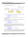
The following eTPU demos install by default with <%APPLICATION%>. This demos
also work in in the ETEC compiler run from the command line. Demo videos and tutorials
can be found at A demo is available at the following link. www.ashware.com/
product_videos.htm.
Freescale Set 1 - UART Demo
Use of the Freescale's Set12 UART function..
Use of header file, 'etec_to_etpuc_uart_conv.h' to convert between the
automatically generated 'etpuc_set1_defines.h' and the standard Freescale API
interface file.
Freescale Set 2 - Engine Demo
Use of the Freescale's Set2, Cam, Crank, Fuel, Spark, Knock functions.
Use of the identical auto-generated headers that Freescale uses for it's host-side
API
(C) 2007-2015
Toolk it User Manual, page 13
2. Demo Descriptions
Freescale Set 3 - ASDC Demo
Use of the Freescale's Set3 ASDC, PWMF, and PWMMDC functions.
Use of the identical auto-generated headers that Freescale uses for it's host-side
API
Freescale Set 4 - ASAC Demo
Use of the Freescale's Set12 ASAC, PWMF, and PWMMAC functions.
Use of ASH WARE's auto-defines file, 'etpuc_set4_defines.h'.
Data Types Demo
A variety of data types and data scopes commonly used in the eTPU.
Run-time initialization of data using the ETEC-generated initialization file,
'DataTypes_idata.h'.
Auto-Defines Demo
Use of files 'etec_sim_autodef.h' and 'etec_sim_autodef_private.h' to write &
verify channel, global, and engine memory. Note that engine memory is available
in the eTPU2 only.
Templates Demo
A variety of templates (empty code) which and are excellent starting point when
developing new eTPU functions.
Legacy and ETEC mode functions.
Standard and Alternate entry tables.
page 14, Toolk it User Manual
(C) 2007-2015
2. Demo Descriptions
System Configuration Demo
An (optional) system configuration file sets the system parameters such as clock
frequency, processor family, which functions run on which channels, channel
priority, etc.
Optionally, the maximum allowed worst case latency (WCL) for each channel can
be specified
Build fails if WCL requirements are not met.
Analyses file shows resulting system behaviours such as WCTL, and WCL for
each channel.
Stepper Motor System Simulator Demo
System simulator demo (both CPU and eTPU are simulated)
Freescale's host-side API on a simulated CPU.
The ASH WARE <>_defines file used in the host-side API.
Freescale's Set 1 Stepper Motor (SM) function.
UART ETEC Mode System Simulator Demo
System simulator demo (both CPU and eTPU are simulated.)
Use of the superior ETEC mode style of programming.
Conversion of Freescale's UART function to ETEC mode.
Freescale's host-side API used on a simulated CPU.
The Auto-generated header files similar to those used in the Freescale standard
functions.
The ASH WARE generated '<>_idata.h' file for initializing DATA memory.
(C) 2007-2015
Toolk it User Manual, page 15
2. Demo Descriptions
The ASH WARE generated '<>_scm.h' file for initializing CODE memory.
page 16, Toolk it User Manual
(C) 2007-2015
3. Build Process
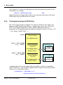
3
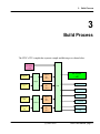
Build Process
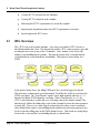
The ETEC eTPU compiler has separate compile and link stages as shown below.
Byte Craft
Executable
(.COD)
Elf/Dwarf
(.elf)
Object
File
(.eao)
Source File
(.c)
Compile
Object
File
(.eao)
Source File
(.c)
<>_defines.h
Link
<>_idata.[c,h]
<>_scm.[c,h]
Object
File
(.eao)
Source File
(.sta)
<>_ana.html
Assemble
Source File
(.sta)
Object
File
(.eao)
(C) 2007-2015
.lst.
.map
Toolk it User Manual, page 17
3. Build Process
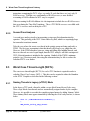
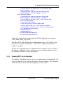
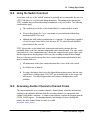
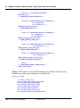
An explicit link stage is required even when compiling a single .c source file. All tools in
the ETEC toolkit are Windows command line executables. No GUI IDE comes with the
ETEC toolkit, however, many IDEs can be configured to use the ETEC compiler, e.g.
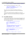
Eclipse, MS DevStudio, and PSPad, to name just a few. Here at ASH WARE we often
use Windows batch scripts or makefiles and a make utility such as GNU make in order to
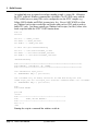
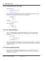
build eTPU code. Our demos typically use Windows batch scripts (.bat files); below is the
batch script that builds the ETEC UART function demo.
echo off
setlocal
set CC="..\..\ETEC_cc.exe"
set ASM="..\..\ETEC_asm.exe"
set LINK="..\..\ETEC_link.exe"
if exist %CC% goto DoneCheckPathing
set CC="..\..\Gui\testfiles\ETEC_cc.exe"
set ASM="..\..\Gui\testfiles\ETEC_asm.exe"
set LINK="..\..\Gui\testfiles\ETEC_link.exe"
:DoneCheckPathing
echo ++++++++++++++++++++++++++++++++++++++++++++++++++++++++++++++++++
echo RUNNING: %CD%\Mk.bat AT %TIME%
echo ++++++++++++++++++++++++++++++++++++++++++++++++++++++++++++++++++
%CC% -WarnDis=110 etpuc_uart.c
if %ERRORLEVEL% NEQ 0 ( goto errors )
rem -forcedemo only for demos; should not be used when doing real work
%LINK% etpuc_uart.eao -out=etpuc_uart -etba=0x0 -CodeSize=0x800 -lst -forcedemo
if %ERRORLEVEL% NEQ 0 ( goto errors )
echo .
echo BUILD PASSES
goto end
:errors
echo *************************************************
echo
YIKES, WE GOT ERRORS!!
echo *************************************************
exit /b -1
:end
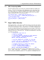
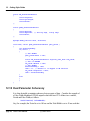
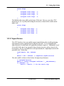
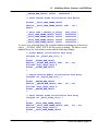
Running the script in a command line windows results in:
page 18, Toolk it User Manual
(C) 2007-2015
3. Build Process
3.1
Inputting .COD files
A .COD file can be used as an input to the ETEC linker.
The .COD global memory accesses cannot be determined directly from the .COD file.
Therefore this information must be provided to the linker using a command line options.
See Command Line Options section of the reference manual for information on specifying
the global memory boundaries
3.1.1
Limitations
Code that dereferences functions must disable code relocation AND disable optimizations
because this is not extractible.
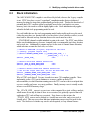
3.2
Pathing in the Executable
When generating the executable image file (.elf or such) pathing information is included
that allows the debugging tool (simulator or debugger) to find the source code that created
the executable image file. All source code pathing information is stored relative to the
(C) 2007-2015
Toolk it User Manual, page 19
3. Build Process
linking directory in which the executable image file is generated. This allows directory trees
to be moved and the source code can be located by the debugging tools as along as all
directories (source code and executable output image) are moved together. Note that the
linker can output the executable image and associated output files to a different directory
than that in which the linking is done, but that is not recommended as it can create a
disconnect between the source files and executable image.
Example 1. All source code and the executable output file are in the same directory.
This is the most simple and common case. Because the source code and executable code
are in the same directory no directory information is included with the source code
information.
Input File:
c:\SomeDirectory\foo.c [input to linking as foo.eao]
Link Directory and Output File:
c:\SomeDirectory\output.elf
Source Code Pathing Information:
foo.c
Example 2. Source code is in the same drive, but up one sub-directory and down another
sub directory.
Input File:
c:\SomeDirectory\SubDirA\foo.c [input to linking as ..\SubDirA\foo.eao]
Link Directory and Output File:
c:\SomeDirectory\SubDirB\output.elf
Source Code Pathing Information:
..\SubDirA\foo.c
Example 3. Source code is in a different drive from the executable output image file.
Note that in this case since the source code is on a completely different drive, the entire
path to the source code is retained.
Input File:
page 20, Toolk it User Manual
(C) 2007-2015
3. Build Process
L:\DriveLDir\foo.c [input to linking as L:\DriveLDir\foo.eao]
Link Directory and Output File:
N:\DriveNDir\output.elf
Source Code Pathing Information:
L:\DriveLDir\foo.c
It is therefore ideal to have the link done in the executable image file's ultimate destination
rather than moving it after it has been generated. However, if you must move the
executable file after it has been generated then you may need to specify the source file
location in your simulator or debugger. In the ASH WARE simulator this is in the 'Options'
menu under the 'Source Code Search Path' sub menu.
(C) 2007-2015
Toolk it User Manual, page 21
page 22, Toolk it User Manual
4. Memory Map
4
Memory Map
The eTPU has separate code and data address spaces. These separate code and data
spaces base their memory at address zero.
(C) 2007-2015
Toolk it User Manual, page 23
4. Memory Map
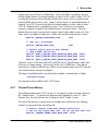
4.1
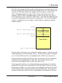
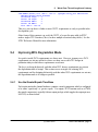
Code Memory Map
Code memory has two primary components, Entry Table and Code Memory as seen
below.
0x0000
Entry Table
End of Used Entry Table
Unused Entry Table
0x0800
Code Memory
End of Used Code Memory
Unused Code Memory
End Of SCM (0x1800)
As seen in the above diagram, the entry table base defaults to address zero. As eTPU
Functions and eTPU Classes are added, they are fill towards address 0x800.
The entry table base address can be overridden using the -etba=<ADDR> linker command
line option, where the address must be a multiple of 0x800. It is generally best to keep the
entry table base address at address zero (default.) If the entry table base address is
overridden, code memory fills both above and below the entry table.
page 24, Toolk it User Manual
(C) 2007-2015
4. Memory Map
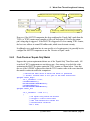
The eTPU code (opcodes) defaults to address 0x800 and grows towards the end of SCM.
Note that the end of SCM varies from one microcontroller to the next. The default, which
is shown, is 0x1800 (6K) and this is the smallest amount of memory currently on any
eTPU. More typical amounts are 16K or 24K; to increase the memory size use the CodeSize=<BYTES> linker command line option. As the code size grows, the ‘End of
Used Code Memory’ grows towards the ‘End of SCM.’ Once this is hit, additional growth
occurs in the unused portion of the entry table, as shown below. The code’s base address
can not be overridden because the designers could not think of a situation in which this
would be required.
0x0000
Entry Table
End of Used Entry Table
Unused Entry Table
End of Used Code Memory
0x0800
Code Memory
End Of SCM (0x1800)
The entry table is effectively an array of thread-start address pointers. Unused entry table
is filled with pointers to the Error Handler Library. This allows observability of accidental
access of entry table because the corresponding bit in the _Global_error_data gets set.
Unused code memory (SCM) gets filled with ‘goto’ opcodes where the goto destination is
a handler in the Error Handler Library. This allows observability of run-away code
because the corresponding bit in the _Global_error_data gets set.
Unused entry table could be accessed inadvertently by a programming error in which an
unused eTPU Function or Class is specified on CxCR.CFS register. However, this same
unused memory could be accessed by runaway code, bringing in to question the decision to
treat unused entry table as unused entry table and not unused opcodes. The rationale for
treating it as unused entry table is because a programming error is thought to be far more
(C) 2007-2015
Toolk it User Manual, page 25
4. Memory Map
likely than runaway code.
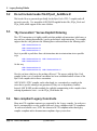
4.2
Data Memory Map
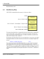
ASH WARE recommends that data memory be is laid out as follows.
0x0000
Global Data
End of Global Data
Stack / Scratchpad /
Engine Data
End of Stack / Scratchpad / Engine Data
Channel Data
End of Channel Data Memory
Spare RAM Memory
End Of DATA RAM (0x600)
The memory layout listed above is supported by the many #defines that are automatically
generated by the linker. These #defines are found in the auto-defines file which is the
same as the output ELF/DWARF file (unless overridden or disabled) except that the file
suffix (.ELF) is replaced with ‘_defines.h’.
The following auto-define indicates the size of the Global Data. Note that since the Global
Data begins at address zero, this is also the start of the Stack / Scratchpad / Engine Data
memory.
#define _GLOBAL_VAR_SIZE_
0x04
The section of memory below the Global Data holds one or more of Stack, Scratchpad,
and/or Engine Data. These reflect three different programming models. Somewhat
interestingly, the ETEC compiler supports mixing and matching of multiple of these models.
These are all used to hold dynamic local variables that overflow the available register set,
and dynamic local variables stored in registers that must be saved when ‘C’ functions are
called.
page 26, Toolk it User Manual
(C) 2007-2015
4. Memory Map
4.2.1
Global Data
Say the current engine speed needs to be able to be read by all code in all channels and in
both eTPU engines. This can be done by declaring a global variable named
‘EngineSpeed’. To make ‘EngineSpeed’ global, it must be declared outside of any
function, as follows.
// Declare outside of any eTPU Function,
// Class, or ‘C’ function
int EngineSpeed;
void MyFunction()
{
int SomeVar = EngineSpeed;
<More Code>
}
4.2.2
The Global Scratchpad
The ETEC compiler supports storing in Scratchpad memory, dynamic local variables that
overflow the available register set, and dynamic local variables stored in registers that must
be saved when ‘C’ functions are called. Under the default stack-based programming
model, these automatic variables would go on the stack, but when the Scratchpad model is
enabled, such items are allocated from static, global memory addresses.
Using scratchpad memory has a slight advantage over a stack-based approach in that it
produces somewhat tighter code than stack due to limitations in the eTPU instruction set.
However, the scratchpad has a significant disadvantage in that it cannot be used on code
that runs simultaneously in both eTPU engines. This is known as the ‘eTPU Scratchpad
Bug’ and is explained in the following section.
The auto-defines file includes a macro for the size of global scratchpad.
#define _GLOBAL_SCRATCHPAD_SIZE_
0x10
It also includes a macro for the total global allocation, which includes both user-declared
global data, and global scratchpad, if any.
#define _GLOBAL_DATA_SIZE_
(C) 2007-2015
0x14
Toolk it User Manual, page 27
4. Memory Map
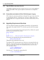
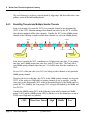
4.2.3
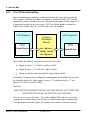
The eTPU Scratchpad Bug
The Scratchpad memory model has an inherent bug when the same code is run in both
eTPU engines, AND that code utilizes scratchpad. Consider the PWM eTPU Function
shown below which is running at the exact same time in both engine A and in engine B. It
is important to not that it is the exact same eTPU Code in both engines, and therefore
dynamic local variable ‘MyVar1’ is stored at the exact same address.
eTPU Engine A
eTPU Engine B
Common
Scratchpad
Memory
PWM
Read/Write
PWM
int MyVar1;
@Addr 0x240
int MyVar2;
Read/Write
Now consider the following events that occur in this exact order.
Engine A writes a ‘5’ to MyVar1 (address 0x240)
Engine B writes a ‘10’ to MyVar1 (address 0x240)
Engine A reads the value from MyVar1 (again, address 0x240)
Recall that scratchpad is used for things like storing dynamic local variables that overflow
the available registers set. Since engine A wrote a ‘5’ it should read back a ‘5’, but
instead a ‘10’ is read, THIS IS A BUG!
Therefore:
THE SCRATCHPAD MODEL SHOULD ONLY BE USED ON eTPU CODE THAT
ONLY EXECUTES IN ONE OF THE TWO eTPU ENGINES!
There are two caveats to the above. First, if the compiled eTPU code does not end up
requiring any scratchpad usage, then of course it can run in both engines simultaneously.
Carefully designed code that requires few dynamic local variables, and makes only one-
page 28, Toolk it User Manual
(C) 2007-2015
4. Memory Map
deep no-argument function calls can achieve this. Second, the designer can make use of
eTPU hardware semaphores to protect engine-engine conflicts in threads that utilize
scratchpad. The drawback is that this effectively doubles the worst-case thread length of
such threads and requires more error-prone direct user intervention (e.g. a later code
maintainer introduces a scratchpad variable into a thread that didn’t need/have semaphore
protection previously).
The Scratchpad model is specified on the ETEC compiler’s command line as follows.
-globalScratchpad
It is possible to mix both scratchpad and stack by compiling some eTPU Functions and
Classes with scratchpad and others using stack. This is useful because when there is a
mix of functions, some of which must execute on both eTPU engines (and therefore are
compiled to use stack) and others that will only ever run on one of the engines (and
therefore can be compiled using the more optimal scratchpad.)
4.2.4
The Stack
The ETEC compiler also supports a classic stack similar to that seen in CPU’s. The stack
grows and contracts as needed during each thread. As mentioned previously, the stack
holds dynamic local variables that overflow the available register set, and dynamic local
variables stored in registers that must be saved when ‘C’ functions are called.
(C) 2007-2015
Toolk it User Manual, page 29
4. Memory Map
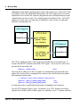
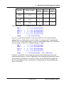
Although the stack model currently produces larger code in some cases (between 0% and
10% larger) it offers the significant advantage that each eTPU engine gets its own stack
and therefore does not have the coherency bug inherent in the Scratchpad memory model
explained in the previous section. The example shown below illustrates this. Each eTPU
engine gets its own stack, so reads/writes to within these stack can never overlap and
therefore are intrinsically safe.
eTPU Engine A
PWM
eTPU A Stack
Read/Write
int MyVar1;
@Addr 0x240
int MyVar2;
eTPU Engine A
eTPU B Stack
PWM
int MyVar1;
@Addr 0x240
int MyVar2;
Read/Write
The ETEC compiler performs a static analysis to determine the stack requirements. It
assumes that all eTPU functions run in both eTPU engines. The worst-case stack size is
provided in the auto-defines file.
#define _STACK_SIZE_
0x34
The stack bases addresses for the two engines are automatically generated in the autodefines file as shown below, assuming the user wants to place stack directly after global
allocation in the memory map.
// Default stack base address definitions
#define _ETPU_A_STACK_BASE_ADDR
0x4
#define _ETPU_B_STACK_BASE_ADDR
0x38
In reality, the stack(s) could be allocated anywhere, including the top of memory.
Not all eTPU functions require a stack. For instance, if an eTPU function can fit all its
dynamic local variables in the available register set, and there are no ‘C’ function calls that
page 30, Toolk it User Manual
(C) 2007-2015
4. Memory Map
trigger stack usage in any thread, then the stack is not required by that function. For
instance, none of Freescale’s Set 1-4 eTPU functions require a stack.
When a stack is required the ETEC compiler generates a stack pointer that is part of the
eTPU function/class channel frame. This stack pointer must be initialized in each channel
instance of the eTPU function/class. Since a stack may or may-not be required (and the
same code might require a stack in one compiler release, but not in the next) it is a good
idea to use the following #ifdef to provisionally initialize the stack with the appropriate
stack pointer.
In the following example a PWM function that may (or may not) require a stack is given a
reference to the stack base. This is done for a channel in each of the eTPU engines.
// init the stack frame for a channel on eTPU Engine A
#ifdef _CPBA24_PWM___STACKBASE_
write_chan_data24 (CHAN_27, _CPBA24_PWM___STACKBASE_,
_ETPU_A_STACK_BASE_ADDR);
#endif
//
// init the stack frame for a channel on eTPU Engine B
#ifdef _CPBA24_PWM___STACKBASE_
write_chan_data24 ( CHAN_25, _CPBA24_PWM___STACKBASE_,
_ETPU_B_STACK_BASE_ADDR);
#endif
Since the Stack memory model is the default, no command line argument is required to
select it.
4.2.5
Engine-Relative Address Space (eTPU2 Only)
The eTPU2 processor introduces a new type of memory address space, referred to as
“Engine-Relative”. Variables or other data allocated in engine-relative space are accessed
via an offset specified by the eTPU2’s new Engine Relative Base Address (ERBA) field.
Each engine has its ECR.ERBA, thereby supporting two different offsets. This allows
code running on each engine to see an engine-only copy of static data; it also allows the
same code, which utilizes static memory allocation for scratchpad, to run independently on
each eTPU engine without conflict. This latter feature is known as “Engine Scratchpad”,
and is discussed further in the next section. Users can declare global/static variables to be
allocated out of engine-relative space using the _ENGINE address space qualifier.
int _ENGINE e_s24;
User-defined engine-relative variables are allocated starting at the base of engine-relative
(C) 2007-2015
Toolk it User Manual, page 31
4. Memory Map
space (limited to 512 bytes); the following macro in the auto-defines file provides the size
used by these user variables.
#define _ENGINE_VAR_SIZE_
0xA4
Further information on engine-relative address space placement with respect to the entire
SDM memory map is provided in the next section.
4.2.6
The Engine Scratchpad (eTPU2 Only)
The eTPU2 supports Engine Scratchpad. The Engine Scratchpad is quite similar to the
global scratchpad with one major difference. Since memory accesses are offset by the
eTPU2’s new Engine Relative Base Address (ERBA) field and the offsets are
independent, the Scratchpad bug inherent in global scratchpad is avoided. See below. [JD
-> AK : change “@Addr” below …]
0x0000
Global Variables
int MyGlobalVar;
0x200 * ECR_A.ERBA
(e.g., 0x200)
Engine Variables
(eTPU A)
int MyEngineVar;
@Addr 0x200
0x200 * ECR_B.ERBA
(e.g., 0x400)
Engine Variables
(eTPU B)
int MyEngineVar;
@Addr 0x400
eTPU Engine A
PWM
Read/Write
Read/Write
eTPU Engine B
PWM
Read/Write
Read/Write
A significant drawback of using engine-relative base address register is its granularity
which is 0x200 bytes. This can lead to significant RAM wastage. The true (byte) address
of any access is calculated as follows
trueAddress = (ECR.ERBA << 9)
+ Engine-Relative-Access-Address;
page 32, Toolk it User Manual
(C) 2007-2015
4. Memory Map
Suppose there are 0x20 bytes of Global Data. Due to the ERBA’s granularity, the next
possible Engine-Relative scratchpad boundary is address 0x200, so this is where eTPU A’s
scratchpad is located per the auto-defines default (users can of course override this and
program ERBA however they want). Suppose only 0x30 bytes of Scratchpad memory is
required. For eTPU B, the next possible scratchpad boundary is 0x400, so this is where
eTPU B’s Engine-Relative scratchpad base goes. Since 0x30 bytes of scratchpad
memory is required for engine B, the Channel Frames can begin at 0x430. The autodefines file macros that are generated to support engine-relative address space are show
below, and are in addition to engine user variable size described in the previous section.
#define _ENGINE_SCRATCHPAD_SIZE_
0x00
// user var + scratchpad
#define _ENGINE_DATA_SIZE_
0xA4
// Default engine-relative base address
// (ECR_X.ERBA) definitions
#define _ETPU_A_ENGINE_1ETPU_RELATIVE_BASE_ADDR
#define _ETPU_A_ENGINE_2ETPU_RELATIVE_BASE_ADDR
#define _ETPU_B_ENGINE_2ETPU_RELATIVE_BASE_ADDR
0x200
0x200
0x400
Therefore, it takes 0x430 bytes of RAM to hold 0x20 bytes of global memory, and 2 times
0x30 bytes of engine memory. The wastage in this case is 0x3B0 bytes. Note that an
advanced user could carefully fill some of these wasted memory gaps with eTPU function/
class channel frames (advanced technique).
The Engine Scratchpad model is specified on the compiler’s command line as follows.
-engineScratchpad
Note that this is only available for the eTPU2 target.
4.2.7
Channel Frame Memory
Each channel running in the eTPU can have it’s own private section of memory known as
the ‘Channel Frame.’ As shown in the diagram at the beginning of section 3.2, ‘Data
Memory Map’ this located below the ‘Scratchpad / Stack / Engine’ section.
The start of this memory section is known at compiler time, and therefore the following
#defines are generated in the auto-defines file.
// Default channel frame base address definitions
// One for the single eTPU case, one for the dual eTPU case
#define _CHANNEL_FRAME_1ETPU_BASE_ADDR 0x108
(C) 2007-2015
Toolk it User Manual, page 33
4. Memory Map
#define _CHANNEL_FRAME_2ETPU_BASE_ADDR
0x208
Interestingly, the start of Channel Frame memory depends on whether there are one, or
two eTPU engines, since the stack section and engine-relative sections (if any) require
per-engine allocations. Therefore, two #defines are generated (above;) the first is for a
single eTPU microcontroller, the second is for a dual eTPU microcontroller.
The amount of memory required by each channel depends on the eTPU Function or Class
running on that channel. For instance, a SPARK channel frame might be 0x28 bytes and
PWM channel frame might be only 0x8 bytes. Therefore a system with lots of SPARKs
running on many channels would require a far larger Channel Frames Data section than
(say) a system comprised mostly of PWM’s.
Becase the configuration of which functions are running on which channels is often not
known at compile time, the total amount of Channel Frame Data memory is generally also
not known. Therefore the total Channel Frame Data size is not in the Auto-Defines file.
However, the amount of Channel Frame memory required by each eTPU Function or
Class is known at compiler time. This is shown as follows.
// Channel Frame Size,
// amount of RAM required for each channel
// CXCR.CPBA (this) = CXCR.CPBA (last) + _FRAME_SIZE_PWM_;
#define _FRAME_SIZE_PWM_
0x08
The channel frame is normally built at run-time. Beginning at the Channel Frame Base
Address, each channel is allotted a channel frame using the frame size from above. An
example of two PWM’s and two SPARK’s in a two eTPU engine system is shown below.
page 34, Toolk it User Manual
(C) 2007-2015
4. Memory Map
Channel Frames
_CHANNEL_FRAME_2ETPU_BASE_ADDR
PWM On Chan0
CXCR.CPBA = (above) + _FRAME_SIZE_PWM_
PWM On Chan4
CXCR.CPBA = (above) + _FRAME_SIZE_PWM_
SPARK On Chan1
CXCR.CPBA = (above) + _FRAME_SIZE_SPARK_
SPARK On Chan5
CXCR.CPBA = (above) + _FRAME_SIZE_SPARK_
(End of Channel Frames)
Unused DATA Memory
End Of SCM (0x1800)
(C) 2007-2015
Toolk it User Manual, page 35
page 36, Toolk it User Manual
5. Legacy Porting Pitfalls
5
Legacy Porting Pitfalls
When porting your code from the Byte Craft compiler to the ASH WARE compiler a
number of issues must be understood for the effort to be successful
5.1
The @ Symbol
The @ symbol is used in the Byte Craft compiler to overlay structures on top of registers
or locate objects at specific addresses. This is not standard C and is not supported by
ETEC.
ETEC follows C99 (TR18037) for mapping of a structure unto a register using the
following syntax (example):
struct tpr_struct {
unsigned int16 TICKS
unsigned int16 TPR10
unsigned int16 HOLD
unsigned int16 IPH
unsigned int16 MISSCNT
unsigned int16 LAST
} register _TPR tpr_reg;
:
:
:
:
:
:
10;
1;
1;
1;
2;
1;
The variable ‘tpr_reg’ is given type ‘struct tpr_struct’ and assigned to the TPR register
using the named register syntax ‘register _TPR’.
(C) 2007-2015
Toolk it User Manual, page 37
5. Legacy Porting Pitfalls
5.2
Do not include header file ETpuC_AshWare.h!
This header file was generated specifically for the Byte Craft eTPU C compiler and will
not work correctly. Use instead the ASH WARE supplied header files, ETpu_Hw.h and
ETpu_Std.h, which support all the same #defines.
5.3
“By Convention” Versus Explicit Ordering
The eTPU instruction set is highly parallel such that multiple sub instructions (which may or
may not have ordering dependencies) can be packed into a single instruction. For example,
suppose that the code generates the following three sub-instructions in the following order.
Sub Instruction A
Sub Instruction B
Sub Instruction C
Say it is possible to pack these three sub instructions into two instructions in two possible
ways
Sub Instruction A, Sub Instruction B
Sub Instruction C
Or this way
Sub Instruction A
Sub Instruction B, Sub Instruction C
How do you know which way the packing will occur? The answer with the Byte Craft
compiler is that a set of consistent conventions has been established and all versions of the
Byte Craft compiler stick to these conventions.
ASH WARE’s ETEC compiler, on the other hand, is a convention-less compiler in the
sense that a specific ordering is not guaranteed IF they are no dependency conflicts.
Instead, ASH WARE provides methods for explicitly communicating to the compiler where
ordering dependencies exist – see the ETpu_Lib.h header file.
5.4
Non compliant Legacy Constructs
Many non-C99 compliant constructs are supported by the Legacy compiler. In such cases
there is an impossible to resolve conflict between Legacy compliance and C99 compliance.
In such un-resolvable cases, ETEC has chosen to be C99 compliant rather than legacy
compiler compliant and to document non-compliance legacy issues here.
page 38, Toolk it User Manual
(C) 2007-2015
5. Legacy Porting Pitfalls
5.4.1
Signed Division
With the legacy compiler, division of signed integer types generates the same code as
unsigned integer types. However, if either operand is actually negative the result is
incorrect. ETEC generates correct code for signed division, but it is much less efficient. It
is recommended that if the operands do not actually need to be signed, that they be given
unsigned types or typecast to unsigned before the division to result in better code.
5.4.2
Fract – Integer multiplication
Per TR18037, the result of a Fract – Integer multiplication is of type Fract and represents
the fractional portion of the result. Most eTPU users actually want the integer portion of
the result, which can be gotten using the muli<>() library functions. The Legacy compiler
does not follow TR18037 and returns the integer portion of a Fract – Integer multiply.
ETEC users must use the muli<>() library functions to get the same result.
5.4.3
Parameter argument lists separated by commas, etc.
Various small syntax issues are likely to be encountered that are easily fixed such as
comma separators. Consider the declaration of three integer variables, as follows.
int x, y, z;
This may or may not be compliant depending on where the declaration occurs. If the
declaration occurs within a function body, as follows, this is fine.
Void MyFunc()
{
int x, y, z;
< ... >
}
The problem is that this is not allowed in all situations. For example, when declared in the
function argument, as follows, the syntax is not compliant.
// This is non-compliant
// It will result in a compilation error in ETEC
// even though the legacy compiler allows it
Void MyFunc(int x, y, z )
{
< ... >
}
(C) 2007-2015
Toolk it User Manual, page 39
5. Legacy Porting Pitfalls
5.4.4
Signed bitfields cause sign extension
Using bitfields of signed type in ETEC is expensive because accesses of these bitfields are
properly sign extended. Unless signed is required, it is much better to use unsigned for
bitfields.
5.4.5
Enumerations are treated as 8-bit or 24-bit data types in Legacy
ETEC will pack an enumeration variable into an 8-bit unit if the range of enum values fit in
an 8-bit signed unit, otherwise a 24-bit unit is used. The legacy compiler appears to do
something similar, but it is not guaranteed that the same data size will be used by ETEC in
all cases.
5.5
Exporting Preprocessor Directives
ETEC does support the #pragma write technique for host interface code generation; the
below applies when using the default ETEC auto-header generation rather than #pragma
write.
In legacy code, it is not uncommon for the constant generated by a #define to be exported
into the auto-generated header file, as follows.
#define INIT_HSR 7
<...>
<...>
<...>
#pragma write h, ( ::ETPUliteral(#define ETPU_INIT_HSR) INIT_HSR );
This generates the following #define in the auto generated header file.
#define ETPU_INIT_HSR 7
Whoopdie doo, did I mention that my leg is a leg?
The problem in ETEC is that the preprocessor’s directives are not exported into the auto
defines file. Instead, #defines that are needed by both the host-CPU and the eTPU side,
must be moved into their own header file and included into both the host-side and the
eTPU side builds as follows.
// File: CommonDefines.h
#define INITIALIZE_HSR 7
In the host side “C” file, include the common defines file.
// File: HostSideDriver.c
page 40, Toolk it User Manual
(C) 2007-2015
5. Legacy Porting Pitfalls
#include “CommonDefines.h”
<...>
<...>
write_chan_hsrr( TEST_CHAN_ASM1, INITIALIZE_HSR);
Similarly, on the eTPU side “C” file, include the same common defines file.
// File: eTPUFunction.c
#include “CommonDefines.h”
<...>
<...>
void MeasurePulse ( int24 PulseWidth, int24 PulseAccum )
{
if ( hsr == INITIALIZE_HSR)
{
// Thread that handles the hsr==7 event here.
<...>
5.6
Include headers
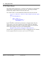
The eTPU_C system uses the standard header file named “etpuc.h.” and or
“etpuc_common.h”. The equivalent files in ETEC are “ETpu_Hw.h” and “ETpu_Std.h.”
At the top of your source code you can use ETEC’s built-in #define __ETEC__ to make
your source code compatible with both the ETEC and eTPU_C.
#ifdef __ETEC__
#include <ETpu_Std.h>
#else
#ifndef __ETPUC_H
#include <etpuc.h>
#endif
/*Defines eTPU hardware*/
(C) 2007-2015
Toolk it User Manual, page 41
page 42, Toolk it User Manual
6. Modifying existing host-side driver code
6
Modifying existing host-side
driver code
For the most part, existing host-side eTPU driver code will function as-is with ETEC, the
main change required being that a different set of macro names need to be used for
address offsets, etc. The sections below document where modifications are likely to be
needed.
6.1
Auto-Defines Header File
The ETEC auto-defines mechanism outputs all compiler generated interface information
into a header file referred to as the “defines file”. Existing tools and code used a technique
called “#pragma write” in order to generate this data for use by host-side drivers. In
virtually all cases there is a one-for-one match between auto-generated macros in the
defines file, and macros generated via manually coded “#pragma writes”, however, the
macro names will almost certainly be different. ETEC uses a well-defined algorithm to
generate the macro names; see the reference manual for details. Transitioning to ETEC
for the most part just requires the defines file be included, and macros being referenced
changed to the auto-defines names.
For example, a line of code such as
// write match_rate calculated from time base
// frequency and desired baud rate
(C) 2007-2015
Toolk it User Manual, page 43
6. Modifying existing host-side driver code
*(pba + ((FS_ETPU_UART_MATCH_RATE_OFFSET - 1) >> 2))
= chan_match_rate;
Would become
*(pba + ((_CPBA24_UART_FS_ETPU_UART_MATCH_RATE_ - 1) >> 2))
= chan_match_rate;
The macros that typically need replacement include:
MISC value
Entry table base address
Function numbers
Function entry types
Channel (function) frame sizes
Data (parameter) address offsets
6.1.1
Auto-Struct Header File
The ETEC auto-struct capability provides another way to read/write the eTPU shared data
memory from the host. See the reference manual for details.
6.2
Auto-Header Pass-Through
Unfortunately, a not particularly clean method for exporting information for things like HSR
numbers gained traction in the eTPU community and this is not supported by the ETEC
compiler when using the default auto-defines header. The HSR number is defined at the
top of the ‘C’ file, then used in the entry table’s if/else array, and then is exported into the
auto-generated file, as follows.
#define INIT_TCR1_HSR_NUM 7
< ... >
if ( hsr == INIT_TCR1_HSR_NUM )
< ... >
#pragma write h, #define FS_INIT_TCR1_HSR INIT_TCR1_HSR_NUM );
With the ETEC compiler, the HSR numbers should be defined in their own header file.
This header file is then included in both the eTPU-side and host-side source code.
page 44, Toolk it User Manual
(C) 2007-2015
6. Modifying existing host-side driver code
6.3
Stack Initialization
The ASH WARE ETEC compiler is stack based by default, whereas the Legacy compiler
is not. ETEC does have several “scratchpad” compilation modes that use dedicated
memory locations for items that would normally go on the stack. This has the drawback of
potential dual-eTPU conflicts (global scratchpad; more below) and tends to use more
memory, but it also tends to result in slightly tighter code. Stack initialization only applies
when the default stack programming model is used.
For code builds that use the stack programming model, and actually need to use the stack
(either because there are function calls or because there is local variable overflow) a stack
must both be allocated and any functions that use the stack must have their
__STACKBASE channel variable initialized to point at the stack. The ETEC auto-defines
makes stack initialization easy because it outputs both a recommended stack base location,
and a stack size. Additionally, it outputs macros for the start of channel frame allocation,
which take into account the stack size; see below.
// Amount of DATA RAM (in bytes) required for the stack
// (ideally, programs require none)
// #define CHANNEL_FRAME_START (((_GLOBAL_DATA_SIZE_ + \
_STACK_SIZE_) + 7) & ~7)
#define _STACK_SIZE_
0x20
// Default stack base address definitions
#define _ETPU_A_STACK_BASE_ADDR
0x84
#define _ETPU_B_STACK_BASE_ADDR
0xa4
// Default channel frame base address definitions
// One for the single eTPU case, one for the dual eTPU case
#define _CHANNEL_FRAME_1ETPU_BASE_ADDR 0xa8
#define _CHANNEL_FRAME_2ETPU_BASE_ADDR 0xc8
Why is ETEC stack-based? For one, it results in a more C99 compliant compiler. More
importantly, on the eTPU part it eliminates a resource conflict on dual-eTPU
microcontrollers, in which functions running on each eTPU can have their scratchpad data
accesses conflict and cause very nasty problems. Finally, in many cases it actually results
in lower overall SDM memory usage.
The _STACK_SIZE_ macro is a worst-case value computed by a static call-tree analysis,
which means it can only be done if there is no recursion (it is generally expected that real
application eTPU code will not use recursion). Note, however, that at times the
_STACK_SIZE_ macro can be defined to a (small) non-zero value, and yet, no stack is
actually used. This can occur when link-time optimization removes any last need for the
stack. The final test of whether any stack is used/required, is if any channel frames
(C) 2007-2015
Toolk it User Manual, page 45
6. Modifying existing host-side driver code
contain __STACKBASE variables. The best way to write host code that initializes
channel frame stack values is with conditional compilation, such as
// “DefinesTest” function stack initialization, for channel
// DT_CHAN_NUM (only if needed)
#ifdef _CPBA_TYPE_DefinesTest___STACKBASE_
etpu_set_chan_local_24(DT_CHAN_NUM,
CPBA_TYPE_DefinesTest___STACKBASE_,
_ETPU_A_STACK_BASE_ADDR);
#endif
6.4
Pin Direction
The entry table can use either the input or output pin for event vector handling (but not
both.) This is specified in the entry table definition in ETEC mode. But in order to select
the entry table, each channel’s CxCr.ETPD field must be initialized. The auto header file
capability spits out the value for this.
6.5
Code Image and Initialized Data
ETEC auto-generates everything needed to initialize eTPU code and data memory. The
typical way this has been done is to place the code image and initialized data (global) into
arrays that are included in the host side build, often named “etpu_code” and
“etpu_globals”. With ETEC, this data, in initialized arrays, is automatically generated into
the “<>_scm.c” and “<>_idata.c” files which can be included into the eTPU initialization
code, like
#include "etpu_image_scm.c"
#include "etpu_image_idata.c"
The initialized arrays can then be referenced in the call to the standard Freescale eTPU
initialization function.
/* initialize eTPU hardware */
fs_etpu_init (my_etpu_config, (uint32_t *) _SCM_code_mem_array,
sizeof (_SCM_code_mem_array),
(uint32_t *) _global_mem_init,
sizeof (_global_mem_init),0);
page 46, Toolk it User Manual
(C) 2007-2015
7. Using Auto-Defines to Allocate eTPU Data Memory
7
Using Auto-Defines to Allocate
eTPU Data Memory
The auto-defines file provides a number of macros that are useful for allocating eTPU data
memory. Some are not optional, such as where global variables and global scratchpad (if
any) have been allocated. Others are optional, such as stack location (if any) and the base
of channel frame memory; however, the default values typically provide the best
performance from a memory usage standpoint.
// Total Global Data Size
// (starts at address 0,
//
includes any global scratchpad allocation)
// address (end) = SPRAM + _GLOBAL_DATA_SIZE_
#define _GLOBAL_DATA_SIZE_
0xB8
// Total Engine Data Size (starts at engine address 0,
//
includes any engine scratchpad allocation)
// address (end) = ((ECR_X.ERBA)<<9) + _ENGINE_DATA_SIZE_
#define _ENGINE_DATA_SIZE_
0xB4
// Amount of DATA RAM (in bytes) required for the stack
// (ideally, programs require none)
// #define CHANNEL_FRAME_START (((_GLOBAL_DATA_SIZE_ + \
//
_STACK_SIZE_) + 7) & ~7)
#define _STACK_SIZE_
0x3C
(C) 2007-2015
Toolk it User Manual, page 47
7. Using Auto-Defines to Allocate eTPU Data Memory
// Default stack base address definitions
#define _ETPU_A_STACK_BASE_ADDR
0xb8
#define _ETPU_B_STACK_BASE_ADDR
0xf4
//
//
//
//
//
//
//
//
//
//
//
//
//
Note on _ENGINE_DATA_SIZE when it is non-zero
The ERBA for each eTPU engine can only be set
on a 512 byte boundary.
If _ENGINE_DATA_SIZE_ is significantly
smaller than 512 bytes, this
can lead to significant gaps in shared data memory (SDM)
usage if other memory usages, such as channel frames,
are not overlaid into these gaps.
Thus the default engine-relative base address values
specified below may not be optimal for a particular
application. The user should be knowledgeable regarding
this topic so they can configure the eTPU module
appropriately.
// Default engine-relative base address (ECR_X.ERBA) def's
#define _ETPU_A_ENGINE_1ETPU_RELATIVE_BASE_ADDR 0x200
#define _ETPU_A_ENGINE_2ETPU_RELATIVE_BASE_ADDR 0x200
#define _ETPU_B_ENGINE_2ETPU_RELATIVE_BASE_ADDR 0x400
// Default channel frame base address definitions
// One for the single eTPU case,
// one for the dual eTPU case
#define _CHANNEL_FRAME_1ETPU_BASE_ADDR 0x2b8
#define _CHANNEL_FRAME_2ETPU_BASE_ADDR 0x4b8
The recommended stack base addresses are defined with the macros
_ETPU_A_STACK_BASE_ADDR, and if a dual-engine system is in use,
_ETPU_B_STACK_BASE_ADDR. The ENGINE macros only are output if the code is
compiled for the eTPU2 AND engine-relative address space is used. Lastly,
recommended locations at which to start channel frame allocation are provided. Note that
two macros are provided, one for if a single-engine eTPU is in use, and the other for a
dual-engine eTPU.
Working from the channel frame base, channel frames can be allocated by using their
_FRAME_SIZE_<name>_ macros. This is straight-forward, but there are some times
other memory needs to be allocated – for the Coherent Dual-Parameter Controller (CDC)
temporary buffer, or other kinds of data buffers or even objects (structures). These cases
are discussed below.
page 48, Toolk it User Manual
(C) 2007-2015
7. Using Auto-Defines to Allocate eTPU Data Memory
7.1
CDC Temporary Buffer
The CDC temporary buffer is two words in size, and must be aligned on a double-word
boundary. Given that channel frames need be aligned the same way, the channel frame
base address values (e.g. _CHANNEL_FRAME_2ETPU_BASE_ADDR). Thus the
most convenient thing to do is allocate the CDC temporary buffer before any channel
frames are allocated, if CDC is to be used by the host.
eTPU->ETPUCDCR.PBASE = _CHANNEL_FRAME_2ETPU_BASE_ADDR >> 3;
uint8_t* etpu_chan_frame_mem = _CHANNEL_FRAME_2ETPU_BASE_ADDR + 8;
// allocate channel frames
uint8_t* etpu_pwm_cf = etpu_chan_frame_mem;
etpu_chan_frame_mem += _FRAME_SIZE_PWM_;
// ...
7.2
Object / Buffer Allocation
Allocating data buffers, or other objects, in eTPU data memory is best done after channel
frame allocation is done, if reasonable. This is because such allocations typically only need
to be done on word boundaries, whereas channel frames are all double-word aligned, and
since they are double-word sized, they stack cleanly on top of one another. Most of this is
fairly straight-forward, with the exception of allocating space for objects that are of struct/
union type (and arrays of such) in the eTPU. The defines file information on a struct/union
type includes the following:
// defines for type struct S1
// size of a tag type
// (including padding as defined by sizeof operator)
// value (sizeof) = _GLOB_TAG_TYPE_SIZE_S1_
#define _GLOB_TAG_TYPE_SIZE_S1_
0x08
// raw size (padding not included) of a tag type
// value (raw size) = _GLOB_TAG_TYPE_RAW_SIZE_S1_
#define _GLOB_TAG_TYPE_RAW_SIZE_S1_
0x07
// alignment relative to a double even address
// of the tag type (address & 0x3)
// value = _GLOB_TAG_TYPE_ALIGNMENT_S1_
#define _GLOB_TAG_TYPE_ALIGNMENT_S1_
0x01
Since a struct/union type on the eTPU can have unusual alignment and size, the above
macros - _SIZE_, _RAW_SIZE_, _ALIGNMENT_ - need to be used to properly allocate
space for the object and initialize a pointer to it. The equation for calculating the byte size
(C) 2007-2015
Toolk it User Manual, page 49
7. Using Auto-Defines to Allocate eTPU Data Memory
needed, allocated on a words boundary, is
Allocation size = (_RAW_SIZE_ + _ALIGNMENT + 3) & ~3
A pointer to the object (on the eTPU-side) is then computed as
Pointer = Allocation Address (word boundary)
+ _ALIGNMENT
An array of struct/union type would be allocated with a slightly different equation
Allocation size = (_SIZE * (array length – 1)
+ _RAW_SIZE_ + _ALIGNMENT + 3) & ~3
page 50, Toolk it User Manual
(C) 2007-2015
8. Use of Auto-Defines in Simulation Scripting
8
Use of Auto-Defines in
Simulation Scripting
Interfaces have been developed that in combination with the auto-defines header file
simplifies the scripting task in the eTPU Stand-Alone Simulator. Distributed with the
ETEC toolkit in the Sim sub-directory are two header files, etec_sim_autodef.h (only one
that needs to be included; contains the user-level interfaces) and
etec_sim_autodef_private.h. These files define a series of macros that help translate
natural function/variable names to the proper auto-define macro names and generate the
proper underlying script command. Some examples below illustrate the capabilities:
// write global data
write_global_data_autodef( g_s8, 0x22 ); // g_s8 = 0x22
write_global_data_autodef( g_s24, 0x444444 ); // g_s24 = 0x444444
write_global_bool_bit_autodef( g_b3, 0 ); // g_b3 = 0
write_global_data_2darray_autodef( g_a2, 1, 1,
0x77 ); // g_a2[1][1] = 0x77
write_global_data_member_autodef( g_s1, s8,
0x21 ); // g_s1.s8 = 0x21
write_global_data_member_autodef( g_s1, s24,
0x654321 ); // g_s1.s24 = 0x654321
write_global_bit_field_member_autodef( g_s1, bf1,
0x77 ); // g_s1.bf1 = 0x77
// write channel frame data to channel TEST_CHAN, which
// is assigned function/class “DefinesTest”
write_chan_data_autodef( TEST_CHAN, DefinesTest, _s8, 0x22 );
write_chan_data_autodef( TEST_CHAN, DefinesTest, _s24, 0x444444 );
(C) 2007-2015
Toolk it User Manual, page 51
8. Use of Auto-Defines in Simulation Scripting
write_chan_bool_bit_autodef( TEST_CHAN, DefinesTest, _b3, 0 );
write_chan_data_array_autodef( TEST_CHAN, DefinesTest, _a1, 2, 0x66 );
write_chan_data_member_autodef( TEST_CHAN, DefinesTest, _s1, s8,
0x21 );
write_chan_data_member_autodef( TEST_CHAN, DefinesTest, _s1, s24,
0x654321 );
write_chan_bit_field_member_autodef( TEST_CHAN, DefinesTest, _s1, bf1,
0x77 );
// verify channel frame data
verify_chan_data_autodef( TEST_CHAN, DefinesTest, _s8, 0x22 );
verify_chan_data_autodef( TEST_CHAN, DefinesTest, _s24, 0x444444 );
verify_chan_data_array_autodef( TEST_CHAN, DefinesTest, _a1, 2,
0x66 );
verify_chan_data_member_autodef( TEST_CHAN, DefinesTest, _s1, s8,
0x21 );
verify_chan_data_member_autodef( TEST_CHAN, DefinesTest, _s1, s24,
0x654321 );
verify_chan_bit_field_member_autodef( TEST_CHAN, DefinesTest, _s1,
bf1, 0x77 );
page 52, Toolk it User Manual
(C) 2007-2015
9. Worst Case Thread Length and Latency
9
Worst Case Thread Length and
Latency
A key index in real time CPU systems is ‘bandwidth.’ Bandwidth is typically used to
determine whether or not the CPU can control a system. This is because it is typical to
have a number of tasks that operate from a timer interrupt that occurs (say) every 20
milliseconds. If all the tasks are able to be completed in (say) 15 milliseconds then 75% of
the bandwidth is used, and 25% is spare. If more tasks are added and/or the time to
execute the tasks increases, then it may take longer than 20 milliseconds to execute all the
tasks. This is called ‘running out of bandwidth’ and control of the system will likely be lost.
However, by nature the eTPU is different. In the eTPU, bandwidth is NOT particularly
helpful in determining whether the eTPU will function properly.
The eTPU is non-preemptive which results in very fast context switches, but also results in
the critical performance index being ‘Worst Case Latency’ which is abbreviated as
‘WCL’. If WCL requirements are met for every channel then the eTPU will operate
properly. If any WCL requirement is not met on any channel, then the eTPU will either
have degraded operation or (depending on the degradation mode) will not operate at all.
This chapter covers the concept of Worst Case Latency (WCL) and the key contributor to
WCL which is Worst Case Thread Length (WCTL.) The following useful concepts are
also covered.
Naming threads
(C) 2007-2015
Toolk it User Manual, page 53
9. Worst Case Thread Length and Latency
Viewing WCTL (measured) in the Simulator
Viewing WCTL (analyzed) in the compiler.
Enforcing that WCTL requirements are met in the compiler
Improving the degradation mode when WCL requirements are not met
Special angle mode WCL issues
9.1
WCL Overview
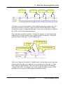
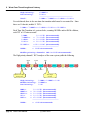
The eTPU is an event response machine. An event occurs and the eTPU executes a
thread that handles that event. The thread ends and the eTPU’s microsequencer goes idle
awaiting the next event on any of the 32-channels. Later, another event occurs and
another event-handling thread responds. This pattern repeats itself, event-then-thread,
event-then-thread, event-then-thread, ad infinitum. This pattern is shown below for a
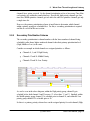
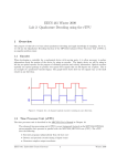
PWM.
Event
(Falling Edge)
Event
(Falling Edge)
Event
(Falling Edge)
Event
(Falling Edge)
Thread
Thread
Thread
Thread
In the picture shown above, the falling PWM pin is the event that triggers the thread.
Thread activity is shown in the waveform named ‘PwmThreads’ which is seen below the
PWM’s pin signal. The ‘PwmThreads’ signal is active high such that when it is a ‘1’ a
thread servicing the PWM channel is executing. When ‘PwmThreads’ is a ‘0’, the
eTPU’s microsequencer is either idle, or is executing a thread for another channel. The
thread closely follows the falling edge event (in this example) because the microsequencer
is mostly idle. However, in a more typical scenario there are other events occurring in
other channels that require event-handling threads and therefore the microsequencer may
be busy when the falling edge on the PWM channel occurs. This results in varying delays
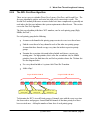
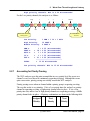
between the events and the event-handling threads, as shown below.
page 54, Toolk it User Manual
(C) 2007-2015
9. Worst Case Thread Length and Latency
Delay (latency)
Delay (latency)
Delay (latency)
Delay (latency)
The delays vary because the number of other channels requesting servicing varies. For
instance the first delay seen above is quite a bit shorter then the other delays, and the
second delay is quite a bit longer than the others. In fact, the second delay is so long that
the PWM is in risk of not functioning properly.
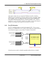
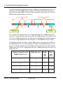
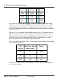
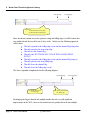
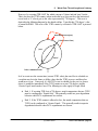
Why is the delay potentially a problem? Consider the sequence of events shown in the
diagram below. It begins with the event (1) which results in the thread (2). The thread
generates both the rising edge (3) and the falling edge (4).
3- Next Rising Edge
2- Thread
1- Event (Falling Edge)
4- Next Falling Edge
In the above diagram, if the thread (2) should become so delayed that it occurs later than
when the next rising edge (3) is supposed to occur, then the next rising edge (3) will be
either delayed or missed entirely. The exact behavior depends on how the channel is
configured (this will be covered later) but for now assume that neither scenario (PWM
operation ceases or lag in the PWM signal) is particularly desirable.
(C) 2007-2015
Toolk it User Manual, page 55
9. Worst Case Thread Length and Latency
9.2
Calculating ‘Worst Case Latency’
There is good news and bad news.
The good news is that for a particular system it is possible to do a static analysis to
determine the actual worst case latency. This can be compared to the required worst case
latency to see whether or not the system will function properly.
The bad news is that for (say) a PWM it is not possible to determine WCL without
knowing what else is in the system such as what other functions are running and what the
priority is assigned for those channels. In other words, PWM operation on a given channel
is dependent on what functions are operating on other channels, and also on how the
channels are configured (mode, scheduling priority, etc.)
Consider the following example in which two channels are active, ‘PWM’ and ‘TIMER’.
In this example the person who wrote the ‘TIMER’ function stayed up all night playing
video games and as a result could not focus at work and did a poor job writing the TIMER
function. In the following example the second timer thread is so long and occurs at such a
time that the PWM thread is delayed, thereby resulting in a shortened pulse.
Delayed Thread; WCL Requirement not Met
Long ‘TIMER’ Thread
9.2.1
Shortened Pulse
Second Long ‘TIMER’ Thread Causing a Problem
Worst Case Latency Definition
Worst Case Latency is defined as follows.
Worst case delay from an event to the end of the thread that handles the event.
An example of WCL is seen below.
page 56, Toolk it User Manual
(C) 2007-2015
9. Worst Case Thread Length and Latency
1- Event
2- Thread Ends
In this simple example at the exact moment the PWM thread would be scheduled, a
TIMER thread gets scheduled first such that the PWM thread must wait until the TIMER
thread completes. There is an additional short delay between when the TIMER thread
ends and the PWM thread begins known as a ‘Time Slot Transition’ or TST. The TST
typically lasts 6 system clocks and is required by the scheduler to decide which channel to
schedule for servicing next and to prepare the next thread for execution.
9.2.2
The eTPU Scheduler
The eTPU scheduling algorithm is a critical in determining the WCL. The core issue is
that there are 32 channels in the eTPU, yet there is only a single micro-sequencer that can
execute threads in response to events on those 32 channels, as shown below.
Host Service Request
Link Service Request
Match Event
Transition Event
Channel 0
Service Request
Channel T
Channel U
Channel V
Host Service Request
Link Service Request
Match Event
Transition Event
SCHEDULER
(USES PRIORITY SCHEME)
Channel 31
Service Request
Channel to be serviced next
So threads must necessarily be scheduled sequentially and threads that are scheduled
(C) 2007-2015
Toolk it User Manual, page 57
9. Worst Case Thread Length and Latency
earlier will have reduced latency while threads scheduled later will have increased latency.
9.2.3
Primary Priority Scheme
The eTPU has 32 channels and each of these channels is assigned a priority; High, Middle,
Low, or Off. The primary prioritization scheme is based on this assigned priority. Threads
are scheduled based on the following repeating seven ‘Time Slot’ pattern.
H-M-H-L-H-M-H
In other words, if many channels are requesting servicing all at once, a High priority
channel will get serviced first, followed by a Middle, then another High, then a Low, and so
forth.
Consider an example in which channels are assigned priorities as follows.
Channels 0..9 High Priority
Channels 10..19: Middle Priority
Channels 20..31: Low Priority
When all 32-channel request servicing simultaneously, the channels channel servicing is
shown below. Note that signal High_0_9 represents any High-Priority thread executing
and that a high priority has been assigned to channels 0 through 9. Similarly, signal
Middle_10_19 represents a thread on any of the Middle priority channels 10 through 19.
Signal Low_20_31 represents a thread on any of the Low priority channels 20 though 31.
Loop1: H-M-H-L-H-M-H
H
H
H
Loop2: H-M-H-L-H-M-H
H
M
M
H
H
H
H
H
M
M
L
L
As can be seen in the above diagram, some Middle and Low priority channels do get
scheduled before some High priority channels so what exactly does the priority level
mean? Notice that at the end of the second loop, eight High priority channels have gotten
serviced, four Middle priority channels have gotten serviced and only two Low priority
page 58, Toolk it User Manual
(C) 2007-2015
9. Worst Case Thread Length and Latency
channels have gotten serviced. So the channel prioritization refers to how many Time Slots
each priority gets within the round robin loop. Specifically, high priority channels get four
time slots, Middle priorities channels get two time slots and Low priorities channels get only
a single time slot.
However, the primary prioritization scheme is insufficient to determine which channel
within a priority group gets scheduled first. For this, a secondary prioritization is required
and this is covered in the next section.
9.2.4
Secondary Prioritization Scheme
The secondary prioritization is channel number with the lower numbered channel being
scheduled earlier than a higher numbered channel when their primary prioritization level
(High, Middle or Low) is the same.
Consider an example in which channels are assigned priorities as follows.
Channels 0, 1, and 2: High Priority
Channels 13 and 14: Middle Priority
Channels 25 and 26: Low Priority
H
H
H
M
M
L
L
As can be seen in the above diagram, within the High priority group, channel 0 gets
schedule before both channel 1 and 2 because ‘0’ is less than ‘1’ and ‘2. Similarly, within
the Middle priority group, channel 13 is schedule prior to channel 14, and within the Low
priority group channel 25 is schedule prior to 26.
So there is a primary priority scheme base on the assigned priority for each channel (High,
(C) 2007-2015
Toolk it User Manual, page 59
9. Worst Case Thread Length and Latency
Middle, and Low) and a secondary priority scheme based on channel number (Lower
channel number goes before higher channel number) but this leaves one significant issue to
be addressed.
9.2.5
Tertiary Priority Scheme
With the primary and secondary priority schemes there is a significant problem and it is
this. Consider the following situation.
Channels 0, 1, and 2 are all High priority (same priority group)
Channels 0, 1, and 2 all request servicing at once
Channel 0 constantly requests servicing, even after being serviced
With only the primary and secondary servicing scheme, since all the channels are in the
same priority group and channel 0 is the lowest numbered channel, it would get serviced
constantly and the other two channels would never gets serviced.
However, the Tertiary priority scheme solves this problem by only allowing a channel to
get serviced a second time when all the other channels that are requesting servicing within
a priority grouping have been serviced once. This is illustrated below.
Channel 0 requests servicing again
Channels 1 and 2 now serviced,
so Channel 0 can be serviced a second time
As seen in the above diagram, the tertiary priory scheme prevents channel 0 from getting
serviced a second time until both channels 1 and 2 have been serviced. This prevents
lockout on channels 1 and 2.
Note that the Tertiary priority scheme only acts on channels within a priority grouping.
page 60, Toolk it User Manual
(C) 2007-2015
9. Worst Case Thread Length and Latency
9.2.6
The WCL First-Pass Algorithm
There are two ways to calculate Worst Case Latency; First Pass, and Second Pass. The
first pass algorithm is quicker and easier but yields overly conservative results. The
Second Pass method yields more accurate results but is more complicated so generally not
used unless the first pass indicates that system requirements will not be met. This section
covers the First Pass algorithm
The first pass algorithm yields three WCL numbers, one for each priority group (High,
Middle, and Low.)
For each priority group do the following
Assume each channel in the priority group executes its worst case thread once.
Find the worst thread of any channel in each of the other two priority groups.
Assume that these threads occupy every time slot in their respective priority
groups.
Examine the seven-time-slot round robin schedule and choose a worst-case
starting point. For high priorities, this is after the second time slot, for Middle
priorities choose the third time slot, and for low priorities choose the 5’th time slot.
See the diagram below
For every thread include a 6-system-clock Time Slot Transition.
Add it all up!
Loop1: H-M-H-L-H-M-H
High
Middle
Worst Case ‘High’
Starting Point
High
Low
High
Worst Case ‘Middle’
Starting Point
Loop2: H-M-H-L-H-M-H
Middle
High
High
Middle
High
Low
High
Middle
High
Worst Case ‘Low’
Starting Point
To determine the WCL at each Priority group of channels, start with the worst-case time
slot shown above and progress forward until all channels of that time priority level have
been serviced once. Add up the number of time slots of each priority group.
(C) 2007-2015
Toolk it User Manual, page 61
9. Worst Case Thread Length and Latency
Let’s take an example in which there are three channels at the Middle priority level. Let’s
calculate the WCL for Middle priority channels. The diagram below shows how many
time-slots at the High, Middle, and Low priority levels get serviced (worst case) for each
Middle priority channel getting serviced once.
Loop1: H-M-H-L-H-M-H
1H
High
Middle
High
Loop2: H-M-H-L-H-M-H
2H
Low
1L
High
Middle
3H
4H
5H
High
High
1M
Middle
High
2M
6H
Low
High
2L
Middle
High
3M
Worst Case ‘Middle’
Starting Point
Third ‘Middle’
Serviced
As seen in the above diagram, there are 6 High priority time slots, 3 Middle priority time
slots, and 2 Low priority time slots between when the Middle channel seen to the left of the
‘Worst Case Middle Starting Point’ and when that same Middle priority channel completes
its second servicing indicated in the above diagram as ‘Third Middle Serviced’ channel.
The following table lists the number of High, Middle, and Low time slots that contribute to
the Middle priority WCL for various numbers of channels at the Middle priority level. For
instance, if only one channel is set to the Middle priority level, the first row shows that the
Middle priority WCL is has 2 High priority time slots, 1 Middle priority time slot, and 1 Low
priority time slot.
Number of channels at the
‘Middle’ Priority level
‘High’ time slots
‘Middle’
time
slots
‘Low’
time
slots
1
2
1
1
2
4
2
1
3
6
3
2
4
8
4
2
page 62, Toolk it User Manual
(C) 2007-2015
9. Worst Case Thread Length and Latency
Continuing with the previous example, take a system with four eTPU Functions, PWM,
UART, IC, and GPIO. The Worst Case Thread Length (WCTL) for each of these
channels is listed in the following table, as is how many of each function is running at each
priority level.
eTPU Function
Worst Case Thread
(microseconds)
‘High’ ‘Middle’ ‘Low’
priority priority priority
channels channels channels
PWM
0.30
1
1
1
UART
0.60
1
1
0
IC
1.32
0
0
1
GPIO
0.20
1
1
1
To calculate WCL for the Middle Priority channels, begin with the Middle priority
channels. There are three active channels, running PWM, IC, and GPIO. Each of these
channels executes its worst case thread once.
Next, find the worst case thread of any High priority channel. As seen in the above
diagram, this is the UART, so the worst case is the UART running threads continuously.
Finally, find the worst case thread of any Low priority channel. This is IC, and the worst
case is when this worst case thread is requesting servicing continuously. See below for
this worst case sequence.
1 UART
High
Middle UART
2
IC
3
UART
1 IC
PWM
4
UART UART
1 PWM
5
UART
1 UART
UART
6 UART’s
IC
2 IC’s
Worst Case ‘Middle’
Starting Point
UART
DIO
High
1 PWM
Third ‘Middle’
Serviced
Now, it is just a matter of adding everything up, see below.
Middle Priority:
1 PWM + 1 UART + 1 GPIO
(C) 2007-2015
Toolk it User Manual, page 63
9. Worst Case Thread Length and Latency
High Priority:
Low Priority:
6 UART’s
2 IC’s
--------------------------------1 PWM + 7 UART’s + 1 GPIO + 2 IC’s
Total:
For each thread, there is also one time-slot transition which must be accounted for. Since
there are 11 threads, include 11 TST’s.
1 PWM + 7 UART’s + 1 GPIO + 2 IC’s + 11 TST’s
Each Time Slot Transition is 6 system clocks, assuming 100 MHz and no RAM collisions,
each TST is 0.12 microseconds.
1
7
1
2
11
PWM:
UART’s:
GPIO:
IC’s:
TST’s:
1 * 0.32 (microseconds)
+ 7 * 0.60 (microseconds)
+ 1 * 0.20 (microseconds)
+ 2 * 1.32 (microseconds)
+ 11 * 0.06 (microseconds)
-------------------------= 8.02 microseconds
TOTAL:
Middle priority channels’ WCL is 8.02 microseconds!
The High priority channels’ WCL analyses of the same system yields the following.
1 PWM
High
UART
1 UART
PWM
1 UART
IC
UART
1 IC
Worst Case ‘High’
Starting Point
TOTAL:
page 64, Toolk it User Manual
UART
DIO
High
Middle
High
2 UART’s
Third ‘High’
Serviced
High Priority:
Middle Priority:
Low Priority:
PWM’s:
UART’s:
GPIO’s:
IC’s:
TST’s:
1 DIO
+
+
+
+
1 PWM + 1 UART + 1 IC
2 UART’s
1 IC
1 * 0.32 (microseconds)
3 * 0.60 (microseconds)
1 * 0.20 (microseconds)
1 * 1.32 (microseconds)
6 * 0.06 (microseconds)
-------------------------= 4.00 microseconds
(C) 2007-2015
Low
High
Middle
High
9. Worst Case Thread Length and Latency
High priority channels’ WCL is 4.00 microseconds!
For the Low priority channels, the analysiss is as follows:
1 High
High
Middle
High
2
Low
High
1 Low
Middle
3
4
High
High
1 Middle
5
Middle
High
2
6 High’s
Low
2 Low’s
Worst Case ‘Middle’
Starting Point
TOTAL:
Middle
High
3 Middle’s
Third ‘Middle’
Serviced
Low Priority:
High Priority:
Middle Priority:
PWM’s:
UART’s:
GPIO’s:
IC’s:
TST’s:
High
+
+
+
+
1 PWM + 1 IC + 1 GPIO
12 UART’s
6 UART’s
1 * 0.32 (microseconds)
18 * 0.60 (microseconds)
1 * 0.20 (microseconds)
1 * 1.32 (microseconds)
21 * 0.06 (microseconds)
-------------------------= 13.90 microseconds
Low priority channels’ WCL is 13.90 microseconds!
9.2.7
Accounting for Priority Passing
The WCL analyses up to this point assumed that in every priority level, the worst case
channel’s worst case thread is continuously requesting servicing. Although this seems
quite conservative, priority passing can actually worsen this WCL analyses.
Priority passing occurs when no channel within a priority group is requesting servicing.
The way this works is very intuitive. If it is a Low priority time slot, and no Low priority
channel is requesting servicing, a High priority channel takes its place. If it is a Low
priority time slot, and no Low or High priority channels are requesting servicing, a Middle
priority channel takes its place. All priority combinations are shown in the following table.
Assigned
Priority
Next
Priority
(C) 2007-2015
Next
Priority
Toolk it User Manual, page 65
9. Worst Case Thread Length and Latency
Level
Level
Level
High
-->
Middle
-->
Low
Middle
-->
High
-->
Low
Low
-->
High
--> Middle
So how does this affect the WCL analyses? If the WCL analyses is for Middle priority,
and there is a time slot in which no Middle priority channel is requesting service, then the
original Middle priority channel that is requesting service gets serviced sooner, so this has
the affect of reducing (improving) latency and therefore the affect need not be considered
for the worst-case.
However, if WCL is being done on the Middle priority, and it is a Low priorities time slot,
and no Low priority channels are requesting service, then the Time Slot may be given to a
High priority channel. If the worst-case High priority thread is longer than the worst-case
Low priority thread, then the Middle priority WCL must assume that the Low priority
threads are priority-passed to the (longer) High-priority thread.
It is easy to generate an example of this. Assume that the system consists of the following
three channels and priorities.
eTPU
Function
Worst Case Thread
(microseconds)
Priority
PWM
0.30
Middle
UART
0.60
High
GPIO
0.20
Low
For this system with just three channels running per the above table, the following shows
the worst-case sequence.
page 66, Toolk it User Manual
(C) 2007-2015
9. Worst Case Thread Length and Latency
Which is worse?
The assigned Low priority DIO thread (0.2 microseconds)
Or a priority-pass to a High priority UART thread (0.6 microseconds?)
High
Middle UART Low UART
DIO
Worst Case ‘Middle’
Starting Point
High
‘Middle’
Serviced
So by priority passing, in this simple case with only three active channels (one at each
priority level) the middle priority WCL increases due to priority passing from the (shorter)
low-priority time slot thread to the longer high-priority time-slot thread.
A similar worsening of the WCL for the Low channels occurs when there is priority
passing from a (shorter) Middle priority thread to a (longer) high priority thread.
However, there is no affect on the High priority WCL calculation because any Low or
Middle priority time slot would priority-pass to a High priority thread, thereby reducing the
overall latency.
9.2.8
RAM Collisions and Ram Collision Rate (RCR)
RAM collisions occur when the eTPU and the host CPU access the parameter RAM at
the same time. When such a RAM collision occurs, the eTPU may need to wait for the
eTPU. Well written CPU code should access the eTPU RAM infrequently, and should
never (say) poll the eTPU because this can result in high RCR’s.
A detailed examination of the RCR is beyond the scope of this manual. However,
considering that in typical eTPU code less than 20% of instructions access the RAM, and
that a typical RCR is well under 10%, adding a couple percent of ‘fudge factor’ to the
WCL’s is generally all that is required to account for RAM collisions.
A scenario where the 2-percent ‘fudge factor’ approach fails is when the number of
(C) 2007-2015
Toolk it User Manual, page 67
9. Worst Case Thread Length and Latency
instructions comprising the WCL is low, say under 50, such that there are (say) only 10
RAM accesses. With this very small number of RAM accesses, a more detailed
accounting of RAM collisions on WCL may be required.
When accounting for RAM collisions it is also important to include the two RAM accesses
that occur during the Time Slot Transitions. These eTPU RAM accesses can collide with
the CPU’s accesses and can delay the eTPU.
9.2.9
Second Pass Analyses
A second pass analyses involves incorporating system-specific information into the
equation. This generally yields WCL’s that reduced by half, which is a surprisingly-large
but somewhat consistent amount.
Take the case where the worst-case thread in the priority group not being analyzed is a
PWM. The first-case assumption is that this thread will occupy every single time slot.
However, if the PWM alternates between rising and falling edge handling threads, and
these two threads are not of equal length, then the WCL analyses will show an improved
WCL if this information is included in the equation. Similarly if the PWM’s minimum
period is (say) 50 microseconds, then using this information may be able to reduce the
calculated WCL even further.
9.3
Worst Case Thread Length (WCTL)
The worst-case thread length (WCTL) for each eTPU function is required in order to
calculate Worst Case Latency (WCL.) This data can be acquired in either the Simulator
or the ETEC Compiler as described in the following sections.
9.3.1
Naming Threads in Legacy (eTPUC) Mode
In the legacy eTPU mode a thread is within a scope-block formed by an if/else array.
These scope blocks form threads and are automatically assigned names by the compiler.
However, it is possible to override the compiler-assigned names by adding ‘dummy’ labels.
These dummy labels must appear immediately following the if/else curly-bracket, as shown
below.
else if ( IsMatchBOrTransitionAEvent() )
{
PWM_handle_falling_edge_thread:
page 68, Toolk it User Manual
(C) 2007-2015
9. Worst Case Thread Length and Latency
// ertB contains the TCR1 count of the falling edge
LastFallingEdge = ertB;
// Calculate the time for the next falling edge
NextFallingEdge = LastFallingEdge + Period;
ertB = NextFallingEdge;
// Calculate the time for the next rising edge
NextRisingEdge = NextFallingEdge - HighTime;
// ertB contains the TCR1 count of the falling edge
ertA = NextRisingEdge;
// ertA and ertB contain
// the next rising & falling edge times
// Write these times out to the channel hardware
// and generate the next set of rising & falling edges
// by generating match events
ClearMatchAEvent();
ClearMatchBEvent();
WriteErtAToMatchAAndEnable();
WriteErtBToMatchBAndEnable();
}
In the above example the thread that handles the PWM’s falling edge event is named,
‘PWM_handle_falling_edge_thread.’
Note that in ETEC mode, the threads are within functions of type _eTPU_thread, so the
thread name is simply the function name. In the ETEC assembler the thread name is
simply the entry label.
Having a user assigned thread-name is important because #pragma verify_wctl requires a
thread name. Additionally, features with thread references within the simulator (such as
the ThreadStats windows) use these thread names.
9.3.2
Viewing WCTL in the Simulator
The simulator’s ThreadStats window is used to view information w/r to thread length. This
is accessed from the ‘View’ menu by selecting the ‘Threads’ sub-menu. The ThreadStats
window shown at the bottom of the following picture becomes visible.
(C) 2007-2015
Toolk it User Manual, page 69
9. Worst Case Thread Length and Latency
However, the ThreadStats window requires further specification in order to have it display
the desired channel (or all channels set to a particular eTPU Function.) Move the mouse
into the ThreadStats window and click the right mouse botton. From there a particular
channel can be specified, or all channels set to a particular eTPU Function.
If there is no thread-name displayed on the right side of the ThreadStats window, see
Section Error! Reference source not found., “Error! Reference source not found..”
Another useful feature is to place the mouse above a particular thread and click the left
mouse button. This highlights the first line of source code associated with that function. In
the above diagram, the PWM_init thread has been selected, and in the source code
window the PWM_init thread is highlighted.
This ThreadStats window displays the number of instruction steps (both total and in the
worst-recorded thread) for that thread. The number of RAM accesses is also displayed,
though this is the number of RAM accesses in the longest-recorded thread.
However, there is one significant drawback to the simulator’s ThreadStats window. It
records as the Worst Case, only the worst ENCOUNTERED case. So if in your tests the
worst thread has not been executed, the ThreadStats window will display an invalid and
too-short thread as the worst case.
In the next two sections it can be seen how the true worst case thread is both viewable
and tested using a #pragma verify_wctl construct.
page 70, Toolk it User Manual
(C) 2007-2015
9. Worst Case Thread Length and Latency
9.3.3
Viewing WCTL in the Compiler
The ETEC compiler performs a static analysis of the WCTL for every thread. The results
are displayed in the analysis file as shown below. This is pulled from Freescale’s Set1
functions. Note that the analyses file name is the same as the output ELF/DWARF file
(unless overridden or disabled) except that the file suffix (.ELF) is replaced with ‘_ana.
html’.
A number of notable things are seen in the WCTL section of the analyses file shown
above.
First, the worst case thread (PWM_frame_edge_active_low) is highlighted because it is
the worst case thread. This PWM_frame_edge_active_low has 15 instruction steps and 6
RAM accesses. RAM accesses are interesting (but generally not significant) because if
the host-CPU and the eTPU access the RAM at the same time, it can cause a collision
which may delay the eTPU’s microsequencer by two system clocks.
Another interesting feature is seen in the PWM_undefined thread. It is listed as
(C) 2007-2015
Toolk it User Manual, page 71
9. Worst Case Thread Length and Latency
‘Excluded’ because this thread should never execute. This ‘PWM_undefined’ thread
responds to invalid events that never occur for example a ‘link’ event. For reliability
purposes, the thread that executes is in the error handler library.
How does ETEC know that this thread never executes? The user tells ETEC by adding a
#pragma exclude_wctl construct with the thread-to-be excluded name anywhere in the
source code, as follows for the ‘PWM_undefined’ thread.
#pragma exclude_wctl PWM_undefined
9.3.4
Enforcing that WCTL Requirements are met
The importance of WCTL as a contributor to WCL has been examined, as has
mechanisms for determining the WCTL for each eTPU Function in the Simulator and
ETEC compiler. However, to achieve a more maintainable and higher-quality solution, the
WCTL enforcement mechanism should be used.
Take an example where you have inherited an eTPU Function. Say the original engineer
knew that in order to function properly in the system a WCTL of (say) no more than 3
steps (instructions) is required. Perhaps that engineer monitored that this requirement is
being met by examining the analyses file on every build.
However, maybe that engineer is now working for some other company and perhaps the
requirement was not passed on to you so you do not know to monitor the analyses file. So
when your boss asks you to add an enhancement, and that enhancement causes the
WCTL requirement to be exceeded, you have unknowingly broken the eTPU Function.
The verify_wctl construct provides a mechanism for embedding WCTL requirements
directly into the source code. The construct does this by verifying that a user-specified
maximum number of steps (instructions) is not exceeded. If the limit is exceeded the build
fails. One form of this construct is shown below.
#pragma verify_wctl <eTpuFunction> <NumSteps> steps <NumRams> rams
For example to verify that the PWM function’s worst case thread does not exceed 3 steps
(instructions), use the following construct.
#pragma verify_wctl Pwm 3 steps 5 rams
It is often desireable to verify that a specific thread within and eTPU Function does not
exceed some limit. For example a thread named 'RisingEdgeThread' can be verified as
follows.
#pragma verify_wctl Pwm::RisingEdgeThread 2 steps 3 rams
If this PWM requirement is not met, the build will fail, as shown below
page 72, Toolk it User Manual
(C) 2007-2015
9. Worst Case Thread Length and Latency
LINK ERROR [82542] file "Pwm.c" line 11:
Maximum thread length exceeded
Allowed WC Steps:
3
Actual WC Steps:
6
Allowed WC RAM's:
5
Actual WC RAM's:
0
File "Pwm.c" line 18
#pragma verify_wctl Pwm Failure
This way, you can detect a failure to meet WCTL requirements as early as possible in the
development cycle.
Other forms of this construct can verify the WCTL of a specific entry table (in ETEC
mode a single eTPU Function (Class) can have multiple associated entry tables.) See the
ETEC Reference Manual for more information.
9.4
Improving WCL Degradation Mode
In a perfect world, WCL requirements are always met. However, in many cases WCL
requirements are not met and in fact, there are many successful eTPU designs in
production today in which these requirements are not met.
The key is to design defensively such that when WCL latency requirements are not met
the degradation mode is benign. This section covers strategies for reducing WCL
requirements and for designing defensively such that when WCL requirements are not met,
the degradation mode is as benign as possible.
9.4.1
Use the Greater/Equals Time Base
Each action unit in the channel hardware contains a match comparator which is configured
to be either ‘equals only’ or ‘greater equals.’ For output eTPU Functions such as a PWM,
the match comparator is typically fed into output pin logic which toggles the output pin on a
MATCH, as shown below.
(C) 2007-2015
Toolk it User Manual, page 73
9. Worst Case Thread Length and Latency
TimeBase();
TCR1 or TCR2
+Match
Comparator
“==“ or “>=“
MATCH Reg
_
Output Pin
Action Logic
The Match Comparator
Consider the following sequence of events.
The free-running TCR1 counter is at 20
The MATCH register is written to 25
The TCR1 counter is free running, so it goes 21, 22, 23, 24, 25
When the TCR1 counter hits 25, the MATCH Comparator fires
Firing of the MATCH Comparator triggers a rising edge on the channel’s output
pin
The above sequence of events occurs when WCL requirements are being met because the
starting TCR1 counter value (20) is less than the value written to the MATCH register
(25.) But what happens if there is a delay such that when the section of code that writes a
25 to the MATCH register executes, the TCR1 counter is already greater than 25, say it is
at 30 instead. What happens, will a rising edge be triggered on the output pin?
Well, that depends on whether the MATCH comparator has been configured as ‘Equals
Only’ or as ‘Greater or Equals’ mode.
If the MATCH comparator has been programmed via the TBS field to be ‘Greater or
Equals’ then the output rising edge will still be triggered, but it will be 5 TCR1 (or TCR2)
increments too late. Depending on how TCR1 is configured, this may be 0.1
microseconds, for many systems this may not be a huge deal. This degraded mode when
WCL is not met is seen in the following diagram.
page 74, Toolk it User Manual
(C) 2007-2015
9. Worst Case Thread Length and Latency
Delayed Thread; WCL Requirement not Met
Long ‘TIMER’ Thread
Shortened Pulse
Second Long ‘TIMER’ Thread Causing a Problem
However, if the MATCH comparator has been configured in ‘Equals Only’ mode then the
TCR1 (or TCR2) counter must complete a full cycle and return to 20 before the output
pin’s rising edge is triggered. If the MATCH is triggered off a free-running TCR1 counter,
the best case rollover is around 250 milliseconds, which is an electronic eternity.
So although every application has its own specific set of requirements, it is generally best to
configure the MATCH comparator to use the ‘Greater or Equals’ mode.
9.4.2
Post-Check an ‘Equals Only’ Match
Suppose that system requirements dictate use of the ‘Equals Only’ Time Base mode. All
is not lost if WCL requirements are not always met. One strategy is to check the value
written into the MATCH register against the TCR1 counter, as shown below. Note that
the use of the ATOMIC region assures that the TCR1 counter value at the exact time that
the match is written in used in the comparison.
// Record the TCR1 value at which the match is generated
// 'Atomic' assures that it all goes in the same instruction
#pragma atomic_begin
int l_savedTcr1 = tcr1;
ClearMatchAEvent();
WriteErtAToMatchAAndEnable();
ClearMatchBEvent();
WriteErtBToMatchBAndEnable();
#pragma atomic_end
if( l_savedTcr1 – ertA >= 0 )
{
// An equals-only match was missed
// Trigger a link-to-self event
// The link-thread will handle the
// missed match situation
link = chan;
(C) 2007-2015
Toolk it User Manual, page 75
9. Worst Case Thread Length and Latency
}.
The overall strategy is to detect a missed match by triggering a link thread that takes some
palliative action in the link-handling thread.
9.4.3
Break Big Threads into Multiple Smaller Threads
In the vast majority of systems the WCL for a particular channel is not determined by
WCTL of the eTPU Function running in that channel, but rather by the WCTL of all the
other threads running in all the other channels. Consider the WCL of the Middle priority
channels in the following example in which three channels are set to the Middle priority.
1 High
High
Middle
High
2
Low
1 Low
High
Middle
3
4
High
High
1 Middle
5
Middle
2
High
6 High’s
Low
2 Low’s
Worst Case ‘Middle’
Starting Point
High
Middle
High
3 Middle’s
Third ‘Middle’
Serviced
In the above example, the WCL contributors are 6 High priority time slots, 2 Low priority
time slots, and 3 middle priority time slots for a total of 11 time slots. The Time slot of
each Middle priority channel represents just 1/11 of all the time slots that contribute it its
WCL.
So over 10/11 of the time slots (over 90%) are belong to other channels of any particular
Middle priority channel.
Therefore, the key to achieving a low WCL on the Middle priority channels is to keep the
WCTL of the worst case High and Low priority channels as low as possible. And the
same goes for the High priority WCL which is determined largely by the Middle and Low
priority WCTLs. Similarly, the Low priority WCL is largely determined by the Middle and
Low WCTLs.
Consider the Middle priority WCL in the following system which contains one Middle
priority UART and two Middle priority GPIO’s, and the rest of the channels are a mix of
PWMs set to High and Low priorities.
eTPU
page 76, Toolk it User Manual
Worst Case Thread
‘High’
(C) 2007-2015
‘Middle’
‘Low’
9. Worst Case Thread Length and Latency
Function
(microseconds)
priority priority priority
channels channels channels
PWM
0.30
14
0
14
UART
0.60
0
1
0
GPIO
0.20
0
2
0
The Middle priority WCL calculation comes out as follows.
PWM’s:
UART’s:
GPIO’s:
TST’s:
+
+
+
TOTAL:
8 * 0.30 (microseconds)
1 * 0.60 (microseconds)
2 * 0.20 (microseconds)
11 * 0.06 (microseconds)
-------------------------= 4.06 microseconds
Now, let’s assume that the PWM’s 0.3 microsecond WCTL can be nearly halved by
splitting it into two smaller threads, each of which is 0.16 microseconds. By splitting the
PWM’s worst-case thread the number of time slots in the Middle priority WCL calculation
does not change. So the WCL calculation changes as follows.
PWM’s:
UART’s:
GPIO’s:
TST’s:
TOTAL:
+
+
+
8 * 0.16 (microseconds)
1 * 0.60 (microseconds)
2 * 0.20 (microseconds)
11 * 0.06 (microseconds)
-------------------------= 2.94 microseconds (>25% reduction)
Therefore, reducing WCL by breaking large threads up into smaller threads can yield
significant improvements. However, opportunities for breaking up long threads into shorter
threads must be determined on a case by case basis. For the PWM in this example the
thread is performing two tasks; each thread is calculating both the rising and falling edge
time, as seen below.
(C) 2007-2015
Toolk it User Manual, page 77
9. Worst Case Thread Length and Latency
(1) Rising Edge
(2) Falling Edge
This thread:
(1) Generates PWM’s rising edge
(2) Generates PWM’s falling edge
Since the thread contains two tasks (generate rising and falling edges) it will be broken into
two smaller threads that each do one of these tasks. In this case the following approach
will be taken.
Thread1 responds to the falling edge event and the channel flag being clear
Thread1 generates the next rising edge
Thread1 sets the channel flag
Thread1 ends, BUT DOES NOT CLEAR THE FALLING EDGE
EVENT!
Thread2 responds to the falling edge event and the channel flag being set
Thread2 generates the next falling edge
Thread2 clears the channel flag
Thread2 clears the falling edge event!
The above algorithm is implemented in the following diagram
Next Rising Edge
This thread generates the
next rising edge
Next Falling Edge
This thread generates the
next falling edge
Breaking up the biggest threads into multiple smaller threads can yield significant
improvements in the WCL, however the method used to partition the tasks into multiple
page 78, Toolk it User Manual
(C) 2007-2015
9. Worst Case Thread Length and Latency
threads varies from one application to the next.
9.4.4
Reduce WCL through Thread Balancing
This method of reducing WCL is similar to the ‘break big threads into multiple smaller
threads’ except that the tasks are re-partitioned within existing threads instead of moved
into new threads. For instance suppose that the tasks are partitioned as follows
Thread 1 Tasks:
o Task A: 0.3 microseconds
o Task B: 0.5 microseconds
Thread 2 Tasks:
o Task C: 1.7 microseconds
o Task D: 1.4 microseconds
So with the portioning shown above Thread 1 tasks total 0.8 microseconds and the WCTL
is from Thread 2 which totals 3.2 microseconds.
Suppose instead the thread tasks are load balanced as follows.
Thread 1 Tasks:
o Task A 0.3 microseconds
o Task C 1.7 microseconds
Thread 2 Tasks:
o Task B: 0.5 microseconds
o Task D: 1.4 microseconds
By repartitioning the tasks, the two threads are now 2.0 microseconds and 1.9
microseconds, thereby reducing this eTPU Functions WCTL from 3.2 microseconds to 2.0
microseconds, a 37% reduction.
(C) 2007-2015
Toolk it User Manual, page 79
9. Worst Case Thread Length and Latency
9.4.5
Reduce WCL Requirements through Thread Architecture
Consider again the following PWM function.
Next Rising Edge
This thread generates the
next rising edge
Next Falling Edge
This thread generates the
next falling edge
The sequence events from the falling edge that generates the second thread is as follows.
Falling edge event
Thread that generates the ‘Next Falling Edge’
Falling edge
There is an entire period in which the second thread can occur because so the WCL must
be less than the period.
However, the WCL requirements are much worse for the thread that generates the ‘Next
Rising Edge’ due to the sequence of events shown below.
Falling edge event
Thread that generates the ‘Next Rising Edge’
Next Rising Edge
So the thread must occur between the falling and rising edges which results in the
requirement that the WCL be less than the low pulse width. This WCL requirement for
this Thread can be significantly reduced if the thread were triggered by the Rising edge
instead of the falling edge as follows
Rising edge event
Thread that generates the ‘Next Rising Edge’
Next Rising Edge
As seen in the following diagram, the threads that respond to the rising edge event respond
to generate the ‘Next Rising Edge’ and the thread that responds to the falling edge event
generates the next rising event. Although by architecting the threads this way the WCL
page 80, Toolk it User Manual
(C) 2007-2015
9. Worst Case Thread Length and Latency
does not change, the WCL requirement is significantly less rigid because in all cases the
WCL requirement is to less than every second edge or (in general) less than the period of
the PWM.
Authors note on implementing this design change. The channel mode was changed from
‘MatchBSingleTransition’ to EitherMatchNonBlockingSingleTransition. Channel flags are
still required to maintain proper thread sequencing in the case when both rising and falling
edge events are pending.
9.4.6
WCL Degradation in Angle Mode
It was shown earlier in this chapter that the WCL degradation mode is generally improved
when the match comparator is configured as ‘Greater Equal.’ This is because if WCL
requirement is exceeded the match still occurs, just a little late. On the other hand, when
the match comparator is configured as ‘Equals Only’ and the WCL requirement is not met,
the output may go idle for a long, long time.
Consider a free running TCR1 counter and a MATCH event scheduled for the future as
seen below. The circle represents the values traversed by the free-running TCR1 counter.
The boundary between ‘Future’ and ‘Past’ being the point on the exact opposite side of
the circle as the current TCR1 value.
(C) 2007-2015
Toolk it User Manual, page 81
9. Worst Case Thread Length and Latency
TCR1 (Current Time)
Next MATCH event (future)
"past"
"future"
TCR1 + 0x800000 counts
In the diagram shown above, the match event ‘works’ because it is scheduled for the
future, or specifically, greater than the current TCR1 counter value and less than the
current TCR1 counter value plus 0x800000. However, the TCR1 counter has limited
dynamic range and if the MATCH event were scheduled too far into the future it would be
in the past instead of the future. Specifically, the current TCR1 counter value plus
0x800000 represents the boundary between ‘future’ and ‘past’. Even at the TCR1
counters maximum rate, the ‘Future/Past’ boundary is still in the hundreds of milliseconds.
page 82, Toolk it User Manual
(C) 2007-2015
9. Worst Case Thread Length and Latency
However, by asserting TPR.LAST the whole concept of ‘future’and and ‘past’ breaks.
This is because the TCR2 counter (when used in this way) does not free run, but instead
resets back to ‘0’ after it gets to the value represented by ‘720 degrees’. This reset is
depicted in the following diagram by the dotted red line. Typically that ‘720 degree’ value
is around 0x2D000. This reset of the TCR2 counter by assertion of TPR.LAST is pictured
below.
Next MATCH event (past)
TCR1 (Current Time)
"past"
"future"
TCR1 + 0x800000 counts
So if an event uses the current time (current TCR2 value) plus an offset to schedule an
event that may be in the future at all the values that the TCR2 traverses and therefore
would never occur. Conversely, if a MATCH event is schedule for the past (as shown
above) it would fire immediately if the TCR2 counter was near 720 degrees and the
‘Greater Equal’ match mode is used. The following two rules apply for Angle Mode
Rule 1: If asserting TPR.Last at 720 degrees, match comparators that use TCR2
must be configured as ‘Equals Only.’ This generally results in a poor degradation
behavior when WCL requirements are not met.
Rule 2: If the TCR2 counter is allowed to free, the match comparators that use
TCR2 can be configured as ‘Greater Equals.’ This generally results in superior
degradation behavior when WCL requirements are not met.
(C) 2007-2015
Toolk it User Manual, page 83
page 84, Toolk it User Manual
10. Channel Instructions
10
Channel Instructions
Channel instructions are used to configure the channel hardware. Proper use and
especially ordering of channel instructions is critical to generation of efficient, optimal and
most importantly, robust eTPU code.
eTPU instruction set’s parallelism affords a huge optimization opportunity, especially with
respect to parallelizing channel instruction. For example a half dozen or more channel
instructions can often be fitted into a single instruction, yielding code size reduction of
certain code segments of 80% or more. Aggressive optimization techniques can yield code
size reductions of 50% or more in certain types of applications.
Unfortunately, there is a downside to aggressively parallelizing and reordering channel
instructions which is that behavior is often dependent on their execution order. For
example, clearing the Match Recognition Latch (MRL) and writing the Match Register can
have subtle, yet different behavior depending on whether the clear occurs first, the write
occurs first, or whether the two channel instructions occur in the same instruction. For this
reason the parallelization of the instruction set is both well defined in this manual, AND
most importantly, the user is given full control over both parallelization and re-ordering.
(C) 2007-2015
Toolk it User Manual, page 85
10. Channel Instructions
10.1
Link Service Requests
The link instruction does not interact with other channel instructions and therefore there are
no restrictions on reordering or parallelization.
There may be a cross channel Link Service Requests (LSR) timing dependency relative to
RAM loads or stores where the two eTPU engines are using links to do cross engine
synchronization. For instance an eTPU engine could write a variable to RAM, and then
link to a channel on the other engine, causing the other engine to execute a thread in which
the variable is read. Since it is critical that the Link Service Request occur no sooner than
when the variable is written (such that the other engine does not read the variable before it
is written) this timing dependency must be communicated to ETEC as follows.
SharedVar = 22;
#pragma synch_boundary_all;
link(other engine, 5);
10.2
Pre-Defined Channel Mode (PDCM)
Pre-defined channel mode (PDCM) is generally the first channel instruction that gets
executed at initialization. Once configured its setting is retained indefinitely, and reconfiguration is discouraged.
PDCM will be will be reordered relative to non-channel instructions (ALU, PRAM, etc)
and relative to the Flag Control (FLC,) Link Service Requests (LSR) Interrupts (CIRC and
DTR)
The PDCM instruction will not be re-ordered relative to all other channel instructions.
The PDCM will be joined together with a channel instruction that follows it where possible
to take advantage instruction set parallelism.
The PDCM will not be joined together with channel instructions found above this
instruction, though there is generally no optimization penalty for this restriction because the
PDCM write should generally be the first Channel Instruction in the initialization thread.
page 86, Toolk it User Manual
(C) 2007-2015
11. ALU/MDU Intrinsics
11
ALU/MDU Intrinsics
The eTPU hardware has capabilities not easily accessible through standard C syntax. A
set of intrinsics, defined in the standard header file ETpu_Lib.h, has been developed to
provide users access to these capabilities with C function-like calls (intrinsics). All
available intrinsics are described in the reference manual; the general categories are:
rotate right
absolute value
shift register
shift by 2(N+1)
set/clear bit
exchange bit
MAC/MDU
An example of the usefulness of such constructs can be found in the Freescale Set 1
stepper motor control function. An existing code snippet is:
/* rotate right by 1 bit */
pin_sequence >>= 1;
if (CC.C == 1)
{
(C) 2007-2015
Toolk it User Manual, page 87
11. ALU/MDU Intrinsics
pin_sequence += 0x800000;
}
This could instead be written much more efficiently with a rotate right intrinsic:
pin_sequence = __rotate_right_1(pin_sequence);
One important note with regards to MAC/MDU intrinsics. The code generated by these
intrinsics includes a MAC-busy loop. In other words, the user can access the macl/mach
registers right after such an intrinsic and expect that the result is there. The compiler/
optimizer will attempt to eliminate the MAC-busy loop by placing any MAC-independent
code in the pipeline, if possible.
11.1
Safe current input pin state sampling
This construct samples the current input pin state and coherently clears the transition
detection latches such that if the input pin state were to transition right as the pin state was
being set, the TDL being set by that transition would not get missed. Either the recorded
pin state would be from before the transition AND the TDL gets set again, or the recorded
pin state is from after the transition AND the TDL remains cleared.
The key point is that the channel register needs to be written in the exact same instruction
as the TDL latch gets cleared. This is accomplished in ETEC using the “atomic”
constructs. By use of this “atomic” region, the atomicity is not at the whim of the compiler
but rather explicitly controlled by the user.
void PPA_CheckPin()
{
/*-------------------------------------------------------------------+
| This re-writes the chan value and at the same time clears the
|
| transition latch (tdl).
|
| This causes the pin state to be latched.
|
| If the pin does not transition after it is latched, tdl will
|
| remain clear.
|
| If the pin changes state after it is latched, tdl will be set
|
| again, and processed
|
| after this thread quits.
|
| The design of the hardware ensures
|
| the pin state and value
|
| of tdl are coherent.
|
| tdl does not have to be checked in the current thread.
|
| It is the current (latched in this sub routine) and last pin levels|
| that determine
|
| the operation of the state machine
|
| The current pin level is obtained from channel.PSS
|
+----------------------------------------------------------------- -*/
page 88, Toolk it User Manual
(C) 2007-2015
11. ALU/MDU Intrinsics
_AtomicBegin();
ClearTransLatch();
chan = chan;
_AtomicEnd();
}
11.2
Changing the TPR.TICKS field
The TPR’s TICKS field is in the same register as the TPR.LAST, TPR.MSCNT, TPR.
IPH and TPR.HOLD fields, all of which need to be accessed atomically because both the
ALU and the Angle Hardware have write access to these fields. Consider the following
code sequence
Tpr.Ticks = 0x200;
From this, the ETEC compiler will generate the following opcode sequence.
Alu
Alu
Alu
Alu
a = 0xfc00;;
a = ToothProgram & a;;
a = a | 0x200;;
ToothPogram = a;;
Say between second and fourth opcodes, a physical tooth passes such that the angle
hardware clears a (previously set) TPR.LAST field. In this case, the fourth opcode will
set the TPR.LAST field, this is almost for sure NOT the desired behaviour!
Unfortunately there is no way to fix this problem (even using an assembler) because there
is no way to atomically write the TPR.TICKS field! Therefore it is incumbent on the user
to adopt a strategy that avoids this problem.
Your friendly ETEC code generation tools suite recommend one of the following two
strategies:
Only modify the TPR.TICKS field ONCE in the initialization routine.
Only modify the TPR.TICK field if TPR.LAST, TPR.MSCNT, TPR.IHP, and TPR.
HOLD fields are ALL at zero.
This latter strategy is effective because the angle hardware only clears the TPR.LAST,
TPR.MSCNT, TPR.IPH, and TPR.HOLD fields. Therefore, if those fields are already
cleared, then the angle hardware will not modify them, and a non-atomic strategy is not
problematic.
As a side note, if the TPR.IPH, TPR.HOLD, and TPR.MSCNT fields are all cleared, then
(C) 2007-2015
Toolk it User Manual, page 89
11. ALU/MDU Intrinsics
the following code generates both an identical result, and 4X tighter code.
TPR = 0x200
11.3
Enforcing Timing Dependencies
The eTPU instruction set is highly parallel and it is generally possible to fit two, three, a
half dozen, or more instructions into a single opcode. Code size reduction due to
optimizations that take advantage of the parallel nature of the instruction set can reduce
code size by 50% or more for most applications.
For this reason, ETEC aggressively optimizes using both parallelism and where appropriate,
performs reordering.
Unfortunately it not always possible for ETEC to identify all timing dependencies,
especially for RAM and Channel instructions. An example of such a timing dependency
might be a buffer in which the eTPU first writes a value into the buffer, and then writes
another value that indicates to the CPU that there is a new value in the buffer. It would
not be acceptable for ETEC to change the order of these (it would be unlikely to occur
anyways, the only reason it would is if it could somehow combine an 8 and 24 bit write into
one 32 bit write in such a way that it ends up re-ordering the writes). To ensure the
ordering remains as written, the user can explicitly place an optimization boundary between
the data writes, such as
#pragma optimization_boundary_all
11.3.1 Use ATOMIC regions
Quite a few constructs require atomic sub-instructions, especially channel sub-instructions.
The legacy (apparently) did not support guaranteed atomic regions, though the compiler
would generally generate correct code. As such quality was assured “by convention.”
The ETEC compiler adopts similar conventions established by the legacy compiler such
that atomic channel hardware operations should work the same, but to guarantee proper
operation a superior (and suggested) strategy is to use the atomic regions such that
operations that must be in the same instruction due to atomic requirements are guaranteed
to be atomic.
For example clearing the MRL latch and re-writing a match value should almost always be
done in the same instruction, as follows
page 90, Toolk it User Manual
(C) 2007-2015
11. ALU/MDU Intrinsics
_AtomicBegin();
EnableMatchA();
ClearMatchALatch();
_AtomicEnd();
Note that the standard macros available in the provided ETpu_Std.h make use of atomic
regions and are generally how users should access the channel hardware (e.g. see the
SetupMatchA macro).
11.4
Should not declare static variables in regular “C” Functions.
Statics in regular C functions are allocated out of global memory. This is fine in many
cases, but could potentially be a problem in the case of this C function running on both
eTPUs of a dual-engine eTPU controller, simultaneously. Data corruption could result as a
write on one eTPU engine could overwrite data written by the function running on the
other engine, which then reads the incorrect value.
(C) 2007-2015
Toolk it User Manual, page 91
page 92, Toolk it User Manual
12. Coding Style Guide
12
Coding Style Guide
The sections below contain various tips that can lead to faster or more reliable eTPU code,
or in some cases a simplified host interface or improved readability.
12.1
Maximize use of special constants
Special constants are 0, 1, MAX (0x800000), maximize their use.
12.2
Clearing the Link Latch
Suggest generating a separate thread for clearing the link latch and NOT using this macro
ClearAllLatches();
12.3
Event Response Philosophy
The eTPU is an event response machine, only clear exactly those latches that are being
responded to. Avoid catch-all’s such as
ClearAllLatches();
(C) 2007-2015
Toolk it User Manual, page 93
12. Coding Style Guide
12.4
Assembler Entry Tables
When writing in assembly, if only using one entry table, give the entry table the same name
as the class. This reduces the size of the auto-defines that reference the entry table.
12.5
Assembly Fitting
Occasionally it can be difficult to tell why an assembly instruction will not fit. The
assembler’s error messaging is often improved if the particular format that you intend to
employ is specified in the instruction. This is done using the “pragma format” syntax such
as the following
#pragma format "FormatA3"
alu diob = trr.
Then when assembling, this generates the following error message.
The selected format does not support loading of the selected register
on the A-Bus Source bus because the register comes from the alternate
Register set. No Alternate A-Bus-Source is supported in this format.
Format A3 does not support alternate a-Bus Source
12.6
Enumerations
The integer type and enumeration literals are essentially interchangeable in C code.
However, when a variable is declared to be of type “int”, and it is just used to hold an
enumerated value, the debugging tools have no way of translating the integer value to the
enumeration literal name. However, if the variable has the enumeration type, debugging
tools can display the raw integer value as well as the enumeration literal string.
int enum_val;
// don’t do this
enum enum_type enum_val; // yes, do this
12.7
Designing channels to be re-initializeable
TODO: Finish this
page 94, Toolk it User Manual
(C) 2007-2015
12. Coding Style Guide
12.8
Using the Switch Construct
In real time code use of the ‘switch’ construct is generally not recommended, but not so in
eTPU Code due to a very fast table-lookup instruction. Depending on the situation, the
ETEC compiler may use this table lookup to implement a very fast switch. The following
considerations apply.
The variable passed to the switch should either be a enumeration or an int8.
If fewer than (about) five ‘case’ statements are present that the table-lookup
instruction will NOT be used.
Although the table-lookup resolution time is a constant (~10 instructions regardless
of case) because it may not be used, the most WCTL-critical threads should be
placed earlier in the case-list.
ETEC also provides a specialized state enumeration and switch construct that can
potentially reduce code size, and more importantly reduce thread length. The state switch
expression is of a state enumeration type, wherein the enumerators are given values such
that the dispatch can directly jump to each case, thus resulting in reduced thread length.
However, the state switch concept does have certain requirements and drawbacks that
must be studied with care:
All enumerators in the state enumeration must have cases in the state switch.
No default case is allowed.
No range checking is done before the dispatch instruction executes, thus the state
variable that is switched upon CAN NOT get an invalid value, or the wrong code
will execute. Carefully designed and tested software should not have such
problems.
12.9
Accessing Another Channel’s Channel Frame
The current method to access another channel’s channel frame, when the function/class
assigned to the channel is different from the accessing channel, is to encapsulate that
channel’s data inside a structure. A pointer to this structure can then be mapped upon the
CHAN_BASE register – by changing channels, and making references through this
pointer, the other channel frame becomes accessible
#include "ETpu_Std.h"
(C) 2007-2015
Toolk it User Manual, page 95
12. Coding Style Guide
struct SM_ChannelParameters
{
int24 StepCount;
int24 SyncLength;
int24 Broken;
};
struct QDEC_ChannelParameters
{
int24 edgetime;
int24 edgetime1; // falling edge, rising edge
int24 Works;
};
#pragma ETPU_function Good, alternate;
void Good( struct QDEC_ChannelParameters qdec_param )
{
int SaveContextReg;
if( hsr==7 )
{
// This WORKS
qdec_param.Works = 0x11;
struct SM_ChannelParameters register_chan_base *sm_param;
// This is BROKEN
sm_param->Broken = 0x22;
// This WORKS
SaveContextReg = chan;
chan = 11; // channel 11 is mapped to SM function
sm_param->StepCount = 0x33;
chan = SaveContextReg;
}
else
{
}
}
12.10 Dual Parameter Coherency
It is often desirable to maintain coherency between pairs of data. Consider the example of
a Pulse Width Modulated (PWM) output in which the host CPU defines two variables,
Period and Pulse Width, as follows
Int24 Period, PulseWidth;
Say (for example) the Period is set to 100 ms and the PulseWidth is set to 50 ms such that
page 96, Toolk it User Manual
(C) 2007-2015
12. Coding Style Guide
the duty cycle is 50%. Say the Period needs to be tripled, but the duty cycle needs to
remain the same. Consider the consequences of the host-side code implementing the
change using the following host-side code sequence
// Host side sequence that has a bug!
// (Use the CDPC Controller instead)
Period = 300;
PulseWidth = 150;
The problem with this host-side code sequence is that right when the values are updated, it
is possible that a pulse might be generated using the NEW Period (300) with the OLD
PulseWidth (50) because of the small delay between the Period update and the PulseWidth
update. To solve this problem, on the host side, there is a Coherent Dual Parameter
Controller (see the CDCR register in Freescale’s eTPU Manual.)
Now, the same issue exists in the eTPU code in that the Period and PulseWidth variables
must be read coherently such that it is guaranteed to have matching (both new or both old)
Period and PulseWidth values for every generated pulse. At the eTPU opcode level this is
accomplished by three contiguous opcodes in which the first opcode is NOT a RAM
access and the next two opcodes access the two parameters.
Unfortunately, there is no intrinsic guarantee by the compiler that sequential variable
accesses will result in the aforementioned guaranteed-coherent opcode sequence. Instead,
to achieve guaranteed-coherent access ETEC supports coherency constructs such as the
following (similar variants are available for writes and other data sizes.)
CoherentRead24_24(*Dst1, Src1, *Dst2, Src2);
For coherent access, temporary local copies of the Period and PulseWidth variables are
made as follows
Int24 TempCoherentPeriod, TempCoherentPulseWidth = 150;
CoherentRead24_24(&TempCoherentPeriod, Period,
&TempCoherentPulseWidth, PulseWidth);
<...>
12.11 Reserved Names
In order to support legacy eTPU code, several symbol names must be reserved, these
include
hsr
m1
m2
(C) 2007-2015
Toolk it User Manual, page 97
12. Coding Style Guide
Additionally, if using inline assembly, care must be used as there are many assembly
keywords, e.g.
condition code flag names
register names
channel instructions references such as “pin”
Note too, that the assembler is not case-sensitive so that both “PIN” and “pin” (and other
variations) would cause problems.
12.12 Signed – Unsigned Multiplication
If the unsigned operand is of rank (size, essentially) greater than or equal to the signed
operand, the multiplication will be performed by the hardware as “unsigned”. This does not
affect the actually multiplication result value, but it does affect the “overflow” into the
mach register, which will be sign-extended if necessary when the multiplication is signed.
Users should take care, that if an unsigned multiplication is performed, the result in mach
may not be as they expect.
12.13 Accessing the MACH/MACL Registers
There are times when it is convenient to directly access the MACH/MACL registers.
Although these registers can be used as general purpose registers for many tasks, they
have the special function of holding the results of an MDU (Multiply-Division Unit)
operation, and in fact, hold intermediate results during MDU computation. Perhaps the
user wants to check for overflow on a regular multiplication operation by checking for a
non-zero MACH, or perhaps they want to access the full 48-bits of a result. In any case,
these registers are available from C code by declaring register aliased variables.
unsigned int a, b, c;
_Bool overflow_flag;
// ...
overflow_flag = FALSE;
c = a * b;
{
register_mach mach;
if (mach)
overflow_flag = TRUE;
page 98, Toolk it User Manual
(C) 2007-2015
12. Coding Style Guide
}
12.14 Signed Right Shift
The eTPU architecture does not inherently support sign-extension during right-shift
operations, so on any 24-bit right-shift the new bits that come in are 0. Thus any right
shifting applied to negative values will not “divide by 2 per shift”. A signed right-shift
intrinsic may eventually be added, but it will be relatively expensive in terms of code.
Users can also write their own work-around signed right-shift is required, e.g.
if (shift_val < 0)
shift_val = (shift_val >> 1) | 0x800000;
else
shift_val >>= 1;
Note that the result of the right-shift of a negative value is implementation-dependent
according to the C99 specification.
12.15 Optimal Coding
This section contains various coding tips that may result in tighter or lower-latency
executable code. More detailed information follows, but here is a brief list of code
otpimization thoughts:
- If possible use the global scratchpad programming model (-globalscratchpad compiler
option) when compiling code as it generates the tightest possible code. Just be aware of
the issues regarding this programming model and running simultaneously on dual eTPUs.
- Try to limit the number of local variables (temporaries) in use, and only declare them
within the the scope at which they are needed.
- Avoid a function call depth greater than 2.
- Try to use 24-bit variables when memory space allows; 8 and 16-bit accesses are more
expensive in most cases.
- Place heavily used channel frame variables near the top of the channel frame (by
declaring them first in an _eTPU_class, or having them first in an eTPU function
parameter list).
- Look at the listing file (.lst) output and look for areas where tweaking the C code may
result in better generated code. In unusual cases, inline assembly may be called for. In
(C) 2007-2015
Toolk it User Manual, page 99
12. Coding Style Guide
other cases intrinsics may be helpful.
12.15.1 Use Intrinsics
Intrinsics support highly optimized code often taking advantage of the underlying compiler
instruction set. Consider the 'C' code for taking the absolute value of a number.
if( MyVar < 0 )
MyVar = 0 - MyVar;
The eTPU's instruction set supports taking the absolute value of a number. This is
exposed to the compiler as follows:
MyVar = __abs_sf24(MyVar);
See the compiler reference manual and ASH WARE supplied header file 'ETpu_Lib.h' for
a complete list of ASH WARE supplied intrinsics.
12.15.2 Late Declaration
Instead of
int A;
int B;
int C;
if (thread1)
{
A = P1 + P2 + P3;
P4 = A;
}
else if (thread2)
{
B = P1 / P2;
P6 = B;
}
else if (thread3)
{
C = P3 – P2;
P4 = C;
}
Do this instead.
page 100, Toolk it User Manual
(C) 2007-2015
12. Coding Style Guide
if (thread1)
{
int A = P1 + P2 + P3;
P4 = A;
}
else if (thread2)
{
int B = P1 / P2;
P6 = B;
}
else if (thread3)
{
int C = P3 – P2;
P4 = C;
}
In some cases such a coding practice can result in better register re-use by the compiler.
12.15.3 Declaring Variables in Inner Scopes
Generated code is generally tighter and faster when register usage is maximized.
Declaring variables in inner scopes is often a way to improve register utilization. For
Foo( int MyPassedVal ) {
int Temp;
if( something() ) {
Temp = MyPassedVal + 5;
MyGlobalVar = Temp;
}
}
Since temp is declared on an outer scope, this can reserve a register for this variable for a
longer stretch of code. A better way is to declare local variable ‘Temp’ in the inner scope
where it is used, as follows.
Foo( int MyPassedVal ) {
if( something() ) {
int Temp = MyPassedVal + 5;
MyGlobalVar = Temp;
}
}
(C) 2007-2015
Toolk it User Manual, page 101
12. Coding Style Guide
12.15.4 Logical And/Or with _Bool Types
Given code such as
_Bool b1, b2, b3;
// …
b1 = b2 || b3;
If b1 can be written twice during the expression (first write could be an incorrect value),
then it can be more optimal to write this code as something like:
b1 = b2;
if (b3)
b1 = 1;
Similarly
b1 = b2 && b3;
Can be re-written to
b1 = 0;
if (b2)
b1 = b3;
12.15.5 Use of Signed Bitfields
The use of signed bitfields is computationally expensive because of the sign-extension
issues. It is recommended they only be used if absolutely necessary. Note that the
declaration
struct BF
{
int8 nib1 : 4;
int8 nib2 : 4;
};
declares signed bitfields! The “unsigned” keyword must be used explicitly. If compiled in
“char is unsigned” mode, bitfields declared of type char are unsigned and do not require the
“unsigned” keyword.
12.15.6 Selecting Bitfield Unit Size
There are times when selecting the problem unit size for a set of bitfields can yield
improved code. ETEC always uses the unit size selected by the coder (int8, int16, int24
are allowed). For example:
page 102, Toolk it User Manual
(C) 2007-2015
12. Coding Style Guide
struct Flags
{
unsigned
unsigned
unsigned
unsigned
};
int24
int24
int24
int24
flag1
flag2
flag3
flag4
:
:
:
:
1;
2;
3;
4;
The bitfields in this struct will be packed into a 24-bit unit. However, given the eTPU
instruction set, it is very likely that writing the structure as shown below would result in
tighter code.
struct Flags
{
unsigned
unsigned
unsigned
unsigned
};
int8
int8
int8
int8
flag1
flag2
flag3
flag4
:
:
:
:
1;
2;
3;
4;
12.15.7 Signed Division
The eTPU hardware does not explicitly support signed division, thus actually performing
signed division requires significant processing time and code. It is recommended that
signed division be avoided unless the application absolutely requires it. Additionally, even if
it is needed, if the sign of one operand is always known (say one is always known to be
non-negative), the user can handle the result sign manually for a slight improvement in the
generated code. Rather than
int24 Result, Pos, Unknown;
// …
Result = Pos / Unknown; // expensive signed division
The code could be written as shown below for improved performance.
// unsigned division
Result = (int24)((unsigned int24)Pos / __abs(Unknown));
if (Unknown < 0)
Result = -Result; // fix the result sign
(C) 2007-2015
Toolk it User Manual, page 103
12. Coding Style Guide
12.15.8 Channel Groups
Some timing problems lend themselves to solutions in which channels are grouped and the
channel frame for all channels in the group are the same. Specifically, the Channel
Parameter Base Address (CPBA) are set to the same value.
One example of this is a serial communications channel with a data and a clock line.
// If on a data bit, switch to data channel and test input
pint
if( IsIncomingData() )
{
Chan = chan + 1;
if( IsCurrentPinHigh() )
ShiftedData |= 1;
}
Say the 'ShiftedData' variable had been loaded prior to changing channels. Since the
CPBA registers are the same for both the clock and data channel, the 'ShiftedData'
variable does not need to be re-loaded. In order for the compiler to be aware that the
CPBA register is going to be the same, use the following pragma.
#pragma same_channel_frame_base <etpu_function>
Note that if the two channels that share the CPBA are running different eTPU Functions,
the above pragma will need to occur twice, once for each eTPU Function.
page 104, Toolk it User Manual
(C) 2007-2015
13. Initializing Global, Channel, and SCM Data
13
Initializing Global, Channel, and
SCM Data
All the eTPU code and data memory initialization data is auto-generated by ETEC into four
files. By default, the root of all four file names is the same as the executable output file
name, extended by “_scm.c”, “_scm.h”, “_idata.c”, “_idata.h”. The “scm” files contain
the information necessary to initialize the code memory. The “idata” files contain what is
need to initialize data memory – the global memory section, engine memory section(s) (if
any – eTPU2 only), and channel frames.
By default all code and initialized data is generated in the form of 32-bit chunks; it can also
be output in 8-bit chunks via the –data8 linker command option.
13.1
Code (SCM) Initialization
All of the code data is output into the scm.h file – it is actually not legal C syntax by itself,
as it is a comma separated list of opcode data.
// SCM - Static Code Memory,
// Memory which the eTPU executes (eTPU + 0x10000)
// Data packaged for inclusion into an array initializer
/*0x000*/ 0x42004200, 0x42004200, 0x42004200, 0x42004200,
/*0x010*/ 0x42004200, 0x42004200, 0x42004200, 0x42004200,
/*0x020*/ 0x42004200, 0x42004200, 0x42004200, 0x42004200,
(C) 2007-2015
Toolk it User Manual, page 105
13. Initializing Global, Channel, and SCM Data
/*0x030*/ 0x42004200, 0x42004200, 0x42004200, 0x42004200,
...
The scm.c file includes the scm.h file into an array initializer, as follows
// SCM - Static Code Memory,
// Memory which the eTPU executes (eTPU + 0x10000)
unsigned int _SCM_code_mem_array[] = {
#include "etpu_image_scm.h"
};
The scm.c file can then be included in the host build, and the initialized array
_SCM_code_mem_array[] copied into the eTPU SCM as part of the initialization
sequence.
The data in scm.h is separated out from the array initializer in scm.c because host
programmers may want better control as to how the initialized array is declared – its exact
type, name, etc. They can use the scm.h file directly if necessary to accomplish their
goals.
13.2
Data (SDM) Initialization
As with the scm files, the initialized data is broken into an idata.h file that primarily contains
the data, and an idata.c file that contains a set of array declarations with initializers. The
data in the idata.h file is packaged in the form of macros which allow flexibility in how the
data is used; a sample is shown below.
// Global Memory Initialization Data Macros
#ifndef __GLOBAL_MEM_INIT32
#define __GLOBAL_MEM_INIT32( addr , val )
#endif
// macro name ( address_or_offset , data_value )
__GLOBAL_MEM_INIT32( 0x0000 , 0x00ffffff )
__GLOBAL_MEM_INIT32( 0x0004 , 0x00000000 )
// Engine-relative Memory Initialization Data Macros
#ifndef __ENGINE_MEM_INIT32
#define __ENGINE_MEM_INIT32( addr , val )
#endif
// macro name ( address_or_offset , data_value )
page 106, Toolk it User Manual
(C) 2007-2015
13. Initializing Global, Channel, and SCM Data
__ENGINE_MEM_INIT32( 0x0000 , 0x08000004 )
// Test2 Channel Frame Initialization Data Macros
#ifndef __Test2_CHAN_FRAME_INIT32
#define __Test2_CHAN_FRAME_INIT32( addr , val )
#endif
// macro name ( address_or_offset
__Test2_CHAN_FRAME_INIT32( 0x0000
__Test2_CHAN_FRAME_INIT32( 0x0004
__Test2_CHAN_FRAME_INIT32( 0x0008
__Test2_CHAN_FRAME_INIT32( 0x000c
,
,
,
,
,
data_value
0x00000000
0x00000000
0x00000000
0x00000000
)
)
)
)
)
As can be seen, when this idata.h file is included without predefining any of the macros
such as __GLOBAL_MEM_INIT32, the file resolves to nothing. The idata.c creates
initialized arrays for each memory section with the following technique:
// Global Memory Initialization Data Array
unsigned int _global_mem_init[] =
{
#undef __GLOBAL_MEM_INIT32
#define __GLOBAL_MEM_INIT32( addr , val ) val,
#include "etpu_image_idata.h"
#undef __GLOBAL_MEM_INIT32
};
// Engine-relative Memory Initialization Data Array
unsigned int _engine_mem_init[] =
{
#undef __ENGINE_MEM_INIT32
#define __ENGINE_MEM_INIT32( addr , val ) val,
#include "etpu_image_idata.h"
#undef __ENGINE_MEM_INIT32
};
// Test2 Channel Frame Initialization Data Array
unsigned int _Test2_frame_init[] =
{
#undef __Test2_CHAN_FRAME_INIT32
#define __Test2_CHAN_FRAME_INIT32( addr , val ) val,
#include "etpu_image_idata.h"
#undef __Test2_CHAN_FRAME_INIT32
};
(C) 2007-2015
Toolk it User Manual, page 107
13. Initializing Global, Channel, and SCM Data
If host programmers need to tailor the array names, or types, they use the same technique
to create their own initialized arrays, rather than use the default idata.c file.
page 108, Toolk it User Manual
(C) 2007-2015
14. Support for Multiple ETEC Versions
14
Support for Multiple ETEC
Versions
Consider the situation in which a 2011 car design is released with (say) ETEC Version
1.10 Build A and a new design is begun on a 2012 car in which the latest ETEC Version is
to be used, (say) ETEC Version 2.20 Build B. This section describes how existing designs
can be maintained using one or more older ETEC versions while new designs can be
developed using a different ETEC version.
The ETEC compiler supports situations in which multiple ETEC versions are used on the
same computer at the same time without interacting or affecting each other.
The ETEC installation encodes the full version information into the installation directory
name, as follows
eTPU Compiler V<MajorNum><MinorNum><BuildLetter>
These are installed into the following directory
<ProgramFiles>ASH WARE Inc,
Therefore, ETEC Versions 1.10 Build ‘A’ and 2.20 Build ‘B’ are installed into the
following two directories.
C:\Program Files\ASH WARE\eTPU Compiler V1_10A
C:\Program Files\ASH WARE\eTPU Compiler V2_20B
Additionally, all ancillary files that may be referenced by the ETEC compiler are placed
within their respective installation directories. These include the following.
(C) 2007-2015
Toolk it User Manual, page 109
14. Support for Multiple ETEC Versions
DLL’s and other libraries
The Preprocessor, ETEC_cpp.exe
Standard ETEC header files, ETpu_Hw.h, ETpu_Lib.h, and ETpu_Std.h.
Standard Error Libraries; _global_error_handler.lib and
_global_error_handler_etpu2.lib.
No files that are used by ETEC are placed in a common directory because to do so would
potentially create a situation in which an older version of the compiler would behave
differently due to a commonly located file referenced by the older ETEC version being
updated by a new ETEC install.
It is important for users to follow this practice of isolating a Version’s common files within
ETEC version-specific directories such that the multiple versions retain their orthogonality.
14.1
Referencing the Latest Version
It is occasionally desirable to identify the most-recently installed ETEC version. For
instance, the labs in the programming course and in various books will typically default to
using the most recently-installed ETEC version. This is done through the use of a
environment variable ‘ETEC_BIN’ that is updated every time ETEC is installed. ETEC
bin points to the most recent ETEC installation directory. For instance, if Version 1.10
Build ‘A’ is installed, then the ‘ETEC_BIN environment variable is set as follows.
ETEC_BIN="C:\Program Files\ASH WARE\eTPU Compiler V1_10A\"
Note that although the ‘ETEC_BIN’ environment variable is set on each installation, a
computer reboot is required in order for this latest setting to be activated.
14.2
Ensuring Code is Compiled with Proper Version
There are times when source code depends upon being compiled by a particular version of
a compiler, or more likely, that it be compiled with a certain version or newer. The
#pragma verify_version capability allows such a requirement to be embedded in the code.
Failure to compile/assemble occurs if the version being used does not meet the specified
requirements.
#pragma verify_version GE, "1.20C", \
"this build requires ETEC version 1.20C or newer"
page 110, Toolk it User Manual
(C) 2007-2015
14. Support for Multiple ETEC Versions
When the above #pragma is in the source code, compilation will only succeed if ETEC
version 1.20C or newer is being used. See the reference manual for further detail on
#pragma verify_version.
14.3
Customer Responsibilities
In order to support these capabilities the customer has the following responsibilities.
Understand and follow the version installation scheme.
Keep your maintenance contracts current so ASH WARE can identify and
continue to support those versions which are actually in use.
(C) 2007-2015
Toolk it User Manual, page 111
page 112, Toolk it User Manual
15. Multiple Channels, Different Entry Tables, Same Channel Variables
15
Multiple Channels, Different
Entry Tables, Same Channel
Variables
When using ETEC mode, it is easy to write multiple “eTPU functions” (entry tables) within
one class, so they can share resources like the channel frame data. Take for example the
Freescale UART function. It can be configured to act as a receiver or transmitter, and
channel flag1 is allocated told hold the state, whether it is receive or transmit. How about
if it was written in ETEC mode, and a different entry table (function number) used for
transmit and receive? The downside is that an extra 64 bytes of code memory is used for
entry table, but it does free up channel flag1, which perhaps could be used to efficiently
add new features to the function. Below is the skeleton of the function as it is currently.
void UART (int8 FS_ETPU_UART_ACTUAL_BIT_COUNT,
int24 FS_ETPU_UART_MATCH_RATE,
int8 FS_ETPU_UART_PARITY_TEMP,
int24 FS_ETPU_UART_SHIFT_REG,
int8 FS_ETPU_UART_RX_ERROR,
int24 FS_ETPU_UART_TX_RX_DATA,
int8 FS_ETPU_UART_BITS_PER_DATA_WORD)
{
if ( hsr== UART_TX_INIT ) {
UART_TX_init:
/* TRANSMITTER_INITIALIZATION */
(C) 2007-2015
Toolk it User Manual, page 113
15. Multiple Channels, Different Entry Tables, Same Channel Variables
}
else if ( hsr==UART_RX_INIT ) {
UART_RX_init:
/* RECEIVER_INITIALIZATION */
}
else if( IsMatchAOrTransitionBEvent()
&& (flag0==0)
&& (flag1==0) ) {
UART_Test_New_Data_Tx:
/* TEST_NEW_DATA_TX */
}
else if( IsMatchAOrTransitionBEvent()
&& (flag0==1)
&& (flag1==0) ) {
UART_Send_Serial_Data_TX:
/* SEND_SERIAL_DATA_TX */
}
else if( IsMatchBOrTransitionAEvent()
&& (flag1==1) ) {
UART_Detect_new_data_RX:
/* DETECT_NEW_DATA_RX */
}
else if( IsMatchAOrTransitionBEvent()
&& (flag1==1) ) {
UART_Receive_Serial_Data_RX:
/* RECEIVE_SERIAL_DATA_RX */
}
else {
/* UNDEFINED_ENTRY_CONDITIONS */
UART_undefined:
}
Within an ETEC mode class, the UART transmit/receive could be broken out to use
individual entry tables, but potentially share everything else.
_eTPU_class UART
{
// channel frame data
int8 FS_ETPU_UART_ACTUAL_BIT_COUNT;
int24 FS_ETPU_UART_MATCH_RATE;
int8 FS_ETPU_UART_PARITY_TEMP;
int24 FS_ETPU_UART_SHIFT_REG;
int8 FS_ETPU_UART_RX_ERROR;
int24 FS_ETPU_UART_TX_RX_DATA;
int8 FS_ETPU_UART_BITS_PER_DATA_WORD;
page 114, Toolk it User Manual
(C) 2007-2015
15. Multiple Channels, Different Entry Tables, Same Channel Variables
// threads
_eTPU_thread
_eTPU_thread
_eTPU_thread
_eTPU_thread
_eTPU_thread
_eTPU_thread
TX_init(_eTPU_matches_disabled);
RX_init(_eTPU_matches_disabled);
Test_New_Data_TX(_eTPU_matches_enabled);
Send_Serial_Data_TX(_eTPU_matches_enabled);
Detect_New_Date_RX(_eTPU_matches_enabled);
Receive_Serial_Data_RX(_eTPU_matches_enabled);
// entry tables
_eTPU_entry_table TX;
_eTPU_entry_table RX;
};
(C) 2007-2015
Toolk it User Manual, page 115
page 116, Toolk it User Manual
16. Labeling threads
16
Labeling threads
Several features of the simulator, as well as the WCTL analysis capability, work better
when there is a user-specified name for each unique thread in a function. In ETEC mode
this is not a problem, since each thread is its own function. However, in eTPU-C mode,
this is an issue as all the threads are in one “eTPU function”, underneath the entry
conditions if-else array. However, if the user adds a code label at the top of each thread,
the ETEC tools & Simulator will pick this up and use it when referencing the thread.
if ( hsr== UART_TX_INIT ) {
TX_INIT:
/* TRANSMITTER_INITIALIZATION */
/* ... */
}
(C) 2007-2015
Toolk it User Manual, page 117
page 118, Toolk it User Manual
17. Using the ASH WARE Error Handler
17
Using the ASH WARE Error
Handler
Many details of the built-in ETEC error handler are described in the linker reference
manual. The default error handler entry points are exposed in the include file ETpu_Lib.h
– this allows users to reference them directly from their ETEC-mode entry table
definitions, or to call them from user code (these are treated as fragment calls).
(C) 2007-2015
Toolk it User Manual, page 119
page 120, Toolk it User Manual
18. Unstructured & Unconstrained Assembly
18
Unstructured & Unconstrained
Assembly
The assembler has been developed such that both structured assembly and un-structured
assembly are supported.
When writing un-structured assembly there are no constraints. The entire instruction set
can be utilized; any instruction can go anywhere, etc. However, there are numerous
advantages to writing structured assembly. This section describes the advantages and
limitations of both methods.
18.1
Un-Structured Assembly Advantages
There are no restrictions in terms of structure (e.g. a label can be both called and can be
an entry point.)
18.2
Structured Assembly Advantages:
Structured assembly can be optimized
Structured assembly can be analyzed (e.g. WCTL can be calculated)
Numerous problems are detected at build time with errors/warnings (e.g. out of channel
(C) 2007-2015
Toolk it User Manual, page 121
18. Unstructured & Unconstrained Assembly
frame memory, nonsensical constructs such as sequential un-flushed calls.)
Channel variables can be declared and used symbolically including in called (member)
functions
Stand-alone (non inline) Structured assembly can be mixed with regular ‘C’ code.
18.3
Structured Assembly Restrictions
The Dispatch-Call opcode is not supported at all.
The Dispatch-Goto opcode is only supported using tags that indicate all destinations of
the dispatch.
A normal call can only call a section of code identified by the #pragma
mimic_c_func_start/mimic_c_func_end tags.
The return address register (RAR) can not be written. The exception is if the RAR is
being saved/restored for two-deep calls and the save and restore regions are identified
by the #pragma start/end save/restore rar_chunk tags.
Mimicked ‘C’ functions have numerous restrictions including that no program-flow (e.g.
goto opcode) can leave the function except return, end, or a normal call. Program flow
cannot enter a function except via a call of the function label.
18.4
Structured Assembly Example
For the most part, these restrictions are easy to meet. The following code illustrates
several benefits of writing structured assembly as well as techniques for overcoming
several restrictions.
_eTPU_class MyClass
{
int24 MyInt24;
int8 CurrentState;
MemberFunction MyMemberFunc, TwoDeepMemberFunc;
};
using MyClass
{
page 122, Toolk it User Manual
(C) 2007-2015
18. Unstructured & Unconstrained Assembly
//---------------------------------------------// Example: Symbolic access of channel variables
UseChanVarThread:
// Because this code is in a 'using' region
// it can access channel variables
// within the referenced class.
ram p <- MyInt24.
alu p = p + 0x1122.
ram p -> MyInt24.
seq end.
//---------------------------------------------// Example: dispatch_goto
UseDispatchThread:
// Although the dispatch-calls are NOT allowed
// dispatch-goto is allowed
// as long as all possible destinations are marked
ram p31_24 <- CurrentState.
#pragma dispatch_list_start State_0, State_1, State_2
seq dispatch_goto, flush.
State_0:
alu diob = 0x000000.
ram diob -> MyInt24.
seq end.
State_1:
alu diob = 0x111111.
ram diob -> MyInt24.
seq end.
State_2:
alu diob = 0x222222.
ram diob -> MyInt24.
seq end.
#pragma dispatch_list_end
//----------------------------------------------
(C) 2007-2015
Toolk it User Manual, page 123
18. Unstructured & Unconstrained Assembly
// Example: calling a member functions
CallMemberFuncThread:
seq call MyMemberFunc, flush.
seq end.
//---------------------------------------------// Example: Member Function, including
//
- Two Deep calls
//
- writing the RAR register
//
- accessing channel variables
#pragma mimic_c_func_start
MyMemberFunc:
// Tell the analyzer/optimizer
// that the Return-address save is occuring
#pragma start save rar_chunk "SaveRar"
alu rar = b.
#pragma end
save rar_chunk "SaveRar"
// Member-functions can access
// channel variables symbolically
ram p <- MyInt24.
alu p = p + 0x1122.
ram p -> MyInt24.
seq call
TwoDeepMemberFunc, flush.
// Tell the analyzer/optimizer that the Return-address
// restore is occurring
#pragma start restore rar_chunk "SaveRar"
alu rar = b.
#pragma end
restore rar_chunk "SaveRar"
seq return, flush.
#pragma mimic_c_func_end
//---------------------------------------------//---------------------------------------------// Two deep member functions are supported
#pragma mimic_c_func_start
TwoDeepMemberFunc:
page 124, Toolk it User Manual
(C) 2007-2015
18. Unstructured & Unconstrained Assembly
// Member-functions can access channel variables
// symbolically
ram p <- MyInt24.
alu p = p + 0x3344.
ram p -> MyInt24.
seq return, flush.
#pragma mimic_c_func_end
//---------------------------------------------InvalidEntry:
seq end.
//=========================================================
//------------------------------------thread_table standard MyClass
{
|
| matchA or
| matchB or
|
hsr | lsr | transitionB | transitionA | pin
1 | X |
X
|
X
| input=0
1 | X |
X
|
X
| input=0
1 | X |
X
|
X
| input=1
1 | X |
X
|
X
| input=1
|
|
| pre- |
| flag1 | flag0 | load | matches
|
X
|
0
| low | enable
|
X
|
1
| low | enable
|
X
|
0
| low | enable
|
X
|
1
| low | enable
|
|
|
|
|
InvalidEntry
InvalidEntry
InvalidEntry
InvalidEntry
|
|
|
|
|
|
InvalidEntry
InvalidEntry
InvalidEntry
UseChanVarThread
UseDispatchThread
CallMemberFuncThread
2
3
4
5
6
7
|
|
|
|
|
|
X
X
X
X
X
X
|
|
|
|
|
|
X
X
X
X
X
X
|
|
|
|
|
|
X
X
X
X
X
X
|
|
|
|
|
|
input=X
input=X
input=X
input=X
input=X
input=X
|
|
|
|
|
|
X
X
X
X
X
X
|
|
|
|
|
|
X
X
X
X
X
X
|
|
|
|
|
|
0
0
|
|
1
1
|
|
1
1
|
|
1
1
| input=X
| input=X
|
|
X
X
|
|
0
1
| low
| low
| enable
| enable
| InvalidEntry
| InvalidEntry
0
0
0
0
|
|
|
|
0
0
0
0
|
|
|
|
0
0
0
0
|
|
|
|
1
1
1
1
|
|
|
|
input=0
input=0
input=1
input=1
|
|
|
|
X
X
X
X
|
|
|
|
0
1
0
1
|
|
|
|
low
low
low
low
|
|
|
|
enable
enable
enable
enable
|
|
|
|
InvalidEntry
InvalidEntry
InvalidEntry
InvalidEntry
0
0
0
0
|
|
|
|
0
0
0
0
|
|
|
|
1
1
1
1
|
|
|
|
0
0
0
0
|
|
|
|
input=0
input=0
input=1
input=1
|
|
|
|
X
X
X
X
|
|
|
|
0
1
0
1
|
|
|
|
low
low
low
low
|
|
|
|
enable
enable
enable
enable
|
|
|
|
InvalidEntry
InvalidEntry
InvalidEntry
InvalidEntry
0
0
0
0
|
|
|
|
0
0
0
0
|
|
|
|
1
1
1
1
|
|
|
|
1
1
1
1
|
|
|
|
input=0
input=0
input=1
input=1
|
|
|
|
X
X
X
X
|
|
|
|
0
1
0
1
|
|
|
|
low
low
low
low
|
|
|
|
enable
enable
enable
enable
|
|
|
|
InvalidEntry
InvalidEntry
InvalidEntry
InvalidEntry
0
0
0
0
|
|
|
|
1
1
1
1
|
|
|
|
0
0
0
0
|
|
|
|
0
0
0
0
|
|
|
|
input=0
input=0
input=1
input=1
|
|
|
|
X
X
X
X
|
|
|
|
0
1
0
1
|
|
|
|
low
low
low
low
|
|
|
|
enable
enable
enable
enable
|
|
|
|
InvalidEntry
InvalidEntry
InvalidEntry
InvalidEntry
(C) 2007-2015
low
low
low
low
low
low
|
|
|
|
|
|
enable
enable
enable
enable
enable
enable
|
Toolk it User Manual, page 125
18. Unstructured & Unconstrained Assembly
0
0
0
0
};
|
|
|
|
1
1
1
1
|
|
|
|
0
0
1
1
|
|
|
|
1
1
0
0
|
|
|
|
input=X
input=X
input=X
input=X
|
|
|
|
X
X
X
X
|
|
|
|
}
page 126, Toolk it User Manual
(C) 2007-2015
0
1
0
1
|
|
|
|
low
low
low
low
|
|
|
|
enable
enable
enable
enable
|
|
|
|
InvalidEntry
InvalidEntry
InvalidEntry
InvalidEntry