1
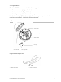
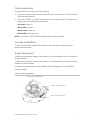
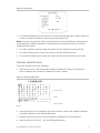
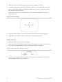
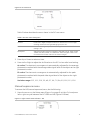
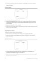
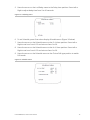
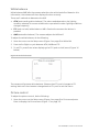
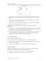
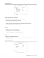
GE Security UVD-EVRDNR(-P) Camera User Manual REV 01.00 • ISS 02SEP09 Copyright © 2009 GE Security, Inc. This document may not be copied in whole or in part or otherwise reproduced without prior written consent from GE Security, Inc., except where specifically permitted under US and international copyright law. Disclaimer The information in this document is subject to change without notice. GE Security, Inc. (“GE Security”) assumes no responsibility for inaccuracies or omissions and specifically disclaims any liabilities, losses, or risks, personal or otherwise, incurred as a consequence, directly or indirectly, of the use or application of any of the contents of this document. For the latest documentation, contact your local supplier or visit us online at www.gesecurity.com. This publication may contain examples of screen captures and reports used in daily operations. Examples may include fictitious names of individuals and companies. Any similarity to names and addresses of actual businesses or persons is entirely coincidental. Trademarks and patents GE and the GE monogram are trademarks of General Electric Company. The UltraView name and logo are trademarks of GE Security. Other trade names used in this document may be trademarks or registered trademarks of the manufacturers or vendors of the respective products. Intended use Use this product only for the purpose it was designed for; refer to the data sheet and user documentation for details. For the latest product information, contact your local supplier or visit us online at www.gesecurity.com. FCC compliance This equipment has been tested and found to comply with the limits for a Class A digital device, pursuant to part 15 of the FCC Rules. These limits are designed to provide reasonable protection against harmful interference when the equipment is operated in a commercial environment. This equipment generates, uses, and can radiate radio frequency energy and, if not installed and used in accordance with the instruction manual, may cause harmful interference to radio communications. You are cautioned that any changes or modifications not expressly approved by the party responsible for compliance could void the user ’s authority to operate the equipment. Certification and compliance European Union directives 1999/5/EC (R&TTE directive): Hereby, GE Security declares that this device is in compliance with the essential requirements and other relevant provisions of Directive 1999/5/EC. 2002/96/EC (WEEE directive): Products marked with this symbol cannot be disposed of as unsorted municipal waste in the European Union. For proper recycling, return this product to your local supplier upon the purchase of equivalent new equipment, or dispose of it at designated collection points. For more information see: www.recyclethis.info. 2004/108/EC (EMC directive): Non-European manufacturers must designate an authorized representative in the Community. Our authorized manufacturing representative is: GE Security B.V., Kelvinstraat 7, 6003 DH Weert, The Netherlands. Contact information For contact information see our Web site: www.gesecurity.com. For contact information see our Web site: www.gesecurity.eu. Content Preface 3 Product description 4 Features 4 User guidelines 4 Components 5 OSD control pad 6 Installation 6 Installation overview 6 Cable connection 7 Camera installation 7 Angle adjustment 7 Focus adjustment 8 Connect the monitor 8 Programming 8 Setup menu 8 Camera identification 9 Light control 10 Manual exposure menu 11 Day/Night control 12 White balance 14 Picture control 14 Focus adjustment 15 Miscellaneous 15 External synchronization 16 Mirror 16 Mask 16 System Time 17 Back default 17 Menu Map 18 UVD-EVRDNR(-P) Camera User Manual i Preface This is the UVD-XP3DNR(-P) Camera. This document includes an overview of the product and detailed instructions explaining: • how to connect the camera; and • how to program the camera; and • how to adjust the camera angle and focus To use this document effectively, you should have the following minimum qualifications: • a basic knowledge of CCTV systems and components; and • a basic knowledge of electrical wiring and low-voltage electrical connections. Read these instructions and all ancillary documentation entirely before installing or operating this product. Note: A qualified service person, complying with all applicable codes, should perform all required hardware installation. Safety terms These terms may appear in this manual: CAUTION: Cautions identify conditions or practices that may result in damage to the equipment or other property. WARNING: Warnings identify conditions or practices that could result in equipment damage or serious personal injury. UVD-EVRDNR(-P) Camera User Manual 3 Product description The UVD-EVRDNR color video camera uses a digital signal processor (DSP) to process video signals. The video camera includes a microcontroller to provide high-quality images with high-color reproduction and sharp pictures. Features Camera features include: • Super HAD (hole accumulated diode) technology with 410,000 pixels NTSC (470,000 PAL). • Use of LSI (large scale integration) digital processors to produce 540 lines of horizontal resolution. • High-resolution picture production using digital signal processors for horizontal and vertical aperture enhancement. • Smart digital automatic BLC (back light control). • Advanced autoexposure system for both fixed iris and autoiris lenses to optimize the amount of light. • Internal or line lock external synchronization. • Long life and high reliability. • OSD control allows eight masks to be shown on the screen for subjects requiring special protection due to privacy concerns. • Advanced OSD (onscreen display) control. • Signal-to-noise ratio better than 48 dB. • Isolated switching power 12 VDC or 24 VAC. • Vandal-resistant housing. User guidelines Use the following guidelines: • Program as many camera settings as possible before mounting the camera. Take appropriate safety precautions while completing programming after installation. • Always use a 12 VDC or 24 VAC UL listed Class 2 power supply to power the camera. • Do not use the camera outside the temperature range specifications: - 22 to 122°F (-30 to +50°C) • If the light source where the camera is installed experiences rapid, widevariations in lighting, the camera may not operate as intended. WARNING: To reduce the risk of fire or electronic shock, do not expose the camera to rain or moisture and do not remove the cover or back. 4 UVD-EVRDNR(-P) Camera User Manual Components The UVD-EVRDNR cameras consist of the following parts: • The camera assembly (Figure 1 below) • Monitor output cable (Figure 2 below) • Mounting screws, wall anchors, and hex key Use the video output BNC and power jack for normal system operation. Use the monitor output cable for installation and maintenance. Figure 1: Camera assembly Camera body Video monitor output System heater Power jack OSD control pad Video output BNC Figure 2: Monitor output cable 1. Monitor output BNC UVD-EVRDNR(-P) Camera User Manual 2. Monitor output RCA 5 OSD control pad The onscreen display (OSD) control pad (Figure 4) is a five-direction joystick that provides the ability to manually control the camera functions. Table 1 below lists the OSD control pad functions and describes their use. Figure 3: OSD control pad OSD control pad Table 1: OSD control pad functions Pad directions Description Up Moves the cursor upward to select an item. Left Moves the cursor left to select or adjust the parameters of the selected item. Right Moves the cursor to the right to select or adjust the parameters of the selected item. Down Moves the cursor downward to select an item. Enter Press the center of the control pad to display the Setup menu. If the selected item has its own menu, press the control pad to enter a submenu. Press the control pad for 2 seconds to save all settings and exit the Setup menu. Installation Complete all the necessary programming before you install the camera. This chapter provides information on how to install the camera and adjust camera angle and focus. Installation overview To install the camera you will need to prepare the mounting surface, make cable connections, and mount the camera. 6 UVD-EVRDNR(-P) Camera User Manual Cable connection To make cable connections, do the following: 1. Connect a coaxial cable from the camera’s BNC connector to a CCTV monitor or video recording device. 2. Connect a 12 VDC or 24 VAC power supply to the power input. The label on the camera gives the following information: Red cable. Power in. Black cable. Power in. White cable. Video out. Black cable. Video ground. Note: For AC24V or DC12V, Black or Red may be used for ground. Camera installation To mount the camera, attach the camera to the mounting surface using the appropriate fasteners Angle adjustment To adjust the horizontal angle of the platform up to 180 degrees, turn the platform (Figure 4 below). To adjust the horizontal angle of the rotor up to 350 degrees, turn the rotor on the platform (Figure 4 below). To adjust the vertical angle of the platform up to 90 degrees, turn the platform (Figure 4 below). Figure 4: Camera adjustment Platform horizontal adjustment Platform vertical adjustment Rotor horizontal adjustment UVD-EVRDNR(-P) Camera User Manual 7 Focus adjustment To adjust the camera zoom and focus, see Figure 5 below and do the following: 1. Loosen the zoom ring thumbscrew. 2. Turn the zoom ring to set the desired zoom. 3. Tighten the zoom ring thumbscrew. 4. Loosen the focus ring thumbscrew. 5. Turn the focus ring to set the desired focus. 6. Tighten the focus ring thumbscrew. Figure 5: Zoom and focus adjustment Zoom ring thumbscrew for VA2 and focus ring for VA9 lens Focus ring thumbscrew for VA2 and zooming ring for VA9 lens Connect the monitor Program the cameras by attaching a standard video monitor to the system. To connect the monitor, do the following: 1. Plug the monitor output cable (Figure 2 on page 5) to the video monitor output connector (Figure 1 on page 5). 2. Connect the BNC cable to the video monitor. 3. Press Enter (see OSD control pad on page 9) to display the Setup menu. Programming This chapter describes how to navigate the programming menus to adjust the camera settings. Setup menu To access the Setup menu (Figure 6 on page 9), do the following: • To navigate to a menu item, press Up, Down, Left, or Right (Table 1 on page 6). • To select the item for adjustments, press Enter. • To display the submenu for the selected item, press Enter. There is a menu map provided on the back page of the manual. 8 UVD-EVRDNR(-P) Camera User Manual Figure 6: Setup menu • To close the Setup menu and return to normal camera operation mode, move the cursor to End at the bottom of the screen and press Enter. Note: If you do not press the OSD control pad for one minute while any setting menu is displayed, all modified data will be stored and the camera will return to normal camera picture mode. • For menu position setting, move the cursor to the K position and press Enter. • To lock the Setup menu, move the cursor to Unlock and press Enter. • To unlock the Setup menu, press Up, Down, and then press Enter (in that order). Camera identification To set the camera ID, do the following: 1. Move the cursor on the Setup menu (Figure 6 above) to Camera ID and press Enter to display the Camera ID submenu (Figure 7 below). Figure 7: Camera identification Character area Editing Command area Blinking 2. Move the cursor to the character you wish to enter. Press Enter and the selected character displays in the editing data area. 3. Repeat the process until you have entered or edited all of the characters. 4. Move the cursor to the in the Editing data area. UVD-EVRDNR(-P) Camera User Manual 9 5. Move the cursor to the blank character position between “z” and “,”. 6. To delete a character, select the character so that it blinks and either move the cursor to the blank character position between the “z” and “,” or move it to the DEL position and press Enter. 7. Move the cursor to Posi and press Enter,. The camera ID displays on screen (Figure 8 below). Figure 8: Camera ID display 8. Press Up, Down, Right, or Left to move the Camera ID to the desired position. 9. Press Enter to fix the ID position and return to the previous menu. Light control To adjust the light control, do the following: 1. Move the cursor on the Setup menu (Figure 6 on page 9) to Light Cntl and press left or right to cycle between the DC Lens and ME (Figure 9 below). Figure 9: Light control menu selection – DC lens 2. To set DC Lens, press Enter when the DC Lens option is displayed. The DC Lens menu appears (Figure 10 on page 11). 10 UVD-EVRDNR(-P) Camera User Manual Figure 10: DC Lens menu Table 2 below describes the menu items in the DC Lens menu. Table 2: DC Lens menu description Menu item Description Iris level Press Left or Right to adjust the level for autoiris lens to control light entering camera (for DC type). Ranging from 0 to 10.. Av:Pk This is the average-to-peak (Av:Pk) setting for AE mode. The default setting is 8:4. Shutspeed Adjust the shutter speed to 1/60 NTSC (1/50 PAL), 1/100, 1/250, 1/500, 1/1000, 1/2,000, 1/5000, or 1/10000 sec. Select a higher value to see movement and a lower value to see clearer images. 3. Press Up or Down to select an item. 4. Press Left or Right to adjust the Av:Pk value on the DC iris lens after level setting. Av. value. The electronic convergence is automatically adjusted for the average photometric method with the average video signal level of the object as the right photometric value. Pk. value. The electronic convergence is automatically adjusted for the peak photometric method with the peak video signal level of the object as the right photometric value. Variation range: 0:12, 1:11, 2:10, 3:9, 4:8, 5:7, 6:6, 7:5, 8:4, 9:3, 10:2, 11:1, 12:0 Manual exposure menu To access the ME (manual exposure) menu, do the following: 1. Move the cursor on the Setup menu (Figure 6 on page 9) to Light Cntl and press left or right to cycle between the DC LENS and ME (Figure 11 below). Figure 11: Light control menu selection – ME UVD-EVRDNR(-P) Camera User Manual 11 2. To set ME, press Enter when the ME option is displayed. The ME menu appears (Figure 12 below). Figure 12: ME menu 3. Press Up or Down to select an item. 4. Adjust the Shutspeed to 1/50, 1/120, 1/250, 1/500, 1/1,000, 1/2,000, 1/5,000, or 1/10,000 sec. Select a higher value to see movement and a lower value to see clearer images. 5. Adjust the Gain to 05, 13, 22, or 30 dB. 6. Move the cursor to select Return and press Enter to set the manual exposure and return to the previous menu. Day/Night control To adjust the white balance, do the following: 1. Move the cursor on the Setup menu (Figure 6 on page 9) to D/N CNTL. 2. Press Left or Right to cycle between LUX /DELAY, SCHEDULE, DAY and NIGHT (Figure 13 below). Figure 13: D/N menu 3. To set Lux/Delay, press Enter when the Lux/Delay option is displayed. The Lux/Delay menu appears (Figure 14 on page 13). 4. Move the cursor on the Lux/Delay menu to the Level position. Press Left or Right to adjust 5 level thresholds. 12 UVD-EVRDNR(-P) Camera User Manual 5. Move the cursor on the Lux/Delay menu to the Delay time position. Press Left or Right to adjust delay time from 5 to 60 seconds. Figure 14: Lux/Delay menu 6. To set Schedule, press Enter when display Schedule menu (Figure 15 below). 7. Move the cursor on the Schedule menu to the D->N time position. Press Left or Right to set hour from 0-23 and minute from 0 to 59. 8. Move the cursor on the Schedule menu to the N->D time position. Press Left or Right to set hour from 0-23 and minute from 0 to 59. 9. Move the cursor on the Schedule menu to the Choice D/N type position to switch D/N mode. Figure 15: Schedule menu UVD-EVRDNR(-P) Camera User Manual 13 White balance White balance (WB) tells the camera what the color white looks like. Based on this information, the camera will then display all colors correctly. There are 3 methods to determine the WB: • ATW (auto tracking white balance). The value used depends on the lighting condition selected. It ensures reliable color reproduction when lighting conditions change frequently. • PTL (push-to-lock)) white balance. WB is fixed at the moment the button is pressed. • AWB (autowhite balance). The camera adjusts the WB itself. To adjust the white balance, do the following: 1. Move the cursor on the Setup menu (Figure 6 on page 9) to White Bal. 2. Press Left or Right to cycle between ATW, AWB and PTL. 3. To set PTL, press Enter when displaying the PTL (push to lock) menu (Figure 16 below). Figure 16: Push to lock menu The camera will process white balance. Observe that PTL push changes to PTL setting. Wait until the character change back to PTL push to exit the menu Picture control To adjust the picture control, do the following: 1. Move the cursor on the Setup menu (Figure 6 on page 9) to Picture and press Enter to display the Picture menu (Figure 17 on page 15). 14 UVD-EVRDNR(-P) Camera User Manual Figure 17: Picture menu 2. Move the cursor to the Bright position, while observing the color video monitor, waveform monitor, or oscilloscope. Press Left or Right to adjust the brightness level. 3. Move the cursor to the Gamma position. Press Left or Right to adjust gamma correction to one of nine gamma curves. 4. Move the cursor to the Aperture position. Press Left or Right to adjust aperture correction in the range 00 to 09 or automatic. Note: Set the aperture to automatic to avoid noise problems in a low light environment. 5. Move the cursor to the BLC (back light compensation) position. BLC electronically compensates for high background lighting to give detail which would normally be silhouetted. Press Left or Right to select BLC on or BLC off. 6. Move the cursor to the AGC (automatic gain control) position. Increasing the AGC level increases camera sensitive at lower light levels. Press Left or Right to increase or decrease the bright level low light condition. Focus adjustment To adjust the focus, do the following 1. Move the cursor on the Setup menu (Figure 6 on page 9) to Focus adj. 2. Press Enter to display the Focus adj menu. This function is the automatic setting for lens focus adjustment. 3. Press Enter when adjustment is complete to return to the Setup menu Miscellaneous Use the Miscellaneous (MISC) menu to adjust camera synchronization and lens applications. To make these adjustments, do the following: 1. Move the cursor on the Setup menu (Figure 6 on page 9) to Misc 2. Press Enter to display the Misc menu (Figure 18 on page 16). UVD-EVRDNR(-P) Camera User Manual 15 Figure 18: Misc menu External synchronization To adjust the external synchronization, do the following: 1. Move the cursor to the Ext sync position. 2. Press Left or Right to align the camera synchronization type. 3. When LineLock is selected, press Enter to display the Ext Sync menu. 4. Press Left or Right to align the sync phase. Mirror To adjust the mirror, do the following: 1. Move the cursor to the Mirror position. 2. Press Left or Right to turn the setting on or off. Mask To adjust the mask, do the following: 1. Move the cursor to the Mask position and press Enter to display the Mask menu (Figure 19 below). Figure 19: Mask submenu 16 UVD-EVRDNR(-P) Camera User Manual 2. Press Left or Right to select one of eight masks to be displayed onscreen to cover the private areas. 3. Move the cursor to the second line. Press Left or Right to show or hide the mask. 4. Move the cursor to Color type. Press Left or Right to select one of three types of masking color (White, Gray, or Black). 5. Move the cursor to Position and press Enter. Press Up, Down, Left, or Right to change the mask position and press Enter when the desired position is selected. 6. Move the cursor to Size and press Enter. Press the Up, Down, Left, or Right to change the mask size and press Enter when the desired size is selected. 7. Move the cursor to select Return and press Enter to set the mask and return to the previous menu. System Time 1. SYSTEM HOUR: Move the cursor to set hour from 0 to 23. 2. SYSTEM MIN: Move the cursor to set minute from 0 to 59. 3. SYSTEM TIME: select DISPLAY or HIDE to turn on time display on OSD or not. Default is HIDE. Back default Select Back default to return the settings to the default settings. UVD-EVRDNR(-P) Camera User Manual 17 Menu Map