1
ACUIX™
High Speed Dome
User Manual
Document 800-01023 – Rev A – 02/08
Revisions
Issue
Date
Revisions
1.00
05/07
New document
1.01
05/07
Revised document (HJZTP privacy zone revision)
A
02/08
Document p/n changed from 900.0849 rev 1.01. Removed 23X WDR & TDN (Hitachi
VK-S454R) camera, added 18X Color (Sony FCB-48C), 18X TDN (Sony FCB-490D)
and 26X WDR & TDN (Sony FCB-990D) cameras. Added Class A warning to p. 3.
FCC Compliance Statement
Information to the User: This equipment has been tested and found to comply with the limits for a Class B digital device.
Pursuant to Part 15 of the FCC Rules, these limits are designed to provide reasonable protection against harmful
interference in a residential installation. This equipment generates, uses, and can radiate radio frequency energy and,
if not installed and used in accordance with the instruction manual, may cause harmful interference to radio
communications. However, there is no guarantee that interference will not occur in a particular installation.
If this equipment does cause harmful interference to radio or television reception, which can be determined by turning
the equipment off and on, the user is encouraged to try to correct the interference. For example, try orienting or
relocating the receiving antenna, increasing the separation between the equipment and receiver, or connecting the
equipment to an outlet on a different circuit.
Caution
Changes or modifications not expressly approved by the party responsible for compliance could void the
user's authority to operate the equipment.
Users of the product are responsible for checking and complying with all federal, state and local
laws and statutes concerning the monitoring and recording of video and audio signals.
Honeywell Video Systems shall not be held responsible for the use of this product in violation of
current laws and statutes.
Canadian Compliance Statement
This Class B digital apparatus complies with Canadian ICES-003.
Cet appareil numérique de la classe B est conforme à la norme NMB-003 du Canada.
Manufacturer’s Declaration of Conformance
The manufacturer declares that the equipment supplied with this guide is compliant with the essential protection
requirements of the EMC directive 89/336/EEC and the Low Voltage Directive LVD 73/23 EEC, conforming to the
requirements of standards EN 55022 for emissions, EN 50130-4 for immunity, and EN 60065 for Electrical Equipment
safety.
Document 800-01023 Rev A
02/08
3
Explanation Of Graphical Objects
The lightning flash with arrowhead symbol within an equilateral triangle is intended to alert the user to the
presence of uninsulated "dangerous voltage" within the enclosure of the product that may be of sufficient
magnitude to constitute a risk of electric shock to the person.
The exclamation point within an equilateral triangle is intended to alert the user to the presence of
important operating and maintenance servicing instructions in the literature accompany the product.
Important Safety Instructions
READ INSTRUCTIONS - All safety and operating instructions should be read before the unit is operated.
1.
RETAIN INSTRUCTIONS - The safety and operating instructions should be retained for future reference.
2.
HEED WARNINGS - All warnings on the unit and in the operating instructions should be adhered to.
3.
FOLLOW INSTRUCTIONS - All operating and use instructions should be followed.
4.
CLEANING - Unplug the unit from the outlet before cleaning. Do not use liquid cleaners or aerosol cleaners. Use
a damp cloth for cleaning.
5.
ATTACHMENTS - Do not use attachments not recommended by the product manufacturer as they may result in
the risk of fire, electric shock, or injury to persons.
6.
ACCESSORIES - Only use accessories specified by the manufacturer. Do not place this product on an unstable
cart, stand, tripod, bracket, or table. The product may fall, causing serious injury to a child or adult and serious
damage to the equipment. Use only with a cart, stand, tripod, bracket, or table recommended by the
manufacturer, or sold with the product. Any mounting of the product should follow the manufacturer's
instructions and should use a mounting accessory recommended by the manufacturer. Wall or shelf mounting
should follow the manufacturer's instructions and should use a mounting kit approved by the manufacturer.
7.
A product and cart combination should be moved with care. Quick stops, excessive force, and uneven surfaces
may cause the product and cart combination to overturn.
8.
POWER SOURCES - This product should be operated only from the type of power source indicated on the
marking label. If you are not sure of the type of power supplied to your facility, consult your product dealer or
local power company.
9.
OVERLOADING - Do not overload outlets and extension cords as this can result in a risk of fire or electric shock.
10. POWER-CORD PROTECTION - Power supply cords should be routed so that they are not likely to be walked on
or pinched by items placed upon or against them, paying particular attention to cords, plugs, and convenience
receptacles.
11. SERVICING - Do not attempt to service this unit yourself as opening or removing covers may expose you to
dangerous voltage or other hazards. Refer all servicing to qualified service personnel.
4
12. DAMAGE REQUIRING SERVICE - Unplug the unit from the outlet and refer servicing to qualified service
personnel under the following conditions:
a.
When the power-supply cord or plug is damaged.
b.
If liquid has been spilled, or objects have fallen into the unit.
c.
If the unit has been exposed to rain or moisture.
d.
If the unit does not operate normally by following the operating instructions. Adjust only those controls that
are covered by the operating instructions as an improper adjustment of other controls may result in damage
and will often require extensive work by a qualified technician to restore the unit to its normal operation.
e.
If the unit has been dropped or the enclosure has been damaged.
f.
When the unit exhibits a distinct change in performance - this indicates a need for service.
13. REPLACEMENT PARTS - When replacement parts are required, be sure the service technician has used
replacement parts specified by the manufacturer or have the same characteristics as the original part.
Unauthorized substitutions may result in fire, electric shock or other hazards.
14. SAFETY CHECK - Upon completion of any service or repairs to this unit, ask the service technician to perform
safety checks to determine that the unit is in proper operating condition.
15. LIGHTNING AND POWER LINE SURGES - For added protection of this unit when it is left unattended and unused
for long periods of time, unplug it from the wall outlet and disconnect the cable system. This will prevent damage
to the unit due to lightning and power-line surges.
16. HEAT - The product should be situated away from heat sources such as radiators, heat registers, stoves, or other
products (including amplifiers) that produce heat.
17. INSTALLATION - Install in accordance with the manufacturer’s instructions. Do not install the unit in an extremely
hot or humid location, or in a place subject to dust or mechanical vibration. The unit is not designed to be
waterproof. Exposure to rain or water may damage the unit.
Prior to installation and use of this product, please observe the following cautions and warnings.
Caution
CAUTION
RISK OF ELECTRIC SHOCK
DO NOT OPEN
CAUTION: TO REDUCE THE RISK OF ELECTRIC SHOCK,
DO NOT REMOVE COVER (OR BACK).
NO USER-SERVICEABLE PARTS INSIDE.
REFER SERVICING TO QUALIFIED SERVICE PERSONNEL.
Document 800-01023 Rev A
02/08
5
Warning
Warning!
Installation and servicing must be performed by qualified personnel in accordance
with current IEE wiring regulations.
Warning!
The PSU must be wired to a double pole fuse spur with 3mm separation. The 3A
fuse spur must be located close to the PSU.
Warning!
Using replacement parts or accessories other than the original manufacturers may
invalidate the warranty.
Warning!
To prevent injury, this apparatus must be securely attached to the wall/ceiling in
accordance with the installation instructions.
6
ACUIX High Speed Dome User Manual
Contents
About This Document . . . . . . . . . . . . . . . . . . . . . . . . . . . . . . . . . . . . . . . . . . . . 15
Overview of Contents. . . . . . . . . . . . . . . . . . . . . . . . . . . . . . . . . . . . . . . . . . . 15
Related Documents . . . . . . . . . . . . . . . . . . . . . . . . . . . . . . . . . . . . . . . . . . . 16
1
Installing the Pan and Tilt Camera Assembly and Lower Dome . . . . . . . . . . . . . . . . . . 17
Introduction . . . . . . . . . . . . . . . . . .
Models . . . . . . . . . . . . . . . . . . . .
Installing the Pan and Tilt Camera Assembly
Installing the Lower Dome . . . . . . . . . .
Indoor or Outdoor Pendant . . . . .
2
.
.
.
.
.
.
.
.
.
.
.
.
.
.
.
.
.
.
.
.
.
.
.
.
.
.
.
.
.
.
.
.
.
.
.
.
.
.
.
.
.
.
.
.
.
.
.
.
.
.
.
.
.
.
.
.
.
.
.
.
.
.
.
.
.
.
.
.
.
.
.
.
.
.
.
.
.
.
.
.
.
.
.
.
.
.
.
.
.
.
.
.
.
.
.
.
.
.
.
.
.
.
.
.
.
.
.
.
.
.
.
.
.
.
.
.
.
.
.
.
.
.
.
.
.
.
.
.
.
.
.
.
.
.
.
.
.
.
.
.
.
.
.
.
.
. 17
. 17
. 18
. 20
. 20
Switch Settings . . . . . . . . . . . . . . . . . . . . . . . . . . . . . . . . . . . . . . . . . . . . 21
Protocol Settings . . . . . . . . . . . .
Baud Rate. . . . . . . . . . . . . . . .
Parity . . . . . . . . . . . . . . . . . .
Sample Switch Settings . . . . . . . .
Honeywell Diamond . . . . .
VCL - RS485 . . . . . . . . .
IntelliBus™ . . . . . . . . . .
Camera Address Settings . . . . . . .
Address Examples . . . . . .
DIP Switch Address Override .
Factory Defaults . . . . . . . . . . . .
Restore Factory Defaults . . .
RJ45 Ethernet Connection . . . . . . .
3
.
.
.
.
.
.
.
.
.
.
.
.
.
.
.
.
.
.
.
.
.
.
.
.
.
.
.
.
.
.
.
.
.
.
.
.
.
.
.
.
.
.
.
.
.
.
.
.
.
.
.
.
.
.
.
.
.
.
.
.
.
.
.
.
.
.
.
.
.
.
.
.
.
.
.
.
.
.
.
.
.
.
.
.
.
.
.
.
.
.
.
.
.
.
.
.
.
.
.
.
.
.
.
.
.
.
.
.
.
.
.
.
.
.
.
.
.
.
.
.
.
.
.
.
.
.
.
.
.
.
.
.
.
.
.
.
.
.
.
.
.
.
.
.
.
.
.
.
.
.
.
.
.
.
.
.
.
.
.
.
.
.
.
.
.
.
.
.
.
.
.
.
.
.
.
.
.
.
.
.
.
.
.
.
.
.
.
.
.
.
.
.
.
.
.
.
.
.
.
.
.
.
.
.
.
.
.
.
.
.
.
.
.
.
.
.
.
.
.
.
.
.
.
.
.
.
.
.
.
.
.
.
.
.
.
.
.
.
.
.
.
.
.
.
.
.
.
.
.
.
.
.
.
.
.
.
.
.
.
.
.
.
.
.
.
.
.
.
.
.
.
.
.
.
.
.
.
.
.
.
.
.
.
.
.
.
.
.
.
.
.
.
.
.
.
.
.
.
.
.
.
.
.
.
.
.
.
.
.
.
.
.
.
.
.
.
.
.
.
.
.
.
.
.
.
.
.
.
.
.
.
.
.
.
.
.
.
.
.
.
.
.
.
.
.
.
.
.
.
.
.
.
.
.
.
.
.
.
.
.
.
.
.
.
.
.
.
.
.
.
.
.
.
.
.
.
.
.
.
.
.
.
.
.
.
.
.
.
.
.
.
.
.
.
.
.
.
.
.
.
.
.
.
.
.
.
.
.
.
.
.
.
.
.
.
.
.
.
.
.
.
.
.
.
.
.
.
.
.
.
.
.
.
.
. 22
. 23
. 24
. 24
. 24
. 25
. 25
. 25
. 26
. 26
. 26
. 27
. 27
Operation and Programming with Honeywell Diamond Protocol . . . . . . . . . . . . . . . . . . 29
Introduction . . . . . . . . . . . . . . . . . . . . . . . . . . . . . . . . . . . . . . . . . . . . . . . . . 29
HEGS5000/5001 Controller . . . . . . . . . . . . . . . . . . . . . . . . . . . . . . . . . . . . . . . . 29
Power Up . . . . . . . . . . . . . . . . . . . . . . . . . . . . . . . . . . . . . . . . . . . . . 29
Reset ACUIX . . . . . . . . . . . . . . . . . . . . . . . . . . . . . . . . . . . . . . . . . . . 30
Manual Control . . . . . . . . . . . . . . . . . . . . . . . . . . . . . . . . . . . . . . . . . . 30
18X Color Camera (FCB-EX48C) . . . . . . . . . . . . . . . . . . . . . . . . . . . . . . . . . 33
18X True Day/Night Camera with Wide Dynamic Range (FCB-EX490D) . . . . . . . . . . . . 33
26X True Day/Night Camera with Wide Dynamic Range (FCB-EX990D) . . . . . . . . . . . . 33
35X True Day/Night Camera with Wide Dynamic Range, Progressive Scanning and Image Stabilization (VK-S654) . . . . . . . . . . . . . . . . . . . . . . . . . . . . . . . . . . . . . . . . . 34
Freeze and Unfreeze Video. . . . . . . . . . . . . . . . . . . . . . . . . . . . . . . . . . . . 35
Flashback Operation . . . . . . . . . . . . . . . . . . . . . . . . . . . . . . . . . . . . . . . 35
NightShot Mode . . . . . . . . . . . . . . . . . . . . . . . . . . . . . . . . . . . . . . . . . 36
Alarm Operation . . . . . . . . . . . . . . . . . . . . . . . . . . . . . . . . . . . . . . . . . 36
Find Home . . . . . . . . . . . . . . . . . . . . . . . . . . . . . . . . . . . . . . . . . . . . 37
Presets . . . . . . . . . . . . . . . . . . . . . . . . . . . . . . . . . . . . . . . . . . . . . . 38
Preset Tours . . . . . . . . . . . . . . . . . . . . . . . . . . . . . . . . . . . . . . . . . . . 43
Rev A
7
Document 800-01023
02/08
Contents
Mimic Tours . . . . . .
Sector IDs . . . . . . .
Privacy Zones . . . . .
HJTZP Controller . . . . . . . .
Power Up . . . . . . .
Reset ACUIX . . . . .
Manual Control . . . .
Freeze/Unfreeze Video
Flashback Operation .
NightShot Mode . . .
Alarm Operation . . .
Find Home . . . . . .
Presets . . . . . . . .
Preset Tours . . . . .
Mimic Tours . . . . . .
Sector IDs . . . . . . .
Privacy Zones . . . . .
4
.
.
.
.
.
.
.
.
.
.
.
.
.
.
.
.
.
.
.
.
.
.
.
.
.
.
.
.
.
.
.
.
.
.
.
.
.
.
.
.
.
.
.
.
.
.
.
.
.
.
.
.
.
.
.
.
.
.
.
.
.
.
.
.
.
.
.
.
.
.
.
.
.
.
.
.
.
.
.
.
.
.
.
.
.
.
.
.
.
.
.
.
.
.
.
.
.
.
.
.
.
.
.
.
.
.
.
.
.
.
.
.
.
.
.
.
.
.
.
.
.
.
.
.
.
.
.
.
.
.
.
.
.
.
.
.
.
.
.
.
.
.
.
.
.
.
.
.
.
.
.
.
.
.
.
.
.
.
.
.
.
.
.
.
.
.
.
.
.
.
.
.
.
.
.
.
.
.
.
.
.
.
.
.
.
.
.
.
.
.
.
.
.
.
.
.
.
.
.
.
.
.
.
.
.
.
.
.
.
.
.
.
.
.
.
.
.
.
.
.
.
.
.
.
.
.
.
.
.
.
.
.
.
.
.
.
.
.
.
.
.
.
.
.
.
.
.
.
.
.
.
.
.
.
.
.
.
.
.
.
.
.
.
.
.
.
.
.
.
.
.
.
.
.
.
.
.
.
.
.
.
.
.
.
.
.
.
.
.
.
.
.
.
.
.
.
.
.
.
.
.
.
.
.
.
.
.
.
.
.
.
.
.
.
.
.
.
.
.
.
.
.
.
.
.
.
.
.
.
.
.
.
.
.
.
.
.
.
.
.
.
.
.
.
.
.
.
.
.
.
.
.
.
.
.
.
.
.
.
.
.
.
.
.
.
.
.
.
.
.
.
.
.
.
.
.
.
.
.
.
.
.
.
.
.
.
.
.
.
.
.
.
.
.
.
.
.
.
.
.
.
.
.
.
.
.
.
.
.
.
.
.
.
.
.
.
.
.
.
.
.
.
.
.
.
.
.
.
.
.
.
.
.
.
.
.
.
.
.
.
.
.
.
.
.
.
.
.
.
.
.
.
.
.
.
.
.
.
.
.
.
.
.
.
.
.
.
.
.
.
.
.
.
.
.
.
.
.
.
.
.
.
.
.
.
.
.
.
.
.
.
.
.
.
.
.
.
.
.
.
.
.
.
.
.
.
.
.
.
.
.
.
.
.
.
.
.
.
.
.
.
.
.
.
.
.
.
.
.
.
.
.
.
.
.
.
.
.
.
.
.
.
.
.
.
.
.
.
.
.
.
.
.
.
.
.
.
.
.
.
.
.
.
.
.
.
.
.
.
.
.
.
.
.
.
.
.
.
.
.
.
.
.
.
.
.
.
.
.
.
.
.
.
.
.
.
.
.
.
.
.
.
.
.
.
.
.
.
.
.
.
.
.
.
.
.
.
.
.
.
.
.
.
.
.
.
.
.
.
.
.
.
.
.
.
.
.
.
.
.
.
.
.
.
.
.
.
.
.
.
.
.
.
.
.
.
.
.
.
.
.
.
.
.
.
.
.
.
.
.
.
.
.
. 47
. 49
. 51
. 54
. 54
. 54
. 54
. 56
. 56
. 56
. 56
. 57
. 57
. 58
. 58
. 59
. 59
.
.
.
.
.
.
.
.
.
.
.
.
.
.
.
.
.
.
.
.
.
.
.
.
.
.
.
.
.
.
.
.
.
.
.
.
.
.
.
.
.
.
.
.
.
.
.
.
.
.
.
.
.
.
.
.
.
.
.
.
.
.
.
.
.
.
.
.
.
.
.
.
.
.
.
.
.
.
.
.
.
.
.
.
.
.
.
.
.
.
.
.
.
.
.
.
.
.
.
.
.
.
.
.
.
.
.
.
.
.
.
.
.
.
.
.
.
.
.
.
.
.
.
.
.
.
.
.
.
.
.
.
.
.
.
.
.
.
.
.
.
.
.
.
.
.
.
.
.
.
.
.
.
.
.
.
.
.
.
.
.
.
.
.
.
.
.
.
.
.
.
.
.
.
.
.
.
.
.
.
.
.
.
.
.
.
.
.
.
.
.
.
.
.
.
.
.
.
.
.
.
.
.
.
.
.
.
.
.
.
.
.
.
.
.
.
.
.
.
.
.
.
.
.
.
.
.
.
.
.
.
.
.
.
.
.
.
.
.
.
.
.
.
.
.
.
.
.
.
.
.
.
.
.
.
.
.
.
.
.
.
.
.
.
.
.
.
.
.
.
.
.
.
.
.
.
.
.
.
.
.
.
.
.
.
.
.
.
.
.
.
.
.
.
.
.
.
.
.
.
.
.
.
.
.
.
.
.
.
.
.
.
.
.
.
.
.
.
.
.
.
.
.
.
.
.
.
.
.
.
.
.
.
.
.
.
.
.
.
.
.
.
.
.
.
.
.
.
.
.
.
.
.
.
.
.
.
. 61
. 61
. 62
. 62
. 63
. 63
. 64
. 64
. 64
. 64
. 66
. 66
. 66
. 68
. 68
. 69
. 69
. 71
. 71
. 72
. 72
.
.
.
.
.
.
.
.
.
.
.
.
.
.
.
.
.
.
.
.
.
.
.
.
.
.
.
.
.
.
.
.
.
.
.
.
.
.
.
.
.
.
.
.
.
.
.
.
.
.
.
.
.
.
.
.
.
.
.
.
.
.
.
.
.
.
.
.
.
.
.
.
.
.
.
.
.
.
.
.
.
.
.
.
.
. 75
. 76
. 76
. 76
. 77
ACUIX Password Feature . . . . . . . . . . . . . . . . . . . . . . . . . . . . . . . . . . . . . . . 79
Enabling the Password Feature . . . . . . . . . . . . . . . . . . . .
Logging On . . . . . . . . . . . . . . . . . . . . . . . . . . . . . . .
Changing the 4-Digit PIN . . . . . . . . . . . . . . . . . . . . . . . .
Resetting Privacy Zone Password (Diamond or IntelliBus Protocols) .
Delete Privacy Zone Programming. . . . . . . . . . . . . . . . . . .
7
.
.
.
.
.
.
.
.
.
.
.
.
.
.
.
.
.
Operation and Programming with IntelliBus™ Protocol . . . . . . . . . . . . . . . . . . . . . . . 75
Factory Default Switch Settings .
Configuration Upload/Download .
Configuration Default . . . . . . .
Configuration Data Saving . . . .
Firmware Upgrade . . . . . . . .
6
.
.
.
.
.
.
.
.
.
.
.
.
.
.
.
.
.
Operation and Programming with Honeywell VCL Protocol . . . . . . . . . . . . . . . . . . . . 61
Introduction . . . . . . . . . . . . . . . . . . . . . . . . . . . . . . .
Power Up . . . . . . . . . . . . . . . . . . . . . . . . . . . . . . . .
Reset ACUIX . . . . . . . . . . . . . . . . . . . . . . . . . . . . . .
Manual Control . . . . . . . . . . . . . . . . . . . . . . . . . . . . .
Lens Control . . . . . . . . . . . . . . . . . . . . . . . . .
Freeze/Unfreeze Video—Preset 95 . . . . . . . . . . . . . . . . . .
Flashback Operation—Preset 96 . . . . . . . . . . . . . . . . . . .
NightShot Mode—Preset 94 . . . . . . . . . . . . . . . . . . . . . .
Find Home . . . . . . . . . . . . . . . . . . . . . . . . . . . . . . .
Presets . . . . . . . . . . . . . . . . . . . . . . . . . . . . . . . . .
Program Preset . . . . . . . . . . . . . . . . . . . . . . . .
Recall Preset . . . . . . . . . . . . . . . . . . . . . . . . .
Preset Tours . . . . . . . . . . . . . . . . . . . . . . . . . . . . . .
Run Preset Tour. . . . . . . . . . . . . . . . . . . . . . . .
Stop a Preset Tour . . . . . . . . . . . . . . . . . . . . . .
Sector IDs. . . . . . . . . . . . . . . . . . . . . . . . . . . . . . . .
Privacy Zones. . . . . . . . . . . . . . . . . . . . . . . . . . . . . .
Mimic Tours. . . . . . . . . . . . . . . . . . . . . . . . . . . . . . .
Programming Mimic Tours . . . . . . . . . . . . . . . . . .
Mimic Tour Operation. . . . . . . . . . . . . . . . . . . . .
Deleting Privacy Zones, Presets, Preset Tours, and Sectors
5
.
.
.
.
.
.
.
.
.
.
.
.
.
.
.
.
.
.
.
.
.
.
.
.
.
.
.
.
.
.
.
.
.
.
.
.
.
.
.
.
.
.
.
.
.
.
.
.
.
.
.
.
.
.
.
.
.
.
.
.
.
.
.
.
.
.
.
.
.
.
.
.
.
.
.
.
.
.
.
.
.
.
.
.
.
.
.
.
.
.
.
.
.
.
.
.
.
.
.
.
.
.
. 79
. 80
. 80
. 81
. 82
On-Screen Setup Menus . . . . . . . . . . . . . . . . . . . . . . . . . . . . . . . . . . . . . . . 83
Introduction . . . . . . . . . . . . . . . . . . . . . . . . . . . . . . . . . . . . . . . . . . . . . . . . . 83
Rev A
8
Document 800-01023
02/08
ACUIX High Speed Dome User Manual
Control/Video Requirements . . . . . . . . . . . . . . . . . . . . . . . . . . . . . . . . . . . . . . . . 83
Honeywell Diamond Protocol . . . . . . . . . . . . . . . . . . . . . . . . . . . . . . . . . . . . . . . 84
Honeywell VCL Protocol . . . . . . . . . . . . . . . . . . . . . . . . . . . . . . . . . . . . . . . . . . 85
Honeywell VCL Coax Control Protocol. . . . . . . . . . . . . . . . . . . . . . . . . . . . . . . . . . . 86
3rd Party Protocols . . . . . . . . . . . . . . . . . . . . . . . . . . . . . . . . . . . . . . . . . . . . . 87
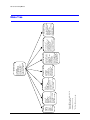
Menu Tree . . . . . . . . . . . . . . . . . . . . . . . . . . . . . . . . . . . . . . . . . . . . . . . . . 88
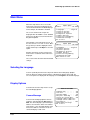
Main Menu . . . . . . . . . . . . . . . . . . . . . . . . . . . . . . . . . . . . . . . . . . . . . . . . . 89
Selecting the Language . . . . . . . . . . . . . . . . . . . . . . . . . . . . . . . . . . . . . 89
Display Options . . . . . . . . . . . . . . . . . . . . . . . . . . . . . . . . . . . . . . . . . . 89
Control Options . . . . . . . . . . . . . . . . . . . . . . . . . . . . . . . . . . . . . . . . . . 92
Diagnostic Options . . . . . . . . . . . . . . . . . . . . . . . . . . . . . . . . . . . . . . . 102
Camera Options, 18X WDR & True Day/Night and 26X WDR, True/Day Night Camera
(FCB-EX490D and FCB-EX990D Respectively) . . . . . . . . . . . . . . . . . . . . . . . . 105
Camera Options, 35X WDR & True Day/Night Camera with Image Stabilization and Motion Detection
(VK-S654) . . . . . . . . . . . . . . . . . . . . . . . . . . . . . . . . . . . . . . . . . . . . 110
Function Programming . . . . . . . . . . . . . . . . . . . . . . . . . . . . . . . . . . . . . 116
Enhanced Settings . . . . . . . . . . . . . . . . . . . . . . . . . . . . . . . . . . . . . . . 123
Appendix A
Troubleshooting . . . . . . . . . . . . . . . . . . . . . . . . . . . . . . . . . . . . .127
Technical Support . . . . . . . . . . . . . . . . . . . . .
Problem: No Video . . . . . . . . . . . . . . . . . . . . .
Problem: General Video Problems (Video Over UTP Only)
Video is Inverted . . . . . . . . . . . . . . . . .
Video is Poor . . . . . . . . . . . . . . . . . . .
Problem: Video, But No Control . . . . . . . . . . . . . .
Problem: Lens Out of Optical Focus . . . . . . . . . . . .
Problem: Cannot Find Home or Does Not Go to a Preset.
Problem: Pan and Tilt is Jerky . . . . . . . . . . . . . . .
Problem: Video Zooms For No Reason . . . . . . . . . .
Appendix B
.
.
.
.
.
.
.
.
.
.
.
.
.
.
.
.
.
.
.
.
.
.
.
.
.
.
.
.
.
.
.
.
.
.
.
.
.
.
.
.
.
.
.
.
.
.
.
.
.
.
.
.
.
.
.
.
.
.
.
.
.
.
.
.
.
.
.
.
.
.
.
.
.
.
.
.
.
.
.
.
.
.
.
.
.
.
.
.
.
.
.
.
.
.
.
.
.
.
.
.
.
.
.
.
.
.
.
.
.
.
.
.
.
.
.
.
.
.
.
.
.
.
.
.
.
.
.
.
.
.
.
.
.
.
.
.
.
.
.
.
.
.
.
.
.
.
.
.
.
.
.
.
.
.
.
.
.
.
.
.
.
.
.
.
.
.
.
.
.
.
.
.
.
.
.
.
.
.
.
.
.
.
.
.
.
.
.
.
.
.
.
.
.
.
.
.
.
.
.
.
.
.
.
.
.
.
.
.
.
.
.
.
.
.
.
.
.
.
.
.
127
127
128
128
128
129
130
130
130
131
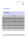
Specifications . . . . . . . . . . . . . . . . . . . . . . . . . . . . . . . . . . . . . .133
ACUIX Housings . . . . . . . . . . . .
ACUIX Cameras . . . . . . . . . . . .
Pan and Tilt Specifications . . . . . . .
Operating/Programming Specifications
ACUIX Lower Dome . . . . . . . . . .
Regulatory Specifications . . . . . . .
Appendix C
.
.
.
.
.
.
.
.
.
.
.
.
.
.
.
.
.
.
.
.
.
.
.
.
.
.
.
.
.
.
.
.
.
.
.
.
.
.
.
.
.
.
.
.
.
.
.
.
.
.
.
.
.
.
.
.
.
.
.
.
.
.
.
.
.
.
.
.
.
.
.
.
.
.
.
.
.
.
.
.
.
.
.
.
.
.
.
.
.
.
.
.
.
.
.
.
.
.
.
.
.
.
.
.
.
.
.
.
.
.
.
.
.
.
.
.
.
.
.
.
.
.
.
.
.
.
.
.
.
.
.
.
.
.
.
.
.
.
.
.
.
.
.
.
.
.
.
.
.
.
.
.
.
.
.
.
.
.
.
.
.
.
.
.
.
.
.
.
.
.
.
.
.
.
.
.
.
.
.
.
.
.
.
.
.
.
.
.
.
.
.
.
.
.
.
.
.
.
.
.
.
.
.
.
.
.
.
.
133
134
135
136
137
137
Pelco Emulation . . . . . . . . . . . . . . . . . . . . . . . . . . . . . . . . . . . . .139
Purpose . . . . . . . . . . . . . . . . . . . . . . . . . . . . . . . . . . . . . . . . . . . . . . . . . . 139
ACUIX Mimic Tour Operation. . . . . . . . . . . . . . . . . . . . . . . . . . . . . . . . . . . . . . . 139
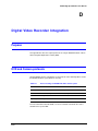
Appendix D
Digital Video Recorder Integration . . . . . . . . . . . . . . . . . . . . . . . . . . .141
Purpose . . . . . . . . . . . . . . . . . . . . . . . . . . . . . . . . . . . . . . . . . . . . . . . . . . 141
DVR and Camera protocols . . . . . . . . . . . . . . . . . . . . . . . . . . . . . . . . . . . . . . . 141
Index . . . . . . . . . . . . . . . . . . . . . . . . . . . . . . . . . . . . . . . . . . . . . . . . . . . . 143
Rev A
9
Document 800-01023
02/08
Contents
Rev A
10
Document 800-01023
02/08
ACUIX High Speed Dome User Manual
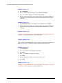
Figures
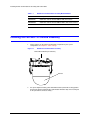
Figure 1-1
ACUIX Pan and Tilt Camera Assembly . . . . . . . . . . . . . . . . . . . . . . . . . . . . 18
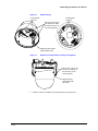
Figure 1-2
ACUIX Housing . . . . . . . . . . . . . . . . . . . . . . . . . . . . . . . . . . . . . . . . 19
Figure 1-3
ACUIX Pan and Tilt Camera Assembly Locking Rails . . . . . . . . . . . . . . . . . . . . . 19
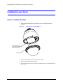
Figure 1-4
Pendant Lower Dome Installation . . . . . . . . . . . . . . . . . . . . . . . . . . . . . . . 20
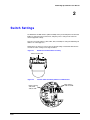
Figure 2-1
ACUIX Pan and Tilt Camera Assembly . . . . . . . . . . . . . . . . . . . . . . . . . . . . 21
Figure 2-2
Location of DIP and Rotary Switches on Main Board . . . . . . . . . . . . . . . . . . . . . 21
Figure 3-1
Sectors IDs. . . . . . . . . . . . . . . . . . . . . . . . . . . . . . . . . . . . . . . . . . . 49
Figure 3-2
Sector ID Coordinates . . . . . . . . . . . . . . . . . . . . . . . . . . . . . . . . . . . . . 50
Rev A
11
Document 800-01023
02/08
Figures
Rev A
12
Document 800-01023
02/08
ACUIX High Speed Dome User Manual
Tables
Table 1-1
ACUIX Pan and Tilt Camera Assembly Model Numbers . . . . . . . . . . . . . . . . . . . . 17
Table 2-1
DIP Switch SW5 ACUIX Protocol Settings . . . . . . . . . . . . . . . . . . . . . . . . . . . 22
Table 2-2
DIP Switch SW6 ACUIX Baud Rate Settings . . . . . . . . . . . . . . . . . . . . . . . . . . 23
Table 2-3
DIP Switch SW6 ACUIX Parity Settings. . . . . . . . . . . . . . . . . . . . . . . . . . . . . 24
Table 2-4
ACUIX Camera Addresses . . . . . . . . . . . . . . . . . . . . . . . . . . . . . . . . . . . 25
Table 3-1
HEGS5000 Joystick Operation . . . . . . . . . . . . . . . . . . . . . . . . . . . . . . . . . 31
Table 3-2
HEGS5000/5001 Camera Lens Control . . . . . . . . . . . . . . . . . . . . . . . . . . . . 32
Table 3-3
35X Camera Feature Dependencies . . . . . . . . . . . . . . . . . . . . . . . . . . . . . . 35
Table 3-4
Pre-programmed Presets . . . . . . . . . . . . . . . . . . . . . . . . . . . . . . . . . . . . 38
Table 3-5
Program Preset Menu Commands . . . . . . . . . . . . . . . . . . . . . . . . . . . . . . . 39
Table 3-6
Preset Title Operation. . . . . . . . . . . . . . . . . . . . . . . . . . . . . . . . . . . . . . 41
Table 3-7
Still Preset Operation . . . . . . . . . . . . . . . . . . . . . . . . . . . . . . . . . . . . . . 42
Table 3-8
Preset Tour Commands . . . . . . . . . . . . . . . . . . . . . . . . . . . . . . . . . . . . 44
Table 3-9
Sector ID Commands. . . . . . . . . . . . . . . . . . . . . . . . . . . . . . . . . . . . . . 50
Table 3-10
Privacy Zone Commands. . . . . . . . . . . . . . . . . . . . . . . . . . . . . . . . . . . . 53
Table 3-11
HJZTP Joystick Operation . . . . . . . . . . . . . . . . . . . . . . . . . . . . . . . . . . . 55
Table 4-1
HJZTP Joystick Operation . . . . . . . . . . . . . . . . . . . . . . . . . . . . . . . . . . . 62
Table 4-2
Pre-programmed Presets ACUIX (VCL) . . . . . . . . . . . . . . . . . . . . . . . . . . . . 65
Table 4-3
Preset Tour Programming Fields . . . . . . . . . . . . . . . . . . . . . . . . . . . . . . . . 67
Table 6-1
Default User PINs . . . . . . . . . . . . . . . . . . . . . . . . . . . . . . . . . . . . . . . . 80
Table 7-1
Program Alarm Field Entry . . . . . . . . . . . . . . . . . . . . . . . . . . . . . . . . . . . 94
Table 7-2
Alarm States . . . . . . . . . . . . . . . . . . . . . . . . . . . . . . . . . . . . . . . . . . 95
Table 7-3
Alarm Input Configuration . . . . . . . . . . . . . . . . . . . . . . . . . . . . . . . . . . . 96
Table 7-4
Pan and Tilt Reverse Operation . . . . . . . . . . . . . . . . . . . . . . . . . . . . . . . . 96
Table 7-5
Find Home Operation. . . . . . . . . . . . . . . . . . . . . . . . . . . . . . . . . . . . . . 97
Table 7-6
Default Function Field Entry . . . . . . . . . . . . . . . . . . . . . . . . . . . . . . . . . . 99
Table 7-7
Default Function Operation . . . . . . . . . . . . . . . . . . . . . . . . . . . . . . . . . . . 99
Table 7-8
Auto Focus Operation . . . . . . . . . . . . . . . . . . . . . . . . . . . . . . . . . . . . 100
Table 7-9
Preset Tour Auto Focus Operation . . . . . . . . . . . . . . . . . . . . . . . . . . . . . . 100
Table 7-10
Cx Code Last Hexadecimal Digit . . . . . . . . . . . . . . . . . . . . . . . . . . . . . . . 104
Table 7-11
High Light White Balance Mode Settings . . . . . . . . . . . . . . . . . . . . . . . . . . 108
Table 7-12
Still Preset Operation . . . . . . . . . . . . . . . . . . . . . . . . . . . . . . . . . . . . . 109
Table 7-13
Auto Exposure Control Mode Settings . . . . . . . . . . . . . . . . . . . . . . . . . . . . 111
Table 7-14
Manual Exposure Modes . . . . . . . . . . . . . . . . . . . . . . . . . . . . . . . . . . . 112
Table 7-15
Auto Slow Shutter Limits . . . . . . . . . . . . . . . . . . . . . . . . . . . . . . . . . . . 113
Rev A
13
Document 800-01023
02/08
Tables
Table 7-16
Still Preset Operation . . . . . . . . . . . . . . . . . . . . . . . . . . . . . . . . . . . . . 114
Table 7-17
Preset Tour Field Entries . . . . . . . . . . . . . . . . . . . . . . . . . . . . . . . . . . . 118
Table 7-18
Recommended Lift Settings for Cable Lengths . . . . . . . . . . . . . . . . . . . . . . . 123
Table 7-19
Recommended Gain Settings for Cable Lengths . . . . . . . . . . . . . . . . . . . . . . 124
Table B-1
Housing Specifications . . . . . . . . . . . . . . . . . . . . . . . . . . . . . . . . . . . . 133
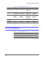
Table B-2
Camera Specifications . . . . . . . . . . . . . . . . . . . . . . . . . . . . . . . . . . . . 134
Table B-3
Pan and Tilt Specifications . . . . . . . . . . . . . . . . . . . . . . . . . . . . . . . . . . 135
Table B-4
Lower Dome Light Loss Specifications. . . . . . . . . . . . . . . . . . . . . . . . . . . . 137
Table B-5
Regulatory Specifications. . . . . . . . . . . . . . . . . . . . . . . . . . . . . . . . . . . 137
Table C-1
ACUIX Mimic Tours Mapped to Pelco Pattern Tours. . . . . . . . . . . . . . . . . . . . . 139
Table D-1
Protocol settings for ACUIX PTZ dome camera system . . . . . . . . . . . . . . . . . . . 141
Rev A
14
Document 800-01023
02/08
ACUIX High Speed Dome User Manual
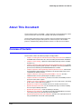
About This Document
This document introduces the ACUIX™, a high-performance PTZ (pan/tilt/zoom) camera
system, and describes how to install, configure, and operate the PTZ dome.
This document demonstrates how to install the camera assembly and lower dome into
the housing and then program and operate the camera using one of the available
protocols. Troubleshooting and Specifications reference sections are also included.
Overview of Contents
This document contains the following chapters and appendixes:
•
•
•
•
•
•
•
•
•
•
•
•
Document 800-01023 Rev A
02/08
Chapter 1, Installing the Pan and Tilt Camera Assembly and Lower Dome, introduces
the ACUIX dome and describes the camera assembly and lower dome installation.
Chapter 2, Switch Settings, explains the different DIP and rotary switches available
and their uses.
Chapter 3, Operation and Programming with Honeywell Diamond Protocol, provides
instruction for programming and operation of an ACUIX set to Honeywell Diamond
protocol and controlled by an HEGS5000/HEGS5001 controller.
Chapter 4, Operation and Programming with Honeywell VCL Protocol, demonstrates
the programming and operation of an ACUIX set to Honeywell VCL protocol and
controlled by an HJZTP controller.
Chapter 5, Operation and Programming with IntelliBus™ Protocol, describes
additional features that are provided by the IntelliBus™ protocol.
Chapter 6, ACUIX Password Feature, provides an overview of the ACUIX password
protection feature and its options.
Chapter 7, On-Screen Setup Menus, covers the on-screen setup menus, and setting
up the control, camera and special features.
Appendix A, Troubleshooting, provides answers for common technical issues.
Appendix B, Replacement Parts, lists the materials that may assist when installing
and servicing the ACUIX product line.
Appendix B, Specifications, shows the ACUIX specifications.
Appendix C, Pelco Emulation, describes the operation of ACUIX Mimic Tours when
set for Pelco protocol and controlled by a Pelco keyboard.
Appendix D, Digital Video Recorder Integration, describes the required protocols for
using an ACUIX PTZ camera with a Honeywell DVR.
15
Related Documents
For more information about topics that are relevant to ACUIX, see the documents listed
below.
16
Document title
Part number
ACUIX Housing Installation Guide
800-01760
ACUIX Quick Set-Up Poster
800-00248
HDPRM2 Parapet Mount Install Guide
900.0877
HDXWM1 Decorative Wall Mount Install Guide
900.0868
HDCM1 Indoor Pendant Mount Install Guide
900.0869
ACUIX High Speed Dome User Manual
1
Installing the Pan and Tilt Camera Assembly
and Lower Dome
Introduction
This chapter describes installing the ACUIX pan and tilt camera assembly in the housing
and installing the lower dome on the housing. Installation of the camera assembly is the
same regardless of the housing type. The following instructions assume the housing
mount has been installed and the housing has been installed on the mount. See Related
Documents on page 16 for the names and part numbers of the mount and housing
installation guides.
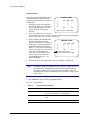
Models
Refer to the following table for the ACUIX pan and tilt camera assembly model numbers.
Table 1-1
Document 800-01023 Rev A
02/08
ACUIX Pan and Tilt Camera Assembly Model Numbers
Model Number
Description
HDCAN0000
ACUIX Pan and Tilt with 18X Color, NTSC Camera
HDCAP0000
ACUIX Pan and Tilt with 18X Color, PAL Camera
HDCJN0000
ACUIX Pan and Tilt with 18X WDR & TDN, NTSC Camera
HDCJP0000
ACUIX Pan and Tilt with 18X WDR & TDN, PAL Camera
HDCFN0000
ACUIX Pan and Tilt with 26X WDR & TDN, NTSC Camera
17
Installing the Pan and Tilt Camera Assembly and Lower Dome
Table 1-1
ACUIX Pan and Tilt Camera Assembly Model Numbers
Model Number
Description
HDCFP0000
ACUIX Pan and Tilt with 26X WDR & TDN, PAL Camera
HDCGN0000
ACUIX Pan and Tilt with 35X WDR & TDN w/ EIS, NTSC Camera
HDCGP0000
ACUIX Pan and Tilt with 35X WDR & TDN w/ EIS, PAL Camera
Installing the Pan and Tilt Camera Assembly
1.
Set the switches on the printed circuit board as required for your system
configuration. See Chapter 2, Switch Settings.
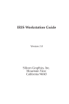
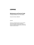
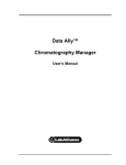
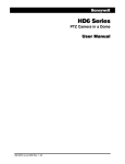
Figure 1-1
ACUIX Pan and Tilt Camera Assembly
Printed Circuit Board (Set Switches)
Camera
2.
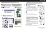
18
Line up the alignment label (yellow label with black dot) below the locking guide in
the housing with the alignment label (yellow label with black dot) on the locking rail
on the pan and tilt camera assembly.
ACUIX High Speed Dome User Manual
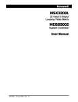
Figure 1-2
ACUIX Housing
Locking guide
(2 places)
Locking guide
(2 places)
Ensure the rails on the
pan and tilt assembly
lock into the holes on
the housing guides
Alignment label (yellow
label with black dot)
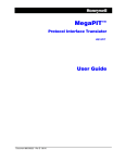
Figure 1-3
ACUIX Pan and Tilt Camera Assembly Locking Rails
Ensure the 2 rails on the
camera assembly lock
into the holes on the
housing guides
Alignment label
(yellow label with
black dot)
3.
Document 800-01023 Rev A
02/08
Push the camera assembly into the housing until it snaps into place.
19
Installing the Pan and Tilt Camera Assembly and Lower Dome
Installing the Lower Dome
Indoor or Outdoor Pendant
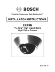
1.
Hook the lanyard attached to the lower dome on the retaining bracket in the
housing.
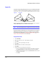
Figure 1-4
Pendant Lower Dome Installation
Hook lanyard from
lower dome to retaining
bracket in housing
Trim ring
20
2.
Ensure the trim ring is in place around the lower dome.
3.
Press the lower dome into the housing.
4.
Secure the lower dome to the housing by installing the two screws provided with the
lower dome.
ACUIX High Speed Dome User Manual
2
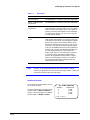
Switch Settings
The ACUIX has two DIP switches (SW5 and SW6) on the pan and tilt printed circuit board
(PCB) for setting the protocol, baud rate, and parity. These settings must match the
control equipment settings.
There are four rotary switches (SW1, SW2, SW3, and SW4) for setting the ACUIX logical
address for control purposes.
A DIP switch can also be used to restore the default settings and another DIP switch to
override the switch settings for the logical address.
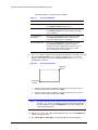
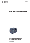
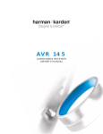
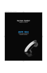
Figure 2-1
ACUIX Pan and Tilt Camera Assembly
Printed circuit board
Figure 2-2
Location of DIP and Rotary Switches on Main Board
Rotary switches
SW1, SW2,
SW3, & SW4
Document 800-01023 Rev A
02/08
DIP switches
SW5 and SW6
21
Switch Settings
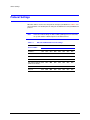
Protocol Settings
DIP switch SW5 is used to select the protocol setting for your ACUIX. See Table 2-1 for
more information. The default protocol setting for the ACUIX is the Honeywell Diamond
protocol.
Note
If there are invalid settings on SW5 or SW6 regarding protocol or baud rate,
the system defaults to Diamond protocol at 9600 baud rate.
Table 2-1
DIP Switch SW5 ACUIX Protocol Settings
Switch Position
Protocol Name
22
1
2
3
4
5
6
7
8
IntelliBus™
OFF
OFF
OFF
OFF
OFF
OFF
OFF
OFF
Diamond
ON
OFF
OFF
OFF
OFF
OFF
OFF
OFF
MAXPRO Mode
OFF
ON
OFF
OFF
OFF
OFF
OFF
OFF
VCL - RS485
ON
ON
OFF
OFF
OFF
OFF
OFF
OFF
VCL Video Telemetry OFF
(Control over Coax)
OFF
ON
OFF
OFF
OFF
OFF
OFF
Pelco P
ON
OFF
ON
OFF
OFF
OFF
OFF
OFF
Pelco D
OFF
ON
ON
OFF
OFF
OFF
OFF
OFF
ACUIX High Speed Dome User Manual
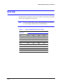
Baud Rate
DIP SW6, position 1 through 4 are used to set the baud rate. The baud rate of the ACUIX
and the control equipment must be the same.
Note
If there are invalid settings on SW5 or SW6 regarding protocol or baud rate,
the system defaults to Diamond protocol at 9600 baud rate.
Table 2-2
DIP Switch SW6 ACUIX Baud Rate Settings
Switch Position
Baud Rate
Document 800-01023 Rev A
02/08
1
2
3
4
600
OFF
OFF
OFF
OFF
1200
ON
OFF
OFF
OFF
2400
OFF
ON
OFF
OFF
4800
ON
ON
OFF
OFF
9600
OFF
OFF
ON
OFF
19200
ON
OFF
ON
OFF
38400
OFF
ON
ON
OFF
57600
ON
ON
ON
OFF
115200
OFF
OFF
OFF
ON
23
Switch Settings
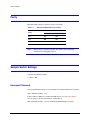
Parity
DIP Switch SW6, positions 5 and 6 are used to set the parity.
Table 2-3
DIP Switch SW6 ACUIX Parity Settings
Switch Position
Parity
5
6
None
OFF
OFF
Even
ON
OFF
Odd
OFF
ON
Note
SW6, position 7 should be kept OFF. This switch is only used during
development for debugging purposes.
Sample Switch Settings
Legend for the following samples:
1 = On/ 0 = Off
Honeywell Diamond
For Honeywell Diamond protocol, the commonly used setting is 9600 baud, even parity.
SW5 - 10000001 (positions 1–8).
In above SW5–8 is ON to force reading from DIP switches. See DIP Switch Address
Override, page 26, for more information on setting SW5–8.
SW6 - 00101000 (positions 1–8) sets the ACUIX to 9600 baud with even parity.
24
ACUIX High Speed Dome User Manual
VCL - RS485
For VCL - RS485 protocol, the commonly used setting is 9600 baud, no parity.
SW5 - 11000001 (positions 1–8).
In above SW5–8 is ON to force reading from DIP switches. See DIP Switch Address
Override, page 26, for more information on setting SW5–8.
SW6 - 00100000 (positions 1–8) sets the ACUIX to 9600 baud with no parity.
IntelliBus™
SW5 - 00000001 (positions 1–8).
In above SW5–8 is ON to force reading from DIP switches. See DIP Switch Address
Override, page 26, for more information on setting SW5–8.
SW6 - 01100000 (positions 1–8) sets the ACUIX to 38400 baud with no parity.
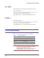
Camera Address Settings
Address selection is via rotary switches SW1, SW2, SW3, and SW4.
Table 2-4
Address
Value
SW1
Units digit
SW2
Tens digit
SW3
Hundreds digit
SW4
Thousands digit
Caution
Document 800-01023 Rev A
02/08
ACUIX Camera Addresses
The ACUIX can be addressed from 0000 to 9999. The addressing
scheme may be restricted due to the limitations of the controller
being used to control the ACUIX. For example, the
HEGS5000/HEGS5001 controllers can control camera addresses 1
to 256. The HJZTP can control camera addresses 1 to 128.
25
Switch Settings
Address Examples
1.
To set the camera address to 1, set SW1 = 1, SW2 = 0, SW3 = 0, SW4 = 0
(CAM - 0001).
2.
To set the camera address to 125, set SW1 = 5, SW2 = 2, SW3 = 1, SW4 = 0
(CAM - 0125).
Note
If the ACUIX is set to address 0000, it will respond to control commands for
any address. That is, if the ACUIX is set to address 0000 and the operator
sends control commands for address 2, the ACUIX addressed 0000 will
perform the commands for address 2. No validation is performed on the
addresses by the ACUIX.
DIP Switch Address Override
DIP Switch SW5–8 can be set so the ACUIX sets the camera address based on the rotary
switch settings or from memory. SW5–8 should be kept ON during normal operation so that
the logical address can be changed from the on-screen setup menus.
SW5–8
OFF
Logical address stored in memory overrides the DIP Switch settings.
ON
The ACUIX is forced to read from the rotary switches and overrides the logical
address stored in memory.
Factory Defaults
The factory default settings are as follows:
26
Protocol
Honeywell Diamond
Baud rate
9600
Parity
No parity
Address
Even
Termination
None
ACUIX High Speed Dome User Manual
Restore Factory Defaults
SW5–7 is looked at only when the ACUIX is powered up. If this switch is ON at the time of
power up, the factory defaults will be restored. For an already powered dome, you must
place switch SW5–7 in the ON position, and then cycle the power to the ACUIX for the
factory default settings to be restored.
SW5–7
OFF
Normal Operation.
ON
Restore Factory Default settings.
Note
It is not advisable to keep this DIP switch (SW5–7) in the ON position. Once
the factory default is achieved after a single power cycling, place SW5–7
back to the OFF position.
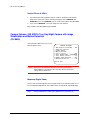
RJ45 Ethernet Connection
The RJ45 connector located on the ACUIX interface board is used for production use and
testing only and has no functionality during normal dome use. This will not damage your
ACUIX dome, but may affect your network. Honeywell recommends you DO NOT connect
your network to the RJ45 connector.
Document 800-01023 Rev A
02/08
27
Switch Settings
28
ACUIX High Speed Dome User Manual
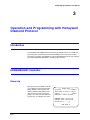
3
Operation and Programming with Honeywell
Diamond Protocol
Introduction
The availability of the ACUIX features and the way the ACUIX features are controlled is
governed by the controller being used and the ACUIX protocol setting. This chapter
describes the operation of the ACUIX set to Honeywell Diamond protocol and controlled
by a model HEGS5000, HEGS5001 or HJZTP joystick controller.
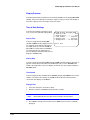
HEGS5000/5001 Controller
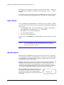
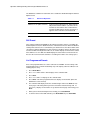
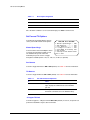
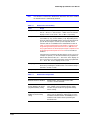
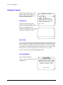
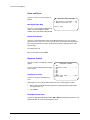
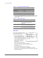
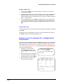
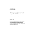
Power Up
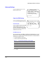
Upon power up of the ACUIX, a start up
screen displays the protocol, baud rate,
parity, data bits, camera model, and
software (VXWorks and FPGA) release
dates and versions. If the Honeywell
startup screen has been turned off in the
setup menus, an X displays in its place.
---- ACUIX Dome ---Protocol ........... Diamond
9600 baud no parity -8bits
Camera ............... Model
Honeywell Video Systems
DOMEApp date version B0
FPGABit date version B1
Please wait......_8
CAM-0006 M
Document 800-01023 Rev A
02/08
29
Operation and Programming with Honeywell Diamond Protocol
If the ACUIX is set to find home on startup, the message Finding Home... displays on
the monitor. Once the ACUIX has found home, the message Home Found... is briefly
displayed.
If the ACUIX is not set to find home on startup, the ACUIX finds home when it receives the
first control command. After the ACUIX finds home, the operator can control the ACUIX.
Reset ACUIX
To reset an ACUIX using an HEGS5000/5001 controller you must be logged in as a Master
user on the controller. This reset is the same as if power was removed from the ACUIX and
then restored.
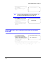
1.
Press Dome Menu. Dome Setup Menu displays in the controller’s LCD window. If
Dome Setup Menu is not displayed, press + or - until it displays.
2.
Press Enter to access the Dome Setup Menu.
3.
Press 4 for Diagnostic Options.
4.
Press 7 for Scan and Camera Reset.
You can also press Clear/Manual on the HEGS5000/5001 controller four times to reset the
ACUIX.
Note
To restore the ACUIX to factory default settings, you can access the
on-screen setup menus or make use of the DIP switches as described in
Restore Factory Defaults on page 27.
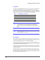
Manual Control
Manual control of an ACUIX dome includes pan, tilt, zoom, focus, and iris. To manually
control an ACUIX, the address of the ACUIX must be selected as the control camera. When
an operator performs a command at the controller, the controller sends out the control
command with the control camera address.
Example: The operator has camera 2 selected as the control camera on the controller. The
operator performs the tilt function on the controller. The controller sends out the tilt
command to camera address 2. All the ACUIX domes on the control loop receive the
command, but only the ACUIX with address 2 performs the tilt command. If the ACUIX is
set to address 0, CAM-0000, the ACUIX responds to commands for all addresses.
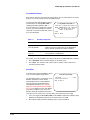
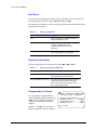
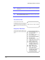
When the ACUIX is being manually controlled the letter
M (manual) is added to the camera ID. The camera
message must be turned on in the Display Options
menu for it to be added to the video signal and viewed
on a monitor.
30
CAM-0001 M
ACUIX High Speed Dome User Manual
Pan and Tilt
The joystick on the HEGS5000/5001 controller is used to control the pan and tilt functions
of the ACUIX. The maximum pan speed is selectable between 120°, 240°, or 480° per
second. The maximum tilt speed is one-half the maximum pan speed. If the maximum pan
speed is set to 240° per second, the maximum tilt speed is set to 120° per second. The pan
and tilt speeds are set in the on-screen setup menus under Control Options.
Table 3-1
HEGS5000 Joystick Operation
Action
Function
Joystick up
Tilt up
Joystick down
Tilt down
Joystick left
Pan left
Joystick right
Pan right
Note
If the pan and/or tilt functions of the ACUIX are reversed through the
on-screen setup menus, joystick up performs tilt down, joystick down
performs tilt up, joystick left performs pan right and joystick right performs
pan left.
Note
The HEGS5000/HEGS5001 controller will not function properly if the polarity
of the 2-wire RS485 lines is reversed.
Lens Control
The camera/lens package in the ACUIX provides automatic exposure control. The lens iris,
camera video gain, and camera shutter speed adjust automatically to the brightness of the
scene (unless manual exposure, or iris, is selected at the controller).
Under normal conditions the camera shutter is set to 1/60s for NTSC and the video gain is
set to 1 (0dB). As the light level varies in this normal area the lens iris is opened and closed
to compensate for the variations in the light level.
If the light level increases beyond the level that can be compensated for by closing the lens
iris the camera will begin to decrease the time that the electronic shutter is opened down to
a minimum of 1/10000s.
If the light level decreases when the camera is operating at a shutter speed of less than
normal (see above) the shutter time will increase until it reaches the normal time and if the
light level decreases beyond the level that can be compensated for by opening the lens iris
the camera will begin increasing its video gain.
Document 800-01023 Rev A
02/08
31
Operation and Programming with Honeywell Diamond Protocol
If the camera is operating with the video gain higher than the minimum and the light level
increases the video gain will be decreased until it reaches the minimum value.
If the camera has auto slow shutter mode and it is set to auto and the light level continues
to decrease beyond the point where the camera’s maximum video gain is reached, then the
time that the electronic shutter is open will increase beyond 1/60s for NTSC until it reaches
the maximum shutter time (1/2 to 2s depending on the camera). This will cause blurred
motion and slow updating of the picture.
If the camera is in the slow shutter mode and the light level increases the shutter time will
decrease until it reaches the normal setting (see above).
If the camera has True Day Night (TDN) functionality the IR block filter will be removed and
the picture switched to black and white at a preselected increased gain and shutter time
point. This point is either detected by the camera or by the ACUIX depending on the camera
type and can be modified in either case. The details of the operation of the TDN feature
depends on the specific camera being used.
If the camera has TDN and the IR block filter has been removed and the light level increases
beyond the TDN transition point set by the camera or the ACUIX the IR block filter will be
inserted and the picture is returned to color.
For all cameras with manual exposure control (also referred to as manual iris control) the
same sequence is followed when increasing and decreasing manual exposure control.
When in manual exposure control the TDN function is also controlled manually, however, it
remains independent of the manual exposure control.
If the unit is powered down then back up, the ACUIX comes back up in the iris mode it was
in when it was powered down.
The lens auto focus feature can be set to adjust automatically when the zoom setting
changes or when the pan, tilt, or zoom settings change. The lens auto focus can also be
disabled so the operator has to manually focus the lens. If the ACUIX is programmed for
either of the two auto focus settings, the operator can manually control the lens focus. The
minimum focus distance is set at 1.0 meter (3.3 ft) from the camera lens in both manual and
automatic focus modes.
Refer to Table 3-2 for information on manually controlling the camera lens features using
the HEGS5000/5001.
Table 3-2
32
HEGS5000/5001 Camera Lens Control
Control
Function
Joystick Knob
Rotate the joystick knob clockwise and counterclockwise
for zoom in and out functions, respectively. The manual
speed of the zoom function is set through the on-screen
setup menus under Camera Options.
Auto Iris
Places the lens in auto exposure mode.
Iris Open
Manually increases exposure to lighten the scene.
Iris Close
Manually decreases exposure to darken the scene.
Focus Near/Focus Far
Manually focuses the lens.
ACUIX High Speed Dome User Manual
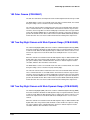
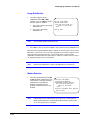
18X Color Camera (FCB-EX48C)
The 18X color camera has an 18X optical zoom lens with a digital zoom function up to 216X.
The White Balance can be set to manual mode. If the unit is in manual mode, the red and
blue gain settings can be set between 0 (low) and 255 (high).
The 18X color camera features motion detection. There are four default motion detection
zones. If motion detection is set to ON, and the camera detects motion in any one of the
four zones, the message Motion Detected displays on the video. The message remains
on the video until the ACUIX either is controlled by the operator, responds to an alarm, or
performs the default function. Once motion is detected, the ACUIX automatically disables
motion detection. The user must re-enable motion detection through the setup menus.
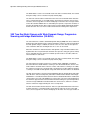
18X True Day/Night Camera with Wide Dynamic Range (FCB-EX490D)
The 18X True Day/Night (TDN) camera has a feature called Wide Dynamic Range (WDR)
that can be enabled or disabled. The wide dynamic range is only functional if the camera is
in auto iris mode. When the wide dynamic range is enabled, the camera scans the scene
and sets the exposure level so both the dark areas and bright areas in a scene can be
viewed.
When the controller is in manual iris mode the wide dynamic range is disabled and the auto
digital shutter does not go below 1/60s for NTSC or 1/50s for PAL. The exposure setting
(iris, gain or shutter) that is controlled when the camera is in manual exposure mode is
selectable, while the other two will be in auto mode.
The White Balance can be set to manual mode. If the unit is in manual mode, the red and
blue gain settings can be set between 0 (low) and 255 (high).
The 18X color camera features motion detection. There are four default motion detection
zones. If motion detection is set to ON, and the camera detects motion in any one of the
four zones, the message Motion Detected displays on the video. The message remains
on the video until the ACUIX either is controlled by the operator, responds to an alarm, or
performs the default function. Once motion is detected, the ACUIX automatically disables
motion detection. The user must re-enable motion detection through the setup menus.
26X True Day/Night Camera with Wide Dynamic Range (FCB-EX990D)
The 26X True Day/Night (TDN) camera has a feature called Wide Dynamic Range (WDR)
that can be enabled or disabled. The wide dynamic range is only functional if the camera is
in auto iris mode. When the wide dynamic range is enabled, the camera scans the scene
and sets the exposure level so both the dark areas and bright areas in a scene can be
viewed.
When the controller is in manual iris mode the wide dynamic range is disabled and the auto
digital shutter does not go below 1/60s for NTSC or 1/50s for PAL. The exposure setting
(iris, gain or shutter) that is controlled when the camera is in manual exposure mode is
selectable, while the other two will be in auto mode.
Document 800-01023 Rev A
02/08
33
Operation and Programming with Honeywell Diamond Protocol
The White Balance can be set to manual mode. If the unit is in manual mode, the red and
blue gain settings can be set between 0 (low) and 255 (high).
The 26X color camera features motion detection. There are four default motion detection
zones. If motion detection is set to ON, and the camera detects motion in any one of the
four zones, the message Motion Detected displays on the video. The message remains
on the video until the ACUIX either is controlled by the operator, responds to an alarm, or
performs the default function. Once motion is detected, the ACUIX automatically disables
motion detection. The user must re-enable motion detection through the setup menus.
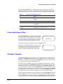
35X True Day/Night Camera with Wide Dynamic Range, Progressive
Scanning and Image Stabilization (VK-S654)
The 35X camera has a feature called Wide Dynamic Range (WDR) that can be enabled or
disabled. The wide dynamic range is only functional if the camera is in auto iris mode. When
the wide dynamic range is enabled, the camera scans the scene and sets the exposure
level so both the dark areas and bright areas in a scene can be viewed.
When the controller is in manual mode the wide dynamic range is disabled and the auto
digital shutter does not go below 1/60s for NTSC. The exposure setting (iris, gain or shutter)
that is controlled when the camera is in manual exposure mode is selectable, while the
other two will be in auto mode.
The White Balance can be set to manual mode. If the unit is in manual mode, the red and
blue gain settings can be set between 0 (low) and 511 (high).
The 35X camera also features progressive scanning, image stabilization, and motion
detection. When the default interlace scanning is set to the default ON, the camera scans
all the odd lines and then all the even lines of video. If the interlace scanning is set to OFF,
the camera is in progressive scan mode and scans all the lines of video. When the interlace
scanning is set to ON, the wide dynamic range and motion detection features are disabled.
The 35X camera features electronic Image Stabilization (EIS) to eliminate blurry and jumpy
video when the camera is bumped or jostled due to wind or traffic vibration. If the Image
Stabilization is set to ON, the motion detection feature is disabled. When EIS is enabled, the
camera reduces the area of the CCD that is scanned. This causes the video displayed on
the monitor to appear to have zoomed in. When the dome undergoes a pan or tilt operation,
electronic Image Stabilization is disabled while the camera moves, and then re-enables
after the camera has stopped moving for a five second period.
The 35X camera features motion detection. There are eight default motion detection zones.
If motion detection is set to ON, and the camera detects motion in any one of the eight
zones, the message Motion Detected displays on the video. The message remains on
34
ACUIX High Speed Dome User Manual
the video until the ACUIX either is controlled by the operator, responds to an alarm, or
performs the default function. Once motion is detected, the ACUIX automatically disables
motion detection. The user must re-enable motion detection through the setup menus.
Table 3-3
35X Camera Feature Dependencies
If:
Then:
Motion detection is enabled
Interlace scanning and image stabilization are
disabled.
Image stabilization is enabled
Motion detection is disabled.
Interlace scanning is enabled
Wide Dynamic Range (WDR) and motion detection
are disabled.
Wide Dynamic Range (WDR)
is enabled
Interlace scanning must be disabled and the
ACUIX must be in auto iris mode.
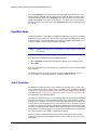
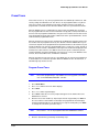
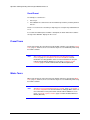
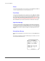
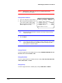
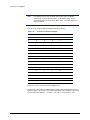
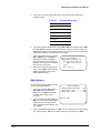
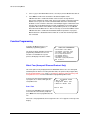
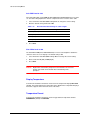
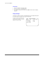
Freeze and Unfreeze Video
Press Freeze Video on the controller to toggle between
freezing and unfreezing the current video scene. When
the video is frozen, an asterisk displays on the same line
as the camera ID, and the video remains frozen on the
current scene until the operator unfreezes the video.
*
CAM-0001 M
If the camera ID display is turned off, the asterisk displays by itself.
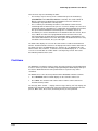
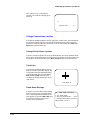
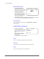
An operator can manually control the camera or send
the camera to a Preset, but the video display does not
change. When the video is unfrozen, the scene the
camera is viewing is outputted on the video signal.
*
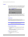
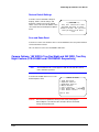
Flashback Operation
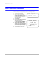
The patented flashback function enables the user to quickly return to a scene of interest.
Initially pressing Flashback when viewing a scene saves that scene as a flashback scene.
Moving to a subsequent scene and pressing Flashback both saves that scene and returns
the camera to the previously saved flashback scene.
For instance, after the ACUIX has found home (initialized), the operator finds a scene of
interest. The operator presses Flashback and ACUIX stores that scene (Scene A). If the
operator then moves to another scene (Scene B) and presses Flashback, ACUIX saves
Scene B and returns to Scene A. Pressing Flashback again returns the camera to Scene
B. If the operator then manually moves to another scene (Scene C) and presses Flashback
the ACUIX returns to Scene A. This occurs because the last time Flashback was pressed
the camera was at Scene A, therefore, saving that scene in the Flashback memory.
The only exception is during a Preset Tour operation. For example, Flashback is pressed
and the ACUIX returns to Scene A. After that, a Preset Tour is started. During the Preset
Tour, the ACUIX moves from Preset 2 to Preset 3. If Flashback is pressed while the ACUIX
is at Preset 3, the Preset Tour will be terminated and the ACUIX will go back to Preset 2.
Document 800-01023 Rev A
02/08
35
Operation and Programming with Honeywell Diamond Protocol
Each time Flashback is pressed thereafter, the ACUIX toggles between Presets 2 and 3
until the ACUIX is manually controlled. After manual control, the flashback feature returns
to normal operation. The next time Flashback is pressed, the current scene (Scene D) is
stored and the ACUIX returns to the last Flashback scene (in this case, Scene A) prior to
the start of the Preset Tour. Once at Scene A, if Flashback is pressed, the ACUIX goes back
to Scene D.
NightShot Mode
The NightShot feature is only available on ACUIX units with cameras that have a removable
IR block filter. These cameras are often referred to as true day/night (TDN) cameras. When
the IR block filter is removed (NightShot on), the camera sensitivity for viewing dark scenes
is increased and the video is converted to black and white.
Note
NightShot mode must be set to manual in the setup menus to control it from
the controller.
To toggle between standard operation and NightShot mode:
1.
Press Run Menu continuously until NightShot displays on the controller’s LCD.
2.
Press Enter.
A message (NightShot On or NightShot Off) displays on the monitor where the ACUIX
video is viewed.
The NightShot mode can also be toggled on and off using Preset 99. Refer to Recall
Presets on page 41 for more information on sending the ACUIX to a Preset.
Alarm Operation
The ACUIX has 4 alarm inputs that can be configured as normally open or closed. If the
contact deviates from normal, an alarm occurs. The ACUIX can be programmed (through
the on-screen setup menus) to activate a Preset, a Preset Tour, or Mimic Tour in response
to an alarm. Refer to Program Alarms, page 93, in Chapter 7, On-Screen Setup Menus for
more information on programming alarms.
The alarms are sampled 16 times per second. After the alarm has been activated, the ACUIX
determines if a function has been programmed for that alarm, and if that alarm is enabled.
If either of those conditions are not met, the alarm will be discarded. If both conditions are
met, the alarm is considered triggered. If no other alarm is in service, the alarm is serviced.
The function assigned to the alarm is performed. The ACUIX stays in this alarm state until
the alarm is acknowledged. Any additional alarms that are triggered are not serviced until
the first alarm is acknowledged. If there is more than one alarm waiting to be serviced, they
are serviced in order of alarm number, starting with the lowest.
An alarm cannot be reactivated until it has been both acknowledged, and the contact
returned to normal. After acknowledgment and the contact change of state, the cycle can
begin again.
36
ACUIX High Speed Dome User Manual
There are three ways to acknowledge an alarm:
•
•
•
The first way is to press the key on the controller that represents the ESC key
(Clear/Manual on the HEGS5000/HEGS5001 controller). This sends a Return to
Manual command to the ACUIX. When the ACUIX receives this command, it
acknowledges any alarm that is currently active.
The second way to acknowledge an alarm is to take manual control. This will
acknowledge ALL the alarms that are present—even those waiting to be serviced. To
acknowledge alarms sequentially: press a PTZ button to acknowledge the first alarm,
then press another PTZ button to acknowledge the second alarm, and so on.
The final way is to use the default function. The default function runs a Preset, Preset
Tour, or Mimic Tour after a user-programmable amount of inactive time. It also
auto-acknowledges an alarm after the programmable delay. It acknowledges each
active alarm until all alarms are inactive. At that point, the default function runs. If any
new alarms come in after this, the cycle starts again.
The alarm status displays on-screen on the same text line set aside for the Camera ID
number. The Camera ID does not have to be displayed in order to view the alarm status. If
any alarms are active, the ACUIX displays AL-. After the AL-, the ACUIX lists all active
alarms in order. Thus, if alarms 1, 3, and 4 are active, the ACUIX displays AL-1 3 4. There
is no on-screen indication as to which alarm is currently being serviced. That can be
determined by what function is active.
Find Home
The ACUIX has a mechanical “Home” position. The home position is a pan and tilt position
used as a reference point for controlling and programming the ACUIX. Upon power-up of
the unit, the ACUIX must find its home position before it responds to any control
commands.
The ACUIX can be sent to its home position from the HEGS5000 controller as follows:
1.
Press Run Menu until Find Home displays on the controller’s LCD screen.
2.
Press Enter. The controller sends out the data to send the control camera to its
mechanical home position.
The message, Home Found... displays. If the message, Homing Failed, displays, the
ACUIX can be manually controlled, but cannot be programmed and automatic functions
(Presets, Mimic Tours, Preset Tours, and Privacy Zones) are not operational.
Document 800-01023 Rev A
02/08
37
Operation and Programming with Honeywell Diamond Protocol
Presets
A Preset is a programmed scene (pan, tilt, zoom, focus, and iris setting) that can be recalled
by an operator, in response to an alarm, or set as the default function when the ACUIX is
idle for a specified time. There are 161 (0–160) Presets in each ACUIX dome. Presets 71–79
and 98–99 are pre-programmed for special functions and cannot be re-programmed.
Table 3-4
Pre-programmed Presets
Preset
Function
72
Recover encrypted PIN
75
Administrator Login screen
98
Camera reset
99
NightShot On/Off
Preset 99 is reserved for manually controlling the NightShot mode on cameras with IR block
filters. Preset 99 toggles between standard operation and the NightShot mode. The
NightShot mode must be manual for this Preset to function. The NightShot mode causes
the camera to pull the IR block filter and go to black and white to increase the sensitivity of
the video.
Program Preset
There are two methods for programming and saving Presets when using the
HEGS5000/HEGS5001 controller. The first method quickly saves the current camera scene
and assigns a predefined title. For example, Preset 1 is titled PS1, Preset 2 is titled PS2, and
so forth. The second method allows the user to program a 24-character title.
Note
The HEGS5000/5001 controller allows operators to program Presets 1–10. To
program Preset 0 and 9, you must log in as a Master user.
Program Preset Method 1 (PSn Title)
1.
Position the camera (pan, tilt) and the lens (zoom, focus, iris) to the desired scene.
2.
Press Run Menu until Quick Prg Preset displays on the LCD screen and then
press Enter.
3.
Using the numeric keys, enter the desired Preset number (refer to Table 3-4 for
reserved Presets) and press Enter. The current PTZ position and lens settings are
saved for the Preset number entered.
Example: To save Preset 5 with the default title PS5.
38
1.
Position the camera and lens as desired.
2.
Press Run Menu until Quick Prg Preset displays.
3.
Press Enter.
ACUIX High Speed Dome User Manual
4.
Press 5.
5.
Press Enter.
The current scene is saved as Preset 5 with the title PS5.
Program Preset Method 2 (User-defined Title)
1.
Press Dome Menu.
2.
Press + or - until PreShot Menu displays.
3.
Press Enter.
4.
Press + or - until Program displays.
5.
Press Enter. The following displays in the
controller’s LCD window.
6.
Follow the on-screen prompts that appear
on the monitor where the ACUIX video is
viewed.
a.
Select Function
>
A
Enter the Preset number (see Table 3-4 for reserved Presets) using the numeric
keypad and press Enter. If the selected Preset number has already been
programmed, the Preset title displays. To accept the existing title, press Enter. To
change the current title proceed to step b.
Note
The HEGS5000 is limited to Preset numbers 0–99.
Note
Preset 99 is reserved for controlling the NightShot mode if this feature is
available on the camera and cannot be programmed. For domes without the
NightShot feature, Preset 99 can be programmed.
b.
Press + or - until the desired character displays on the controller’s LCD screen,
and press Character Select. The controller sends the character to the ACUIX.
Continue selecting characters and pressing Character Select until the desired
title displays on the monitor.
c.
Press Enter. The following commands are displayed on the monitor:
Table 3-5
Document 800-01023 Rev A
02/08
<
Program Preset Menu Commands
Action
Required Steps
C to Change name
location
Press + or - until C displays on the LCD and press Character
Select. Use the up or down arrow keys to reposition the Preset
title on the monitor screen.
E to Edit Preset
Press + or - until E displays on the LCD and press Character
Select. Reposition the PTZ and/or change the lens settings,
then repeat step 6.
D to Delete Preset
Press + or - until D displays on the LCD and press Character
Select. The Preset number entered in step 6 is deleted.
39
Operation and Programming with Honeywell Diamond Protocol
Table 3-5
Program Preset Menu Commands
Action
Required Steps
S to Save Preset
Press + or - until S displays on the LCD and press Character
Select. The current PTZ and lens (focus and iris) settings are
saved for the Preset number entered in step 6.
N to Save name only Press + or - until N displays on the LCD and press Character
Select. This option is used for retitling Presets. Only the title
entered in step 6b is saved for the Preset number entered. The
current PTZ and iris settings of the dome are not saved.
7.
Program another Preset by repeating step 6 or press Clear/Manual to exit the Preset
programming menu.
8.
Press Dome Menu or press Menu ESC three times to exit the menu on the controller
LCD.
Example: Program Preset 1, titled Front Door in Camera 1.
1.
Select Camera 1.
a.
Press 1.
b.
Press Camera.
2.
Position camera 1 to the desired Preset position (pan, tilt, zoom, focus, iris).
3.
Press Dome Menu.
4.
Press + or - until PreShot Menu displays on the LCD and press Enter.
5.
Press + or - until Program displays on the LCD and press Enter.
6.
Press 1 and press Enter.
7.
Program the title.
a.
Press + or - until an upper case F displays on the controller LCD and then press
Character Select.
b.
Press + or - until a lower case r displays and then press Character Select.
c.
Press + or - until a lower case o displays and then press Character Select.
d.
Press + or - until a lower case n displays and then press Character Select.
e.
Press + or - until a lower case t displays and then press Character Select.
f.
Press + or - until Space displays and then press Character Select.
g.
Press + or - until an upper case D displays and then press Character Select.
h.
Press + or - until a lower case o displays and then press Character Select.
i.
Press + or - until a lower case o displays and then press Character Select.
j.
Press + or - until a lower case r displays and then press Character Select.
k.
Press Character Select.
8.
Press + or - until an upper or lower case S displays on the controller LCD and then
press Character Select.
9.
Program another Preset or press Clear/Manual to exit.
10. Press Dome Menu or press Menu ESC three times to exit the menus on the controller
LCD display.
40
ACUIX High Speed Dome User Manual
Recall Presets
To recall a Preset:
1.
Using the numeric keypad, enter the Preset number to recall (see Table 3-4 for
reserved Presets).
Note
2.
The HEGS5000 is limited to recalling Presets 0–99.
Press PreShot.
Example: Recall Preset 11.
1.
Press 1.
2.
Press 1 again.
3.
Press PreShot.
Note
If the ACUIX has not already found its home position, it will first find its home
position and then go to the preset.
The ACUIX goes to the pan, tilt, zoom, iris, and focus
positions programmed in the Preset. While the ACUIX is
going to a Preset position, the title of the Preset is added
to the video signal and the letter A (automatic) is added
to the camera ID. The Preset title and the letter A remain
on the video until the ACUIX gets another command.
Table 3-6
Document 800-01023 Rev A
02/08
CAM-0001 A
Preset Title Operation
If:
Then:
Preset title is on
The Preset title displays on the monitor.
Camera message is on
The Camera ID and the letter A are
displayed on the monitor.
An operator sends the ACUIX to a Preset
that has not been programmed
The message DOES NOT EXIST displays
on the monitor.
41
Operation and Programming with Honeywell Diamond Protocol
The ACUIX has a Still Preset feature that can be enabled or disabled through the Camera
Options menu.
Table 3-7
Still Preset Operation
If:
Then:
Still Preset is on (video is frozen)
Video is frozen between Presets. Video from the
old position remains until the scan arrives at the
new Preset, then switches to the video from the
new Preset. While video is frozen, an asterisk (*)
appears on the same line as the Camera ID.
Still Preset is off (video is unfrozen) Video returns to normal operation.
Still Preset
If the camera installed in the ACUIX has the Still Preset feature, and it is set to ON in the
Camera Options menu, the ACUIX freezes the video between Presets. When the ACUIX is
viewing a Preset and receives a command to go to another Preset, the video remains at the
current Preset until the ACUIX arrives at the next Preset and then switches the video to the
new Preset. While traveling between Presets, an asterisk displays to the left of the camera
ID. If Still Preset is set to OFF, the ACUIX displays the actual video as it travels from one
Preset to the next. If turned on and video is recording, this feature saves storage space
List Programmed Presets
A list of the programmed Presets can be viewed for each ACUIX. To view a listing of the
programmed Presets, perform the following steps. This display cannot be edited; it is for
viewing purposes only.
42
1.
Press Dome Menu.
2.
Press + or - until PreShot Menu displays on the controller LCD.
3.
Press Enter.
4.
Press + or - until List displays on the controller LCD.
5.
Press Enter. A list of the programmed Presets displays on the monitor (where the
ACUIX video can be viewed).
6.
The controller LCD display shows the command Page Down. Press Enter to view
more pages of the listing. When you have reached the end of the listing, End of
Directory displays on the monitor. To go back to the first page of the listing, press
Enter.
7.
When you are finished viewing the Preset listing, press Clear/Manual.
8.
To exit the menu on the LCD controller, press Dome Menu or press Menu ESC.
ACUIX High Speed Dome User Manual
Preset Tours
Sixteen Preset Tours (1–16) can be programmed for each ACUIX. Up to 64 Presets, with
velocity settings and dwell times for each Preset, can be programmed into every Preset
Tour. Preset Tours can be started by an operator, started in response to an alarm, or
programmed as a default function when the ACUIX is idle for a specified amount of time.
When an ACUIX receives a command to run a Preset Tour, the ACUIX goes to the first
Preset programmed in the Preset Tour at maximum velocity (480°/second) and remains at
the Preset for the programmed dwell time, then goes to the next Preset in the Preset Tour
at the programmed velocity and remains at that Preset for the specified dwell time, and so
forth for all other programmed Presets.
When an operator runs a Preset Tour continuously, the ACUIX goes from the last Preset to
the first Preset at the programmed velocity. The amount of time the ACUIX takes to go to
each Preset depends on the programmed velocity and the distance to the next Preset’s pan
and tilt coordinates. The velocity is programmable from 1° to 480° per second. The title of
each Preset, as it is viewed, is added to the video signal. For the title to be displayed on the
monitor, Preset Titles must be set to ON. The Preset Tour repeats continuously until an
operator manually controls the ACUIX (pan, tilt, zoom, focus, or iris) or the ACUIX receives
a Preset, Preset Tour, Mimic Tour, or find home command.
When an operator runs a Preset Tour once, the ACUIX goes to each Preset programmed
as defined above for continuous operation. When the ACUIX executes the last Preset, it
automatically stops the Preset Tour.
Program Preset Tours
Note
Preset Tour programming is only available to a user logged in as the Master
user on the HEGS5000/HEGS5001 controller.
1.
Press Dome Menu.
2.
Press + or - until VectorScan Menu displays.
3.
Press Enter.
4.
Press + or - until Program displays.
5.
Press Enter. Follow the on-screen prompts that appear on the monitor where the
ACUIX video is viewed.
6.
Enter the Preset Tour number (1–16) using the numeric keypad and press Enter. If
the selected Preset Tour number has already been programmed, the title displays
and the programmed Presets are displayed. To accept the existing title, press Enter.
To change the current title, proceed to step 7.
Note
7.
Document 800-01023 Rev A
02/08
Preset Tours 1– 16 can be programmed from the HEGS5000 controller.
Enter the desired title by performing the following steps:
43
Operation and Programming with Honeywell Diamond Protocol
8.
a.
Press + or - until the desired character displays on the LCD screen, and then
press Character Select. The controller sends the character to the ACUIX.
b.
Continue selecting characters and pressing Character Select until the desired
title displays on the monitor.
c.
Press Enter. The cursor moves to the first Preset field.
Enter the first Preset number (0–70, 80–97, or 100–160) using the numeric keys.
Note
9.
If the cursor doesn’t automatically move to the Velocity field, press the right
arrow key below the controller’s LCD.
Enter the velocity from 1 to 480 (degrees per second) in the VELOCITY column of the
0 row. If the cursor doesn’t automatically move to the Velocity field, press the right
arrow key below the controller’s LCD.
10. Enter the Dwell Time from 0–99 seconds.
11. Continue entering Presets (up to a total of 64) by repeating steps 8, 9, and 10.
12. Press Enter when finished adding Presets. The following commands are displayed on
the bottom of the monitor.
Table 3-8
Preset Tour Commands
Command
Function
E = Edit
Press + or - key until E displays on the LCD and press Character
Select, then repeat steps 8–11.
D = Delete
Press + or - key until D displays on the LCD and press Character
Select. The Preset Tour number entered in step 6 is deleted.
S = Save
Press + or - key until S displays on the LCD and press Character
Select. The programming entered for the Preset Tour number
entered in step 6 is saved.
13. Program another Preset Tour or press Clear/Manual to exit the VectorScan
Programming menu.
14. Press Dome Menu or press ESC three times to exit the menus on the controller LCD.
44
ACUIX High Speed Dome User Manual
List Programmed Preset Tours
A list of the programmed Preset Tours can be viewed for each ACUIX. The list displays the
Preset Tour numbers and titles. The Preset Tours cannot be edited from this display.
1.
Press Dome Menu.
2.
Press + or - until VectorScan Menu displays on the LCD and press Enter.
3.
Press + or - until List displays on the LCD and press Enter.
The Preset Tour (VectorScan) list, including Preset Tour numbers and titles, displays
on the monitor (where the video from the ACUIX can be viewed).
The controller LCD display shows the command Page Down. Press Enter to view
more pages of the listing (if applicable). When you have reached the end of the listing,
End of Directory displays on the monitor. To go back to the first page of the
listing, press Enter.
4.
When you are finished viewing the Preset Tour listing, press Clear/Manual.
5.
To exit the menu on the LCD controller, press Dome Menu or press Menu ESC.
List Contents of a Preset Tour
The contents of each Preset Tour stored in the ACUIX can be viewed. The Preset Tour
contents cannot be edited from this display. The list displays the Presets with the
programmed velocity settings and dwell times in the order they were programmed.
1.
Press Dome Menu.
2.
Press + or - until VectorScan Menu displays on the LCD and press Enter.
3.
Press + or - until Vscan Contents displays on the LCD and press Enter.
4.
Enter the Preset Tour (VectorScan) number (1–16) you want to view.
The contents of the selected Preset Tour displays on the monitor where the ACUIX
video is viewed.
Use the up and down keys to scroll up and down through the contents.
5.
When you are finished viewing the Preset Tour contents, press Enter.
6.
To exit the menu on the LCD controller, press Dome Menu or press Menu ESC until
the LCD display is cleared of all menus.
Run Preset Tour Once
Perform the following procedure to run a Preset Tour once:
1.
Press Dome Menu.
2.
Press + or - until VectorScan Menu displays on the LCD and press Enter.
3.
Press + or - until Run Once displays on the LCD and press Enter.
4.
Enter the Preset Tour (VectorScan) number (1–16) using the numeric keys.
Document 800-01023 Rev A
02/08
45
Operation and Programming with Honeywell Diamond Protocol
Note
5.
The ACUIX supports Preset Tours 1–16 while the HEGS5000 is limited to
running Preset Tours 0–9. Therefore, only Preset Tours 1–9 can be run on an
ACUIX from a HEGS5000 controller.
Press Enter.
The dome goes to each programmed Preset at the velocity programmed and for the
dwell time specified and then stops. The ACUIX returns to manual mode and the
letter M displays next to the camera ID.
Run Preset Tour Continuously
To run a Tour continuously means the ACUIX runs the Preset Tour from beginning to end;
then repeats the list until halted by an operator.
Caution
Continuous Preset Tour operation for extended periods of time
(more than 8 hours) is not recommended. Continuous operation
results in increased zoom lens failure and maintenance expense.
Similarly, avoid setting auto focus to continuous.
To run a programmed Preset Tour continuously:
1.
Enter the Preset Tour (VectorScan) number (1–9) using the numeric keys.
2.
Press VectorScan.
The VectorScan runs continuously until the ACUIX receives another command.
Stop Preset Tour
To stop a Preset Tour, you can:
•
•
•
•
46
Manually control the ACUIX by moving the joystick in any direction.
Send the ACUIX to a Preset.
Start another Preset Tour or Mimic Tour.
Press Flashback.
ACUIX High Speed Dome User Manual
Mimic Tours
Sixteen (16) Mimic Tours up to 120 seconds each can be programmed in each ACUIX. A
Mimic Tour stores the manual commands (pan, tilt, and zoom) performed by an operator.
A tour can be recalled by an operator, activated in response to an alarm, or programmed
as the default function when the ACUIX is idle for a specified time.
Program Mimic Tours
Note
Mimic Tour programming is only available to a user logged in on the
HEGS5000/5001 controller as the Master user.
Method 1: HEGS5000 LCD (Tours 1–3)
1.
Press Dome Menu.
2.
Press + or - until Tour Menu displays on the controller LCD.
3.
Press Enter.
4.
Press + or - until Program displays on the controller LCD, and press Enter.
5.
Enter the Mimic Tour number (1–3) you desire to program using the numeric keypad
on the controller and press Enter. The controller LCD displays Tour Prgrm Stop.
6.
The ACUIX begins to count down from 120 to 0 seconds. Perform the desired pan, tilt,
and zoom commands until the ACUIX times out. The ACUIX saves all commands as
the operator performs them. To end the programming before the ACUIX times out,
press Enter (Tour Prgm Stop) or press Clear/Manual.
A message PROGRAM MIMIC TOUR COMPLETE displays on the monitor.
Method 2: On-Screen Setup Menu
See Mimic Tour (Honeywell Diamond Protocol Only), page 116, in Chapter 7, On-Screen
Setup Menus for more information on setting up Mimic Tours.
Run Mimic Tour
Caution
Document 800-01023 Rev A
02/08
Continuous Mimic Tour operation (no times with zero motion and
autofocus set on pan, tilt, and zoom) is not recommended.
Continuous operation results in increased zoom lens failure and
maintenance expense. Similarly, avoid setting auto focus to
continuous.
47
Operation and Programming with Honeywell Diamond Protocol
Method 1 (Tours 1–3)
1.
Press Dome Menu.
2.
Press + or - until Tour Menu displays on the LCD and press Enter.
3.
Press + or - until Run displays on the LCD and press Enter.
4.
Enter the desired Tour number (1–3) using the numeric keys and press Enter. The
programmed Tour begins and runs continuously until the ACUIX receives another
command.
Method 2 (Tours 1–3)
1.
Press Run Menu until Run Tour displays on the LCD and then press Enter.
2.
Enter the desired Tour number (1–3) using the numeric keys and press Enter. The
programmed Tour begins and runs continuously until the ACUIX receives another
command.
Method 3 (Tours 1–16)
See Mimic Tour (Honeywell Diamond Protocol Only), page 116, in Chapter 7, On-Screen
Setup Menus, for more information on running Mimic Tours.
Delete a Mimic Tour
Perform one of the following methods to delete a Mimic Tour. Existing programming in a
Mimic Tour can also be overwritten by simply re-programming the Mimic Tour.
Method 1 (Tours 1–3)
1.
Press Dome Menu.
2.
Press + or - until Tour Menu displays on the LCD.
3.
Press Enter.
4.
Press + or - until Delete displays on the LCD.
5.
Press Enter.
6.
Enter the desired Tour number (1–3) using the numeric keys.
7.
Press Enter.
Method 2 (Tours 1–16)
See Mimic Tour (Honeywell Diamond Protocol Only), page 116, in Chapter 7, On-Screen
Setup Menus, for more information on deleting a Mimic Tour.
48
ACUIX High Speed Dome User Manual
Sector IDs
Sector IDs are used to quickly identify specific areas or scenes an ACUIX is viewing while
an operator is manually controlling the ACUIX. Each ACUIX can be programmed to store
up to 16 sectors. The sectors can overlap. The following diagram shows two Sector IDs.
Figure 3-1
Sectors IDs
Sc
e
en
Sc
en
e
Se
ct o
r1
Se
cto
r2
Whenever an operator positions the ACUIX to view an area inside Sector 1, the title (for
example, FRONT GATE) of Sector 1 is added to the video signal.
Note
The Sector title display must be set to ON to view Sector titles on the monitor.
If the operator positions the ACUIX where one or more programmed sectors overlap, the
ACUIX sequences between the sector titles for 1.5 seconds per sector. The operator
looking at the monitor quickly knows the location the ACUIX is viewing. The location of
the Sector ID title is programmable. See Change Sector Name Location, page 91, in
Chapter 7, On-Screen Setup Menus for more information.
Program Sector IDs
Document 800-01023 Rev A
02/08
1.
Press Dome Menu.
2.
Press + or - until Sector/Priv Menu displays on the LCD.
3.
Press Enter.
4.
Press + or - until Program displays on the LCD.
5.
Press Enter.
6.
Enter the desired Sector number (1–16) to program.
7.
Press Enter.
8.
If desired, enter the Sector title (up to 24 characters):
a.
Press + or - until the desired character displays on the LCD screen, and then
press Character Select. The controller sends the character to the ACUIX.
b.
Continue selecting characters and pressing Character Select until the desired
title displays on the monitor.
c.
Press Enter.
49
Operation and Programming with Honeywell Diamond Protocol
The following options are displayed on the monitor:
Table 3-9
9.
Sector ID Commands
Command
Function
E to Edit Sector
Press + or - key until E displays on the LCD screen and
press Character Select. Repeat step 8.
D to Delete Sector
Press + or - key until D displays on the LCD screen and
press Character Select. The Sector number entered in
step 6 is deleted.
S to Save Sector
Coordinates
Press + or - until S displays on the LCD screen and
press Character Select. Follow the instructions in
step 9 for saving the Sector coordinates.
N to Save Name only
Press + or - until N displays on the LCD screen and
press Character Select. This option is used for
renaming Sector IDs. Only the title entered in step 8 is
saved for the Sector number entered. The current
Sector coordinates are not changed.
Press + or - until the character for the desired action displays on the LCD screen and
then press Character Select. To save Sector coordinates, press + or - until S
displays on the LCD screen and press Character Select. Refer to Figure 3-2 for
programming coordinates.
Figure 3-2
Sector ID Coordinates
Right pan
Top tilt
Bottom tilt
Left pan
a.
Using the joystick, move the ACUIX so the lower left corner of the sector is
centered on the monitor, and then press Enter.
b.
Using the joystick, move the ACUIX so the upper right corner of the sector is
centered on the monitor, and then press Enter.
Note
If the upper right tilt position is below the lower left tilt position, the message
Illegal Tilt Direction displays. Re-adjust the tilt position until the
message disappears or press Clear/Manual to cancel the operation and
return to manual operation.
10. Repeat step 6 to step 9 to continue programming Sectors or press Clear/Manual to
return to manual operation.
11. Press Dome Menu or Menu ESC to exit the Dome Menu on the LCD display.
50
ACUIX High Speed Dome User Manual
List Programmed Sectors
A list of the programmed sectors can be viewed for each ACUIX. The list displays the
Sector numbers and titles. Sector IDs cannot be revised from the display.
1.
Press Dome Menu.
2.
Press + or - until Sector/Priv Menu displays on the LCD.
3.
Press Enter.
4.
Press + or - until List displays on the LCD.
5.
Press Enter.
6.
The controller LCD display shows the command Page Down. Press Enter to view
more pages of the listing. When you have reached the end of the listing, End of
Directory displays on the monitor. To go back to the first page of the listing,
press Enter.
7.
When you are finished viewing the Sector listing, press Clear/Manual.
Privacy Zones
All Privacy Zone programming is password protected when using Diamond protocol. The
password is user-programmable for up to 22 alphanumeric characters.
Privacy Zones are used so an operator cannot view the scene where the camera lens is
positioned. Whenever an operator positions the camera so that any portion of a
programmed Privacy Zone would be visible in the video, the video blanks. If a unit is sent
to a Preset that has been programmed so that any portion of a Privacy Zone would be
visible, the Preset title displays on the monitor, but the video is blanked. If a unit is sent to
a Preset and any portion of a Privacy Zone would be visible while traveling to the Preset,
the video is blanked when any portion of a Privacy Zone would be visible.
Note
Upon powering up, the ACUIX dome automatically finds home so the dome
can then run Presets and so on as they were programmed. If a Privacy Zone
is enabled, no video is shown during homing, as your Privacy Zones are not
recognized until ACUIX has reached home. Video displays once the dome
has reached its home setting, unless a Privacy Zone overlaps with the home
setting.
The ACUIX stores the Privacy Zone data in nonvolatile memory, which will save the data
when the ACUIX is not powered. If Privacy Zones have been programmed and the unit
loses power, the video is blanked upon power-up until the unit finds a home to prevent
any Privacy Zones being visible. Any command to move the ACUIX causes the unit to find
home. If any portion of a Privacy Zone would be visible when the unit is at its home
position, the video remains blank until the operator manually moves the ACUIX so that no
portion of a Privacy Zone would be visible.
Document 800-01023 Rev A
02/08
51
Operation and Programming with Honeywell Diamond Protocol
Creating a Privacy Zone
1.
Press Dome Menu
2.
Press + or – until Sector/Priv Menu displays on the LCD and Press Enter.
3.
Press + or – until Program displays on the LCD and Press Enter.
4.
Press + or – until P displays on the controller LCD and Press Character Select.
5.
Enter the password (the factory set password is blank, just press Enter to submit a
blank password):
a.
Press the + or – key to display the required character on the LCD screen and
press Character Select. The controller sends the character to the ACUIX.
b.
Repeat step a until the password is complete and press Enter.
6.
Enter the desired privacy number (1-32) for the new privacy zone and press Enter.
7.
Enter the Privacy Zone title (up to 22 characters):
a.
Press the + or – key to display the required character on the LCD screen and
press Character Select. The controller sends the character to the ACUIX.
b.
Repeat step a until the password is complete and press Enter.
8.
Privacy Zone options are displayed on the monitor. Press + or – until S displays on
the LCD and press Character Select.
9.
A box appears on the video screen representing the privacy zone:
a.
Position the camera to view the scene you want blanked.
b.
Use the up, down, left and right arrow keys to resize the box so the area that
you want blanked is covered by the box.
10. Press Enter to Save the Privacy Zone.
11. Program another Privacy Zone or press Clear/Manual to exit programming and
return the ACUIX to manual control.
52
ACUIX High Speed Dome User Manual
Modifying Privacy Zones
After a privacy zone has been created a number of its properties can be changed, such
as the name and number associated with a privacy zone.
1.
Follow step 1 to step 5 in Creating a Privacy Zone.
2.
Enter the number (1-32) for the privacy zone to be modified and press Enter to
display the following privacy zone command options on the monitor.
Table 3-10
Privacy Zone Commands
Command
Procedure
E to Edit
Press + or - until E displays on the LCD
screen and press Character Select. Enter
the new privacy number for the privacy
zone. Press Enter to save the new number.
D to Delete Zone
Coordinates
Press + or - until D displays on the LCD
screen and press Character Select. The
coordinates for the selected privacy zone
are deleted.
S to Program Zone
Coordinates
Press + or - until S displays on the LCD
screen and press Character Select. For
details on setting zone coordinates refer to
Creating a Privacy Zone.
N to Save Privacy Title only
Press + or - key until N displays on the LCD
screen and press Character Select. Press
+ or – key, followed by Character Select
for each character needed for the privacy
title name and then press Enter to save the
new title name.
3.
After completing the required procedure press Clear/Manual to exit programming
and return the ACUIX to manual control.
Changing the Privacy Zone Password
Document 800-01023 Rev A
02/08
1.
Press Dome Menu.
2.
Press + or - until Sector/Priv Menu displays on the LCD screen.
3.
Press Enter.
4.
Press + or - until P displays on the LCD screen and press Character Select.
5.
Enter the current password.
a.
Press the + or - key until the desired character displays on the LCD screen, and
then press Character Select. The controller sends the character to the ACUIX.
b.
Continue selecting characters and pressing Character Select until all the
characters in the password have been sent to the ACUIX. The characters will
appear as asterisks (*) on the monitor display for security purposes.
c.
Press Enter.
53
Operation and Programming with Honeywell Diamond Protocol
6.
Press + or - until P displays on the controller LCD and press Character Select.
7.
Enter the new password, as done in step 5.
8.
Re-enter the new password for verification. If you enter a different password the
second time, an Invalid message displays and you must start again.
9.
After programming the password, you can program a Privacy Zone or press
Clear/Manual twice to exit programming.
Note
If the password has been forgotten, the ACUIX can be reset to the default
password through the on-screen setup menus. See Resetting Privacy Zone
Password (Diamond or IntelliBus Protocols), page 81, in Chapter 6, ACUIX
Password Feature.
HJTZP Controller
For detailed information on the HJZTP controller see the HJZTP-US/HJZTP-EU User
Manual (900.0570).
Power Up
The operation of the ACUIX upon power up is the same as described on page 29.
Reset ACUIX
Press and hold Fn, then press F6 (menu), to send the return to manual (ESC) command.
This command cancels automatic dome actions such as preset tours and alarm actions.
Manual Control
Manual control of the ACUIX when using VCL protocol with the HJZTP controller is the
same as described in Chapter 3, Operation and Programming with Honeywell Diamond
Protocol.
54
ACUIX High Speed Dome User Manual
Pan and Tilt
The joystick on the HJZTP controller is used to control the pan and tilt functions of the
ACUIX.
Table 3-11
HJZTP Joystick Operation
Control
Function
Joystick up
Joystick down
Joystick left
Joystick right
Tilt up
Tilt down
Pan left
Pan right
The speed of pan and tilt is relative to the amount of
movement applied to the joystick.
Joystick Knob
Rotate the joystick knob clockwise and counterclockwise
to perform the zoom in and out functions, respectively.
The manual speed of the zoom function is set through the
on-screen setup menus under Camera Options.
Lens Control
The lens iris is automatically controlled by the camera, but can be controlled manually
from the controller.
Iris
Press the + (OPEN) or - (CLOSE) keys to manually alter the iris of the camera. Press the
auto key above the iris control keys to put the camera in auto-iris mode.
Focus
Press the + (FAR) or - (NEAR) keys to manually focus the camera.
Note
Document 800-01023 Rev A
02/08
The auto key above the focus keys has no action when in Diamond protocol
mode. Auto focus control can be set using the domes OSD menus (see Auto
Focus, page 100), to come on when the camera is zoomed, or when the
camera undertakes a pan, tilt or zoom action.
55
Operation and Programming with Honeywell Diamond Protocol
Freeze/Unfreeze Video
Press and hold Fn, then press F2 (▼) or ‘freeze’ to toggle the camera between freeze
mode on and freeze mode off.
Flashback Operation
Press and hold Fn, then press F3 (!) or press auto180 to operate the flashback function.
NightShot Mode
Press Aux or enter preset 99 to toggle the camera between nightshot mode on and
nightshot mode off. This option only works if the ACUIX configuration includes a day/night
camera.
Alarm Operation
The ACUIX has four alarm inputs that can be configured as normally open or closed. If the
contact deviates from normal, an alarm occurs. The ACUIX can be programmed (through
the on-screen setup menus) to activate a Preset, a Preset Tour, or Mimic Tour in response
to an alarm. Refer to Program Alarms, page 93, in Chapter 7, On-Screen Setup Menus for
more information on programming alarms.
The alarms are sampled 16 times per second. After the alarm has been accepted, the
ACUIX determines if a function has been programmed for that alarm, and if that alarm is
enabled. If either of those conditions are not met, the alarm will be discarded. If both
conditions are met, the alarm is considered triggered. If no other alarm is in service, the
alarm is serviced. The function assigned to the alarm is performed. The ACUIX stays in
the state of this alarm until it is acknowledged. Any additional alarms that are triggered
are not serviced until the first alarm is acknowledged. If there is more than one alarm
waiting to be serviced, they are serviced in order of alarm number, starting with the lowest.
An alarm cannot be reactivated until it has been both acknowledged, and the contact
returned to normal. After acknowledgment and the contact change of state, the cycle can
begin again.
56
ACUIX High Speed Dome User Manual
There are three ways to acknowledge an alarm:
•
•
•
The first way is to press the key on the controller that represents the ESC key (‘F6’
(‘menu’) on the HJZTP controller). This sends a Return to Manual command to the
ACUIX. When the ACUIX receives this command, it acknowledges any alarm that is
currently active.
The second way to acknowledge an alarm is to take manual control. This will
acknowledge ALL the alarms that are present—even those waiting to be serviced.
The final way is to use the default function. The default function runs a Preset, Preset
Tour, or Mimic Tour after a user-programmable amount of inactive time. It also
auto-acknowledges an alarm after the programmable delay. It acknowledges each
active alarm until all alarms are inactive. At that point, the default function runs. If any
new alarms come in after this, the cycle starts again.
The alarm status displays on-screen on the same text line set aside for the Camera ID
number. The Camera ID does not have to be displayed in order to view the alarm status.
If any alarms are active, the ACUIX displays AL-. After the AL-, the ACUIX lists all active
alarms in order. Thus, if alarms 1, 3, and 4 are active, the ACUIX displays AL-1 34. There
is no on-screen indication as to which alarm is currently being serviced. That can be
determined by what function is active.
Find Home
Press and hold Fn, then press F1 (▲), to send the dome to its home position.
Presets
There are 161 (0-160) Presets available in each ACUIX dome. Presets 71–79 and 98–99
are pre-programmed for special functions and cannot be pre-programmed.
Program Preset
For example, to program Preset 1 using the HJZTP controller:
1.
Move the dome to view the desired preset position using the joystick, zoom, focus
or iris keys.
2.
Press and hold the Preset key.
3.
Press key 1.
4.
Release the Preset key and the current position of the dome has been defined as
Preset 1.
Note
Document 800-01023 Rev A
02/08
Presets can also be defined using the OSD menus. When presets are defined
in this way the preset title can also be edited.
57
Operation and Programming with Honeywell Diamond Protocol
Recall Preset
For example, to seek Preset 1:
1.
Press key 1.
2.
Press Preset. The camera moves at the maximum speed to the previously defined
Preset 1.
Presets 1 to 4 can also be selected by a single key press using the keys labelled Preset
1 to 4.
If a recall of an undefined preset number is attempted, the dome will not move and the
message ‘Does Not Exist’ displays on the screen.
Preset Tours
Preset tours function the same when using the HJZTP controller as described by Preset
Tours, page 43, however, the on-screen menus may be accessed differently when using
the HJZTP controller.
Note
See Program a Preset Tour (Honeywell VCL and Supported 3rd Party
Protocols), page 117, in Chapter 7, On-Screen Setup Menus for more
information on setting up Mimic Tours. For more information on using the
HJZTP controller with the ACUIX on-screen menu, see HJZTP Joystick
Controller, page 84 and the HJZTP/HJZTP User Manual (900.0570).
Mimic Tours
Mimic tours function the same when using the HJZTP controller as described by Mimic
Tours, page 47, however, the on-screen menus may be accessed differently when using
the HJZTP controller.
Note
58
See Mimic Tour (Honeywell Diamond Protocol Only), page 116, in Chapter 7,
On-Screen Setup Menus for more information on setting up Mimic Tours. For
more information on using the HJZTP controller with the ACUIX on-screen
menu, see HJZTP Joystick Controller, page 84 and the HJZTP/HJZTP User
Manual (900.0570).
ACUIX High Speed Dome User Manual
Sector IDs
When using an HJZTP controller the Sector IDs must be programmed using the
on-screen setup menu.
1.
Press and hold Lock, then press F6 (menu).
2.
Use the joystick or the Camera and Preset keys to scroll to SECT then press Aux to
enter the HJZTP sector menu.
3.
Use the joystick or the Camera and Preset keys to select PROGRAM then press Aux
to enter the ACUIX Program Sector Menu.
4.
Enter Sector number and press F5 (enter).
5.
Enter the Sector title by pressing Camera and Preset to scroll through the
characters and then pressing Aux to enter each character. Use the HJZTP numeric
keypad to enter numbers. Press F5'(enter) when done.
6.
Scroll to the S by pressing Camera and Preset then pressing Aux to enter the S.
7.
Use the HJZTP joystick to center the picture on the lower right corner of the sector
and press F5 (enter).
8.
Use the joystick to center the picture on the upper right corner of the sector and
press F5 (enter).
9.
Return to step 4 to program another sector or press Lock to exit the sector program
menu.
Note
For more information on using the HJZTP controller with the ACUIX on-screen
menu, see HJZTP Joystick Controller, page 84 and the HJZTP/HJZTP User
Manual (900.0570).
Privacy Zones
When using an HJZTP controller, Privacy Zones must be programmed using the
on-screen setup menu.
Note
Document 800-01023 Rev A
02/08
Upon powering up, the ACUIX dome automatically finds home so the dome
can then run Presets and so on as they were programmed. If a Privacy Zone
is enabled, no video will be shown during homing, as your Privacy Zones are
not recognized until ACUIX has reached home. Video displays once the dome
has reached its home setting, unless a Privacy Zone overlaps with the home
setting.
1.
Press and hold Lock, then press F6 (menu).
2.
Use the joystick or the Camera and Preset keys to scroll to SECT then press Aux to
enter the HJZTP Sector menu.
59
Operation and Programming with Honeywell Diamond Protocol
3.
Use the joystick or the Camera and Preset keys to select PROGRAM then press Aux
to enter the ACUIX Program Sector Menu.
4.
Enter P and press F5 (enter) to select Privacy Zones (use Camera' and Preset to
scroll through the characters and press Aux).
5.
Enter the password and press Enter (default is no password, use Camera and
Preset to scroll through the characters and press Aux, use the HJZTP numeric
keypad to enter numbers).
6.
Enter Privacy Zone number and press F5 (enter).
7.
Enter the Privacy Zone title by pressing Camera and Preset to scroll through the
characters and then pressing Aux to enter each character. Use the HJZTP numeric
keypad to enter numbers. Press F5 (enter) when done.
8.
Scroll to the S by pressing Camera and Preset then pressing Aux to enter the S'
9.
Use the joystick and the F1 (▲) F2 (▼) F3 (!) F4 (") keys to adjust the position and
size of the Privacy Zone.
10. Press F5 (enter) to save the Privacy Zone.
11. Return to step 6 to program another sector or press Lock to exit the sector program
menu.
Note
60
For more information on using the HJZTP controller with the ACUIX on-screen
menu, see HJZTP Joystick Controller, page 84 and the HJZTP/HJZTP User
Manual (900.0570).
ACUIX High Speed Dome User Manual
4
Operation and Programming with Honeywell
VCL Protocol
Introduction
This chapter provides specific operation and programming information when the ACUIX
is set to Honeywell VCL protocol. Honeywell recommends using the HJZTP joystick
controller when using this protocol. Operation is the same as described in Chapter 3,
Operation and Programming with Honeywell Diamond Protocol with the exceptions noted
in the following paragraphs. Many of the features and programming options are accessed
by using pre-programmed Preset commands.
Note
Although the information in this chapter is specific to the Honeywell VCL
protocol, when the ACUIX is set to MAXPRO, Pelco P or Pelco D protocol, the
ACUIX operates in a similar manner.
Power Up
The operation of the ACUIX upon power up is the same as described in Chapter 3,
Operation and Programming with Honeywell Diamond Protocol.
Document 800-01023 Rev A
02/08
61
Operation and Programming with Honeywell VCL Protocol
Reset ACUIX
The ACUIX can be reset through the setup menu or by a Preset command.
To reset the ACUIX through the setup menu:
1.
Send the ACUIX to Preset 90 to access the setup menus.
2.
Push the joystick down until 4 Diagnostics Menu is highlighted, then press Iris
Open.
3.
Push the joystick down until the 7 Scan and Camera Reset option is
highlighted and then press Iris Open.
Note
If the Autofocus is OFF when the setup menus are accessed — by sending
the ACUIX to Preset 90 — the Autofocus is automatically enabled.
Manual Control
Manual control of the ACUIX when using VCL protocol with the HJZTP controller is the
same as described in Chapter 3, Operation and Programming with Honeywell Diamond
Protocol.
Table 4-1
HJZTP Joystick Operation
Control
Function
Joystick up
Joystick down
Joystick left
Joystick right
Tilt up
Tilt down
Pan left
Pan right
The speed of pan and tilt is relative to the amount of
movement applied to the joystick.
Joystick Knob
62
Rotate the joystick knob clockwise and counterclockwise
to perform the zoom in and out functions, respectively.
The manual speed of the zoom function is set through the
on-screen setup menus under Camera Options.
ACUIX High Speed Dome User Manual
Lens Control
The lens iris is automatically controlled by the camera, but can be controlled manually
from the controller.
Iris
Press + (OPEN) or - (CLOSE) on the HJZTP controller to manually alter the camera’s iris.
The camera auto-exposure must be off. Press auto above the iris control keys to put the
camera in auto-iris mode.
The camera lens auto exposure mode can be enabled or disabled using the controller.
Preset 92 toggles the unit between auto and manual exposure. A message AUTO
EXPOSURE ON or AUTO EXPOSURE OFF displays on the video when the ACUIX executes
Preset 92.
Focus
Press + (FAR) or - (NEAR) on the HJZTP controller to manually focus the camera.
Note
Auto focus control can be set through the ACUIX setup menus (see Auto
Focus, page 100), to come on when the camera is panned, tilted, or zoomed.
Freeze/Unfreeze Video—Preset 95
The freeze/unfreeze video function described in
Freeze and Unfreeze Video on page 35 can be
accomplished using Preset 95. If the video is frozen,
an asterisk (*) appears on the monitor on the same
line as the camera message.
*
CAM-0001 M
If the camera message is turned off, the asterisk
displays by itself.
*
Document 800-01023 Rev A
02/08
63
Operation and Programming with Honeywell VCL Protocol
Flashback Operation—Preset 96
The flashback function described in Flashback Operation on page 35 can be
accomplished using Preset 96.
NightShot Mode—Preset 94
If the ACUIX has a day/night camera with an IR block filter it can be controlled manually
through the setup menus (Preset 90) or directly by sending the ACUIX to Preset 94. A
message, NightShot On or NightShot Off, displays on the video when the ACUIX
executes Preset 94.
Find Home
The operator can only send the ACUIX to its home position by resetting the scan and
camera. See Reset ACUIX on page 62 for more information on finding home.
Presets
When using VCL protocol, there are several Presets reserved for controlling and
programming the ACUIX. Refer to Table 4-2 for a listing of the pre-programmed Presets
and their functions. In VCL protocol mode, the ACUIX supports 128 Presets (0–127).
Presets 71–99 are reserved for special functions.
64
ACUIX High Speed Dome User Manual
The Presets reserved for ACUIX setup, programming, and control functions cannot be
programmed and cannot be included in Preset Tours.
Table 4-2
Document 800-01023 Rev A
02/08
Pre-programmed Presets ACUIX (VCL)
Preset
Function
Preset 72
Recover encrypted PINs
Preset 75
Administrator Login screen
Preset 76
Run Mimic Tour 1–16
Preset 77
Program Mimic Tour
Preset 78
Run Preset Tour 1–16
Preset 80
Run Mimic Tour 1
Preset 81
Run Mimic Tour 2
Preset 82
Run Mimic Tour 3
Preset 83
Program Mimic Tour 1
Preset 84
Program Mimic Tour 2
Preset 85
Program Mimic Tour 3
Preset 86
Terminate Mimic Tour programming
Preset 87
Start Preset Tour 1
Preset 88
Start Preset Tour 2
Preset 89
Start Preset Tour 3
Preset 90
Setup Menu (on-screen displays)
Preset 91
Toggles the error table display
Preset 92
Toggles auto exposure ON and OFF (factory default is ON).
Preset 93
Toggles backlight compensation ON and OFF. The unit must be
in auto exposure mode for backlight compensation to function.
Preset 94
Toggles between standard operation and NightShot mode
(camera models 843216-1011, 843216-1013, 843216-0984, and
843216-0985 only).
Preset 95
Toggles between freezing and unfreezing the video
Preset 96
Executes the Flashback function
Preset 97
Reserved
Preset 98
Camera Reset
Preset 99
Reserved
65
Operation and Programming with Honeywell VCL Protocol
Program Preset
Up to 160 Presets can be defined. Presets are numbered 0–159. Presets 71–99 are
reserved for special ACUIX functions and cannot be programmed. Refer to Table 4-2 for
a list of Presets 71–99 and their functions.
For example, to program Preset 1 using the HJZTP controller:
1.
Move the selected dome to view the desired Preset position, using the joystick,
zoom, focus and iris keys.
2.
Press and hold Preset.
3.
Press 1.
4.
Release Preset. The current position of the dome has now been defined as Preset
1.
Recall Preset
For example, to seek Preset 1 using an HJZTP controller:
1.
Press 1.
2.
Press Preset. The camera moves at the maximum speed to the previously defined
Preset 1.
The user may also select Presets 1–4 by single key presses using the keys labeled Preset
1 to 4.
Preset Tours
Caution
Continuous Preset Tour operation for extended periods of time
(more than 8 hours) is not recommended. Continuous operation
results in increased zoom lens failure and maintenance expense.
Similarly, avoid setting auto focus to continuous.
Preset Tours function the same for VCL protocol as described in Preset Tours, page 43,
in Chapter 3, Operation and Programming with Honeywell Diamond Protocol.
When using VCL protocol, Preset Tours must be programmed using the on-screen setup
menu. The on-screen setup menus are accessed by sending a Preset 90 command to the
ACUIX.
66
ACUIX High Speed Dome User Manual
1.
Press and hold ‘Lock’, then press ‘F6’ (‘Menu’) and then press ‘aux’ to enter the
ACUIX dome menu.
2.
Use the tilt down function on the joystick until 6 Function Programming is
highlighted, and then press Iris Open.
3.
Push the tilt down function on the joystick until 2 Program a Preset Tour is
highlighted, and then press Iris Open.
4.
Use the tilt up function on the joystick until the desired Preset Tour number (1–16)
displays, and then press Iris Open.
5.
Use the tilt up and down and the pan left and right functions of the controller to
move between fields.
Table 4-3
Preset Tour Programming Fields
FIELD
Usage
NUM (number)
Move the cursor to the desired field and press Iris Open to
activate. Use the tilt up and down functions of the controller to
change the value. If the field is more than one digit, each digit
can be changed individually by placing the cursor on the digit
and using the tilt up or down function.
PRESET
Selectable from 0 to 70, 74 and 100 to 160. Presets 71–73,
and 75–99 are reserved for special functions and cannot be
entered in a Preset Tour. When the field has the desired
number, press Iris Open to select the number. If a reserved
Preset is entered in the field, Iris Open is not accepted. Iris
Open also moves the cursor to the next field.
VELOCITY
The Velocity field is the pan and tilt speed for the ACUIX to go
to the Preset (1 to 480°/second). The default is 480°/second.
DWELL
The Dwell Time is how long the ACUIX waits before it goes to
the next Preset in the list (0 to 99 seconds).
Note
Inserting Presets: To insert a Preset between Presets, position the
cursor on the second Preset and press Focus Near to insert a line.
Deleting Presets: To delete a Preset, place the cursor on the Preset
line and press Focus Far. The entire PreShot line is deleted.
Document 800-01023 Rev A
02/08
6.
When you are finished entering Presets, press Iris Close. The cursor moves to S =
Save.
7.
Press Iris Open to save the Preset Tour. To exit without saving, use the pan left
function to move the cursor to E = Exit and press Iris Open.
67
Operation and Programming with Honeywell VCL Protocol
Run Preset Tour
When the ACUIX is set for VCL protocol there are special Presets reserved for running
Preset Tours.
Preset Tours 1–3
Preset Tours 1, 2, and 3 can be started using Preset commands 87, 88, and 89,
respectively.
Example: To start Preset Tour 2, send a Preset 88 command.
Preset Tours 1–16
Preset Tours 1–16 can be started using Preset command 78.
1.
Push the joystick up or down to scroll through the Preset Tour numbers until the
desired Preset Tour number displays. To move between the digit fields move the
joystick left or right.
2.
Press Iris Open to select the Preset Tour number displayed.
3.
To exit the menu without running a tour, press Iris Close.
When an ACUIX receives a command to run a Preset Tour, the ACUIX goes to the first
Preset programmed in the Preset Tour at maximum velocity (480°/second) for the
programmed dwell time, then goes to the next Preset in the Preset Tour at the
programmed velocity for the specified dwell time, and so on. When a Preset Tour is
running continuously, the ACUIX goes from the last Preset to the first Preset at the
programmed velocity. The amount of time the ACUIX takes to go to each Preset depends
on the programmed velocity and the distance to the next Preset’s pan and tilt coordinates.
The velocity is programmable between 1° to 480° per second.
Stop a Preset Tour
•
Take manual control (pan, tilt, zoom, or focus) of the ACUIX.
Note
•
•
•
68
The Iris Open/Close commands will not stop a Preset Tour.
Send the ACUIX to a Preset.
Start a Mimic Tour or a different Preset Tour.
Execute any other command addressed to that ACUIX.
ACUIX High Speed Dome User Manual
Sector IDs
Sector IDs function the same for VCL protocol as described in Sector IDs, page 49, in
Chapter 3, Operation and Programming with Honeywell Diamond Protocol.
When using VCL protocol Sector IDs must be programmed using the on-screen setup
menu.
1.
Press and hold ‘Lock’, then press ‘F6’ (‘Menu’) and then press ‘aux’ to enter the
ACUIX dome menu.
2.
Use the tilt down function on the joystick until 6 Function Programming is
highlighted, and then press Iris Open.
3.
Use the tilt down function on the joystick until 5 Program Sector is highlighted,
and then press Iris Open.
4.
Use the tilt up function on the joystick until the desired Sector ID number (1–16)
displays, and then press Iris Open. Use the pan left and pan right functions to move
between digits, if necessary.
5.
Press Focus Near to go to PTZ mode.
6.
Position the video to the lower left corner of the Sector.
7.
Press Focus Far to return to the programming menu.
8.
Press Iris Open.
9.
Press Focus Near to go to PTZ mode.
10. Position the video to the upper right corner of the Sector.
11. Press Focus Far to return to the programming menu.
12. Press Iris Open.
13. Program another Sector ID or press Iris Close to exit programming.
Privacy Zones
Privacy Zones function the same for VCL protocol as described in Privacy Zones, page
51, in Chapter 3, Operation and Programming with Honeywell Diamond Protocol.
Document 800-01023 Rev A
02/08
69
Operation and Programming with Honeywell VCL Protocol
Caution
VCL protocol does not provide password protection for Privacy
Zones as described for Diamond protocol. Privacy Zones are
programmed through the on-screen setup menus. For password
protection, the password feature (described in Chapter 6, ACUIX
Password Feature) must be enabled.
Note
Upon powering up, the ACUIX dome will automatically find home so the
dome can then run Presets and so on as they were programmed. If a Privacy
Zone is enabled, no video will be shown during homing, as your Privacy
Zones are not recognized until ACUIX has reached home. Video will display
once the dome has reached its home setting, unless a Privacy Zone overlaps
with the home setting.
When using VCL protocol, Privacy Zones must be programmed using the on-screen
setup menu.
70
1.
Position the camera so the area to be covered by the Privacy Zone is viewed on the
monitor.
2.
Press and hold ‘Lock’, then press ‘F6’ (‘Menu’) and then press ‘aux’ to enter the
ACUIX dome menu.
3.
Use the tilt down function on the joystick until 6 Function Programming is
highlighted, and then press Iris Open.
4.
Use the tilt down function on the joystick until 6 Program Privacy Zone is
highlighted, and then press Iris Open.
5.
Use the tilt up function on the joystick until the desired Privacy Zone number (1–32)
displays, and then press Iris Open. Use the pan left and pan right functions to move
between the digits, if necessary.
6.
Use the joystick tilt up and down functions to heighten the Privacy Zone box and the
joystick pan left and right functions to widen the box.
7.
When the box is the desired size, press Iris Open.
8.
Program another Privacy Zone or press Iris Close to exit programming.
ACUIX High Speed Dome User Manual
Mimic Tours
Mimic Tours operate the same as described for Honeywell Diamond protocol in Mimic
Tours, page 47, in Chapter 3, Operation and Programming with Honeywell Diamond
Protocol.
When the ACUIX is set for VCL protocol the Presets are reserved for programming and
running Mimic Tours.
Programming Mimic Tours
Mimic Tours 1–3
Presets 83, 84, and 85 have been reserved for programming Mimic Tours 1, 2, and 3.
1.
Send a Preset 83 command on the controller to program Mimic Tour 1, send a
Preset 84 command for Mimic Tour 2, send a Preset 85 command for Mimic Tour
3.
2.
The ACUIX counts down from 120 to 0. During the 120 second countdown, pan and
tilt the ACUIX and adjust the lens zoom setting as desired. The ACUIX stores the
PTZ commands in the order they were performed during the 120 seconds.
3.
Wait for the countdown to reach 0 or send a Preset 86 command to end the
programming mode. The message Program Mimic Tour Complete displays.
The ACUIX stores the PTZ commands in the order you entered them between the
time you started the programming mode until you entered the Preset 86 command.
Mimic Tours 1–16
Preset 77 has been reserved for programming Mimic Tours 1–16.
Document 800-01023 Rev A
02/08
1.
Send the ACUIX to Preset 77.
2.
Use the joystick tilt up and down function to scroll through the Mimic Tour numbers
until the desired Mimic Tour number displays. Use the joystick pan left and right to
move between the digits, if necessary.
3.
Press Iris Open.
4.
The ACUIX counts down from 120 to 0. During the 120 second countdown, pan and
tilt the ACUIX and adjust the lens zoom setting as desired. The ACUIX stores the
PTZ commands in the order they were performed during the 120 seconds.
5.
Wait for the countdown to reach 0 or send a Preset 86 command to end the
programming mode. The message Mimic Tour Complete displays. The ACUIX
stores the PTZ commands in the order you entered them between the time you
started the programming mode until you entered the Preset 86 command.
71
Operation and Programming with Honeywell VCL Protocol
Mimic Tour Operation
Mimic Tours 1–3
Preset commands 80, 81, and 82 are reserved for running Mimic Tours 1, 2, and 3,
respectively. The ACUIX, where the Mimic Tour is stored, must be the control camera on
the system controller. The ACUIX continues to run the Mimic Tour from beginning to end.
Enter a Preset 80 command on the controller to run Mimic Tour 1, enter a Preset 81
command to run Mimic Tour 2 or a Preset 82 command to run Mimic Tour 3.
Mimic Tours 1–16
Preset command 76 is reserved for running Mimic Tours 1–16.
1.
Send the ACUIX to Preset 76.
2.
Use the joystick tilt up and down function until the desired Mimic Tour number
displays. Use the joystick pan left and right functions to move between the digits, if
necessary.
3.
Press Iris Open.
Stop a Mimic Tour
Stop the Mimic Tour by manually controlling the ACUIX or by sending the ACUIX a Preset,
Preset Tour, or another Mimic Tour command.
Note
The Iris Open/Close commands will not stop a Mimic Tour.
Deleting Privacy Zones, Presets, Preset Tours, and Sectors
The programming for Privacy Zones, Presets, Preset Tours, and Sectors can be deleted
using the on-screen setup menus. Existing programming does not have to be deleted to
be reprogrammed. You can simply reprogram the coordinates for an existing Privacy
Zone, Preset, or Sector by following the programming procedures.
72
1.
Press and hold ‘Lock’, then press ‘F6’ (‘Menu’) and then press ‘aux’ to enter the
ACUIX dome menu.
2.
Press the joystick down until 6 Function Programming is highlighted and then
press Iris Open.
ACUIX High Speed Dome User Manual
3.
4.
Document 800-01023 Rev A
02/08
Press the joystick down until 7
Delete PS/PT/PZ/Sector is
highlighted, and then press Iris Open.
Press Focus Near until the desired
function (Privacy Zone, Preset, Preset
Tour, or Sector) displays.
Delete Privacy Zone # -Focus Near to change options:
Iris Close to Exit
5.
Use the tilt up function on the joystick
until the desired number displays. Use
the pan left and pan right functions to
move between the digits, if necessary.
6.
Press Iris Open. If deletion of the programming was successful, the message
Delete Success displays on the monitor. If the selected function and number
(Preset, Preset Tour, Privacy Zone, or Sector) was not programmed, it cannot be
deleted, and the message Does Not Exist displays on the monitor.
7.
To exit, press Iris Close.
73
Operation and Programming with Honeywell VCL Protocol
74
ACUIX High Speed Dome User Manual
5
Operation and Programming with IntelliBus™
Protocol
When ACUIX is set to IntelliBus protocol, and is network connected to a PC-based DVR,
such as the Honeywell Rapid Eye™ DVR, you can:
•
•
•
Download an ACUIX configuration to a PC for later use
Upload an ACUIX configuration to another ACUIX of the same camera model
Upgrade the firmware to one or more ACUIX PTZ domes in your network
For detailed information on how to upload and download configuration files and upgrade
firmware to an ACUIX, please refer to the Rapid Eye™ System Administrator’s Guide.
Factory Default Switch Settings
:
Document 800-01023 Rev A
02/08
Protocol
IntelliBus
Baud rate
38 400
Parity
1
Address
8
Termination
None
75
Operation and Programming with IntelliBus™ Protocol
Configuration Upload/Download
When ACUIX is set to IntelliBus protocol (see IntelliBus™, page 25), the ACUIX
configuration save feature can be used for replacement of faulty domes. The
configuration can be saved on a PC and later uploaded to a replacement dome in case
the original dome fails. However, the ACUIX configuration has camera specific
parameters so the configuration uploads (retrieving data from a faulty dome) and
downloads (sending data to a new dome) should be done only between two ACUIX units
that have the same camera model.
Caution
Do not upload an ACUIX configuration file from one model of dome
camera to another. For example, the configuration from an ACUIX
dome camera with an FCB EX48C camera assembly should not be
uploaded to an ACUIX dome camera with a VK-S654 camera
assembly.
For detailed information on how to upload and download configuration files to an ACUIX,
please refer to the Rapid Eye™ System Administrator’s Guide.
Configuration Default
Whenever a camera is changed, the configuration is defaulted. To retain user settings,
save the configuration to a PC and then upload the saved configuration to the ACUIX
dome.
Configuration Data Saving
After completing the user programming of the ACUIX unit (presets, mimic tours, preset
tours, and on-screen setup menus), you can upload the configuration data to a PC for
safekeeping.
For detailed information on how to upload a configuration file to a PC, please refer to the
Rapid Eye™ System Administrator’s Guide.
76
ACUIX High Speed Dome User Manual
Firmware Upgrade
You can upgrade firmware to the ACUIX dome.
For detailed information on how to upgrade firmware to an ACUIX, please refer to the
Rapid Eye™ System Administrator’s Guide.
Document 800-01023 Rev A
02/08
77
Operation and Programming with IntelliBus™ Protocol
78
ACUIX High Speed Dome User Manual
6
ACUIX Password Feature
The ACUIX features password protection for accessing the on-screen setup menus. This
feature can be enabled or disabled. If enabled on the ACUIX, the user must enter a 4-digit
Personal Identification Number (PIN) to access the on-screen setup menus. When
enabled, all users can manually control (pan, tilt, zoom, focus, iris) and automatically
control (Preset, Preset Tour, Mimic Tour) the ACUIX.
The Privacy Zone password that applies when using Diamond or IntelliBus protocol can
be reset to the default password through the password feature menu. This password only
applies if the ACUIX is set for Diamond or IntelliBus protocol. All Privacy Zone
programming can also be deleted through this menu.
Enabling the Password Feature
The password feature is accessed using a Preset command.
1.
Ensure you have manual control (pan/tilt) of the ACUIX in which you want to enable
the password feature and the video from the same ACUIX can be viewed on a
monitor.
2.
Send the ACUIX to Preset 75.
The password on-screen menu
displays.
a.
Document 800-01023 Rev A
02/08
ADMINISTRATOR LOGIN SCREEN
Enter 4-digit PIN ----
Move the joystick up and down to
enter the Supervisor’s password
(1000 = Supervisory default).
Move the joystick left and right to
move the cursor between digits.
b.
Press Iris Open.
c.
Move the joystick up or down to
position the cursor on 1 User Login
PIN.
d.
Press Iris Open to change
disabled to enabled.
e.
Press Iris Close to exit.
Use ↑ ↓ Keys to enter PIN
IRIS CLOSE to Exit
IRIS OPEN to Enter
1
2
3
4
PASSWORD SETTINGS
User Login PIN ... DISABLED
Change PIN
Reset Privacyzone Password
Delete All Privacyzone
IRIS CLOSE to Exit
79
ACUIX Password Feature
Logging On
If the password feature is enabled, and the
user tries to access the ACUIX on-screen
setup menus, the Login Screen displays.
Login to ACUIX
Enter 4-digit PIN .. ----
1.
Enter the user’s 4-digit PIN. Move the
joystick up or down to select numbers
for each digit. Move the joystick left or
right to move between digits.
2.
Press Iris Open to accept the
password and log in to the ACUIX.
3.
Press Iris Close to exit the login screen without logging in.
Table 6-1
IRIS CLOSE to Exit
Default User PINs
User
PIN
0 (Supervisor)
1000
Once a user enters a valid 4-digit PIN, the user can access the ACUIX setup menus.
Changing the 4-Digit PIN
1.
Send the ACUIX to Preset 75.
2.
Enter the Supervisory 4-digit PIN
(default = 1000). Move the joystick up
or down to select numbers for each
digit. Move the joystick left or right to
move between digits.
3.
Press Iris Open.
4.
Move the joystick down to position the
cursor on 2 Change PIN and press
Iris Open.
5.
80
Move the joystick up or down to select
the numbers for each digit. Move the
joystick left or right to move between
digits.
Enter 4-digit PIN ---IRIS CLOSE to Exit
Enter 4-digit PIN ----
ACUIX High Speed Dome User Manual
6.
7.
When the desired PIN number displays,
press Iris Open.
Re-enter the PIN as in steps 4–6
above.
Note
8.
9.
Re-enter PIN Verify ----
If you enter the wrong 4-digit number, the message Invalid PIN, try
again displays and the ACUIX returns to the Enter PIN screen.
Press Iris Open. The message PIN
changed displays briefly and the
display returns to the PASSWORD
SETTINGS menu.
PIN changed.
Perform another option or press Iris
Close to exit and return to normal
operation.
Resetting Privacy Zone Password (Diamond or IntelliBus
Protocols)
Document 800-01023 Rev A
02/08
1.
Send the ACUIX to Preset 75.
2.
Enter the Supervisory 4-digit PIN
(default = 1000). Move the joystick up
or down to select numbers for each
digit. Move the joystick left or right to
move between digits.
Enter 4-digit PIN ---IRIS CLOSE to Exit
3.
Press Iris Open.
4.
Move the joystick down to position the cursor on 3 Reset Privacyzone
Password. The password is reset to the factory default password (blank). To enter
a blank password, press Enter at the password prompt.
81
ACUIX Password Feature
Delete Privacy Zone Programming
To delete all Privacy Zone programming, perform the following procedure:
1.
Send the ACUIX to Preset 75.
2.
Enter the Supervisory 4-digit PIN
(default = 1000). Move the joystick up
or down to select numbers for each
digit. Move the joystick left or right to
move between digits.
3.
Press Iris Open.
4.
Move the joystick down to position the
cursor on 4 Delete All
Privacyzone and press Iris Open.
5.
6.
82
Select Y to delete all Privacy Zones.
Select N to cancel the operation. Move
the joystick left or right to position the
cursor on Y or N and press Iris Open.
Press Iris Close to exit the menu.
Enter 4-digit PIN ---IRIS CLOSE to Exit
****EXTREME CAUTION****
This will delete all
privacy zones.
Are you sure that you
want to do this?
-Y/NIRIS CLOSE to Exit
ACUIX High Speed Dome User Manual
7
On-Screen Setup Menus
Introduction
The ACUIX features on-screen menus for setting up the control features, camera, and
enabling and programming special features. The on-screen setup menus can be
accessed from a joystick controller and are displayed on the monitor where the ACUIX
video displays.
Special Presets are pre-programmed for accessing the on-screen setup menus when
using Honeywell VCL or 3rd party protocols.
Control/Video Requirements
Document 800-01023 Rev A
02/08
1.
The ACUIX dome being set up must be selected as the control camera on the
controller.
2.
The video from the ACUIX dome must be displayed on a monitor.
3.
The controller must have manual control (pan and tilt) of the ACUIX dome.
83
On-Screen Setup Menus
Honeywell Diamond Protocol
HEGS5000/HEGS5001 Controller
When using the ACUIX dome in Honeywell Standard mode, the HEGS5000 or HEGS5001
controller is recommended. To access the on-screen setup menus using the HEGS5000
or HEGS5001 controller, perform the following procedure:
1.
To access the ACUIX setup menus from the HEGS5000/HEGS5001, you must be
logged in as a Master user on the controller.
2.
Press Dome Menu.
3.
Press Enter to access the Dome Setup menu. The on-screen menu displays on the
monitor where the ACUIX video is viewed.
Note
If password protection is enabled on the ACUIX, you must log into the ACUIX
with a supervisory password.
4.
To access a submenu, press the number beside the menu option. The numbers
either toggle between the available choices or call up another menu.
5.
If character entry is required in a field, press + or - until the desired character
displays on the LCD screen, and then press Character Select. The controller sends
the character to the ACUIX.
6.
Press Clear/Manual to exit any ACUIX menu. Once you are out of the on-screen
setup menus on the monitor, press Menu ESC to exit the menus on the LCD display
and return to controlling the camera.
Note
The HEGS5000/HEGS5001 controller does not support reverse polarity.
HJZTP Joystick Controller
The HJZTP controller can also be used with the Diamond protocol. Perform the following
procedure to access the ACUIX on-screen setup menus:
84
1.
A user must be logged in as User Level 1 on the controller to access the ACUIX
on-screen menus.
2.
Access the ACUIX dome menu by pressing and holding Lock, followed by F6
(Menu).
3.
With SETUP flashing on the LCD screen, press Aux.
ACUIX High Speed Dome User Manual
Note
If password protection is enabled on the ACUIX, you must log into the ACUIX
with a supervisory password.
When using Diamond protocol, the following keys are used to navigate within the on-screen
menus:
•
•
•
•
•
•
•
•
•
•
•
•
•
•
Use the direction arrow keys, F1 (▲) F2 (▼) F3 (!) F4 ("), to maneuver through the
menus, along with pressing the corresponding number on the keyboard to enter
sub-menus.
Once in the setup menu, the Camera and Press buttons can be used to toggle
through available characters and pressing Aux sends the selected character to the
dome.
Pressing the Counter key jumps the selection between upper case and lower case
letters. If a symbol character is being displayed when the Counter key is pressed, the
selection jumps to a lower case a.
Press and hold fn then press Counter to jump to symbol characters when letter
characters are being displayed.
Press monitor to send BACKSPACE to the dome to delete the previous character.
Press and hold fn then press monitor to send the space character, which is also
available between Z and a.
Press wash to send INSERT to the dome to insert a line.
Press wipe to send DELETE to the dome to delete a line.
Press F5 (enter) to send ENTER to the ACUIX dome menu.
Press F6 (menu) to send ESC to the ACUIX dome menu.
Press sequence to send S to the ACUIX dome for saving settings.
Press Aux in list menus to display the next page of items.
Press lock to exit OSD and LCD menus and return the dome and keyboard to normal
operation.
The keyboard also shuts down the menus if there has been no keyboard activity for
over one minute.
Honeywell VCL Protocol
HJZTP Joystick Controller
When using the ACUIX dome in Honeywell VCL mode, the HJZTP controller is
recommended. Perform the following procedure to access the ACUIX on-screen setup
menus:
1.
A user must be logged in as User Level 1 on the controller to access the ACUIX
on-screen menus.
2.
Access the ACUIX dome menu by pressing and holding Lock, followed by F6 (Menu).
Document 800-01023 Rev A
02/08
85
On-Screen Setup Menus
3.
With SETUP flashing on the LCD screen, press Aux.
Note
If password protection is enabled on the ACUIX, you must log into the ACUIX
with a supervisory password.
When using Honeywell VCL protocol, the following keys are used to navigate within the
on-screen menus:
•
•
•
•
•
•
•
•
•
•
•
•
•
•
Use the direction arrow keys, F1 (▲) F2 (▼) F3 (!) F4 ("), to maneuver through the
menus, along with pressing the corresponding number on the keyboard to enter
sub-menus.
Once in the setup menu, the Camera and Preset buttons can be used to toggle
through available characters and pressing Aux sends the selected character to the
dome.
Pressing the Counter key jumps the selection between upper case and lower case
letters. If a symbol character is being displayed when the Counter key is pressed, the
selection jumps to a lower case a.
Press and hold fn then press Counter to jump to symbol characters when letter
characters are being displayed.
Press monitor to send BACKSPACE to the dome to delete the previous character.
Press and hold fn then press monitor to send the space character, which is also
available between Z and a.
Press wash to send INSERT to the dome to insert a line
Press wipe to send DELETE to the dome to delete a line.
Press F5 (enter) to send ENTER to the ACUIX dome menu.
Press F6 (menu) to send ESC to the ACUIX dome menu.
Press sequence to send S to the ACUIX dome for saving settings.
Press Aux in list menus to display the next page of items.
Press lock to exit OSD and LCD menus and return the dome and keyboard to normal
operation.
The keyboard also shuts down the menus if there has been no keyboard activity for
over one minute.
Honeywell VCL Coax Control Protocol
If the ACUIX is set to VCL Coax control, the HMAX082/HMAX162 matrix switcher and
HKJMMTP controller is required. Refer to the operation and programming manual for this
system.
86
ACUIX High Speed Dome User Manual
3rd Party Protocols
The ACUIX dome supports the following 3rd party protocols:
•
•
Pelco P
Pelco D
When using the ACUIX in any of the supported 3rd party protocols, perform the following
procedure to access the ACUIX on-screen setup menus:
1.
Send the ACUIX dome to Preset 90. Refer to the specific controller’s manual for
sending Preset commands.
2.
Use the joystick up, down, left, and right functions on the controller to move the
cursor to the desired option.
3.
Use the Iris Open function to select an option.
4.
Use the pan left and right commands (if applicable) to move horizontally between
fields in a table.
5.
Use the tilt up and down commands (if applicable) to move vertically between fields in
a table.
6.
When a field requires text entry, press Iris Open to activate the field, move the joystick
up or down until the desired character displays and then press Iris Open again.
7.
Use the Iris Close function to exit (ESC to exit) menus.
Document 800-01023 Rev A
02/08
87
88
Control Options
PASS
Auto Pivot
Program Alarms
Set Pan and Tilt Options
Set Default Function
Auto Focus
Preset Tour Auto Focus
Control Settings
Display Options
Camera ID
Sector ID
Preset Names
Digital Zoom
Start-up Screen
Camera Name Location
Sector Name Location
Crosshairs
Dome Name Settings
3VCL/Pelco
P&D protocols only.
Standard protocol only.
2
Camera Options are dependent on the
camera model installed.
1
English
Francais
Deutsch
Italiano
Espanol
Polski
Nederlands
Language
Coordinates
Error Table
Clear Memory
Clear Error Table
Display Error Codes
Restore Defaults
Scan and Dome Reset
Diagnostic Options
1 Language
2 Display Options
3 Control Options
4 Diagnostic Options
5 Camera Options
6 Function Programming
7 Enhanced Settings
ACUIX Dome
Zoom and Focus
Exposure Control
Video Setup
NightShot Control
Still Preset
White Balance
Vertical Phase
Wide Dynamic Range
Interlace Scanning
Image Stabilization
Motion Detection
Camera Options1
PTZ Tour Menu2
Program a Preset Tour3
Privacy Zone Options
List PS/VS/Sectors
Program Sector3
Program Privacy Zone3
Delete PS/PT/PTZ/Sectors3
Function Programming
Video Gain/PWM Settings
Display Temperature
Temp Format
Display Pressure
Time and Date Settings
Display Voltages
Enhanced Features
On-Screen Setup Menus
Menu Tree
ACUIX High Speed Dome User Manual
Main Menu
When the setup menus are accessed, the
main menu is the first menu displayed. The
camera model installed in the ACUIX displays.
In this example, the VK-S654 is installed.
The screens shown in this chapter are
displayed when the ACUIX is set for Standard
protocol except where noted in the Function
Programming Menu.
If the ACUIX is set for VCL protocol, ESC to
Exit becomes Iris Close to Exit. Move
the joystick up or down to highlight a menu
option and then press Iris Open to select the
option.
All future instructions assume you have the
main menu or a submenu of the main menu
displayed.
ACUIX Dome
Camera...............VK-S654
---------------------------1 Language. . . . . English
2 Display Options
3 Control Options
4 Diagnostic Options
5 Camera Options
6 Function Programming
7 Enhanced Settings
ESC to Exit
ACUIX Dome
Camera...............VK-S654
---------------------------1 Language . . . . . English
2 Display Options
3 Control Options
4 Diagnostic Options
5 Camera Options
6 Function Programming
7 Enhanced Settings
IRIS CLOSE to Exit
The screens in this document show the default
settings.
Selecting the Language
Select 1 repeatedly from the main setup menu until the desired language (English,
Francais, Deutsch, Italiano, Espanol, Polski, or Nederlands) displays in the field. The
on-screen options are displayed in the language selected. English is the default language.
Display Options
Select 2 from the main setup menu to set up
the video Display Options.
Camera Message
Select 1 from the Display Options menu to
toggle the camera ID display ON (default) or
OFF. The camera display is generated by the
address selection of the dome. If the address
of the dome is 1, the camera ID display is CAM
0001; if the address of the dome is 50, the
camera ID display is CAM 0050.
Document 800-01023 Rev A
02/08
DISPLAY OPTIONS
1 Camera Msg . . . . . . ON
2 Sectors . . . . . . . . ON
3 Preset Names . . . . . ON
4 Digital Zoom Msg . . .OFF
5 Start-up Screen Msg . . ON
6 Change Camera Name Loc.
7 Change Sector Name Loc.
8 Crosshairs . . . . . .OFF
9 Dome Name Settings
ESC to Exit
89
On-Screen Setup Menus
Sectors
Select 2 from the Display Options menu to toggle the Sector titles ON (default) or OFF. The
sector title is programmed by the user when programming a sector.
Preset Names
Select 3 from the Display Options menu to toggle the Preset names ON (default) or OFF. If
set to ON, the Preset title is added to the video signal when the ACUIX dome is sent to the
Preset. The title displays at the top of the monitor. If using Standard protocol, the Preset
name location can be changed when programming the Preset. See Program Preset, page
38, in Chapter 3, Operation and Programming with Honeywell Diamond Protocol. If set to
OFF, the ACUIX dome goes to the Preset, but the title is not added to the video signal.
Digital Zoom Message
Select 4 from the Display Options menu to display the actual digital zoom magnification.
Selecting 4 toggles the value between ON and OFF (default). If set to ON, the digital zoom
setting displays on the right side of the monitor on the same line as the camera ID display.
If the camera name location is changed, the digital zoom setting display location is also
changed.
Start-up Screen Message
Select 5 from the Display Options menu to turn the start-up screen display ON (default) or
OFF.
If the start-up screen display is set to ON, the ACUIX displays the standard screens when
the unit is powered down and back up.
---- ACUIX Dome ---Protocol ..... Diamond
9600 baud no parity-8bits
Camera ......... Model
Honeywell Video Systems
DOMEApp date version B0
FPGABit date version B1
Please wait......8
CAM-0006 M
90
ACUIX High Speed Dome User Manual
If the startup screen is set to OFF, an
alternate screen with an X displays upon
power up.
X
Please wait.......8
Change Camera Name Location
Select 6 from the Display Options menu to change the position of the camera ID display.
Use the up and down arrow keys (joystick up and down when using VCL protocol) to
position the camera ID. When the camera ID is in the desired location, press Enter (Iris
Open when using VCL protocol).
Change Sector Name Location
Select 7 to change the position of the Sector ID title display. Use the up and down arrow
keys (joystick up and down when using VCL protocol) to position the Sector ID. When the
Sector ID is in the desired location, press Enter (Iris Open when using VCL protocol).
Crosshairs
Select 8 from the Display Options menu to
display crosshairs on the video display. This
is useful when using the Pan Offset feature.
Selecting 8 toggles the crosshairs display
OFF (default) and ON. If turned on, the
crosshairs are displayed when you exit the
setup menus.
CAM 0001 M
Dome Name Settings
Select 9 to access the Dome Name Settings
menu. From this menu, a 24-alphanumeric
name can be programmed for the dome, the
name display can be turned ON or OFF, and
the location of the dome name on the
monitor can be programmed.
Document 800-01023 Rev A
02/08
DOME NAME SETTINGS
1 Set Dome Name
2 Display Dome Name ....OFF
3 Change Dome Name Location
IRIS CLOSE to Exit
91
On-Screen Setup Menus
Set Dome Name
1.
Select 1 to program a
24-alphanumeric name for the dome.
2.
Move the joystick up and down to
select the characters. Move the
joystick left or right to position the
cursor as desired.
3.
DOME NAME SETTINGS
‘------------------------’
Use ↑ ↓ keys to enter name
IRIS CLOSE to Exit
Press Iris Open when you are finished
setting the Dome Name.
Display Dome Name
Select 2 to toggle the dome name display ON or OFF (default). If set to ON, the
programmed dome name displays on the monitor.
Change Dome Name Location
Select 3 to change the location of the dome
name on the monitor. The default position
is on the top left of the monitor.
******DOME NAME*******
↑ ↓ to position the name.
IRIS OPEN when done.
Control Options
Select 3 from the Main menu to set the
Control Options. Setting the Control
Options for the ACUIX dome includes
operation of the pan and tilt, auto focus,
programming alarms, programming the
default function, and defining the startup
state of the dome.
CONTROL OPTIONS
1 PASS ..................... ON
2 Auto-Pivot .............. OFF
3 Program Alarms
4 Set Pan and Tilt Options
5 Set Default Function
6 Auto Focus ................ Z
7 Preset Tour Auto Focus .. OFF
8 Change Address,Protocol
ESC to Exit
PASS
If the PASS function is ON, the pan and tilt speed range is a function of the lens zoom
angle. As the lens is zoomed in, the maximum pan and tilt speeds are reduced and the
low speed control is expanded.
To toggle PASS ON (default) or OFF, select 1 from the Control Options menu.
92
ACUIX High Speed Dome User Manual
Example: When the ACUIX dome is set at 12X zoom, the pan and tilt functions are very
slow.
Auto-Pivot
If the Auto-Pivot feature is on, the pan and tilt unit automatically pans the camera 180°
when the camera reaches vertical. This feature is used to assist the operator in tracking
an individual that passes directly under the camera.
To toggle Auto-Pivot ON or OFF (default), select 2 from the Control Options menu.
To perform this function:
1.
Position the camera lens so it is not vertical.
2.
Using the joystick on the controller, tilt the camera down until the camera lens is
vertical (pointing at the floor) and continue tilting down with the controller.
3.
The pan and tilt unit pans the camera 180° and then begins to tilt up. It continues to
tilt up as long as the controller tilt function remains in the down position. When the
ACUIX reaches its tilt up limit, the dome returns to normal operation.
If the controller is returned to its neutral position before the ACUIX reaches its tilt up limit,
the ACUIX returns to normal operation.
Program Alarms
The ACUIX has four alarm inputs for normally open or closed dry contacts. When a
contact changes from its normal state, an alarm occurs. Alarms can be enabled or
disabled. The ACUIX can be programmed to go to a Preset, start a Preset Tour, or start a
Mimic Tour when an alarm occurs and the alarm is enabled.
Select 3 from the Control Options menu to
program the alarms. The Program Alarms
screen displays.
PROGRAM ALARMS
1 Program Alarms
2 Set Alarm Condition
ESC to Exit
Document 800-01023 Rev A
02/08
93
On-Screen Setup Menus
Program Alarms
Select 1 from the Program Alarms menu to
enable/disable alarms and to define the
action to be performed when a contact is in
an alarm state.
1.
Position the cursor on the FUN field
using the up, down, left, or right arrow
keys. If using VCL protocol, use the
joystick up, down, left, and right
functions.
PROGRAM ALARMS
FUN
PVT
1
2
3
4
NUM
---------
ENA
Y-N
Press Enter when done.
2.
Select the character (P, V, or T) for the
desired function; P=Preset, V=Preset Tour, or T=Mimic Tour. The function displays
on the screen as PS=, PT=, or MT=, respectively.
3.
Enter a number in the NUM field. If the
function is programmed, the title
appears on the screen. For example, if
P (Preset) 1 is entered and it has been
programmed with the title, Entrance
Door, PS = Entrance Door displays
on the screen. If Preset 1 is entered, and
it has not been programmed, PS =
Does Not Exist displays on the
screen. If a Preset is reserved for a
special ACUIX function; PS = PS
Reserved displays.
4.
FUN NUM ENA
P
1---PVT
Y-N
PS=Entrance Door
Press Enter when done.
1
2
3
4
Position the cursor on the ENA field and enter a Y (enabled) or N (disabled).
Note
5.
PROGRAM ALARMS
If an alarm is disabled, the ACUIX does not respond to a change of state in
the alarm contact. The ACUIX does not perform the programmed Preset,
Preset Tour, or Mimic Tour. If a Preset, Preset Tour, or Mimic Tour is not
programmed for an alarm, the ACUIX does not respond to a change of state
in the contact.
Press Enter when you are finished programming alarms.
See Table 7-1 for field entry.
Table 7-1
94
Program Alarm Field Entry
Field
Usage
FUN (function)
Enter function to perform when alarm occurs (P =
Preset, V = Preset Tour, T = Mimic Tour).
NUM (number)
Enter the number of the Preset, Preset Tour, or Mimic
Tour.
ENA (enable)
Enter Y to enable or N to disable the alarm.
ACUIX High Speed Dome User Manual
Table 7-2
Alarm States
If:
Then:
Alarm is disabled
The ACUIX ignores a change of state in the alarm input.
Alarm is enabled and not
programmed
The ACUIX ignores a change of state in the alarm input.
Alarm is enabled and
programmed
The ACUIX performs the action programmed for the
alarm input when a change of state occurs. The ACUIX
adds AL and the alarm number to the video signal. AL
remains on the video until all alarms are acknowledged.
The alarm status displays on-screen on the same line
as the Camera ID display.
More than one alarm
occurs
The ACUIX performs the action for the first alarm and
adds the other alarm numbers to the video in numerical
order. When the first alarm is acknowledged, the ACUIX
performs the action for the next alarm with the lowest
number. For example, alarm contacts 2, 4, and 3 go into
alarm in the order stated. The monitor display appears
as AL-234. The ACUIX performs the action programmed
for alarm 2. AL continues to be displayed until all alarms
are acknowledged and then is removed from the
display. When alarm 2 is acknowledged, the number 2
is removed from the alarm display and the ACUIX
performs the programmed action for alarm 3. When
alarm 3 is acknowledged, the number 3 is removed
from the alarm display and the ACUIX performs the
programmed action for alarm 4.
Note
An alarm can be acknowledged before the contact returns to normal;
however, the ACUIX will not respond to the alarm again until the contact has
returned to normal and gone into alarm again.
Set Alarm Condition
Select 2 from the Program Alarms menu to
set the alarm condition.
Select the alarm number to toggle its alarm
condition between OPEN or CLOSE. For
example, selecting 3 toggles the condition
for alarm number 3 OPEN or CLOSE.
SET ALARM CONDITION
ALARM #
1
2
3
4
CONDITION
CLOSE
CLOSE
CLOSE
CLOSE
ESC to Exit
Document 800-01023 Rev A
02/08
95
On-Screen Setup Menus
Table 7-3
Alarm Input Configuration
If:
Then:
The alarm condition is set to Open
When the contact opens, an alarm occurs.
The alarm condition is set to Close
When the contact closes, an alarm occurs.
Once the alarm condition is set for each alarm input, press ESC to exit the menu.
Set Pan and Tilt Options
Select 4 from the Control Options menu to
set the pan and tilt manual control options.
PAN AND TILT OPTIONS
1 Manual Speed deg/s ..
2 Pan Reverse .........
3 Tilt Reverse ........
4 -5 Deg Tilt Limit ...
5 Find Home on Startup
6 Pan Offset
7 Startup State Restore
ESC to Exit
Manual Speed Deg/s
Select 1 from the Pan and Tilt Options menu
to change the manual pan and tilt speeds.
The maximum tilt speed is half of the
maximum pan speed. Select 1 to toggle
through the available options: 120°/sec, 240°/sec, or 480°/sec (default).
480
OFF
OFF
OFF
OFF
OFF
Pan Reverse
Select 2 to toggle Pan Reverse ON or OFF (default). See Table 7-4 for more information.
Tilt Reverse
Select 3 to toggle Tilt Reverse ON or OFF (default). See Table 7-4 for more information.
Table 7-4
Pan and Tilt Reverse Operation
If:
Then:
Pan Reverse is set to on
A left pan command causes the ACUIX to pan
right. A right pan command causes the ACUIX to
pan left.
Tilt Reverse is set to on
A tilt up command causes the ACUIX to tilt down.
A tilt down command causes the ACUIX to tilt up.
–5 Degree Tilt Limit
Select 4 to toggle the –5 Degree Tilt Limit ON or OFF (default). If set to on, an operator can
position the ACUIX tilt 5 degrees above horizontal.
96
ACUIX High Speed Dome User Manual
Find Home on Startup
Each unit has a factory-set mechanical Home position. The receiver board uses the home
position as a reference point for the pan and tilt positions.
Select 5 in the Pan and Tilt Options menu to
turn Find Home on Startup ON or OFF. If
changing from OFF (default) to ON, a
message displays to confirm your selection.
Select Y (yes), when prompted, to turn this
feature On. To leave this feature Off, select N
(no), when prompted.
****Extreme Caution****
This will cause
move immediately
Are you sure
want to do
-Y/N-
the scan to
on startup!
that you
this?
ESC to Exit
Table 7-5
Find Home Operation
If:
Then:
Find Home on Startup is
set to off (default)
When an ACUIX receives control data with its
address the first time after power-up, the ACUIX finds
home, and then performs the control command.
Find Home on Startup is
set to on
The ACUIX finds home after the initial startup delay of
15 seconds has counted down.
An operator can send an ACUIX to its home position from the HEGS5000/5001 controller:
1.
Press Run Menu until Find Home displays on the LCD screen.
2.
Press Enter. The controller sends out the data to send the control camera to its
mechanical home position.
Pan Offset
Select 6 from the Pan and Tilt Options menu
to access the Pan Offset Setup menu.
Pan Offset Setup
1 Offset ...............OFF
The Pan Offset feature is useful when a new
2 Set Pan Offset
ACUIX is installed in a dome and the
ESC to Exit
programming from the existing ACUIX is
transferred to the new ACUIX using the
upload/download feature (see Chapter 5,
Operation and Programming with IntelliBus™
Protocol). The alignment of the new ACUIX
may not be exactly the same as the old
ACUIX, causing the programmed positions
of the Presets to be off. Preset 0 is used to define the location of the pan setting.
1.
Select 1 to toggle the Offset ON or OFF. For the ACUIX to adjust the positioning of the
ACUIX to the programmed pan offset, the offset must be set to ON.
2.
Once Offset is ON, perform the following steps to set the Pan Offset:
Document 800-01023 Rev A
02/08
97
On-Screen Setup Menus
Note
You must know the original positioning of Preset 0.
a.
Exit (ESC) out of the ACUIX setup menus until you have manual control of the
ACUIX.
b.
Send the ACUIX to Preset 0. If it does not go to the previously known position for
Preset 0, the offset function cannot be used.
c.
Using the controller, position the ACUIX where Preset 0 should be.
d.
Access the ACUIX Main menu, select 3 (Control Options), then select 4 (Pan and
Tilt Options), and then select 6 (Pan Offset).
e.
Select 2 to set the Pan Offset. To test the setting, reposition the ACUIX, then send
the ACUIX to Preset 0. The ACUIX should return to the position you have
programmed in step c.
f.
Press ESC to exit the Pan and Tilt Options menu.
Startup State Restore
If the ACUIX loses power, the function the ACUIX was performing at the time can be
restored when power is returned. For example, this feature is turned on and the ACUIX was
performing a Preset Tour when it lost power. When power is restored, the ACUIX will find
home and then start the Preset Tour. The default setting is OFF. If the ACUIX loses power,
it will operate as defined in Find Home on Startup on page 97.
Select 7 in the Pan and Tilt Options menu to
toggle ON and OFF. If changing from OFF
(default) to ON, a message displays to
confirm your selection. Select Y (yes), when
prompted, to turn this feature On. To leave
this feature Off, select N (no), when
prompted.
****Extreme Caution****
This will move the dome to
previous shutdown position
on startup.
Are you sure that you
want to do this?
-Y/NESC to Exit
Set Default Function
Select 5 from the Control Options menu to
set the default function. The Default Function
can be enabled or disabled.
To set the Default Function, enter values in
the fields as defined in Table 7-6 and select
Enter when done.
98
DEFAULT FUNCTION SETUP
FUN
PVT
NUM
---
DLY
ENA
--:-- MIN:SEC Y-N
Press Enter when done.
ACUIX High Speed Dome User Manual
Note
If the VK-654 is installed in the ACUIX dome and motion detection is enabled,
the default function is automatically disabled.
Table 7-6
Default Function Field Entry
Field
Usage
FUN (function)
Enter the function to perform after being idle for the specified delay
time. P = Preset, V = Preset Tour, T = Mimic Tour. The function
displays on the screen as PS=, PT=, or MT=, respectively.
NUM (number)
Enter the Preset number (1–160 with some exceptions), Preset
Tour number (1–16), or Tour number (1–16). Depending on the
protocol setting of the ACUIX and the control system being used,
specific Presets may be used for special setup and control
functions and are not available for the default function. Refer to
Table 7-4, Pre-programmed Presets in Chapter 3, Operation and
Programming with Honeywell Diamond Protocol, and Table 4-2,
Pre-programmed Presets ACUIX (VCL) in Chapter 4, Operation and
Programming with Honeywell VCL Protocol for reserved Preset
numbers.
If the function is programmed, the title appears on the screen. For
example, if P (Preset) 1 is entered and it has been programmed
with the title, Entrance Door, PS = Entrance Door displays on
the screen. If Preset 1 is entered, and it has not been programmed,
PS = Does Not Exist displays on the screen.
DLY (delay)
Enter the amount of time (minutes: seconds) the ACUIX should be
idle before performing the default function. The maximum delay is
99 minutes and 59 seconds.
ENA (enable)
Select Y to enable or N to disable the default function.
Table 7-7
Document 800-01023 Rev A
02/08
Default Function Operation
If:
Then:
Default Function is disabled
ACUIX remains at its present position until it
receives a control command.
Default Function is enabled,
and the ACUIX is idle for the
programmed Delay setting
The ACUIX performs the function (Preset, Preset
Tour, or Mimic Tour) programmed in the default
function setup menu after the programmed delay
with no activity.
Alarms are present and the
ACUIX reaches the Delay
setting
The ACUIX automatically acknowledges the current
alarm, resets its delay timer, and then processes the
next alarm in numerical order. The ACUIX processes
all alarms in this manner before performing the
default function.
99
On-Screen Setup Menus
Auto Focus
Select 6 from the Control Options menu to set up the operation of the Lens Auto Focus.
Selecting 6 toggles between the options: OFF, Z (default), and PTZ.
The minimum focus distance is set at 1.0 meter (3.3 ft) from the camera lens in both manual
and automatic focus mode.
Table 7-8
Auto Focus Operation
Value
Usage
OFF
Turns the Auto Focus feature off. The lens
must be manually focused.
Z
The lens auto focuses whenever the zoom
setting is changed. This is the
recommended setting for normal
operation.
PTZ
The lens auto focuses whenever the pan,
tilt, or zoom positions are changed.
Preset Tour Auto Focus
Select 7 to toggle the Preset Tour Auto Focus feature ON or OFF (default).
Table 7-9
Preset Tour Auto Focus Operation
If:
Then:
Preset Tour Auto Focus is on
The lens auto focuses when going to a
Preset while running a Preset Tour.
Preset Tour Auto Focus is off
The lens goes directly to the focus position
stored for each Preset while running the
Preset Tour. It does not auto focus. This is
the recommended setting.
Change Address, Protocol
This menu display is determined by the
setting of DIP Switch SW5/8. If SW5/8 is set
to ON, the current address and protocol
settings can be viewed, but cannot be
changed.
ADDRESS, PROTOCOL CHANGE MENU
Settings Change “DISABLED*
1
2
3
4
Change
Change
Change
Change
Camera Address .... 1
Protocol .... DIAMOND
Baud Rate ...... 9600
Parity ......... EVEN
ESC to Exit
If SW5/8 is set to OFF, then the address,
baud rate, and protocol can be changed.
100
ACUIX High Speed Dome User Manual
Caution
Changing these settings can cause loss of communication between
the controller and the ACUIX.
Change Camera Address
1.
Select 1 to change the camera address.
ADDRESS, PROTOCOL CHANGE MENU
Settings Change “ENABLED*
2.
Move the joystick up and down to select
a new camera address (0000–9999).
Move the joystick left or right to move
between digits, if necessary.
1
2
3
4
Change
Change
Change
Change
Camera Address .... 1
Protocol .... DIAMOND
Baud Rate ...... 9600
Parity ......... EVEN
IRIS CLOSE to Exit
Note
3.
Do not go above the limit of the controller as this may result in you losing
control of the dome.
Press Iris Open.
Note
If you change the address of the ACUIX, you must change the control camera
on the controller to match the new address in order to change any other
menu options or control the ACUIX.
Change Protocol
Select 2 to toggle between the available protocol settings: DIAMOND, MAXPRO, VCL 485,
VCL UTC, Pelco P, Pelco D, IBUS, or AD.
Change Baud Rate
Select 3 to toggle between the available baud rate settings: 600, 1200, 2400, 4800, 9600,
19200, 38400, 57600, or 115200.
Change Parity
Select 4 to toggle between the available parity settings: EVEN, ODD, or NONE. A
Document 800-01023 Rev A
02/08
101
On-Screen Setup Menus
Diagnostic Options
Select 4 from the Main Menu to access the
Diagnostic Options menu. Diagnostic
menus are designed for assisting service
technicians in troubleshooting.
Coordinates
Selecting 1 toggles the Pan and Tilt
Coordinates display ON or OFF (default).
DIAGNOSTIC OPTIONS
1
2
3
4
5
6
7
Coordinates ............ OFF
Error Table ............ OFF
Clear the Memory
Clear the Error Table
Display Error Tbl. Codes
Restore Default Settings
Scan and Dome Reset
ESC to Exit
When you exit programming, the
coordinates are displayed. The pan and tilt
coordinates are displayed in degrees.
Pan = xxx.xx..Tilt = xx.xx..Z = XXX.XX
Error Table
The error table lists the 64 bytes (two digit hexadecimal number) that have been entered
into the error table. Some errors are represented by single bytes (2 digits) and some are
represented by 2 bytes (4 digits). Not all entries are actual errors—some are indications
of such things as normal power down and power up operations. (The codes used in the
error table can be seen by selecting option 5 Display Error Tbl. Codes).
Select 2 to turn the Error Table display ON or OFF (default).
Clear the Memory
Select 3 to Clear the Memory.
Select Y to clear the memory, N to cancel,
and ESC to exit.
CLEAR MEMORY
****EXTREME CAUTION****
This will delete all of the
Alarms Presets, Preset Tours
and Sectors that are stored
in memory. Are you sure you
want to do this? -Y/N-
ESC to Exit
102
ACUIX High Speed Dome User Manual
Note
Clearing the memory does not clear the language selection or programmed
Privacy Zones.
Note
When using Diamond protocol and a HJZTP controller you cannot clear the
memory from the Clear Memory menu.
Clear the Error Table
Select 4 to Clear the Error Table.
The ACUIX keeps track of the last 64 bytes
of errors and events that occurred during
operation of the unit. Selecting 4 clears the
table.
ERROR TABLE HAS BEEN CLEARED
Display Error Table Codes
Select 5 from the Diagnostic Options menu
to display a list of the error and event table
codes.
Document 800-01023 Rev A
02/08
Error and Event Codes
Corrupted memory
Proc low voltage reset
Proc bus error
Proc address error
Proc illegal instruction
Proc zero divide
Proc privilege violation
Proc spurious interrupt
Four ESC reset
Pan motor error
Corrupted data to camera
Camera data queue overrun
Command queue overrun
Packet framing error
Receive queue overrun
bit0-Byte parity error
bit1-Byte framing error
bit2-Byte noise error
bit3-Byte overrun error
D0 - Byte timeout error
D8 - Packet parity error
EE - RESET, following byte
gives type of reset
bit1-System Reset
bit2-Loss of Clock Reset
bit4-Bus Fault Reset
bit5-Watchdog Reset
bit6-Power ON Reset
bit7-External Reset
00
01
02
03
04
05
06
07
08
09
10
11
21
22
C0
Cx
-
103
On-Screen Setup Menus
Note
If the ACUIX receives a 00 corrupted memory error code, the ACUIX
automatically clears the memory and resets all default settings. All user
programming (Presets, Preset Tours, Mimic Tours, Sector IDs, and Privacy
Zones) is deleted.
In the Cx code, the last hexadecimal digit is made up as follows:
Table 7-10
Cx Code Last Hexadecimal Digit
bit#
3
2
1
0
Hexadecimal Digit
0
0
0
0
0
0
0
0
1
1
0
0
1
0
2
0
0
1
1
3
0
1
0
0
4
0
1
0
1
5
0
1
1
0
6
0
1
1
1
7
1
0
0
0
8
1
0
0
1
9
1
0
1
0
A
1
0
1
1
B
1
1
0
0
C
1
1
0
1
D
1
1
1
0
E
1
1
1
1
F
Therefore, this error code can represent multiple errors.
The EE error code includes the following byte (2 digit) hexadecimal number where the
right hand digit is represented as in the above table and the left hand digit is represented
as in the above table with bit 0 = bit 4, bit 1 = bit 5, bit 2 = bit 6, and bit 3 = bit 7.
104
ACUIX High Speed Dome User Manual
Restore Default Settings
Select 6 to restore all default settings for
displays, alarms, camera settings, and
diagnostic settings to the factory default
values. Select Y to restore all defaults or N to
cancel and return to the Diagnostic Options
menu.
****CAUTION****
This will restore all user
defined settings to their
default values. Are you sure
that you want to do this?
-Y/N-
Scan and Dome Reset
Select 7 to reset the scan and dome. This resets the ACUIX the same as if power had been
removed and then restored.
This can also be used to cause the ACUIX to find home.
Camera Options, 18X WDR & True Day/Night and 26X WDR, True/Day
Night Camera (FCB-EX490D and FCB-EX990D Respectively)
Note
The information in this section applies to both the 18X and 26X cameras,
unless otherwise specified.
Select 5 from the Main menu to access the
Camera Options menu.
CAMERA OPTIONS
1
2
3
4
5
6
7
Zoom and Focus
Exposure Control
NightShot Control
White Balance
Still Preset .......... OFF
Vert Phase Edge .. DISABLED
Vert Phase 0-359.9 .... 0.0
ESC to Exit
Caution
Document 800-01023 Rev A
02/08
This menu is for qualified technical personnel only. Changing the
Camera Options can make the video unusable. Restore the default
settings to bring video back.
105
On-Screen Setup Menus
Zoom and Focus
Select 1 to set the lens Zoom and Focus
Options.
ZOOM AND FOCUS OPTIONS
1 Max Digital Zoom Mag .. 12x
2 Manual Zoom Spd 0-8 ..... 6
Max Digital Zoom Mag
Select 1 to set the Maximum Digital Zoom
setting. Selecting 1 toggles through
available values: 1x, 2x, 4x or 12x (default).
ESC to Exit
Manual Zoom Speed
Select 2 to set the Manual Zoom Speed. The Manual Zoom Speed is the speed the
joystick moves the zoom lens. The lens manual zoom speed ranges from 0 (slow) to 7
(fast). Selecting 8 makes the zoom speed proportional to the angular position of the
joystick knob.
The default value is 6.
Enter a new value and select Enter.
Exposure Control
Select 2 to setup the lens Exposure Control
options.
The selections that display NA do not apply
to this camera.
Auto Exposure Level
Select 2 to change the Auto Exposure
Level.
EXPOSURE CONTROL
1 NA
2 Exposure Level .......... 7
3 NA
4 NA
5 NA
6 NA
7 NA
8 Backlight Comp ........ OFF
ESC to Exit
Auto Exposure Level is only operational when the unit is in Auto Exposure mode.
1.
Enter a value from 0 (dark/outdoor application) to 14 (bright/indoor application).
The default value is 7.
2.
Select Enter.
Backlight Compensation
Select 8 to toggle Backlight Compensation ON or OFF. Backlight Compensation is only
operational when the unit is in Auto Exposure mode.
106
ACUIX High Speed Dome User Manual
NightShot Control
Select 3 to setup the NightShot Control
Options. The default settings are shown
to the right.
NightShot Mode
NIGHTSHOT CONTROL OPTIONS
1
2
3
4
NightShot Mode ........... MAN
NightShot ................ OFF
Activate NightShot . 28dB 1/30s
Deactivate NightShot 28dB 1/60s
ESC to Exit
Select 1 to toggle between MANUAL
and AUTO operation.
Note
NightShot mode is only operational when the unit is in Auto Exposure mode.
NightShot
If NightShot is in manual mode, select 2 to toggle the NightShot ON or OFF. Selecting 2
manually moves the IR block filter in and out.
If NightShot is in AUTO mode, this feature is disabled.
Activate NightShot
Select 3 to toggle between the available gain and shutter speed values for activating
NightShot mode. To be functional, NightShot must be in AUTO mode. The activation
setting cannot be greater than the deactivation setting. This guarantees that there will
always be some deadband between the activate and deactivate levels. The amount of
deadband can be adjusted to prevent the ACUIX from oscillating between the NightShot
activated and deactivated modes.
Gain Settings (depending on camera):
0dB, 2dB, 4dB, 6dB, 8dB, 10dB, 12dB, 14dB, 16dB, 18dB, 20dB, 22dB, 24dB, 26dB,
28dB.
Shutter Speed Settings:
PAL cameras = 1/3 sec, 1/6 sec, 1/12 sec, 1/25 sec, or 1/50 sec
NTSC cameras = 1/4 sec, 1/8 sec, 1/15 sec, 1/30 sec, or 1/60 sec
Deactivate NightShot
Select 4 to toggle between the available gain and shutter speed values for deactivating
NightShot mode. See Activate NightShot, page 107, for available settings. The
deactivation setting cannot be less than the activation setting.
Document 800-01023 Rev A
02/08
107
On-Screen Setup Menus
White Balance
Select 4 from the Camera Options menu
to set the White Balance Control options.
The default settings are shown to the
right.
High Light WB Mode
WHITE BALANCE CONTROL
1 High Light WB Mode ....AUTO
2 Low Light WB Mode .....AUTO
3 Enter High Light 28dB 1/60s
4 Enter Low Light .28dB 1/30s
5 Manual White Balance ...OFF
6 NA
7 NA
ESC to Exit
Select 1 to toggle between the available
settings for the High Light level white
balance mode. The available settings are AUTO (default), ATW, Indoor, and Outdoor.
Table 7-11
High Light White Balance Mode Settings
Setting
Description
Auto
Auto Tracing White Balance with limitations on R
and B gain (3,200°K to 6,000°K). Use this setting to
avoid fixing single color scenes as white.
ATW
Auto Tracing White Balance (2,000°K to 10,000K°).
The camera tries to turn the dominant color within
the temperature color range to white.
Indoor
The indoor mode sets the white balance to 3200°K.
Outdoor
The outdoor mode sets the white balance to 5800°K.
Low Light WB Mode
Select 2 to toggle between the available settings for the Low Light level white balance
mode. The available settings are AUTO (default), ATW, Indoor, and Outdoor (see
Table 7-11 for an explanation of values).
Enter High Light
Select 3 to toggle between the available gain settings (0–28dB) and shutter speeds to set
the point where the unit switches to High Light level white balance mode.
Shutter Speed Settings:
PAL cameras = 1/3 sec, 1/6 sec, 1/12 sec, 1/25 sec, or 1/50 sec
NTSC cameras = 1/4 sec, 1/8 sec, 1/15 sec, 1/30 sec, or 1/60 sec
The High Light level mode cannot be set lower than the Low Light level mode.
Enter Low Light
Select 4 to toggle between the available gain settings (0–28dB) and shutter speeds to set
the point where the unit switches to Low Light level white balance mode.
Shutter Speed Settings:
PAL cameras = 1/3 sec, 1/6 sec, 1/12 sec, 1/25 sec, or 1/50 sec
108
ACUIX High Speed Dome User Manual
NTSC cameras = 1/4 sec, 1/8 sec, 1/15 sec, 1/30 sec, or 1/60 sec
The Low Light level mode cannot be set higher than the High Light level mode.
Manual White Balance
Select 5 to choose between ON and OFF for Manual White Balance control.
If Manual White Balance is ON, menu
options 1–4 do not apply and change to
NA, while menu options 6 and 7 become
available.
Red Gain
Select 6 to set the Red Gain. The Red
Gain option is only available if Manual
White Balance is ON. Enter a value
between 0 (low) and 255 (high) and
select Enter. The default value is 200.
WHITE BALANCE CONTROL
1 High Light WB Mode ..... NA
2 Low Light WB Mode ...... NA
3 Enter High Light ....... NA
4 Enter Low Light ........ NA
5 Manual White Balance ... ON
6 Red Gain .............. 200
7 Blue Gain ............. 200
ESC to Exit
Blue Gain
Select 7 to set the Blue Gain. The Blue Gain option is only available if Manual White
Balance is ON. Enter a value between 0 (low) and 255 (high) and select Enter. The default
value is 200.
Still Preset
Select 5 to toggle Still Preset ON or OFF (default).
Table 7-12
Document 800-01023 Rev A
02/08
Still Preset Operation
If:
Then:
Still Preset is on (video is
frozen)
Video is frozen between Presets. The video remains
at the current Preset until the ACUIX arrives at the
next Preset, and then switches the video. An asterisk
displays to the left of the camera ID when the ACUIX
is moving between Presets. If an operator manually
controls the ACUIX, the Still Preset function is
disabled until the ACUIX is sent to another Preset.
Still Preset is off (video is
unfrozen)
Video returns to normal operation.
109
On-Screen Setup Menus
Vertical Phase 0–359.9
1.
Select 6 from the Camera Options menu to enable or disable the Vertical Phase
Edge for line locking the camera. Selecting 6 toggles between ENABLED and
DISABLED. If you select ENABLED, you can set the Vertical Phase from 0 to 359.9.
2.
If you selected ENABLED, select 7 to change the Vertical Phase.
Enter a number from 0 to 359.9 and press Enter.
Camera Options, 35X WDR & True Day/Night Camera with Image
Stabilization and Motion Detection
(VK-S654)
Select 5 from the Main menu to access the
Camera Options menu.
CAMERA OPTIONS
1
2
3
4
5
6
7
8
9
Max Digital Zoom Mag .. 12X
Exposure Control
Video Setup
White Balance
Still Preset .......... OFF
Vert Phase Edge .. DISABLED
Vert Phase 0-359.9 .... 0.0
Image Stabilization ... OFF
Motion Detection ....... ON
ESC to Exit
Caution
This menu is for qualified technical personnel only. Changing the
Camera Options can make the video unusable. Restore the default
settings to bring video back.
Maximum Digital Zoom
Select 1 from the Camera Options menu to toggle between the available options to set
the lens Maximum Digital Zoom. The available values are 1x, 2x, 4x, and 12x (default).
Note
110
If Image Stabilization is enabled, the digital zoom is restricted to 2x.
ACUIX High Speed Dome User Manual
Exposure Control
Select 2 from the Camera Options menu to
setup the lens Exposure Control options.
1.
EXPOSURE CONTROL
1 Auto AE Mode ........... AE
Select 1 to change the Auto Exposure
2 Manual AE Mode ....... Iris
Mode. This setting applies when the
controller and the camera lens are in
AE Exposure Mode Features
auto iris mode. If the controller is set
NightShot Control ....... MAN
Auto NS Sensitivity ...... NA
to manual iris, the auto iris mode is
Digital Slow Shutter .... OFF
disabled, and the lens iris is in manual
mode. Selecting 1 toggles between
ESC to Exit
the available modes of operation. The
settings for each mode are displayed
below the menu options. The default
Auto Exposure Mode is AE. The following modes and settings are available:
Table 7-13
Auto Exposure Control Mode Settings
Auto AE Mode Settings
NightShot Control
MAN
Auto NightShot Sensitivity
NA
Digital Slow Shutter
OFF
Auto AER1 Mode Settings
NightShot Control
AUTO
Auto NightShot Sensitivity
HIGH
Digital Slow Shutter
OFF
Auto AER2 Mode Settings
NightShot Control
AUTO
Auto NightShot Sensitivity
MID
Digital Slow Shutter
OFF
Auto AE+ Mode Settings
NightShot Control
MAN
Auto NightShot Sensitivity
NA
Digital Slow Shutter
AUTO
Auto AER+1 Mode Settings
NightShot Control
AUTO
Auto NightShot Sensitivity
HIGH
Digital Slow Shutter
AUTO
Auto AER-5 Mode Settings
Document 800-01023 Rev A
02/08
NightShot Control
AUTO
Auto NightShot Sensitivity
MID
111
On-Screen Setup Menus
Table 7-13
Auto Exposure Control Mode Settings
Digital Slow Shutter
AUTO
Auto AER+3 Mode Settings
NightShot Control
AUTO
Auto NightShot Sensitivity
LOW
Digital Slow Shutter
AUTO
2.
Select 2 to change the Manual AE Mode. Pressing 2 toggles between the available
settings: Iris, Gain, or Shutter. This setting applies when the controller is set to
manual iris mode.
Table 7-14
Manual Exposure Modes
Setting
Description
Iris (default setting)
The iris function is controlled manually and the
camera controls the gain and shutter
automatically.
Gain
The gain is manually controlled and the camera
controls the iris and shutter automatically.
Shutter
The shutter is controlled manually, and the
camera controls the iris and gain automatically.
Video Setup
Select 3 from the Camera Options menu to
access the Video Setup menu. The default
settings are shown to the right.
112
1
2
3
4
5
6
7
VIDEO SETUP
Exposure Level ........ _91
Max. AGC Level 0-255 .. 216
Chroma Level 0-255 .... 140
Backlight Comp ........ OFF
Auto Slow Shutter Lim ... ¼
Wide Dynamic Range .... OFF
Interlace Scanning .... OFF
1.
Select 1 to change the Exposure
Level. The default setting is 91; 0 =
dark to 255 = bright. Enter a number
between 0 and 255, then press Enter.
2.
Select 2 to change the Maximum AGC
ESC to Exit
Level. The default setting is 216.
High level (255) = bright picture,
noise in picture.
Low level (0) = dim picture, no noise.
Enter a number between 0 and 255, then press Enter.
3.
Select 3 to change the Chroma Level. The default setting is 140.
0 = no color
255 = color is saturated
Enter a number between 0 and 255, then press Enter.
4.
Select 4 to toggle the Backlight Compensation ON or OFF. The Backlight
Compensation is only operational when the unit is in Auto Exposure Mode and the
Wide Dynamic Range is off.
ACUIX High Speed Dome User Manual
5.
Select 5 to set the Auto Slow Shutter Limit. Selecting 5 toggles between the
available settings.
Table 7-15
Auto Slow Shutter Limits
NTSC
1/60
1/30
1/15
1/8
1/4 default
1/2
6.
Select 6 to toggle the Wide Dynamic Range ON or OFF. The default setting is OFF.
The Wide Dynamic Range is only functional if the camera is in auto iris mode. The
Wide Dynamic Range scans the video and sets the exposure level so it is balanced
between the bright areas and dark areas in the video.
7.
Select 7 to toggle Interlace Scanning
ON and OFF. If you set to ON, the
Wide Dynamic Range and Motion
Detection features of the camera are
disabled. Select Y (yes) to set to On or
N (no) to leave it set to Off.
8.
When you are finished setting up the
video, send an ESC command to the
ACUIX. The display returns to the
Camera Options menu.
This will Disable
WDR & Motion Detection.
Are you sure that you
want to do this?
-Y/NESC to Exit
White Balance
Select 4 from the Camera Options menu to
set the camera White Balance.
Document 800-01023 Rev A
02/08
White Balance
1 Manual White Balance .. OFF
2 Red Gain 0-511 ........ 128
3 Blue Gain 0-511 ....... 128
1.
Select 1 to toggle the White Balance
ON or OFF. If the Manual White
Balance is set to ON, the Red Gain
and Blue Gain settings can be
changed.
2.
If you set the Manual White Balance to
ON, select 2 to change the Red Gain
setting. The default setting is 128.
Enter a number between 0–511, then
press Enter.
3.
If you set the Manual White Balance to ON, select 3 to change the Blue Gain setting.
The default setting is 128. Enter a number between 0–511, then press Enter.
ESC to Exit
113
On-Screen Setup Menus
Note
You can change the Red and Blue Gain settings when the Manual White
Balance is set to OFF, but the settings do not take affect until the Manual
White Balance is set to ON.
When you are finished setting up the White Balance, press ESC. The display returns to
the Camera Options menu.
Still Preset
Select 5 from the Camera Options menu to turn Still Preset ON or OFF (default).
Table 7-16
Still Preset Operation
If:
Then:
Still Preset is on
(video is frozen)
Video is frozen between Presets. The video remains at the
current Preset until the scan arrives at the next Preset, and
then switches the video. An asterisk displays to the left of the
camera ID when the ACUIX is moving between Presets. If an
operator manually controls the ACUIX, the Still Preset function
is disabled until the ACUIX is sent to another Preset.
Still Preset is off
(video is unfrozen)
Video returns to normal operation.
Vertical Phase 0–359.9
1.
Select 6 from the Camera Options menu to enable or disable the Vertical Phase
Edge for line locking the camera. Selecting 6 toggles between DISABLED (default)
and ENABLED. If you enable the Vertical Phase Edge, you can set the Vertical
Phase from 0 to 359.9.
2.
If enabled, select 7 to change the Vertical Phase.
3.
Enter a number from 0 to 359.9 and press Enter.
When you are finished setting up the camera and lens, press ESC to exit the Camera
Options menu. The screen returns to the Main Setup menu. Select another menu option
or press ESC to exit the setup mode.
114
ACUIX High Speed Dome User Manual
Image Stabilization
1.
Select 8 to toggle the Image
Stabilization feature ON or OFF
(default). If you select ON, the motion
detection feature is disabled.
a.
Select 5Hz or 10Hz to turn Image
Stabilization on.
b.
Select OFF to turn Image
Stabilization off.
Note
2.
This will Disable
Motion Detection.
Are you sure that you
want to do this?
-Y/NESC to Exit
Selecting OFF disables motion detection.
Press ESC to return to the Camera Options menu and leave Image Stabilization off.
When Electronic Image Stabilization (EIS) is enabled, the camera reduces the area of the
CCD that is scanned. This causes the video displayed on the monitor to appear to have
zoomed in. When the dome undergoes a pan or tilt operation, electronic Image
Stabilization is disabled while the camera moves, and then re-enables after the camera
has stopped moving for a five second period.
Note
When Image Stabilization is enabled, the Digital Zoom is limited to 2x.
Motion Detection
1.
Select 9 to turn Motion Detection ON
or OFF (disabled). If Motion Detection
is ON, Interlace Scanning and Image
Stabilization are automatically
disabled. If Motion Detection is
enabled, the default function is also
disabled.
This will Disable
Interlace Scanning
and Image Stabilization.
Are you sure that you
want to do this?
-Y/NPTZ will disable this option.
ESC to Exit
Note
Document 800-01023 Rev A
02/08
If Motion Detection is enabled and an operator sends a command to the
ACUIX, Motion Detection is automatically disabled and the operator must
access the setup menu to re-enable it.
115
On-Screen Setup Menus
2.
Select Y (yes) to turn Motion Detection on, select N (no) to leave Motion Detection off.
3.
Select ESC to exit the menu and return to the Camera Options menu.
If Motion Detection is enabled and motion is detected, the message Motion
Detected is added to the video signal. The message remains on the video until the
ACUIX receives a pan, tilt, or zoom command. Motion detection is automatically
disabled as soon as motion is detected to avoid multiple triggers of motion detection
from the same event. Motion detection is again enabled after a one minute delay of
any Motion Detect Event. If the ACUIX is using IntelliBus protocol, for each Motion
Detect Event an IntelliBus Motion Detect message is sent to the IntelliBus master.
If Motion Detection is enabled and manual Pan/Tilt/Zoom operation is in progress,
Motion Detection is disabled and will re-enable 30 seconds after the PTZ operation
has concluded.
Function Programming
Select 6 in the Main menu to access
additional programming options.
The protocol setting determines the function
programming available to the user. If a
function is not available for a specific
protocol, NA displays next to the number.
FUNCTION PROGRAMMING
1 PTZ Mimic Tour Menu
2 Program a Preset Tour
3 Privacy Zone Options
4 List PS/VS/Sectors
5 Program Sector
6 Program Privacy
7 Delete PS/PT/PZ/Sector
ESC to Exit
Mimic Tour (Honeywell Diamond Protocol Only)
This menu option is only displayed when the ACUIX DIP switches are set to Honeywell
Standard protocol. When set to Honeywell VCL mode, this option is NA (not applicable).
See Programming Mimic Tours, page 71, in Chapter 4, Operation and Programming with
Honeywell VCL Protocol for more information on programming Mimic Tours.
Select 1 in the Function Programming menu
to program, run, or delete a PTZ (pan, tilt,
zoom) Mimic Tour.
Run a Tour
PTZ MIMIC TOURS
1 Run a Tour
2 Program a Mimic Tour
3 Delete a Mimic Tour
ESC to Exit
Select 1 in the PTZ Mimic Tours menu to run
a tour. Enter the Tour number (1–16) and
press Enter. If the Tour is programmed, it will
run.
If the Tour is not programmed, the message Does Not Exist appears on the top of the
display.
116
ACUIX High Speed Dome User Manual
Program a Mimic Tour
1.
Select 2 in the PTZ Mimic Tours menu to program a Tour. Enter a Tour number
(1–16) and press Enter.
2.
The ACUIX counts from 120 to 0 seconds. You have 120 seconds to pan and tilt the
ACUIX and adjust the lens zoom setting. The ACUIX saves the PTZ commands
performed during the 120 seconds. When the scan reaches 0, it displays Program
Mimic Tour Complete.
3.
To save the Mimic Tour select the ESC (clear/manual) key on the controller when
you are finished programming the Tour. The ACUIX saves the PTZ commands you
entered between the time you started the programming mode until you selected
ESC.
Delete a Mimic Tour
Select 3 in the PTZ Mimic Tours menu to delete a Tour. Enter the Tour number (1–16) and
press Enter.
The display returns to the PTZ Mimic Tour menu. Select another Mimic Tour option or
select ESC to return to the main programming menu.
Program a Preset Tour (Honeywell VCL and Supported 3rd
Party Protocols)
This menu option is only displayed when the ACUIX DIP switches are set to Honeywell
VCL, Pelco P, or Pelco D protocol. When set to Honeywell Standard mode, this option is
NA (not applicable). See Program Preset Tours, page 43, in Chapter 4, Operation and
Programming with Honeywell VCL Protocol for more information on programming Preset
Tours using Standard protocol.
1.
Position the cursor on 2 in the
Function Programming menu and
press Iris Open to program a Preset
Tour.
2.
Use the tilt up function on the joystick
until the desired Preset Tour number
(1–16) displays, then press Iris Open.
3.
Move the joystick up, down, left, or
right to move between fields.
Preset Tour Number -#$ to scroll
Press Iris Open when done
ESC to Exit
Program Preset Tour n
NUM PRESET VELOCITY DWELL
1
----2
----3
----4
----5
----6
----7
----D = Delete E = Exit S = Save
ESC to Exit
Document 800-01023 Rev A
02/08
117
On-Screen Setup Menus
Table 7-17
Preset Tour Field Entries
Field
Usage
NUM (number)
Using the joystick, move the cursor to the desired field and
press Iris Open to activate. Use the joystick up and down
functions to change the value. If the field is more than one
digit, each digit can be changed individually by placing the
cursor on the digit and using the joystick up or down function.
PRESET
Selectable from 0 to 70, 74, and 100 to 160. Presets 71–73,
and 75–99 are reserved for special functions and cannot be
entered in a Preset Tour. When the field has the desired
number, press Iris Open to select the number. Iris Open also
moves the cursor to the next field.
VELOCITY
The Velocity field is the pan and tilt speed for the scan to go to
the Preset entered (1 to 480°/second). The default setting is
480°/second.
DWELL
The Dwell time is how long the ACUIX waits before it goes to
the next Preset in the list (0 to 99 seconds).
Note It is not recommended to select no delay (0 seconds).
4.
Inserting Presets: To insert a Preset between Presets, position the cursor on the
second Preset and press Focus Near to insert a line.
5.
Deleting Presets: To delete a Preset, place the cursor on the Preset line and press
Focus Far. The entire Preset line is deleted.
6.
When you are finished entering Presets, press Iris Close. The cursor moves to S =
Save.
7.
Press Iris Open to save the Preset Tour. To exit without saving, move the joystick
left to move the cursor to E = Exit and press Iris Open.
8.
To delete a Preset Tour, move the joystick left to move the cursor to D = Delete,
and then press Iris Open.
Privacy Zone Options (All Protocols)
Select 3 from the Function Programming
menu to access the Privacy Zone Options
menu. If the ACUIX is set for Diamond or
IntelliBus protocol, a password must be
entered. If the ACUIX is set for VCL, Pelco
P, or Pelco D protocols, the Privacy Zone
Options menu displays.
1.
118
Enter the Privacy Zone password. The
default password is blank. If the
ACUIX is set for VCL, or Pelco P/D
protocols, this step is skipped.
Enter Password
‘---------------------------’
ACUIX High Speed Dome User Manual
Note
2.
If using the default password, press Enter at the password prompt.
Press Enter.
PRIVACY ZONE OPTIONS MENU
1 Change Priv Zone Priority
2 Enable/Disable Privacy Zone
3 Privacy Zone Color ..BLACK
ESC to Exit
Note
If no Privacy Zones are programmed, the message No Programmed
Privacy Zones displays when the user attempts to access any of the
Privacy Zone options.
Change Priv Zone Priority
1.
Select 1 to change the Privacy Zone
Priority. This is useful if Privacy Zones
overlap.
In the example to the right, Privacy
Zones 1, 2, and 3 are prioritized in
order.
2.
PRIVACY ZONE PRIORITY MENU
PRIORITY PZ_NAME
1 Privacy 1
2 Privacy 2
3 Privacy 3
ZONE-ID
1
2
3
Change Priority _-- to -To change the priority of a Privacy
Zone, enter the current priority of the
ESC to Exit
Privacy Zone you want to change in
the Change Priority field, and then
enter the priority you want to change it to.
For example, change Priority 3 (Privacy Zone 3) to Priority 1 (Privacy Zone 3):
1.
Enter 3 (for Priority 3) in the first Change Priority field and press Enter.
2.
Enter 1 (for Priority 1) in the second Change Priority field and press Enter.
The priorities change so Privacy 3 is
now at Priority 1 and Privacy 1 is at
Priority 2 and Privacy 2 is at Priority 3.
Continue changing priorities until the
Privacy Zones are listed in the desired
order of priority.
3.
Document 800-01023 Rev A
02/08
Press ESC when Privacy Zone
priorities are completed.
PRIVACY ZONE PRIORITY MENU
PRIORITY PZ_NAME
1 Privacy 3
2 Privacy 1
3 Privacy 2
ZONE_ID
3
1
2
Change Priority -- to -ESC to Exit
119
On-Screen Setup Menus
Enable/Disable Privacy Zone
1.
Select 2 to enable or disable
programmed Privacy Zones. By
default, all Privacy Zones are enabled.
2.
Select Y (yes) for enabled or N (no) for
disabled in the Enabled field.
3.
To move between the rows on the
same page, move the joystick up or
down. To move between pages (if
there are more than 6 Privacy Zones)
move the joystick left or right.
ENABLE/DISABLE PZONE MENU
ZONE-ID
1
2
3
ZONE-NAME
PRIVACY 1
PRIVACY 2
PRIVACY 3
ENABLED
Y
Y
Y
ESC to Exit
If a Privacy Zone is disabled, the programming is saved, but the video is not blanked
when the ACUIX moves into the programmed Privacy Zone area.
Privacy Zone Color
Select 3 to toggle between the available colors (BLACK, WHITE, and BLUR) of the
Privacy Zone block.
List PS/PT/Sectors (All Protocols)
1.
Select 4 to view the List Menu.
2.
If the listing is multiple pages, use the
page up and page down commands
on your controller to view the next
pages.
When the last item in a listing
displays, an END of DIRECTORY
message displays.
3.
LIST MENU
1 Presets
2 Preset Tours
3 Sectors
ESC to Exit
Enter ESC to exit any of the listing displays.
Presets
Select 1 to view a listing of all programmed Presets and their titles.
Preset Tours
Select 2 to view a listing of all programmed Preset Tours and their titles.
Sectors
Select 3 to view a listing of all Sectors IDs and their titles.
120
ACUIX High Speed Dome User Manual
Program Sector (Honeywell VCL and Supported 3rd Party
Protocols)
This menu option is only displayed when the ACUIX DIP switches are set to Honeywell VCL,
Pelco P, or Pelco D protocol. When set to Honeywell Standard mode, this option is NA (not
applicable). See Program Sector IDs, page 49, in Chapter 3, Operation and Programming
with Honeywell Diamond Protocol for more information on programming Sectors.
1.
Select 5 to program a Sector. Move the joystick down until 5 is highlighted and then
press Iris Open.
2.
Move the joystick up until the desired Sector ID number (1–16) displays. Move the
joystick left and right to move between the digits, if necessary.
3.
Press Iris Open.
4.
Move the joystick up or down to enter a 24-alphanumeric name for the Sector. This
name displays on the video whenever the ACUIX is viewing any portion of the
programmed Sector. Move the joystick left or right to position the cursor.
5.
When the desired name displays, press Iris Open.
6.
Press Focus Near to go to PTZ mode.
7.
Position the video to the lower left corner of the Sector.
8.
Press Focus Far to return to the programming menu.
9.
Press Iris Open.
10. Press Focus Near to go to PTZ mode.
11. Position the video to the upper right corner of the Sector.
12. Press Focus Far to return to the programming menu.
13. Press Iris Open. If the upper right tilt position is below the lower left tilt position, the
message Illegal Tilt Direction displays. Repeat steps 5–10 or press
Clear/Manual to cancel the operation and return to manual operation.
14. Program another Sector ID or press Iris Close to exit programming.
Program Privacy Zone (Honeywell VCL and Supported 3rd
Party Protocols)
This menu option is only displayed when the ACUIX DIP switches are set to Honeywell VCL,
Pelco P, or Pelco D protocol. When set to Honeywell Standard mode, this option is NA (not
applicable). See Privacy Zones, page 51, in Chapter 3, Operation and Programming with
Honeywell Diamond Protocol for more information on programming Privacy Zones.
Note
Document 800-01023 Rev A
02/08
Upon powering up, the ACUIX dome will automatically find home so the
dome can then run Presets and so on as they were programmed. If a Privacy
Zone is enabled, no video will be shown during homing, as your Privacy
Zones are not recognized until ACUIX has reached home. Video will display
once the dome has reached its home setting, unless a Privacy Zone overlaps
with the home setting.
121
On-Screen Setup Menus
Note
It is necessary to position the camera so the area to be covered by the Privacy
Zone is viewed on the monitor prior to accessing the on-screen setup menus.
1.
Move the joystick down until 6 Program Privacy Zone is highlighted, and then
press Iris Open.
2.
Move the joystick up until the desired Privacy Zone number (1–32) displays. Move the
joystick left and right to move between the digits, if necessary.
3.
Press Iris Open.
4.
Move the joystick up or down to enter a 24-alphanumeric name for the Privacy Zone.
This name displays on the video whenever the ACUIX is viewing any portion of the
Privacy Zone. Move the joystick left or right to position the cursor.
5.
When the desired name displays, press Iris Open.
6.
Move the joystick up and down to increase or decrease the height of the Privacy Zone
box and the left and right to increase or decrease the width of the box.
7.
When the box is the desired size, press Iris Open.
8.
Program another Privacy Zone or press Iris Close to exit programming.
Delete PS/PT/PZ/Sectors (Honeywell VCL and Supported 3rd
Party Protocols)
This menu option is only displayed when the ACUIX DIP switches are set to Honeywell VCL,
Pelco P, or Pelco D protocol. When set to Honeywell Standard protocol, this option is NA
(not applicable). See Program Preset Menu Commands, page 39, in Chapter 3, Operation
and Programming with Honeywell Diamond Protocol for more information on deleting
Presets, Preset Tour Commands, page 44, in Chapter 3 for more information on deleting
Preset Tours, Sector ID Commands, page 50, in Chapter 3 for more information on deleting
Sector IDs, and Privacy Zones, page 51, in Chapter 3 for more information on deleting
Privacy Zones.
From this option, Presets, Preset Tours, Privacy Zones, and Sectors can be deleted.
1.
2.
122
Move the joystick down until 7 Delete
PS/PT/PZ/Sector is highlighted, and
then press Iris Open.
Press Focus Near until the desired
function (Privacy Zone, Preset, Preset
Tour, or Sector) displays.
Delete Privacy Zone # -Focus Near to change options:
ESC to Exit
3.
Move the joystick up or down until the
desired number displays. Move the
joystick left and right to move between
the digits, if necessary.
4.
Press Iris Open. If deletion of the programming was successful, the message
Delete Success displays on the monitor. If that function (Preset, Preset Tour,
Privacy Zone, or Sector) was not programmed, it cannot be deleted, and the message
Does Not Exist displays on the monitor.
ACUIX High Speed Dome User Manual
Enhanced Settings
Select 7 in the Main menu to access the
Enhanced Features menu.
1
2
3
4
5
5
ENHANCED FEATURES
Video Gain/PWM Settings
Display Temperature ... OFF
Temp. Format ... FAHRENHEIT
Display Pressure ...... OFF
Time & Date Settings
Display Supply Voltages
ESC to Exit
Video Gain/PWM Settings
Select 1 in the Enhanced Features menu to
access the Video Gain/PWM Settings Menu.
VIDEO GAIN/PWM SETTINGS MENU
1
2
3
4
Video Gain (UTP)
Select 1 to toggle the Video Gain (UTP) OFF
(default) or ON. This feature is for use in
setting the cabling distances when running
the video on unshielded twisted pair (UTP)
wiring. Turn this feature on to adjust the Lift
and Gain levels of the video.
Video Gain (UTP) ....... OFF
Lift PWM Level 0-100 .... NA
Gain PWM Level 0-100 .... NA
Char White Level 0-100 .. 50
ESC to Exit
Lift PWM Level 0–100
If the Video Gain (UTP) is turned ON, the Lift PWM (Pulse Width Modulation) Level can be
adjusted. The Lift setting boosts the high frequency in the video to compensate for high
frequency losses caused by capacitive roll-off of the cable distance. The longer the distance
of UTP wiring, the higher the setting.
1.
Select 2 to change the current setting.
2.
Enter the desired setting, between 0–100.
Table 7-18
3.
Document 800-01023 Rev A
02/08
Recommended Lift Settings for Cable Lengths
Cable Length
Lift Setting
1200+ ft (365+ m)
100
900 ft (275 m)
80
600 ft (183 m)
40
300 ft (91 m)
25
Press Enter.
123
On-Screen Setup Menus
Gain PWM Level 0–100
If the Video Gain (UTP) is turned ON, the Gain PWM (Pulse Width Modulation) Level can be
set. The Gain setting amplifies the video to compensate for the resistance of the cable.
1.
Select 3 from the Video Gain/PWM Setting Menu to change the current setting.
2.
Enter the desired setting, between 0–100.
Table 7-19
3.
Recommended Gain Settings for Cable Lengths
Cable Length
Gain Setting
1200+ ft (365+ m)
55
900 ft (275 m)
42
600 ft (183 m)
35
300 ft (91 m)
25
Press Enter.
Char White Level 0–100
The Char White PWM (Pulse Width Modulation) Level is used to brighten or darken the
characters in the on-screen displays. The default setting is 50.
1.
Select 4 from the Video Gain/PWM Settings Menu to change the current setting.
2.
Enter a value from 0 (dark) to 100 (bright).
3.
Press Enter.
Caution
Bright values can burn the phosphor in some monitors. The character
images may remain on the monitor due to the burning of the
phosphor.
Display Temperature
Select 2 from the Enhanced Features menu to turn the Temperature Display ON or OFF
(default). This feature displays the temperature of the ACUIX. If the Temperature Display is
turned on, it appears in the lower left corner of the video.
Temperature Format
Select 3 from the Enhanced Features menu to toggle between temperature formats:
FAHRENHEIT (default) and CELCIUS.
124
ACUIX High Speed Dome User Manual
Display Pressure
Select 4 from the Enhanced Features menu to turn the ACUIX pressure display ON or OFF
(default). The pressure displays in pounds per square inch (psi). If the pressure display is
turned on, it appears in the lower right corner of the video.
Time & Date Settings
Select 5 from the Enhanced Features menu
to access the Time and Date Settings Menu.
Display Time
Select 1 to toggle the time display OFF
(default) and ON. If the time display is turned
on, it appears on the bottom of the video in
the middle left of the screen in HH:MM:SS
AM or PM for 12-Hour format or HH:MM:SS
for 24-hour format. If the temperature or
pressure display is turned on as well, the time
displays in HH:MM format.
1
2
3
4
5
TIME & DATE SETTINGS MENU
Display Time ........... OFF
Display Date ........... OFF
Time Format ...... 24 Hours
Change Time ...... 05:25:05
Change Date ... 27-Sep-2006
ESC to Exit
Display Date
Select 2 to toggle the date display OFF (default) and ON. If the date display is turned on, it
appears on the bottom of the video in the middle right of the screen in DD-MMM-YYYY
format. If the temperature or pressure displays are turned on as well, the date displays in
DD-MMM format.
Time Format
Select 3 to toggle the Time Format between 24 Hours (default) and 12 Hours. If the 12-hour
format is selected, the time displays as HH:MM:SS AM or PM. If the 24-hour format is
selected the time displays as HH:MM:SS.
Change Time
1.
Select 4 to change the current time setting.
2.
Enter the new time as HH:MM:SS (hours:minutes:seconds).
Note
3.
Document 800-01023 Rev A
02/08
When editing the time, the time must be entered in 24-hour format.
Press Enter to change to the new time or press ESC to leave the time as originally
displayed.
125
On-Screen Setup Menus
Change Date
1.
Select 5 to change the current date setting.
2.
Enter the new date in YYYY-MM-DD format.
3.
Press Enter to change to the new date or press ESC to leave the date as originally
displayed.
Display Voltages
This display is for diagnostic purposes. The ACUIX monitors the 15V supply used to operate
the camera and the 3.3V supply used to operate the PC boards.
Select 6 to view the actual levels of the
monitored power supplies. An example
display is shown to the right.
SUPPLY VOLTAGES
Supply Level
Actual Level
15V Supply
3.3V Supply
ESC to Exit
126
14.8V
3.26V
ACUIX High Speed Dome User Manual
A
Troubleshooting
Technical Support
Prior to calling Honeywell technical support, refer to the following topics for possible
solutions to problems with your ACUIX dome. To contact the Honeywell Video Systems
technical support team, call 1-800-796-2288 (North America only) or send an e-mail to
[email protected].
Any equipment returned to Honeywell Video Systems for warranty or service repair must
have a Return Material Authorization (RMA) number. The RMA number must be clearly
marked on all return packages and internal paperwork.
Problem: No Video
Possible Solutions:
1.
Verify power to all pieces of equipment in the system.
2.
Check the fuse (F1) on the interface board in the housing to verify it has not blown.
3.
If multiple ACUIX units are installed with a video switcher:
a.
Make sure the camera is called up on a monitor at the controller.
b.
Bypass the switcher and connect the video from the ACUIX directly to a
monitor. If video is present, verify the video connection to the switcher is
correct.
4.
Power down all system components for 15 seconds and then re-apply power.
5.
Make sure the video cabling is connected properly:
a.
Document 800-01023 Rev A
02/08
If you are using a coaxial cable, connection is made at the BNC connector in
the housing. Verify SW2 on the interface board in the housing is positioned
toward the selection dot (normal coax operation).
127
Troubleshooting
b.
If you are using unshielded twisted pair wiring for video, verify the wiring is
connected properly at the terminal strip J4, pin 1 (video +) and pin 2 (video -).
Verify SW2 on the interface board in the housing is positioned away from the
selection dot (UTP video balun enabled).
6.
If there are multiple ACUIX units in the system, exchange one of the pan and tilt
camera assemblies from another housing. Set the address of the exchanged unit to
the existing unit. Call up the camera on the controller. If video is present, the problem
is isolated to the pan and tilt camera assembly.
7.
If video does not appear after startup, check to see if you have any Privacy Zones
enabled. Video will be blanked when ACUIX is finding home if there are Privacy Zones
enabled. Video will display once the dome has reached its home setting, unless a
Privacy Zone overlaps with the home setting.
Problem: General Video Problems (Video Over UTP Only)
Video is Inverted
Swap the video + and video - wires of the UTP cabling on the video connections at one end
only; either the ACUIX terminations or the monitor terminations.
Video is Poor
Adjust the video Lift and Gain PWM settings in the ACUIX on-screen setup menus. The Lift
setting boosts the high frequency in the video to compensate for high frequency losses
caused by capacitive roll-off of the cable distance. The Gain setting amplifies the video to
compensate for the resistance of the cable.
128
1.
Access the on-screen setup menus (Dome Setup menu if using Diamond protocol or
Preset 90 if using MAXPRO mode, VCL, or 3rd party protocols).
2.
Select 7 Enhanced Settings.
3.
Select 1 Video Gain/PWM Settings. The Lift Level can be adjusted from 0–100. The
Gain Level can also be adjusted from 0–100.
4.
Experiment with these settings until a quality picture is visible.
ACUIX High Speed Dome User Manual
Problem: Video, But No Control
1.
Ensure the controller is addressed to the correct ACUIX unit. Each unit has a unique
camera address used for controlling it.
2.
Ensure the three rotary switches on the receiver board are set to the proper camera
number (address).
SW1 - units digit
SW2 - tens digit
SW3 - hundreds digit
SW4 - thousands digit
3.
Ensure DIP switches SW5 and SW6 are set for the correct protocol, baud rate, and
parity. The ACUIX must be set the same as the control equipment.
4.
Power down all system components for 15 seconds and then re-apply power to
reset the ACUIX. Manually control the ACUIX and verify that the ACUIX finds home.
5.
Wiring:
6.
Document 800-01023 Rev A
02/08
a.
Make sure that the data wiring is connected at the terminal strip in the housing.
b.
Make sure that any bare wires are not touching each other.
c.
Make sure that the wire insulation is stripped back far enough for a good
connection.
If there are multiple ACUIX units in the system, exchange the pan and tilt camera
assembly in question with a pan and tilt camera assembly from another housing.
Set the address of the exchanged camera assembly to the existing unit. Call up the
ACUIX at the controller. If control returns, the problem is isolated to the pan and tilt
camera assembly.
129
Troubleshooting
Problem: Lens Out of Optical Focus
1.
Verify the lens cap is not on the camera. A translucent cap may be in place and
could blur the video if not removed.
2.
Send the ACUIX to Preset 98. This pre-programmed Preset resets the camera lens.
3.
This can also be caused by dirt, oil, grease, fingerprints, and so on, that have
accumulated on the lens or lower dome. Check the lens and dome and clean them,
if needed.
Caution
Use extreme caution when cleaning the lens and dome so you do
not scratch their optical surfaces. Prepare a washed-out cotton cloth
or lens cleaning paper with alcohol or lens cleaning liquid. Clean by
moving spirally from the lens center towards its rim. Repeat until
completely clean.
Problem: Cannot Find Home or Does Not Go to a Preset
1.
Verify that the pan and tilt rotates freely with no interference from wiring.
2.
Verify the pan and tilt belts are on their associated sprockets and are not loose.
Problem: Pan and Tilt is Jerky
130
1.
Verify that the pan and tilt rotates freely with no interference from wiring.
2.
Verify both data lines are connected.
3.
A motor may be defective or the wiring to the motor may be broken.
ACUIX High Speed Dome User Manual
Problem: Video Zooms For No Reason
When you are using the VK-S654 (35X True Day/Night with Wide Dynamic Range) camera
and Electronic Image Stabilization (EIS) is enabled, the camera reduces the area of the
CCD that is scanned. This causes the video displayed on the monitor to appear to have
zoomed in. When the dome undergoes a pan or tilt operation, Electronic Image
Stabilization is disabled while the camera moves, and then re-enables after the camera
has stopped moving for a five second period. This is the normal function of the VK-S654
camera with EIS enabled and cannot be changed.
Document 800-01023 Rev A
02/08
131
Troubleshooting
132
ACUIX High Speed Dome User Manual
B
Specifications
ACUIX Housings
Table B-1
Housing Specifications
Specification
Indoor Pendant Housing
Outdoor Pendant
Housing
In-ceiling Housing
Housing Height
7.5 in. (190.5 mm)
7.5 in. (190.5 mm)
6.7 in. (170.21 mm)
Housing Diameter
9.25 in. (235 mm)
10.0 in. (254 mm)
8.13 in. (206.45 mm)
Housing Flange Diameter
9.25 in. (235 mm)
9.25 in. (235 mm)
8.0 in. (203.2 mm)
Housing Material
Aluminum
Aluminum
Aluminum
Lower Dome Diameter
7.5 in. (191 mm)
7.5 in. (191 mm)
7.5 in. (191 mm)
Lower Dome Material
Acrylic and Polycarbonate
Acrylic and Polycarbonate
Acrylic and Polycarbonate
Mounting Method
1.5” NPT
1.5” NPT
1.5" NPT
IP Rating
--
IP66
--
NEMA Rating
--
NEMA 4X
--
Operating Voltage
24 VAC ± 10%
24 VAC ± 10%
24 VAC ± 10%
Operating Current
1.9A
2.5A
1.9A
Operating Temperature
0° to 50°C
(32° to 122°F)
-40° to 50°C
(-40° to 122°F)
0° to 50°C
(32° to 122°F)
Operating Humidity
0 to 95%, non-condensing
0 to 95%, non-condensing
0 to 95%, non-condensing
Storage Temperature
-40° to +60°C
(-40° to +140°F)
-40° to +60°C
(-40° to +140°F)
-40° to +60°C
(-40° to +140°F)
Document 800-01023 Rev A
02/08
133
Specifications
ACUIX Cameras
The ACUIX product line offers the following cameras:
HDXA High resolution Color camera with an 18X optical zoom (48° wide angle and 2.8°
telephoto).
HDXB: High resolution Wide Dynamic Range, Day/Night camera with an 18X optical
zoom (48° wide angle and 2.8° telephoto).
HDXF: High resolution Wide Dynamic Range, True Day/Night camera with a 26X optical
zoom (54° wide angle and 2.2° telephoto).
HDXG: High resolution Day/Night camera with a 35X optical zoom (55.8° wide angle and
1.7° telephoto).
Table B-2
134
Camera Specifications
CAMERA
HDXA
HDXB
HDXF
HDXG
Image Sensor
1/4" type EX-view
HAD CCD
1/4” type EX-view
HAD CCD
1/4” type EX-view
HAD CCD
1/4” type
Progressive scan
CCD
Lens
18X optical zoom, f
= 4.1 mm (wide) to
73.8 mm (tele),
F1.4 to F3.0
18X optical zoom, f
= 4.1 mm (wide) to
73.8 mm (tele), F1.4
to F3.0
26X optical zoom, f
= 3.5 (wide) to 91
mm (tele), F1.6 to
F3.8
35X optical zoom, f
= 3.4 (wide) to 119
mm (tele), F1.4 to
F4.2
Removable IR Filter No
Yes
Yes
Yes
Horizontal
Resolution
> 470 TVL (NTSC)
> 470 TVL (NTSC)
>530 TVL (NTSC)
> 540 TVL (NTSC)
Electronic Image
Stabilization (EIS)
No
No
No
Yes
EIS Suppression
Ratio
n/a
n/a
n/a
12 dB
Digital Zoom
12X (216X total
zoom)
12X (216X total
zoom)
12X (312X total
zoom)
12X (420X total
zoom)
Angle of View
48° (wide end) to
2.8° (tele end)
48° (wide end) to
2.8° (tele end)
54° (wide end) to
2.2° (tele end)
55.8° (wide end) to
1.7° (tele end)
Minimum
Illumination
0.7 lux
0.7 lux, 0.01 lux (IR
filter removed)
1.0 lux, 0.09 lux (IR
filter removed)
0.5 lux, 0.05 lux (IR
filter removed)
S/N Ratio
> 50 dB
> 50 dB
> 50 dB
> 50 dB
Wide Dynamic
Range
No
No
Yes
Yes
ACUIX High Speed Dome User Manual
Table B-2
Camera Specifications (cont’d)
CAMERA
HDXA
HDXB
HDXF
HDXG
Electronic Shutter
1/1 to 1/10,000 sec
1/1 to 1/10,000 sec
1/4 to 1/10000 sec
(NTSC)
1/3 to 1/10000 sec
(PAL)
1/2 to 1/30,000 sec
White Balance
Auto, ATW, Indoor,
Outdoor, Manual
Auto, ATW, Indoor,
Outdoor, Manual
Auto, ATW, Indoor,
Outdoor, Manual
Auto, Indoor,
Outdoor, Manual
AE Control
Auto, Manual,
Exposure Level,
Backlight
Compensation
Auto, Manual,
Exposure Level,
Backlight
Compensation
Auto, Manual, Wide
Dynamic Range
(WDR), Exposure
Level, Backlight
Compensation
Auto, Manual,
Exposure Level,
Backlight
Compensation
Backlight
Compensation
On/Off/Auto
On/Off/Auto
On/Off/Auto
On/Off/Auto
Focusing System
Auto/Manual
Auto/Manual
Auto/Manual
Auto/Manual
Pan and Tilt Specifications
Table B-3
Document 800-01023 Rev A
02/08
Pan and Tilt Specifications
Pan Speed
Variable Pan speed can be programmable between 1–480°/sec.
Tilt Speed
Variable Tilt speed can be programmable between 1–240°/sec.
Preset Speed
< 0.5 seconds to any Preset
Preset Accuracy
± 0.1°
135
Specifications
Operating/Programming Specifications
•
•
•
•
•
•
•
•
•
•
•
•
•
•
•
•
•
•
•
•
•
•
•
•
136
Remote firmware download via IntelliBus™ protocol:
• Download firmware from PC to Dome
• Remote upload/download of configuration data
Fast setup with remote upload of all Preset and Tour information to replacement
camera via IntelliBus™ protocol
Presets—protocol dependent:
• Diamond—148 user-defined Presets (0–70, 80–97, 100–160)
• VCL—97 user-defined Presets (0–70, 100–127)
Freeze frame between Presets
24-character label for each Preset
16 Preset Tours of up to 64 Presets each
16 Mimic Tours, up to 2 minutes each, for a total of 32 minutes of Mimic Tours
Patented Flashback function allows for quick recall of the previous set scene
32 total Privacy Zones; 8 can be simultaneously active
16 zones (programmable in size); can be labeled with up to 24 characters each
Programmable locations of labels and on-screen displays
Camera title overlay, 24 user-definable characters
On-screen pan/tilt/zoom coordinate display
3 programmable actions after a user-defined period of non-activity:
• Camera will go to a Preset location chosen by the user
• Camera will call a Preset Tour chosen by the user
• Camera will call a Mimic Tour chosen by the user
Password protection—on-screen displays only—1 user (supervisor)
Data line polarity detection for standard protocol
4 alarm inputs
PASS function—continually alters pan and tilt speeds in proportion to the depth of
the zoom
Auto flip rotates the dome 180° at the bottom of tilt travel
Remote address, protocol, baud rate, and parity selection (enabled via DIP switch)
Diagnostic information is available locally and via remote access
Multi-language menus (Chinese, English, French, German, Italian, Portuguese and
Spanish)
Supports all Honeywell protocols: IntelliBus™, Diamond, VCL protocols and
MAXPRO mode
Emulates Pelco P and D protocols
ACUIX High Speed Dome User Manual
ACUIX Lower Dome
The ACUIX has four different polycarbonate lower domes available. The choices allow
you to balance camera discretion with available light.
Table B-4
Lower Dome Light Loss Specifications
Dome Material
Light Loss
Clear Polycarbonate
None
Smoked Polycarbonate
Approximately 1/2 f-stop
Chrome Mirrored Polycarbonate
Approximately 2 f-stop
Gold Mirrored Polycarbonate
Approximately 2 f-stop
Regulatory Specifications
Table B-5
Document 800-01023 Rev A
02/08
Regulatory Specifications
Emissions
FCC: Part 15 Class A
Immunity
CE: EN0082-1
Safety
ETL listed
IEC 600065:2001
ANSI/UL 60065-1
CAN/CSA C22.2 No. 60065-03
137
Specifications
138
ACUIX High Speed Dome User Manual
C
Pelco Emulation
Purpose
This appendix describes the operation of ACUIX Mimic Tours when the ACUIX is set for
Pelco protocol and controlled using a Pelco keyboard.
ACUIX Mimic Tour Operation
The Pelco keyboard has the ability to run Pattern Tours 0, 1, and 2. The Pelco keyboard
also has a key labeled Pattern that sends out a command to perform Pattern Tour 0.
The ACUIX Mimic Tours numbered 1, 2, and 3 are mapped to Pelco’s Pattern Tours
numbered 0, 1, and 2, respectively.
Table C-1
ACUIX Mimic Tours Mapped to Pelco Pattern Tours
Pelco Pattern Tour Number
ACUIX Mimic Tour Number
0
1
1
2
2
3
When Pattern Tour 0 is run from the Pelco keyboard, the ACUIX displays Tour 0 even
though it is internally mapped to Mimic Tour 1.
Document 800-01023 Rev A
02/08
139
Pelco Emulation
140
ACUIX High Speed Dome User Manual
D
Digital Video Recorder Integration
Purpose
This appendix describes the required protocols for using an ACUIX PTZ dome camera
with a Honeywell digital video recorder (DVR).
DVR and Camera protocols
Honeywell DVRs must be configured to use the protocols in the following table to ensure
the ACUIX PTZ dome system functions correctly.
Table D-1
Protocol settings for ACUIX PTZ dome camera system
DVR
DVR Protocol
Camera Protocol
Controller
HRXD
Diamond protocol
Diamond protocol
HEGS5000
HRXD
Diamond/VCL protocol
Diamond/VCL protocol
HJZTP
Fusion
HD6 protocol
MAXPRO Mode
–
Rapid Eye™
KD6 protocol
MAXPRO Mode
–
For more information about the DVRs, see the user manuals included in the release
material for the specific DVR.
Document 800-01023 Rev A
02/08
141
Digital Video Recorder Integration
142
ACUIX High Speed Dome User Manual
Index
FCB-EX490 105–110
FCB-EX990 105–110
Numerics
18X True Day/Night Camera. See FCB-EX490
26X True Day/Night Camera. See FCB-EX990
35X True Day/Night Camera with Wide Dynamic Range,
Interlace Scanning and Image Stabilization. See
VK-S654
A
ACUIX
controlling manually 30
controlling the lens 31
Home position 37
joystick operations 31
password feature 79
resetting 30, 62
alarm 36
acknowledgement 37, 57
programming 94
states 95
auto focus 32, 55, 100
Auto-Pivot control options 93
B
baud rate 23
settings 23
C
camera address settings 25
overriding 26
camera assembly
installation 18
camera message display option 89
Document 800-01023 Rev A
02/08
camera options
FCB-EX490 105, 110
FCB-EX990 105
VK-S654 110
change address option 100
change camera name location display option 91
change protocol option 100
change sector name location display option 91
Clear the Error Table diagnotic option 103
Clear the Memory diagnostic options 102
commands
Privacy Zones 53
sector ids 50
control options 92
controllers
HEGS5000/5001 29
HJZTP 54, 62
Coordinates diagnostic options 102
crosshairs display option 91
D
default function 98
diagnostic options 102–105
Diamond protocol 29–54
and HEGS5000/5001 controller 84
power up 29
Diamond protocol settings. See protocol settings.
digital zoom message display option 90
DIP switches 21
overriding addresses 26
SW5 settings 22
SW6 settings 23
Display Error Table Codes diagnostic option 103
display options 89–92
Display Pressure option 125
Display Temperature option 124
Display Voltages option 126
dome name settings display option 91
143
E
lower dome
installing 17, 20
EIS
and the VK-S654
Electronic Image Stabilization. See also EIS
enhanced settings options 123–126
Error Table diagnostic options 102
Exposure Control camera options
VK-S654 111
Exposure Control FCB-EX490 camera options 106
Exposure Control FCB-EX990 camera options 106
F
factory default settings, restoring 27
FCB-EX990 105–110
Find Home 64
at startup 97
flashback 35, 64
freeze video 35, 63
function programming options 116–122
H
HEGS5000/5001
and lens control 32
joystick operations 31, 84
programming and saving presets 38
HJZTP
and Diamond protocol 54–60
and lens control 63
joystick operations 55, 62, 84, 85
Home
and Privacy Zones 51
Find Home option 37
Honeywell Diamond protocol. See Diamond protocol.
Honeywell VCL protocol. See VCL protocol
I
Image Stabilization VK-S654 camera options 115
indoor pendant 20
installation 17–20
Intellibus
and motion detection 116
and password features 79
and privacy zone options 118
DIP switch settings 22
L
language, setting 89
logging on 80
144
M
main menu 89
Maximum Digital Zoom camera options
VK-S654 110
menus
and 3rd party protocols 87
control options 92
diagnostic options 102
Diamond protocol 84
display options 89
enhanced settings 123
function programming 116
main 89
tree view 88
VCL protocol 85
mimic tours
and Diamond protocol 47–48
and VCL protocol 71–72
deleting 48
programming 47, 71
running 47, 72
mimic tours, deleting 72
Motion Detection VK-S654 camera options 115
N
NightShot Control camera options
FCB-EX48C 107
Nightshot mode 36, 64
O
offset 97
on-screen setup menu 83
outdoor pendant 20
P
pan and tilt camera
installing 17, 18
model number 17
pan and tilt control options 96
pan offset 97
crosshairs 91
parity
changing 101
settings 24
PASS control options 92
ACUIX High Speed Dome User Manual
passwords
enabling 79
for Privacy Zones 53
pelco emulation 139
Pelco settings. See protocol settings.
pendant, installing 20
PIN number, changing 80
power up
Diamond protocol 29
VCL protocol 61
preset names display option 90
presets
for Diamond protocol 38–46
for VCL protocol 64–68
menu commands 39
pre-programmed 38, 65
programming 38, 66
recalling 41, 66
still 42
still preset operation 42
title operations 41
tour commands 44
tours 43, 66
viewing programmed presets 42
presets, deleting 72
Privacy Zones 51, 69
and Home 51
commands 53
deleting 72
password 53
resetting password 81
program alarms control options 93
protocols
3rd party 87
Diamond 84
settings 22
VCL 85
VCL Coax control 86
still preset 42
Still Preset camera options
FCB-EX490 109
FCB-EX990 109
VK-S654 114
still preset operation 42
SW5 DIP switch 21
SW6 DIP switch 21
switches 21–27
DIP 21
location on main board 21
restoring factory defaults 27
rotary 21
sample settings 24
R
V
Restore Default Settings diagnotic option 105
RJ-45 ethernet connector 27
RS485 settings. See protocol settings.
VCL protocol 61–73
and HJZTP controller 85
power up 61
VCL settings. See protocol settings.
Vertical Phase camera options
FCB-EX490 110
FCB-EX990 110
VK-S654 114
video
freezing and unfreezing 35, 63
Video Gain/PWM Settings option 123
Video Setup camera options
VK-S654 112
S
Scan and Dome Reset diagnotics option 105
sector ids 49, 69
commands 50
programming 49
sectors display option 90
sectors, deleting 72
setup menus 83–126
start-up screen message display option 90
Document 800-01023 Rev A
02/08
T
Temp Format Option 124
Time and Settings option 125
tour commands
preset 44
tours
mimic 47, 71
preset 43, 66
troubleshooting
cannot find home 130
jerky pan and tilt 130
lens out of optical focus 130
no control of video 129
no video 127
poor video reception 128
video is inverted 128
video zoom problem 131
U
unfreeze video 35, 63
145
VK-S654 34, 110–116
and EIS 34
camera feature dependencies 35
W
White Balance camera options
FCB-EX490 108
FCB-EX990 108
VK-S654 113
146
Z
Zoom and Focus camera options
FCB-EX48C 106
Honeywell Video Systems (Head Office)
2700 Blankenbaker Pkwy, Suite 150
Louisville, KY 40299, USA
www.honeywellvideo.com
℡ +1.800.796.2288
Honeywell Video Systems Northern Europe
Netwerk 121
1446 WV Purmerend, The Netherlands
www.honeywell.com/security/nl
℡ +31.299.410.200
Honeywell Security Australia Pty Ltd.
Unit 5, Riverside Centre, 24-28 River Road West
Parramatta, NSW 2150, Australia
www.honeywellsecurity.com/au
℡ +61.2.8837.9300
Honeywell Systems Group
Aston Fields Road, Whitehouse Ind Est
Runcorn, Cheshire, WA7 3DL, UK
www.honeywell.com/security/uk
℡ +44 (0)1928 756999
Honeywell Security Asia Pacific
33/F Tower A, City Center, 100 Zun Yi Road
Shanghai 200051, China
www.asia.security.honeywell.com
℡ +86 21.2527.4568
Honeywell Security South Africa
Unit 6 Galaxy Park, 17 Galaxy Avenue
Linbro Park, P.O. Box 59904
2100 Kengray, Johannesburg, South Africa
www.honeywell.co.za
℡ +27.11.574.2500
Honeywell Security Asia
Flat A, 16/F, CDW Building, 388 Castle Peak Road
Tsuen Wan, N.T., Hong Kong
www.asia.security.honeywell.com
℡ +852.2405.2323
Honeywell Security France
Parc Gutenberg, 8, Voie La Cardon
91120, Palaiseau, France
www.honeywell.com/security/fr
℡ +33.01.64.53.80.40
Honeywell Security Italia SpA
Via della Resistenza 53/59
20090 Buccinasco
Milan, Italy
www.honeywell.com/security/it
℡ +39.02.48880551
Honeywell Security España
Mijancas 1. 3a Planta
P.Ind. Las Mercedes
28022 Madrid, Spain
www.honeywell.com/security/es
℡ +34.902. 667.800
Honeywell Security Deutschland
Johannes-Mauthe-Straße 14
D-72458 Albstadt, Germany
www.security.honeywell.com/de
℡ +49.74 31.8 01.0
Honeywell Security Poland
Chmielewskiego 22a, 70-028
Szczecin, Polska
www.ultrak.pl
℡ +48.91.485.40.60
Honeywell Security Czech Republic
Havránkova 33, Brno
Dolní Heršpice, 619 00, Czech Republic
www.olympo.cz
℡ +420.543.558.111
Honeywell Security Slovakia Republic
Vajnorská 142, 83104 Bratislava
Slovakia
www.olympo.sk
℡ +421.2.444.54.660
www.honeywellvideo.com
+1.800.796.CCTV (North America only)
[email protected]
Document 800-01023 – Rev A – 02/08
© 2008 Honeywell International Inc. All rights reserved. No part of this publication may be reproduced by any means without written
permission from Honeywell Video Systems. The information in this publication is believed to be accurate in all respects. However,
Honeywell Video Systems cannot assume responsibility for any consequences resulting from the use thereof. The information
contained herein is subject to change without notice. Revisions or new editions to this publication may be issued to incorporate such
changes.