1
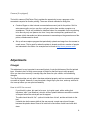
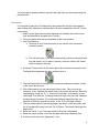
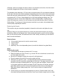
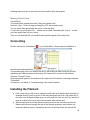
User Manual v016 Table of Contents Safety: PolyPrinter Operation Part Cleaning Computer Requirements Video CPU RAM Operating System System Specifications Parts of the PolyPrinter Main Components Front Switches Rear Panel: Camera (if equipped) Adjustments Z Height How to tell if it’s correct: Procedure: Adjustment: How to tell if the head is being pressed too hard into the bed: Z Tilt LeftRight Rarely Needed Adjustments: Maintenance Clearing Plastic from the Nozzle Oiling the Rods Adjusting Extruder Current Retaping the Bed Required Items: Procedure: Acetoning the Bed Nozzle problems Clogged Nozzle Wornout Nozzle How to measure the nozzle diameter Replacing the Nozzle Software Installation Power Saver Settings Computer Update Settings Computers with Extremely Slow Graphics Windows 8 Finding Parts Slicer Settings Kisslicer Slicing Parts NOTE: Steps Scaling Orientation Do the actual slicing Saving the GCODE Printing Multiple Different Parts Making a Bed of Parts Connecting Installing the Filament Trimming the Filament Feeding Filament Into the Extruder Closing the Filament Detector Ensuring the Filament is Ready Printing Your First Part Getting parts off the bed Procedure Always clean the bed off completely Common Tasks Changing The Filament Troubleshooting 2 Connection Problems Check the Port Problems and Solutions: Printing Stopped no messages Can’t Connect to Printer Parts are not sticking to the bed My small parts tend to get knocked loose during printing Tips Warranty Open Source Software 3 Safety: Your Acceptance of Responsibility: There are a number of potential dangers when using the PolyPrinter. In careful hands these do not normally present large risks. However, you must accept the responsibility of managing those risks yourself, and in turn so must you also be responsible for, or transfer responsibility to anyone else using or who has access to the machine. Do not use or purchase the Polyprinter without full acceptance of this responsibility. PolyPrinter Operation By its nature, the PolyPrinter must use some very hot components. ● The heated bed and its supports can be hotter than boiling water. Treat it with as much caution. ● The “hot end” where the plastic is melted is even hotter. It is in the range of a stove element. It WILL cause burns if contacted while hot. There are also potential problems of a chemical nature: ● Acetone, which is (optionally) used occasionally to clean the bed surface, is flammable and its vapor may be harmful. It must be used only on a cool bed, and never poured or spilled. The room must have adequate ventilation to disperse the vapors. Acetone on a heated bed will vaporize rapidly, forming an explosive mixture. ● The ABS or other plastics used for printing may give off fumes. In general these are not deemed very toxic but some people may develop a reaction after intense or long term exposure. ● Keep small children, the uninitiated, and anyone else not able to be safe, away from the PolyPrinter when its hood or side panels are open. Mechanical Dangers: The moving components of the PolyPrinter can hit, pinch and trap hands and fingers. Sometimes they can move surprisingly quickly, and with enough force to cause harm. Do not interfere with the moving parts. Be especially careful not to have a finger or hand become trapped between the head and the bed, since both can cause burns. Misuse, abuse: ● Do not use the PolyPrinter as a bird cage, reptile habitat, pet dryer, catstartler or anything else that could harm your pets. Using it to dry books, warm coffee, make cupcakes, and to dry insects is fine. ● Pets can be bothersome. Cats in particular recognize that the PolyPrinter is a 4 reasonablyempty box. Cats will also think the top of the PolyPrinter was designed to warm their feet and tummies. That’s OK. It has been specifically designed to take the occasional helpful feline’s weight, since, in fact, during development their presence and opinion was not optional. Part Cleaning ● Support removal is generally not too terribly difficult, but does depend entirely on the part, and the settings used for support. A good pair of small needlenose pliers with grippy serrations in the jaws can be used to tear away a great percentage of the support, most of the time. Using the pliers can be safer than using a knife. ● If using a knife, be sure to cut with the knife pressure in a direction away from body parts or anything precious a knife will very often shoot far past the cutting point when the plastic suddenly gives way. ● In general, it is best to have a good solid work surface to do parts cleaning upon. Protect it with a sheet of something durable but not precious, like a cutting board, cardboard, wood or a magazine. ● Try to orient the part being cleaned so that you are generally putting downward pressure on the tool, such that the desk surface takes all the force and is also what is hit by the tool when you cleave the plastic. ● Use finger guards or leather gloves to protect against minor nicks and cuts. ● Use tools that are just sharp enough to do the job. Sometimes a slightly duller tool will actually make support removal easier, because it does not dig into the plastic so much. Computer Requirements There are three main activities typically involved with using a 3D printer: ● Designing parts and preparing the 3D files ● Processing the files before printing (“Slicing”) ● Sending the files to the printer and printing them. Each has its own effect on the requirements the computer needs to meet. It is possible to use a relatively slow, older computer to do all of these things. It generally gets annoying to deal with a very slow computer though, so if you have a choice, and certainly if you have the budget to buy a new one, it is best to aim a higher than the minimum specifications. 5 Video A good video card or the newer Intel integrated video will give a nicer experience with most 3D design software, since it generally involves a need for rapid refreshing of the display. In addition, the software interface to the printer, Pronterface, updates a display of the printing process by default that takes up quite a bit of video performance, and can actually slow down printing and reduce print quality if on a computer with slow video, if not put into a mode (“Mini Mode”) where that drawing is suppressed. CPU The slicing programs e.g. Kisslicer will use all available processor cores to speed up the slicing process. An old singlecore machine like a Pentium 5, or a Centrino, will be much slower than a multicore chip like an Intel i7, which has eight effective cores. This is not too much of an issue for small parts, and is merely a question of the time you’d have to wait for the slicing process to complete. A generally useful price point is an i5. RAM The design programs and especially the slicing programs can use large amounts of memory to hold all of the 3D information when they process the files. Like the number of cores, this can be exchanged for time, but sometimes, and it is again much more of an issue with the larger parts, the amount of time required can rise dramatically, if the computer is bogged down moving information back and forth between hard drive and RAM because there is not enough RAM to work on it all at once. Aim for at least 6 GB if you are looking at a new computer. Operating System Windows Vista, Windows 7, Windows 8 (requires a few extra steps during installation). We only recommend considering 64bit versions. Apple Mac, Linux: Will work but no install package yet. Each software package must be separately installed. System Specifications Minimum: Intel Core Duo, 4 GB RAM, Intel integrated video Effects: Will need to use “Mini Mode” in Pronterface while printing. Kisslicer may issue warnings about RAM, and will be slow to slice files. 6 Useable: Intel i3 or i5, 6 GB+ RAM. There is a lot of variation in the video performance in this range, but if the computer is labeled as an “Entertainment” system it may be adequate. Better: Intel i7, 8+ GB RAM. If new, the video should be fine. Parts of the PolyPrinter ColorCoding: The mechanical parts that you might normally need to interact with are yellow. Main Components ● X Carriage travels left and right ● Y Carriage (Printer Bed) travels for and aft. ● Z Height Adjuster adjusts nozzle clearance to the bed for the first layer Front Switches At the lower left side there are two black switches. The top one controls the “Camera” light on the right side of the hood. (If equipped.) It’s good for general lighting of the printing area, and especially helpful in giving the camera enough light to work with, especially if you want to monitor printing progress remotely in a room where the lights have been turned off. The lower switch controls a light on the X Carriage to better be able to see printing in progress. On the side of the same switch housing is a red Reset switch. This will interrupt any operations in progress, cancel printing and disconnect communications. It is not normally needed or used as part of operations. It is occasionally needed if USB connections have been disturbed. Rear Panel: ● USB Connector ● Power Cord Connection ● Power Switch ○ You do not need to turn the PolyPrinter off when it is not being used. Leaving it on takes very little power, and maintains the USB connection so that it is able to print on demand. ● Fuse 7 Camera (if equipped) The builtin camera (PolyPrinter Plus) provides the opportunity to use a program on the connected computer to monitor printing. There are several methods for doing this: ● Create a Skype or other internet communication account just for the printer. Set it to autoanswer calls, and you can the n call your printer from another computer or a smartphone. This is only suitable for situations when it is acceptable for the monitoring to be done by only one person at a time. It may also create privacy problems if the camera (which has audio too) allows someone to eavesdrop on the general area of the printer, unbeknownst to others. ● Set up a framecapture program that periodically uploads an image from the camera to a web server. This is good for when the printer is shared such that a number of people are interested in the status. An example can be found at http://www.yawcam.com/ Adjustments Z Height This adjustment is very important to successful prints. It sets the thickness of the first printed layer. It needs to be in a fairly narrow range of height for that first layer to stick properly. Once you have it set correctly it usually stays the same for quite a while, until something changes. The PolyPrinter ships out only after it has been adjusted properly and has successfully printed a number of objects. However, it may have had a rough trip to your door, and may need a bit of a tuneup before you can print successfully. How to tell if it’s correct: If you think it is close, but want to be sure, try to print a part, with a setting that includes a “skirt” (see Kisslicer), which is a line of plastic laid down around the outside of the part before the actual part and its support. The skirt should be a bit “fat” quite a bit wider than it is tall, and be wellstuck to the bed. It should also be the same width all the way around, except near where it began, because the plastic doesn’t flow at full rate until a few inches of skirt have been laid down. 8 You’ll get used to spotting whether the skirt looks right, after you have been using the printer a while. Procedure: It is important to have the X Carriage all the way toward the left (the home position) when setting the Z adjustment, because there it is more independent of the Z Tilt (see next section). 1. Make sure the head has no plastic attached to the bottom face of the nozzle (use the Brass Brush included in the Tool Kit). 2. Clean any plastic from the bed, especially at the home position. 3. Use Pronterface to: a. Home the X axis. Press the button on the top left of the movement command circles. b. Turn off the motors. (If the printer has recently printed or moved its head they will remain “on” for about a minute.) Press the “Motors Off” button which is along the left side. 4. Press the Z Home button on the lower right of the movement command circles. The head should approach the bed, and may touch it. 5. The ideal height after Z Homing is zero clearance between the bottom surface of the nozzle and the bed. 6. With a little practice you can see a gap if there is one. Take a look at the clearance, if any, between the bottom face of the nozzle and the bed. Raise the nozzle slightly, using the “Z + .1” buttton in Pronterface, if necessary, to get a visible gap. Then slide the X Carriage toward the right, and see if the clearance remains roughly the same. If it is noticeably different toward the right, you should first follow the procedures below, in the “Z Tilt LeftRight” section. 7. Take an ordinary piece of photocopy paper, and slide it under the nozzle, with the X Carriage all the way to the left. Do a ZHome. The nozzle should grip the paper firmly. 8. Raise the nozzle .1 mm. The paper should still be just a bit gripped. 9. Raise the nozzle another .1mm and the paper should be completely free. 10. If that is not the case, see “Adjustment”, next. 9 Adjustment: The Z Height adjuster is the yellow knob on the left X Carriage, hiding behind the left aluminum vertical support. (It’s a little shy and does not like people watching it change.) If the head does not even grip the piece of paper at all, or completely lets go when raised .1 mm, turn the knob counterclockwise to reduce the clearance. If the paper is still gripped after raising a total of .2 mm, then increase the gap by raising the head, by turning the Z adjuster clockwise a little. One full turn is .5 mm, which is quite a lot. If it’s already very close, turn it much less than a turn 1/8th or ¼ turn at a time is a good starting point. Each time you turn it, again press the Z Home button, to let the printer find the new home position and let you see what difference the changed setting made. How to tell if the head is being pressed too hard into the bed: If the head is adjusted too low, you may get warning messages during printing, or just before it begins to print. If you are doing the “piece of paper” test described above, the paper will still be gripped a bit or a lot even after raising the nozzle .2 mm or more. 1. Move the X carriage or the Y carriage by hand (Motors Off) and see if the head leaves marks on the bed tape. It’s generally welladjusted if it just barely makes marks. If it’s tearing up the tape or digging into it at all, it’s definitely adjusted too low. Turn the knob clockwise to increase the clearance height, pressing Z Home with each change, and see whether it stops rubbing the bed so much. 2. Once you get it to where it seems close to correct, check the Z Tilt (below). Z Tilt LeftRight Your PolyPrinter should not require much attention to the leftright height adjustment. But if you think it has drifted off, or the whole X carriage assembly has been lifted off and the nuts disturbed, perform the checking procedure above, up to the point of “Adjustment:”. Since the Z Height detector switch is on the left side, we adjust the righthand motor to match the left. ● Press the “X Home” button on Pronterface. The X Carriage should go all the way to the left. ● Press the “Z Home” button. The nozzle should approach and just barely touch the bed. 10 ● ● ● ● It is OK if it has a small gap, for this procedure in fact, it makes this a little easier to perform, so if there is no gap at all, create a very small one now, by pressing the “+Z .1” button in the top half of the vertical set of buttons to the right of the main circular controls in Pronterface. Press it one or more times, enough to get a small visible gap between the nozzle and the bed. It doesn’t much matter what the size of the gap is, as long as it’s small enough for you to see whether it changes significantly, in the next steps. Press the "Motors Off" button on the left upper side of Pronterface. Also make sure that the Heater and “Off” button is pressed so you don’t get burned while doing this procedure. Then move the head to right manually and see whether the bottom of the nozzle moves away from or toward the bed as you move to the right. Perform the same “piece of paper” test on the right and left sides. What matters fist of all is that it grip it the same left and right, Use the “.01 mm “ to find a good height for this test. It doesn’t matter whether it’s correct overall, yet, as long as it’s the same left and right. When the clearance is the same left and right, go back and perform the overall height adjustment described above in “Adjustment”. To adjust it, you can make large changes by lifting the entire X carriage assembly until it becomes clear of the long nuts on the Z rods, and then spin the righthand Z nut: by one “flat”, or 1/6th of a turn at a time: Clockwise, to lower the head at the right and decrease the clearance. or Counterclockwise, to raise it and increase the clearance. Since that is just a coarse adjustment, you may find that you are not satisfied with either of the two “flats” that are closest to the correct setting. In that (rare) case, you will need to loosen the two setscrews that couple the right hand Z rod to the belt drive assembly at the top of the printer. Once you do that, you can make fine adjustments by slightly rotating the Z rods (most easily done down at the motor shaft). ● Twist the righthand threaded rod counterclockwise to decrease clearance ● Twist the righthand threaded rod counterclockwise to increase clearance After you have made any adjustments, slide head back and forth to check how the clearance changes. If you can’t see it change, your alignment is good. Rarely Needed Adjustments: ● X Belt Tension ● Y Belt Tension Each tension adjustment is an easy turn of the respective screw adjuster. Rightytighty. The belts should certainly have no slack at all, and should have enough tension to make a 11 noticeably quick vibration when “plucked”. ● A belt that is too loose will cause pairing of the diagonal fill, such that instead of evenly spaced lines, you will see two lines close together, a space, then two lines close, etc. ● Belts that are just a bit too loose can cause inaccurate corners edges that stick out a bit more than is acceptable for the given quality setting. It is normal for the belts to get slightly less tension after an initial number of hours of printing. You may need to adjust them once, perhaps twice, in the first months of operation. If you need to tension them repeatedly, please contact us at [email protected] ,. Maintenance Clearing Plastic from the Nozzle Sometimes oddsandends of plastic will accumulate on and around the nozzle. If left there, they will gradually harden into a black mess. It’s best to clear it away occasionally. The one thing to watch out for is the bottom surface of the nozzle, which has the tiny hole the plastic extrudes through. The nozzle is brass, which is quite soft compared with any steel utensil you might be tempted to use. Never allow a steel object to touch the bottom face of the nozzle. We have a Brass Brush in the toolkit so that you can more safely snag bits of plastic off the nozzle or bed safely (your and the nozzle’s safety). Oiling the Rods Apply a very small amount of light machine oil (e.g. Sewing Machine Oil) to the rods by soaking a QTip, or a small piece of folded cloth with the oil. Rub it on the rods to get just a very slight film. Adjusting Extruder Current This should not normally need to be done, but if you start using an unusual type of plastic, you may need to change the extruder drive current. Please contact us for detail on doing this. Retaping the Bed Required Items: ○ PET Tape ○ Knife or scissors for cutting the tape 12 ○ Plastic credit card, hotel key card or such to act as a squeegee Procedure: ● Raise the extruder at least 100 mm by using Pronterface (click on +Z 10 in Pronterface ten times). ● ● ● ● ● ● ● ● ● ● Make sure the bed heat is cool and the extruder heat is off you could get burned if the bed or the head is hot. Take off all of the old tape. Align the first piece with the front edge of the bed, tilting it so only that front edge is touching. When it’s line up right, take the credit card in one hand, keeping the tape tilted partly away from the bed with the other, and “squeegee” the cardhandend toward that edge of the bed. If it doesn’t lay completely flat (and it probably won’t especially when you’re still trying to learn how to do this), leave it alone temporarily. Now squeegee toward the hand still holding the tape, such that the card is at a bit of an angle and so is the line where the tape is being pushed down to the bed. Go all the way across and you can then let go of the tape. If the tape is not aligned well at all, just pick it back off the bed and try again. If it has wrinkles in it, you may need to use a fresh piece of tape. If it just has some bubbles in it, you can pick up one end, peel it back halfway, and use the card to push it back down to the bed while keeping the end up away from the bed, so there’s a clean line of contact. You may need to this for each half. When you’re satisfied with the first row of tape, do the same thing with the next, and continue on towards the back of the bed. Align one edge to the previous tape, keeping it taut. Tilt it so that only the near edge is making contact, and just barely. Don’t bother laying it down unless the edge is laying immediately beside and not on top of the previous tape. The rearmost section is probably most easily done through the side panel, with the bed slid partly back. Leave some extra tape to each side at first, in case you need to lift it and resqueegee it because of bubbles. It can be helpful to clean the freshlyapplied tape with Acetone (see next section), but it often works without doing that. Acetoning the Bed The PET tape on the bed will not be as effective if it becomes contaminated with oils from contact with fingers. The part lifter should normally allow contact to be avoided. 13 The tape also becomes less sticky when it gets scratched up due to many parts having been printed and lifted from it. Usually the end result is that the tape is worn out before acetoning it would be useful, so it is relatively rare to need to do this. However, if the tape is in good condition but not sticking (and if the Z height is correctly set) then you may find it useful to use Acetone to freshen it up: ● Fold a plain white paper towel over a number of times until it is around 2” x 3” more like a pad than a towel. Warning: some towels, like the blue “Shop Towels” partially dissolve and then leave a residue on the bed, preventing the plastic from sticking the opposite of what you’re trying to achieve. We have found the Kirkland plain white towels from Costco to work well, but other brands of plain white towels will probably also work well. ● Pour a little acetone on one corner so that it just soaks in and wets that end of the pad. Hold the pad by the other end to avoid getting the acetone on your fingers. Wipe the bed with the wet end, covering the entire surface. ● When you are done with it, take the paper towel to an outside garbage if you can, to avoid a buildup of the vapor in your work or living area. Nozzle problems You can expect to replace the print head extruder nozzle once in a while: ● It may clog ● It wears out, enlarging the orifice and reducing print quality. Clogged Nozzle If it is clogged, you will be unable to make plastic come out of the nozzle. This can happen (usually near the end of a large part, if Murphy’s Law is operating normally) while printing, and you will typically hear the extruder clunking for a while, then perhaps going silent. The bed and X Carriage will still be merrily traversing the part but no plastic will be coming out. (This is called “printing air”.) Sometimes before it fully clogs, it will partially clog, causing insufficient plastic to flow. If you have the head raised at least 30 mm and you extrude some plastic, it should normally fall straight down (unless it sticks to the head). If, however, it always curls up tightly and you cannot get it to extrude straight down, even when encouraged by snagging it with the brass brush and pulling on the end a bit, then the nozzle is partially clogged. Some plastics can go brown and very hard if left in a fulltemperature nozzle for an hour or 14 more. Usually this is not a problem. But if you can see some plastic oozing out when you apply manual pressure to the filament, or if you try extruding (when it clunks) and that plastic is markedly darker in color than it started out, it may have hardened up. If any will flow at all, you can, with sufficient patience, usually force the hardened plastic slowly out until fresh plastic replaces it. It may help to push a bit through, remove the filament, cut off the end, and push a bit more through, repeatedly. It’s still easier than changing the nozzle. Sometimes it can be unclogged by carefully isolating one of the wavy strands of brass wire from the brass brush, and with the nozzle at printing temperature, getting the wire up the nozzle opening and working it around and in and out (it helps to try to push some filament through at the same time you may need another person to do this more easily). Sometimes, though, it is just plain clogged and becomes useless. See “Replacing the Nozzle”, below. Wornout Nozzle How to tell if it needs replacement due to wearing too large: If you see a section of some of your prints where layer after layer (typically on the rightrear corner or wherever filament has begun to be laid down on the outside after travel) the plastic just doesn’t seem to fill in properly, consistently, and perhaps curls up in place on the outside, it may be due to the nozzle diameter. Failing to fill well is another indication. How to measure the nozzle diameter Fortunately, the plastic can help with this we don’t actually need to measure the size of the hole in the nozzle directly. Heat the head to e.g. 230 C, and extrude some plastic. Remove the plastic with the wire brush, gently. Wait a bit, and the nozzle will, as usual, slowly dribble a line of filament out. Snag it with the wire brush, after a couple of inches has dribbled out it’s best if there is a good straight section. Using a digital caliper, measure the diameter of this dribble, where it looks like it has a consistent diameter that represents the nominal diameter of the dribble. Be sure to use the wider part of the caliper jaws, not the very thin section at the tip of the caliper’s jaws. Rotate the dribble to see if it has some flatness to it, and take the average. (If it really has a lot 15 of flatness, where for example it’s twice as thick in one direction as the other, then the nozzle is probably clogged and will have to be cleaned or replaced.) The standard nozzle diameter of .35 mm seems to produce about .40 mm measured diameter for this test. We have seen distinct problems with printing when the nozzle is worn to the point where this test gives measurements of .60 mm. Slight problems can be seen sometimes with a measurement of .50 mm. It does depend a lot on just what settings are being used. The numbers given are for .25 mm layer height and .35 mm extrusion width. To keep using a nozzle that measures oversize, you can increase the track width (Kisslicer Style, Extrusion Width setting). This will give a bit less horizontal resolution in your prints, but probably better overall quality, especially the exterior. Replacing the Nozzle This requires using two wrenches (supplied) to loosen the old nozzle, and tighten the new one. Warning: Failing to use a second wrench to counter the nozzle wrench torque can result in loosening or failure of the filament tube. If after reading this section, you do not feel confident that you can do this yourself, find someone who is more “handy” and whom you can blame if there is trouble afterwards. Required Items: ● 13 mm wrench (openend is used to counter torque) ● 7 mm nut driver ● 1 Paper towel ● Optionally, one or two disposable gloves (to avoid skin irritation from glass fibers) Steps: Removing the nozzle ● Let the head and the bed cool down to 45 C or lower. ● Raise the head most of the Z travel, e.g. at least 150 mm so that there is room for the nut driver below the nozzle. ● Move the X Carriage to roughly the center of its leftright travel. ● Place the paper towel so that it covers the whole print bed. ● Whenever you move the “sock” the black siliconecovered insulator that wraps around the Hot End, small bits of glass fiber will fall down. The paper towel is to cover the bed in the hope of catching them all. They can cause skin irritation, so don’t lean on the paper towel during these next steps. Do NOT blow them off the bed, because glass fiber particles are much worse when breathed in than when just touching skin. Wipe with a damp, slightly soapy cloth. (You’ll need to acetone or retape the bed afterwards.) ● (Here’s where you need the head temperature to be low.) Push the black “sock” that surrounds the heated aluminum block (the “head”) up to make enough room to be able 16 ● ● ● ● ● ● ● to slide the 13 mm wrench onto it. You may need to pull it up on each corner in turn, because it tends to hang on the corners of the block. You may be able to maneuver the wrench in such a way as to get it on the hot end without raising the sock at all, by keeping the wrench at an angle, pointing the open end upward at an angle. At this point, you just need to make sure that you’ll be able to get the wrench on there during some later steps. An alternative is to pull the sock completely off., but this is generally more trouble, getting it back on, and it makes a bigger mess. The wrench doesn’t need to fully overlap the aluminum block it needs just enough overlap to firmly counteract the torque you’ll be applying to the nozzle. <NEEDS PICTURE> Clean any old hardened plastic from the nozzle itself. Sometimes it can build up quite a layer of accumulated plastic. But it tends to harden and become brittle, so it is often not too difficult to remove when cold. You will need the nozzle to be relatively free of this extra plastic, in order to put the wrench on it properly ( the circular or “box” end). Try it now, when the head is cold and you can clean it, before going on to the next steps where you’ll actually be using it. If you cannot clean it well enough to fit the wrench on while the head is cold, you’ll need to clean it with the brush while it’s hot. Once you are able to testfit the 13mm wrench onto the aluminum block and the 7 mm nut driver onto the nozzle, you must heat the head up to 200 C. (230, 240 are OK too, but using the minimum temperature that melts the plastic that may be in the threads is all that’s needed, and you may as well be dealing with the minimum temperatures so that your recovery time from the burns will be quicker.) Once the head is warm, clean the nozzle further if you were not able to clean it adequately before. The brass brush will usually work well. Watch out for flying bits of plastic or brass wires coming loose from the brush. Use safety goggles, or keep wel back, and only inspect when you’re not actively brushing. You should now be ready to actually remove the nozzle. It’s going to be hot, so again, make sure the paper towel is in place on the print bed, because if the nozzle drops the paper towel will prevent it from melting the tape where it lands. Here’s the one tricky and important part: ○ Slide the 13 mm open end wrench onto the aluminum block from the left. Slip the 7 mm nut driver onto the nozzle. (If you have a good feel for and experience with this type of thing, feel free to use different orientations.) <NEEDS PICTURE> ○ The purpose of the 13 mm wrench is to counter the twisting force on the aluminum block (and therefore the relatively delicate FIlament Tube) that will be applied to it through the effort of loosening the nozzle. All you need to do is keep it from trying to twist. You will therefore resist the nozzletwisting force with a matching force. ○ If you take a long time with these next steps, the wrench will become too hot to work with and you will need to remove it and wait for it to cool down before trying again. 17 ○ The nut driver on the nozzle needs to rotate with the near side traveling toward your left. Slowly apply a twisting torque on the nozzle. Match that twisting force using the 13mm wrench thumb pressing near the aluminum block, fingers pulling on the left end. ○ The nozzle should fairly easily break free and become easy to turn. At that point, you can remove the 13mm wrench, and also turn off the head heat. ○ Spin the 7 mm nut driver a few times to remove the nozzle. Just leave it in the end of the nut driver to cool down. Do not try to remove it until it has cooled down the nozzle will burn you if you try to grab it. Installing the new nozzle ● Make sure the head is at least 180 C, so any the plastic in the threads will be soft enough to give way. ○ Take the new nozzle, and insert it into the nut driver, with the threaded end exposed. ○ Put the nozzle’s threaded end up to the hole int he hot end, align it and center it. Spin it back and forth a bit to find the thread starting position. It should spin in a few turns easily by hand. If it becomes crooked and will not spin further, back it out and try again it may need a somewhat different starting orientation. ○ When you have spun it a few turns by hand, you can go on to the next step. ● Turn the head heat back on, to 200 C, so that the nozzle can be tightened properly in the case of plastic still being in the threads of the head. ● Place the 13 mm wrench back on the aluminum block, ready to counter the tightening torque you will be applying to the nozzle. ● Place the 7 mm wrench box end on the nozzle, and tighten it. (If wrench handle is to the right, then it goes way from you.) It should come close to the aluminum, and then stop wanting to go further. It takes a firm but not large amount of force on the wrench to tighten it so that it seals to the aluminum block. Remember to balance the torque you apy to the nozzle with countertorque on the 13 mm wrench. ● Let the head cool again, to 40C or below. ● Replace the “sock”. You will probably need to start it on all four corners and then pull it up on each corner in turn. It should hang a bit below the block but not as low as the nozzle. ● Carefully fold the paper towel up so as to capture all debris left by these operations, and dispose of it so that you do not spread the glass fibers around. The new nozzle may be slightly longer or shorter than the previous one. You will need to check the Z Height adjustment. Software Installation 18 Download the latest installation package from polyprinter.com or insert the DVD that came with the printer. Be sure to choose the correct 32 or 64bit package. (If in doubt, try the 64bit version, and it will warn you if it’s not the right one.) Follow the steps prompted by the software and be sure to run the serial port driver installation that should start up as the last step. You should have some new icons: ● Pronterface the program that controls the printer from your PC ● Kisslicer our preferred slicer ● NetFabb used to rotate parts, fix up problems with them ● Slic3r an alternate slicer, sometimes better for art pieces, and for setting up a bed of different parts. Power Saver Settings It is very important that the computer not go “to sleep” during printing, while Pronterface is sending commands to the printer. If that happens, often the USB connection will be dropped, and the print in progress will fail, and be unable to be continued. You can set up a custom power setting for printing, if you wish. You’ll want Hibernation to be Never, and Sleep to be Never. It’s OK for the hard drive to shut down, and for the CPU to use powersaving modes. Computer Update Settings Set Automatic Updates to require your approval before installation and especially rebooting. Computers with Extremely Slow Graphics A few of the slower laptops we’ve seen have such slow graphics chips that the drawing that Pronterface does is actually slowed down so much that printing speed is reduced. If the printer seems sluggish, stopping briefly or going halfspeed at times during a print, you may need to use “MiniMode” which closes most of the Pronterface window. That button will change to Full Mode so you can open it up fully again to check progress or start another print. Windows 8 There is a problem installing the standard USB driver under Windows 8. You need to turn off a new "feature" in Win8: From the Metro Start Screen, open Settings (move your mouse to the bottomrightcorner of the screen and wait for the popout bar to appear, then click the Gear icon). 19 Click More PC Settings. Click General. Scroll down, and click Restart now under Advanced Startup. Wait a bit. Click Troubleshoot. Click Advanced Options Click Windows Startup Settings. Click Restart. When your computer restarts, select "Disable driver signature enforcement" from the list. You can now load your modified driver. Reboot again once the driver is installed and all will be well. References: ■ http://www.windows7hacker.com/index.php/2012/08/howtoinstallanu nsigned3rdpartydriverinwindows8/ ■ http://www.pjrc.com/teensy/windows8.txt Finding Parts The installation will have created a small samples folder under the main install folder (e.g. C:\Program FIles\PolyPrinter\Samples). 1. Get the STL file into a folder accessible (local HD, USB stick, LAN drive) to the local machine. ● Download from www.thingiverse.com which contains tens of thousands of potentially printable parts (and lots of other buildable items). ● Alibre, 123D, Sketchup etc. CAD program export ● Meshlab, Blender etc. 2. Check the file for oddities. Lots of STL files have reversed triangles and other problems. Load the file into NetFabb. If it’s all greencolored, it’s fine. Red areas will probably not be sliced correctly. NetFabb will help you fix them up, but that’s beyond the scope of this quick guide. Use Part, Add from the menu. 3. Make sure the orientation is the best for printing. Many STLs are oriented to make their designing convenient, but that is not necessarily the best way to print it. There are two important aspects to the orientation: 1. Amount of support required. This affects printing time, cleaning time, and surface finish. 2. Strength. Printed parts are stronger within the layers than between layers. Try to orient the part so that the biggest, flattest surface is touching the bed. Look for 20 overhangs any part of the object that sticks out horizontally, or whose underside slopes down will need support. In Netfabb, rotation around any of the X, Y, or Z axes is easy. Select Part, Rotate from the menu or use the tool bar button, or use CTRLR. Select the angle (usually 90 or 270) and the axis, and press the Rotate button. When you have the object rotated the intended way, use Part, Export Part and Save as STL. Save it under a different name so you can keep the original e.g. if the original name was “xxxxx.stl”, save it as “xxxx rot.stl”. Slicer Settings We could probably write a small book about the slicing settings. Plastic, print choices, parts, all kinds of things can make you try different settings. Here are the basics: Kisslicer X,Y Travel Speed 250 mm/sec Printing: High Quality Setting: Perimeter: 40 mm/sec Solid Infill: 80 mm/sec Sparse Infill: 80 mm/sec Draft Mode Lower Quality: Perimeter: 250 mm/sec Solid Infill: 250 mm/sec Sparse Infill: 140 mm/sec Slicing Parts NOTE: The software installation actually installs two popular programs for slicing – Kisslicer and Slic3r. These programs create GCODE from STL files. ∙ We at Polyprinter much prefer the use of Kisslicer over Slic3r. But either can be used 21 for slicing the file for a Polyprinter print. ∙ The control program, Pronterface, can read either STL files or GCODE files. If a STL file is read, then Pronterface has built in functionality to call Slic3r to create the GCODE file before printing the file. The “Settings” menu lets you set up Slic3r but it’s tricky to get those settings to work when just opening an STL file. The usual steps, for printing a file using Kisslicer are: ● Open the STL file in Kisslicer. ● Slice the file and save it. This saves the GCODE file in the same directory as the STL file. Kisslicer will use the settings from the tabs in the bottom right corner of its main window. ● Open the file in Pronterface. Make sure you open the *.GCODE and not the *.STL file. ● Print the file. If instead you accidentally open the STL in Pronterface (instead of a GCODE file produced by Kisslicer) then you will probably not get what you expect. For most things, use: Style Tab: Style: Mechanical Support Tab: Support: Normal Material Tab: Material: ABS Printer Tab: Printer: PolyPrinter Slider on right: Precision: Fast ■ When you just want to see what it's like, use full speed. When you're printing a "keeper", you will want to slow it down. ■ For some parts, it won't make much difference, because it has to slow down on the interior fill, and for small things with lots of layers it slows down and turns on the fan to avoid making it all melty. Precise ■ Use this if you want the best finish and accuracy. ○ You can adjust the Precision slider from 0 to 100 % Precision. 50% is a good place to start, if you are not sure. You can see Kisslicer’s time estimate vary, if you have already sliced the object once. For scaling, look at the menu up top, "All Models" Inch>mm is a shortcut to 25.4 conversion As a general rule, if you print with no support, and have steep overhangs, you should also change the Style to have "Loops go from Inside to Perimeter" checked. It will do much better on overhangs. Objects with irregular bottoms, thing contact with the bed, or other things that prevent good 22 adherence to the bed may need a Raft. When printing challenging parts with no support, you may need to use support up to a certain level to ensure good initial adherence and accuracy of any bottom curvatures. The free version of Kisslicer will not allow loading more than one STL at a time, so to load a new STL you must press the “X” on the small window along the right side, to remove the old one. See “Printing Multiple Different Parts” The first time you print a particular part that you may want more than one of, print just a single one, if there is any doubt about the settings being correct. Steps Get the STL file into a folder accessible (local HD, USB stick, LAN drive) to the local machine. The free version of Kisslicer will not allow loading more than one STL at a time, so to load a new STL you must press the “X” on the small window along the right side, to remove the old one. Press “Open”, and find the STL file for the part you wish to print, and press “Open” to load it. The part should appear in the main window. Check the file for oddities. Lots of STL files have reversed triangles and other problems. If it’s all greencolored, it’s fine. Red areas will probably not be sliced correctly. NetFabb will help you fix them up, but that’s beyond the scope of this manual at this time. Scaling If it is surprisingly tiny, it may have been designed in Inches. Kisslicer has a quick Inchtomm scaling conversion for that. See the menu, All Models/Inch → mm. You can adjust the size of the model to something you think is appropriate by typing over the “Height” field in the model’s thumbnail window on the righthand side. You can also use the menu, All Models/Scale By X function. Orientation Make sure the orientation is the best for printing. Many STLs are oriented to make their designing convenient, but that is not necessarily the best way to print it. There are two important aspects to the orientation: ○ Amount of support required. This affects printing time, cleaning time, and surface finish. 23 ○ Strength. Printed parts are stronger within the layers than between layers. Try to orient the part so that the biggest, flattest surface is touching the bed. Look for overhangs any part of the object that sticks out horizontally, or whose underside slopes down will need support. Kisslicer has a few basic rotation features. Right click on the thumbnail window and you will get a menu. Hover over “Transform Axes” and a submenu will appear. Slide over to it and you can select from several rotation options. Experiment with them. Do the actual slicing Press “Slice”. For large models this can take quite a while. You can see the progress in the graphics window. When it has sliced, there will be a time estimate on the lower right. You can easily scale the model by typing in a new height in the Upper righthand window with the thumbnail of the part. Just type over the height. You can also rotate it on the bed. Saving the GCODE Once you are happy with all your settings (you may need to reslice, if the time estimate has disappeared), then you can Save. After you have approved the output file name (which normally needs no changes) a black text window will appear for a short while, as a postprocessing script runs that improves the print quality a bit. When that window disappears, the GCODE file is ready to be loaded into Pronterface. Printing Multiple Different Parts The “Pro” version of Kisslicer ($42) allows loading many different parts onto the bed to print them in one batch. If you do not want to spend that money, you can still create a bedful of dissimilar parts, using the “Slic3r” program that is included in the PolyPrinter install package (yellow icon). NOTE: Slic3r is not set up to actually slice models and create correct gcode for the PolyPrinter by default. We are waiting for a reliable version before recommending that it be used for creating gcode. However, it does a good job of loading parts onto a bed and 24 exporting them as a set, so we include it in the install for only that purpose. Making a Bed of Parts Launch Slic3r. You should see a gridded panel with “Drag your objects here/”. Press the “Add...” button or drag and drop your STL files onto the panel. You can move them around with the mouse click and drag. To save the set, use “Export STL...” and be sure to name it something like “Set of...” so that you know what it was you put in there. Then you can load that STL into Kisslicer and create the gcode for the whole set. Connecting Find the red icon for “Pronterface” , in your Start Menu. Click to launch Pronterface. It should look something like this: The important part is the Port. Most of the time, it will already be filled in with the port that represents the USB connection to the printer. We’ll assume it’s correct for the moment. Press the “Connect” button. Some text should appear in the window on the right side of Pronterface, including the phrase: “Connected”. If it does not:, see below, in Troubleshooting, Connection Problems. Installing the Filament ● If it’s a new reel you will have to unpack it and find the end, (which should normally be threaded through a hole in the rim of the reel) taking care not to let it slip under any of the other turns of filament. Make sure you can loosen the end, but don’t let it unravel. If there is no hole in the rim to secure the end with, hold onto the end. ● While securing the end of the filament, slip the reel over the reel mount so that the filament will come up through the hole in the filament guide arm, and continue up toward the filament pulley. Viewed from the front of the PolyPrinter, the end will be 25 pointing upwards and will be on the left side of the reel, where it needs to go through the hole in the black filament guide arm. Feed it through that hole, and bring it forward toward the extruder. ● You don’t need to put it over the pulley until you have fed it into the extruder, although you may do so. Trimming the Filament ● If the end of the filament is irregular, bent or blobbed, then you must trim it using the handy filament cutter that is mounted on the upper cross bar. Swipe the filament through the gap in the cutter, holding both sides. Feeding Filament Into the Extruder ● Press down firmly on the left end of the yellow lever, so that it goes down, which moves the drive pressure ball bearing away from the filament drive wheel and lets the flament past. Push the filament down through the hole in the top of the lever, and ensure that it goes all the way down and into the filament tube that is just below the drive wheel. It should go into the tube at least an inch. ● Push the filament, still holding the lever down, until it won’t easily go any further. It should go in about two inches (5 cm), and if the head is up to temperature, continued steady pressure will make melted filament ooze out of the nozzle. ● Let go of the lever. Closing the Filament Detector ● Hook the filament over the pulley and move the pulley and filament together up toward the switch. ● Its magnets should pull it into position with a firm click. ● Pronterface should display “Filament OK”. Ensuring the Filament is Ready ● Using Pronterface, set the head temperature to 230 C (ABS). That’s as hot as a stovetop element. It will cause severe burns if you touch it, even momentarily. ● You can also set the bed warming to 110 C if you want to cut a little waiting time off the print. The bed gets hot enough to boil water. Don’t touch it! ● Click the checkbox in Pronterface labeled “Monitor Printer”. It will start updating the temperature displays every few seconds. ● Once the head is up to temperature, press the “Extrude” button. The filament drive gear should turn with a little hum, some filament should be drawn into the extruder, and a bit of plastic may come out of the nozzle. 26 ● Press the button a few more times, and soon there should be plastic coming out of the nozzle each time. If there is not, make sure that the end of the filament has actually gone down inside the filament tube If the end is curled, you may need to straighten it, cut it, (easy to do with the Filament Cutter) or flex and twist it around a bit to get the end into the filament tube. Printing Your First Part ● Press “Load File” in Pronterface, Find the “samples” folder under your software installation and choose the “Calib Steps and Hole.gcode” file. ● Press “Print”. It will move the carriages a little, and then it will wait until the bed has headed up fully. This can take up to 13 minutes, depending on room temperature. You should see the temperature display climbing up to 110 C as it heats up. The Pronterface log window will show a new line every second or show, as it get updated temperatures while waiting. ● Once the bed has heated up fully, the carriage will again move a bit, pause for a few seconds, and then printing should begin. Getting parts off the bed A good general procedure is to watch Pronterface for the bed temperature to drop about 65 C and only then try to release the part. The bed will cool down fastest if the hood is opened and the Y carriage is pulled forward all the way. Parts remain bendable until they have cooled down below about 70 C, so you risk deforming them if you try to slowly peel or pry them off above that temperature. If you let the bed cool down down even further, to 30 C, some parts (the larger ones, especially) often just come loose enough to pull easily off the bed. Procedure ● Use a knife with curved blade, a sharp scraper, or, if you have the PolyPrinter toolkit, the included separator tool, which can be slid flat under the part. ● Get the curved part of the blade to hook under or into one corner of the part, without digging into the tape. ● Twist the knife to cause upward force. Do NOT push the blade into the part or under it. Make the twist or an upward force do the work such that the blade cannot suddenly shoot in its cutting direction and injure you. You should use a blade that is on the dull 27 side to reduce the chance of such an injury. Parts will tend to almost instantaneously go from being very stuck to completely free. Always clean the bed off completely ● Make sure you clean all the plastic off the bed before starting any print. Check the home corner too. But don’t use your hands or fingers, you could burn yourself, as well as get oils on the bed and then the plastic will not stick there. ● You can often use the part you just took off (if it’s not too hot to hold) to scrape off the outer ring of plastic that was laid down around it (the “skirt”). Common Tasks Changing The Filament Heat the head to at least 230 C. Push down on the left side of the extruder lever to release the pressure on the filament. Pull up on the filament. The very tip of the removed filament can burn you watch out. If it does not want to come out, and you have only just heated the head up, wait a minute or so for the heat to fully warm the filament. You may set the head temperature to 260 C if necessary, for a very stubborn one. Once you have the filament out of the extruder, hold onto it and remove the spool with your other hand, and insert the free end into one of the holes in the rim of the spool, if there are any. (And if there are not, make at least one.) This will ensure that the filament doesn’t become looped under itself or fall loose. Inserting the new filament is done as described above, in Installing the Filament Troubleshooting Connection Problems Check the Port Open Device Manager, and look at the “Ports (COM & LPT)”. It should list “USB Serial... COMxx). Make sure Pronterface has that port selected. You may need to press the Port button on Pronterface, or restart Pronterface to get the correct port number to appear. Try pressing the Reset button <DIAGRAM/PHOTO>, then press Connect again. 28 ● If you see “M104” then the serial port is incorrect. Check the dropdown box and select any alternate port it has there. You may need to go to the WIndows Device Manager and see what serial ports are listed. it will likely be the only one listed. ● If you do have the correct port, and nothing happens, open the front cover, and press the red Reset button on the Polyprinter, and then try the “Connect again”. ● If still nothing happens, disconnect the USB cable, open the front cover, and press the red Reset button on the Polyprinter, reconnect the USB cable, and then try the “Connect again”. ● if it still fails... Restart Pronterface, try another USB port, turn off printer.... check nut switch. If it says “Connected...” you are all set. Try making the carriage move to make sure. 29 Problems and Solutions: Printing Stopped “Check Filament” Look for a problem with the filament binding up on the roll, or having run out. Clear up the problem, close the filament switch, and printing should resume. Printing Stopped no messages If this happens to any print, it's really helpful to do <ALT>PrtScn on Pronterface at the time, paste the screenshot into MS Paint, and then send that plus the STL and the exact GCODE being printed, to [email protected] for diagnosis. As well, it's good to know whether the printer is responsive through direct commands with Pronterface e.g. raising the head a bit. Can’t Connect to Printer If using Pronterface, hit "Disconnect" first. Then hit the red reset button on the lower left side of the switch housing that's in front of the left vertical aluminum bar. Then hit "Connect" on Pronterface. You may need to check the serial port. The best way (on Windows) is to fire up Device Manager and see which port is coming and going when you press and release the Reset button. Then Make sure that's what Pronterface is trying to connect with. You can type in the COM port field. Parts are not sticking to the bed ● Ensure that the Z height is correct, and that it is level lefttoright. ● If the bed tape is scratched up, it may be time to change the tape. ● If people have touched the bed very much, it will get finger oils on it and the parts will not stick well. ● You can sometimes freshen the bed up with acetone. ● You can simply retape the bed instead of using acetone. ● Some parts simply don’t have enough area on the bottom layer to stick well. Use a Raft support setting, or add a brim or “mouse Ears” (see below) to the design. My small parts tend to get knocked loose during printing First, see above for parts not sticking in general. But if all of that is in order: 30 Try using the Support tab, Raft “Grid” setting, using some “Inflate Raft” of e.g. 4 mm, which will provide an area under the part that will attach more firmly to the bed. If it is a part you have designed, you can add one or two semicircles of one layer thickness to opposite corners (for example) to provide some additional area. These “mouse ears” are easy to peel off after printing. This also helps prevent corners peeling up, if the ears are made large enough. Tips You can make your own glue by dissolving some scrap filament in some acetone. The ABS thickens it up a bit (you decide how thick) and that lets it stay in place and fill in gaps a bit. Acetone all by itself works well too, if the parts fit closely together. Brush it on both, push, hold, and they just melt together. Any type of "krazy" glue, Cyanoacrylate, works well too (but can make a white film that shows up on dark or clear parts). For strong yet flexible bonds, one of the"goop" type products will work well e.g. Automotive GOOP. Kiwi ShoePatch is the best. 31 32 Warranty We want all PolyPrinter owners to be happy with their purchase. We feel that including a reasonableduration parts warranty is one thing that can help. We want to be responsible for providing a machine that operates as it was intended and designed to do. For a period of 6 months after a new PolyPrinter has been unpacked and begun to be set up, PolyPrinter will send replacement parts free of charge, if the part was found to be defective. Polyprinter will pay shipping both ways for such parts. Unfortunately it is not economical to provide onsite labor to install replacement parts, and shipping the entire PolyPrinter is very expensive. Therefore, this warranty is offered with the understanding that the customer must be prepared to install parts, or find someone local to do so. We will gladly try to assist with advice or instruction in replacing the parts. The entire PolyPrinter can be disassembled and reassembled with hand tools. If you prefer to have PolyPrinter perform the labor, then you may send your machine to us at your expense (both ways) and we will do the repair, with no labor charge. Alternatively, at our discretion, we may deem that there is some reason why the printer must be returned to PolyPrinter for repair. (This is why it is important to keep the box and all packing materials somewhere.) We will in that case pay for shipping in both directions as part of the warranty. Continuous Improvement vs New Models and Versions We intend that the PolyPrinter will be continually evolving. We intend to keep improving it in minor and major ways for a long time. Each PolyPrinter represents the “state of the art” at the time it was manufactured. The existence of newer PolyPrinters with improvements does not by itself imply that your PolyPrinter has a defect that must be covered by the warranty. The warranty only covers things that were not manufactured correctly or could not fulfil their intended function to the degree they were specified to at the time. That being said, however, this does not preclude us from offering customers the ability to selfupgrade their machines by printing replacement parts or purchasing updated replacement parts to keep their machines up to date. We will be happy to assist in this process with information and advice so that all our customers can have the best practical machines. We intend to also have generational changes that may represent a new starting point, such that improvement will no longer be made to a given model. That is a normal part of a product 33 development cycle. We therefore cannot predict for how long we will improve a particular generation in a manner that is compatible with existing PolyPrinters. More Formally: The PolyPrinter has a 6Month “carryin” warranty. The warranty covers: ● failures due to defects in manufacturing ● design problems preventing functionality promised to at the time of purchase ● twoway shipping of replacement parts ● labor at a designated repair facility ● forum, email, and live telephone support for diagnosis and repair ● breakage or wearing out of vital things that are not nominally wear items: ○ bearings ○ rods ○ belts ○ heaters ○ electronics ○ printed bits ○ wiring ○ fans It does not cover: ● Obsolescence ● Mistreatment ● Consumables or wear items. (e.g. bed tape, nozzles.) ● Shipping the entire printer ● Cosmetics ● Damage ● onsite labor 34 Open Source Software The PolyPrinter comes with several opensource packages. The installation puts the license files in place at the time. Access to source code is available upon request. The Gcode M115 gives information on the open source software that is part of the PolyPrinter itself. 35