1
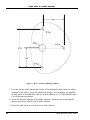
CATTRON GROUP INTERNATIONAL
PUMP BOSS II ®
RADIO CONTROL SYSTEMS
USER’S MANUAL
PBII Series
Issue Number 1, May 2006
WARNING!
AVERTISSEMENT!
Read all safety rules and
warnings before installing and
operating this system.
Lire toutes les consignes de
sécurité et tous les
avertissements avant de faire
fonctionner ce systéme.
http://www.remtron.com
1916 W. Mission Road, Escondido, CA 92029-1114 • Ph: 800-328-5570 • Fax: 760-737-7810
Issue Number 1, May 2006
PUMP BOSS II® USER’S MANUAL
REMTRON, INC.
PUMP BOSS II® RECEIVERS
FCC COMPLIANCE STATEMENT
PUMP BOSS II® series receivers have been tested and found to comply with the limits for
a Class B digital device, pursuant to Part 15 of the FCC Rules. These limits are designed
to provide reasonable protection against harmful interference in a residential installation.
This equipment generates, uses, and can radiate radio-frequency energy, and if not
installed and used in accordance with the user manual, may cause harmful interference to
radio communications. However, there is no guarantee that harmful interference will not
occur in a particular installation.
If this equipment does cause harmful interference to radio or television reception, which
can be determined by switching this equipment on and off, the user is encouraged to try to
correct the interference by one or more of the following measures:
• Reorient or relocate the receiving antenna that is connected to the device that is
receiving the interference.
• Increase the separation between our equipment and the equipment that is receiving
the interference.
• Consult our factory or one of our Service Representatives for additional help.
Responsible Party:
Remtron Inc.
1916 W. Mission Rd.
Escondido, CA 92029
Phone:
800 328-5570
760 737-7800
Issue Number 1, May 2006
i
PUMP BOSS II® USER’S MANUAL
This page intentionally left blank
ii
Issue Number 1, May 2006
PUMP BOSS II® USER’S MANUAL
TABLE OF CONTENTS
SYSTEM DESCRIPTION ...................................................................................... 1
PBIIT Transmitter .............................................................................................. 2
PBIIR Receiver .................................................................................................. 4
INSTALLATION ................................................................................................... 6
Mechanical ........................................................................................................ 6
Antenna Installation ........................................................................................... 7
Locating the Antenna ......................................................................................... 7
RCA7 Long Range Antenna .............................................................................. 7
Installation Procedure ................................................................................... 7
Optional Antenna Mount ................................................................................... 9
Installation Procedure ................................................................................... 9
WIRING INSTRUCTIONS .................................................................................. 10
USING YOUR SYSTEM ..................................................................................... 15
Starting the System ........................................................................................... 15
Pump Operation ............................................................................................... 16
Helpful Hints ................................................................................................... 17
System Troubleshooting .................................................................................. 18
System Does Not Operate ........................................................................... 18
Insufficient Range ....................................................................................... 18
Transmitter Troubleshooting ....................................................................... 19
REPLACING THE BATTERIES .......................................................................... 20
REPLACING THE TRANSMITTER ................................................................... 21
AUTO LINK™ Procedure ................................................................................ 21
REPLACEMENT PARTS .................................................................................... 23
Pump Boss II® Spare Parts List ........................................................................ 23
WARRANTY STATEMENT ............................................................................... 24
Issue Number 1, May 2006
iii
PUMP BOSS II® USER’S MANUAL
LIST OF ILLUSTRATIONS
Figure 1. PBIIT Transmitter .................................................................................. 3
Figure 2. PBIIR Receiver ....................................................................................... 4
Figure 3. RCA7 Antenna Mounting Template ....................................................... 8
Figure 4. Optional Antenna Mount ........................................................................ 9
Figure 5. Changing The Batteries ......................................................................... 20
Figure 6. AUTO LINK™ Switching ...................................................................... 22
iv
Issue Number 1, May 2006
PUMP BOSS II® USER’S MANUAL
SAFETY RULES
WARNING!
READ ALL INSTRUCTIONS
Failure to follow these rules can result in serious personal injury.
INSTALLATION
•
PROVIDE A SAFETY CUTOFF SWITCH. If maintenance is required, the radio must be
disconnected from power to prevent accidental pump activation.
•
USE PROPER WIRING. Loose or frayed wires can cause accidental pump activation.
•
DO NOT INSTALL IN HOT AREAS. This apparatus can be damaged by heat in excess
of 160° F.
•
DO NOT INSTALL IN HIGH VIBRATION AREAS. The life of this apparatus might be
shortened through long exposure to intense shaking or vibration.
PERSONAL SAFETY
•
MAKE SURE MACHINERY IS CLEAR BEFORE OPERATING. Do not activate the
remote system unless it is safe to do so.
•
TURN OFF THE RECEIVER POWER BEFORE WORKING ON MACHINERY. Always
disconnect the remote system power before doing any maintenance to prevent
accidental operation of the machine.
Issue Number 1, May 2006
v
PUMP BOSS II® USER’S MANUAL
This page intentionally left blank
vi
Issue Number 1, May 2006
PUMP BOSS II® USER’S MANUAL
SYSTEM DESCRIPTION
The Pump Boss II® system consists of a handheld transmitter, a pump mounted receiver, and
antenna.
When the operator presses a switch on the transmitter, a digital message is sent via radio
waves to the receiver. The digital message contains one of millions of possible ID Codes.
This unique code makes it possible for the receiver to respond only to the proper transmitter.
Additional codes are also sent that make the chance of false commands less than 1 in 16
Million.
The Pump Boss II® system incorporates a fail-safe ‘STOP’ feature in that a loss of radio
signal will drop all relays in 5-seconds, thus shutting down the pump. When radio
communications have been restored, the link to the receiver is restored and the user can
command any function. During the loss of signal the receiver defaults to all functions off,
and the user must restore any latching functions that were reset by loss of signal.
All Pump Boss II® systems incorporate the innovative ‘AUTO LINK™’ function that allows
the receiver to ‘learn’ the frequency channel and address of a replacement or spare
transmitter. This function allows the Pump Operator to quickly substitute a spare PBIIT
transmitter in the field without the need to physically reconfigure its frequency channel and
address to match that of the receiver.
Receiver Relays are Poly fused at 4.5-Amps. If too much current is drawn through these
relays, the Poly fuse will open and remain open as long as electricity is applied through the
relay. Once electricity is removed, the fuse will heal itself and be ready to operate in about
1-minute.
NOTE
In units that are operated above 24 VDC the relays are
protected with a 7-Amp fuse. Such fuses can only be
replaced at the REMTRON® factory.
The Pump Boss II® system complies with the requirements for operation under Part 15 of
the FCC rules and regulations. This means that neither the operator nor the company need
apply or register for a license to operate this equipment.
NOTE
Any metallic objects will affect radio waves. As the
result, difficulty operating in certain locations may be
encountered. Read the section on using your system so
that you can get the best performance from your system.
Issue Number 1, May 2006
1
PUMP BOSS II® USER’S MANUAL
PBIIT Transmitter
Pump Boss II® transmitters are housed in a molded polymer plastic IP 67 compliant case,
that stands up to extremely rugged use. A key feature is the REMTRON® patented switch
assembly for control inputs. This long-life elastomeric keypad is ergonomically designed to
provide easy operation over long periods of time with exceptional reliability. A leather
holster provides added protection and convenience. An optional clear protective pouch is
available from your dealer.
Pump Boss II® transmitters are designed to be very efficient, operating from two AA
batteries. To ensure long battery life, the transmitters will shut themselves off after one hour
of inactivity. The antenna is internal to the transmitter case, protecting it from damage. A
bi-colored self-test LED indicator provides a quick visual check of transmitter and battery
status. This LED flashes GREEN when no problems are present, flashes RED and GREEN
under low battery conditions, or SOLID RED when other problems are encountered.
Referring to Figure 1 below, the Pump Boss II® Transmitter incorporates a POWER ‘ON’
Pushbutton, a ‘STOP/OFF’ Pushbutton, and a ‘PUMP/OFF’ 2-position Rocker Switch.
Additional rocker switch functions are also provided, as follows:
• ‘FWD/REV’
• THROTTLE ‘INCREASE/DECREASE’
• VOLUME ‘INCREASE/DECREASE’
NOTE
2
Depending on your exact system configuration,
some or all of the additional rocker switch functions
may not be operational.
Issue Number 1, May 2006
PUMP BOSS II® USER’S MANUAL
Figure 1. PBIIT Transmitter
Issue Number 1, May 2006
3
PUMP BOSS II® USER’S MANUAL
PBIIR Receiver
Referring to Figure 2 below, Pump Boss II® Receivers are housed in a IP 67 Compliant,
watertight molded polymer plastic case that stands up to extremely rugged use. Electrical
connections to the receiver are made through a multi-conductor cable. The cable plug from
the external antenna is connected to a TNC socket on the underside of the Receiver.
The AUTO LINK™ Touch Pad switch allows the receiver to learn the ID code from a
Remtron replacement transmitter. See the AUTO LINK™ section on page 21 of this
manual for more information.
Figure 2. PBIIR Receiver
4
Issue Number 1, May 2006
PUMP BOSS II® USER’S MANUAL
PBIIR Receivers use an advanced synthesized FM receiver designed to work in the presence
of potential interfering signals such as those that might be encountered from pagers, cell
phones, two-way radios, etc.
A microprocessor-based decoder ensures a great deal of safety as well as versatility.
Commands are received on one of 81 possible frequencies and are both checked against a
16-bit address code for proper identity and further tested against a 16-bit CRC check code.
This ensures that only valid information meant only for the particular unit is decoded. The
receiver assembly monitors and indicates its status on a continuous basis. The diagnostics
are presented in a simple, easy to understand format.
The ‘POWER’ LED illuminates when power is applied to the receiver.
The ‘SIGNAL’ LED has three functions:
• It will double flash, pause and then repeat indicating the receiver is looking for a
signal.
• It will flash at a slow rate when receiving a signal, a faster rate when a command is
received.
• It will remain on with two short blink periods when the AUTO LINK™ switch is
pressed on the receiver. After the receiver has learned the channel and address of the
replacement transmitter, the LED will remain on solid without the two blinks.
The ‘OUTPUT’ LED illuminates when the transmitter activates a command function (a
receiver relay is activated).
Issue Number 1, May 2006
5
PUMP BOSS II® USER’S MANUAL
INSTALLATION
NOTE
Pump machines will vary between different
manufacturers; therefore some wiring connections
may be different from those provided in this manual.
If you have questions about your installation, call
Remtron Customer Service for assistance. Please
have the Engineering Number (ENG #) beginning
with 982 on the back of the transmitter label
available when calling the factory.
Product Wiring Configuration Sheets for the most common Pump Boss II® systems are
provided on pages 11 thru 14 of this manual.
WARNING!
Do not install the receiver near exhaust pipes or in
other hot areas.
The Pump Boss II® system consists of:
•
•
•
•
Handheld transmitter
Leather transmitter holder and strap
Receiver with attached multi-wire cable
Antenna with coaxial cable
Mechanical
In selecting a place to mount the receiver consider the following points:
•
Access to the wiring for the control box on your machine.
• Protection from mechanical damage during towing or during use.
• Select a location with a flat mounting surface.
• If possible, protect the receiver from direct exposure to sun and rain. Even though the
receiver is weather resistant, it is good practice to protect it from the elements.
Securely mount the receiver box to the pump using the supplied hardware.
6
Issue Number 1, May 2006
PUMP BOSS II® USER’S MANUAL
Antenna Installation
NOTE
Proper antenna installation is essential for peak
performance of the Pump Boss II®. Take care to
install the antenna properly.
Two different styles of antenna are available for Pump Boss II® systems. These must be
permanently attached to the pump for proper performance. The standard Antenna supplied
with the system is the RCA7 Long Range Antenna. An optional Antenna Mount is available
that accepts a ‘whip’ style of antenna for short-range applications.
Locating the Antenna
For best reception, the antenna must be mounted to a horizontal surface with the top of the
antenna at least 8-inches away from all major metal structures (vents, splash panel, exhaust,
etc). There should be a clear line of sight between the antenna and the transmitter when
pumping. The top of the pump hood is an excellent mounting location.
To ensure trouble-free performance, the cable should be routed away from sources of heat
such as the engine block, exhaust manifold, and exhaust pipe. The cable is rated for a
maximum temperature of 185° F (85ºC). The cable must be secured in an out-of-the-way
location where it will not be crushed or snagged. Before mounting the antenna, make sure
the cable will reach the receiver box.
RCA7 Long Range Antenna
The RCA7 Long Range Antenna is mounted directly to the pump. The antenna mounting
template is shown in Figure 3 below and may be photocopied for direct application to the
mounting surface.
Tools Needed:
•
•
•
•
Drill or punch for 3/16 and 5/8-inch diameter holes
#1 Phillips screwdriver
Center punch
Adhesive tape (such as masking tape)
Installation Procedure
1. Tape the mounting hole template to the mounting surface. Locate the four hole
centers on the mounting surface by punching through the paper template with the
center punch.
2. Remove the template and drill the four holes as indicated on the template.
Issue Number 1, May 2006
7
PUMP BOSS II® USER’S MANUAL
Figure 3. RCA7 Antenna Mounting Template
3. Feed the antenna cable through the center (5/8-inch diameter) hole. Insert the rubber
grommet in the hole to protect the cable from chafing. Two grommets are supplied
on each cable to accommodate either a 5/8-inch diameter or a 3/4-inch diameter hole.
Cut off the unused grommet.
4. Secure the antenna using the #6 hardware supplied. Insert the screws through the
antenna and secure with the lock washers and nuts.
5. Route the cable to the receiver and secure with cable ties.
8
Issue Number 1, May 2006
PUMP BOSS II® USER’S MANUAL
Optional Antenna Mount
Tools Needed:
• Drill or punch for 3/4-inch diameter hole
This antenna mount accepts the whip type of antenna.
Installation Procedure
Referring to Figure 4 below:
1. Drill or punch a clean 3/4-inch diameter hole in the panel where the antenna will be
mounted. Take care to make a smooth hole for the mounting surface.
2. Remove paint in a narrow ring around the underside of the hole. Note that metal-to-
metal contact between the vehicle and the antenna mount will provide the best
performance. If installation is on a fiberglass or other non-metallic surface, a
minimum 10-inch diameter (or square) metal plate or foil must be placed under the
mount to achieve proper performance from the antenna.
Figure 4. Optional Antenna Mount
3. Using the small Allen wrench supplied with the mount, release the Allen screw
within the insulator nut and unscrew the insulator nut from the antenna mount.
Ensure the ‘O’ ring is present in its recessed location on the underside of the insulator
nut.
4. From the underside of the panel, insert the antenna mount (with the center stud facing
upwards) into the 3/4-inch diameter hole. From the top of the panel, screw the
insulator nut, complete with ‘O’ ring, on to the exposed stud. Before finally
tightening the insulator nut and Allen screw, ensure the antenna mount is centered
within the 3/4-inch diameter hole and that the center stud does not contact any metal.
5. Route the cable to the receiver and secure with cable ties.
Issue Number 1, May 2006
9
PUMP BOSS II® USER’S MANUAL
WIRING INSTRUCTIONS
All electrical connections are made from the receiver to the pump with the cable supplied
with the Pump Boss II® system.
NOTE
Individual Pump Boss II® systems are provided with an
Engineering Number (ENG #) which may be found on a
label adhered to the back of the Transmitter. The same
ENG # is also provided on the Wiring Configuration Sheet
applicable to your product.
Product Wiring Configuration Sheets for the most common Pump Boss II® systems are
provided on pages 11 thru 14 of this manual. .
Improper installation could cause damage to the pump and/or the Remtron control system.
Qualified personnel should make all electrical installations.
For safety, disconnect the input power before installing the Pump Boss II® radio control
system.
For applications involving throttle and/or volume, the PBIIR receiver utilizes an ‘H’ bridge
output for motor control. This means that both sides of the motor are tied to ground when
the motor is not being operated. In order to operate the actuator from a local front panel
control, the PBIIR receiver must be disconnected from the motor actuator before power is
applied from another source. This can be accomplished by using a transfer relay (local/
remote) or 3-throw toggle switch between the receiver from the local position actuator
switch. This allows controlling of the actuator from your local position only when our
receiver relay(s) is (are) disconnected from the actuator.
10
Issue Number 1, May 2006
PUMP BOSS II® USER’S MANUAL
Issue Number 1, May 2006
11
PUMP BOSS II® USER’S MANUAL
12
Issue Number 1, May 2006
PUMP BOSS II® USER’S MANUAL
Issue Number 1, May 2006
13
PUMP BOSS II® USER’S MANUAL
14
Issue Number 1, May 2006
PUMP BOSS II® USER’S MANUAL
USING YOUR SYSTEM
WARNING!
Before operating the remote control system, make sure it is safe
to do so. Make sure the same safety precautions normally
required for safe pump operation are adhered to. DO NOT leave
the transmitter unattended while the pump engine is operating.
WARNING!
Do not operate the system until you are familiar with the
operation and safety procedures for the pump.
IMPORTANT!
To stop the system in an emergency, press and hold the red
‘STOP/OFF’ button to stop all functions.
Place the ignition switch ON to power up the receiver. Verify the receiver ‘POWER’ LED
is illuminated. If it is not, check the power connections to the receiver.
NOTE
The transmitter antenna is located inside the top of the
transmitter case. Normal range should be achieved with the
transmitter worn on your body. Moving the transmitter away
from your body or holding it in the air can achieve extended
range and operation in difficult areas. Pointing the transmitter
towards the receiver will provide the greatest signal.
Starting the System
Press the transmitter ‘ON’ switch and observe that the bi-color transmitter LED flashes
green. If the transmitter LED flashes red and then green, the batteries are low and should be
replaced at the first opportunity. Note that when the red low battery condition is first
observed, the operator has approximately 8-hours of operation left before the transmitter
shuts down.
Once the transmitter is switched on, if no switches are operated within 1-hour it will
automatically switch itself off. Note that operation of any switch except the red
‘STOP/OFF’ switch will reset the 1-hour timer. Operating the transmitter’s ‘STOP/OFF’
switch will shut down the system.
It should further be noted that when any other transmitter switch is pushed in conjunction
with the ‘ON’ switch, the transmitter LED will illuminate solid red. This condition will
prevent any operation of the pump. First pressing the transmitter’s red ‘STOP/OFF’ switch
and then pressing the ‘ON’ switch will clear this condition.
Issue Number 1, May 2006
15
PUMP BOSS II® USER’S MANUAL
Pump Operation
With the transmitter switched ON, pressing the top half of the ‘PUMP/OFF’ rocker switch
starts the pump. Pressing the bottom half of the ‘PUMP/OFF’ rocker switch switches the
pump OFF.
Pressing the red ‘STOP/OFF’ switch will also shut off the pump and the transmitter.
However, the ‘ON’ switch and the top half of the ‘PUMP/OFF’ rocker switch must be
pressed in sequence to re-activate the pump.
If the signal from the transmitter is lost for more than 5-seconds, the pump will shut off and
the receiver will not recognize any commands from the transmitter. When the signal from
the transmitter is restored, the top half of the ‘PUMP/OFF’ rocker switch must be depressed
to start the pump before remote control can resume.
On all PUMP BOSS II transmitters, several optional rocker switches are provided. These
rocker switches operate in the same manner as the ‘PUMP/OFF’ rocker except they may be
either (M) momentary or (L) latching. Consult the Configuration sheets on Pages 11 thru 14
and match the Engineering Number (982XXX) on the back of your transmitter to the
Configuration sheet with the same number for the type and switch functions of your unit.
NOTE
16
Depending on your exact system configuration, some or
all of these optional rocker switch functions may not be
operational.
Issue Number 1, May 2006
PUMP BOSS II® USER’S MANUAL
Helpful Hints
If the Pump Boss II® system does not operate properly, check the wiring. Always make sure
the electrical connections are clean and tight. Pumps vibrate, and loose wires can easily
become disconnected. It is also a good idea to tie the wires from the receiver to solid points
to keep them from swaying.
Pump Boss II® receivers use self-healing 4.5-Amp Poly fuses to protect all Relays. If any of
these receiver relays is overloaded, the fuse device will open to protect the unit. When it
cools down, the device will close, restoring normal operation to the output.
NOTE
In units that are operated above 24 VDC the relays are
protected with a 7-Amp fuse. Such fuses can only be
replaced at the REMTRON® factory.
Issue Number 1, May 2006
17
PUMP BOSS II® USER’S MANUAL
System Troubleshooting
System Does Not Operate
1. Check the transmitter (see Transmitter Troubleshooting on the next page).
2. Make sure the receiver ‘POWER’ LED is illuminated. If it is not lit, determine if +12
VDC is present between the red and black wires of the receiver.
3. Check that the receiver ‘SIGNAL’ LED illuminates when the transmitter is turned
on. If it does not illuminate, the transmitter may not have ‘learned’ the transmitter’s
frequency channel and address. Invoke the ‘AUTO LINK™’ procedure on the
receiver and transmitter – refer to the AUTO LINK™ Procedure on Page 21.
4. See if the receiver ‘OUTPUT’ LED illuminates when the transmitter is used to
switch on a function (a receiver relay is activated). If the LED indicates the signal
from the transmitter was received, the problem is usually external to the receiver.
Insufficient Range
1. Check that the receiver antenna is installed properly; see pages 8 and 9 of this
manual.
2. Visually inspect connector, connector center pin, and cable for damage. Cable should
have no cuts, kinks, or sharp bends, and will not stand temperatures above 185
degrees F (85ºC). If overheated, the cable will be stiff or flattened. Look for this in
areas where the antenna cable is routed near the engine exhaust system.
18
Issue Number 1, May 2006
PUMP BOSS II® USER’S MANUAL
Transmitter Troubleshooting
The transmitters have a bi-colored LED status indicator to aid in troubleshooting. Due to the
rough treatment it may be subjected to, most problems are likely to occur in the transmitter.
The transmitter should be thoroughly diagnosed before proceeding to the receiver.
WARNING!
When testing the transmitter, the receiver may
become active, resulting in system operation.
Always assume the system is working and will
respond when testing a transmitter.
Transmitter Troubleshooting Chart
LED Indication
Possible Cause
Remedy
LED is off
Transmitter is off
Batteries are dead
Transmitter Failure
Press ‘ON’ switch
Replace Batteries
Call for service
LED Alternating
RED/GREEN
Batteries getting low
Batteries should be
changed at the next
convenient opportunity
LED red on continuously Switch activated with
‘START’
Transmitter Failure
Issue Number 1, May 2006
Activate ‘STOP’ switch
then release ‘STOP’
switch. Activate
‘START’ switch without
touching any other switch
Call for service.
19
PUMP BOSS II® USER’S MANUAL
REPLACING THE BATTERIES
When the batteries are getting very low, the transmitter’s bi-colored self-test LED indicator
will alternately flash between GREEN and RED. When this occurs, or at least every year,
replace the transmitter batteries. AA Alkaline batteries should be used for long battery life.
Rechargeable batteries are not recommended.
Referring to Figure 5 below:
1. Fully release the two captive screws and remove the battery door.
2. Remove and replace the AA Alkaline batteries. Be sure to observe the correct
polarity.
3. Replace the battery door and secure using the two captive screws. The battery door
screws should be tightened until snug, plus half a turn.
Figure 5. Changing the Batteries
20
Issue Number 1, May 2006
PUMP BOSS II® USER’S MANUAL
REPLACING THE TRANSMITTER
All Pump Boss II® systems incorporate the innovative ‘AUTO LINK™’ function that allows
the receiver to ‘learn’ the frequency channel and address of a replacement or spare
transmitter. This function allows the Pump Operator to substitute a spare PBIIT transmitter
in the field without having to dismantle the transmitter or receiver to physically reconfigure
its frequency channel and address.
AUTO LINK™ Procedure
Referring to Figure 6 below:
1. Install fresh batteries in the Transmitter and press the ‘ON’ switch. The green LED
should flash.
2. Switch on the Radio Remote Receiver and check to see the ‘POWER’ LED is lit up.
3. Press and hold the receiver’s ‘AUTO LINK™’ Touch Pad (switch) and observe that
the ‘SIGNAL’ LED lights up with two short blinks.
4. Locate the transmitter within 5-feet of the receiver antenna. Press and hold the
transmitter’s red ‘STOP/OFF’ button switch and observe the receiver’s ‘SIGNAL’
LED.
When the ‘SIGNAL’ LED is continuously lit (no blinks), the receiver has
‘learned’ the frequency channel and address (ID Code) of the transmitter.
NOTE
If the receiver’s ‘SIGNAL’ LED does not switch
from blink to solid, the old transmitter ID code will
remain in receiver memory.
5. Release the receiver’s ‘AUTO LINK™’ switch, followed by the transmitter’s
‘STOP/OFF’ button switch.
The replacement transmitter’s frequency channel and address is now entered in
the receiver memory. You may now proceed with Pump Operation.
Issue Number 1, May 2006
21
PUMP BOSS II® USER’S MANUAL
Figure 6. AUTO LINK Switching
22
Issue Number 1, May 2006
PUMP BOSS II® USER’S MANUAL
REPLACEMENT PARTS
Replacement parts are available from the distributor where you purchased the system or
directly from the Remtron factory.
Pump Boss II® Spare Parts List
Item
Part #
Leather holster
620022
Shoulder strap for transmitter
600008-02
Weather resistant, clear plastic carry bag
for transmitter (shoulder strap not
included)
620024
RCA7 900 MHz long range antenna
(standard item supplied with system)
950185-01
900 MHz 12 coil whip antenna (no coax, 485022
no mount)
900 MHz antenna mount with coax (no
antenna)
Issue Number 1, May 2006
920053
23
PUMP BOSS II® USER’S MANUAL
WARRANTY STATEMENT
Pump Boss II®
Concrete Pumping Products
Period of Warranty: Remtron warrants the Pump Boss II® against malfunction or
breakage for a period of one year from the date of purchase or one year from the date of
the original invoice, if the warranty registration card is not received.
Warranty Coverage: Pump Boss II® transmitters, receivers, and accessories, in normal
and customary use, are conditionally warranted against malfunction or breakage. The
warranty does not cover: (a) defects or damage resulting from use of the product in other
than its normal and customary manner; (b) defects or damage from misuse, accident, or
neglect; (c) defects from improper testing, operation, maintenance, installation, alteration,
modification, or adjustment; (d) damage from unauthorized repair or alterations; and (e)
damage from water or corrosive materials beyond the specification of the case or
enclosure
General Terms of Warranty: Remtron will repair or replace the defective unit, solely at
our option in the event of defect or failure to perform as specified, provided the product is
returned in accordance with the terms of this warranty. Replacement parts are covered for
the balance of the original warranty. All costs of shipping to Remtron shall be borne by
the purchaser. The warranty covers the cost of return one-way shipping and handling of
the product. The return shipment will be via the same method as the product was shipped.
This warranty does not cover the costs of outside repair service except as authorized by
Remtron. If it is determined that a third party is necessary for the service or repair of the
Remtron product, prior approval by Remtron is required.
This warranty sets forth the full extent of Remtron’s responsibility regarding the
product(s). Repair, replacement or refund of the purchase price, at Remtron’s option are
the exclusive remedies. This warranty is given in lieu of all other express warranties. All
other warranties, expressed or implied, including without limitation implied warranties of
merchantability or fitness for a particular purpose, are specifically excluded. In no event
shall Remtron be liable for damages in excess of the purchase price of the product(s), for
any loss of use, loss of time, inconvenience, commercial loss, lost profits or savings or
other incidental, special or consequential damages arising out of the installation, use or
inability to use the product(s), to the full extent that such may be disclaimed by law.
24
Issue Number 1, May 2006
PUMP BOSS II® USER’S MANUAL
How to Get Service: Products returned for repair (warranty or non-warranty) must be
assigned an RMA (Return Material Authorization) number by a Remtron Customer
Service representative. To allow us to more effectively address the repair issues, the
customer is to provide a detailed description of the specific problem. Call 800-328-5570
for service or RMA assignment. To receive warranty service, deliver or send the
product(s) along with the assigned RMA number to our factory.
All repairs are performed at the Remtron factory in Escondido, California. This ensures
that all parts of the remote system are maintained to factory standards. Repairs are billed
at a flat rate irrespective of time; however, external damage caused by misuse, accident,
neglect, or damage to the case or other assembly components could incur additional
costs.
Please include your name, address, and a telephone number in case our repair technicians
need more information from you. Enclosing a detailed description of the problem will
allow us to give you better service.
Issue Number 1, May 2006
25
PUMP BOSS II® USER’S MANUAL
This page intentionally left blank
26
Issue Number 1, May 2006
PUMP BOSS II® USER’S MANUAL
PBII Series
Issue Number 1, May 2006