1
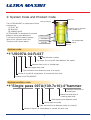
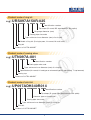
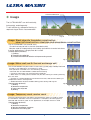
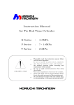
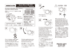
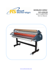
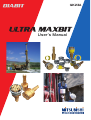
GK23A
User's Manual
Table of Contents
◆ Selection of ULTRA MAXBIT・・・・・・・・・・・・・・2
◆ System and Product Code ・・・・・・・・・・・・・3−4
◆ Usage・・・・・・・・・・・・・・・・・・・・・・・・・・・・・・・・・・・5
◆ Welding Casing Shoe ・・・・・・・・・・・・・・・・・・6−7
◆ Attaching Ring Bit ・・・・・・・・・・・・・・・・・・・・・・・8
◆ Setting Use Condition・・・・・・・・・・・・・・・・・・・・9
◆ Procedure to Unlock
and Relock during Drilling・・・・・・・・・・・・・・・・10
◆ Checking Wear at Pilot Bit ・・・・・・・・・・・11−12
◆ Build-up Welding Repair of Pilot Bit・・・・・・・13
Attachment: Order Sheet・・・・・・・・・・・・・・・・14
SAFETY WARNING
● During use, there is a likehood of tool failure,
take appropriate safety measures.
●This product contains or produces chemicals
known to the State of California to cause cancer,
such as cobalt (7440-4-84)
(Proposition 65, California Health and safety
Code Section 25249.5 et seq.)
Refer to the applicable material safety data sheet.
1
◆ Selection of ULTRA MAXBIT
When selecting a type of ULTRA MAXBIT, make sure that the type of the system
(equal to the minimum inner diameter of a ring bit) and casing pipe size
(outer diameter and maximum thickness) are appropriate to your construction plan.
Then select the most appropriate ring bit type among three types.
For dimensions of each type, refer to the catalog of the ULTRA MAXBIT.
If you would like to order a specialized size, please fill out the order
sheet attached to the manual and contact the contact person of
MITSUBISHI Materials.
Maximum thickness
Type
(Minimum inner diameter)
Pipe outer diameter
Fig.-1
Hammer type
(Thread type for a top hammer)
Models of Ring Bit and Usage
Single pass
This is used when the depth of
drill is shallow and casing pipe is
not removed.
[Usage] Piling work
Fig-2
Normal
This is used when the depth of
drill is deep and casing pipe is not
removed.
[Usage] Well drill work, scout
boring
Fig-3
2
Multi use
This design reduces pulling
resistance at recovery so that a
casing pipe and ring bit can be
used repeatedly.
[Usage] Anchor work, foundation
construction
Fig-4
◆ System Code and Product Code
Max. O.D.
Max. thickness
The ULTRA MAXBIT is composed of three
components
(1) PILOT BIT
(2) RING BIT
(3) CASING SHOE
ULTRA MAXBIT is designed for several
different casing pipe diameters
Casing shoe
To find the correct product, please
Ring bit
refer to the "System code" and
"Product code" shown below
Hammer size or hammer
type, thread type
Tip-shaped hard
metal
Pilot bit
Min. I.D.
Fig.-5
System code
e.g.)US097A-04-R-037
Identification number
Tip shape (R: round, BB: semi-ballistic, SA: spike)
Hammer size (inch.) or thread type
Casing pipe size code
Type: minimum inner diameter (mm) of a ring bit
Model of ring bit (S: single pass, N: normal, M: multi use)
Product of ULTRA MAXBIT
System auxiliary code
e.g.)Single
pass 097A(139.7x10)-4"hammer
Hammer size (inch) or
thread type
Maximum thickness of
a casing pipe (mm)
Casing pipe outer diameter (mm)
Casing pipe size code
Type: minimum inner diameter (mm) of a ring bit
Model of ring bit (S: single pass, N: normal, M: multi use)
3
Product code of ring bit
e.g.)URS097A150R-025
Identification number
Tip shape (R: round, BB: semi-ballistic, SA: spike)
Bit gauge diameter (mm)
Casing pipe size code
Type: minimum inner diameter (mm) of a ring bit
Model of ring bit (S: single pass, N: normal, M: multi use)
Ring bit
Product of ULTRA MAXBIT
Product code of casing shoe
e.g.)UTN097A-001
Identification number
Casing pipe size code
Type: minimum inner diameter (mm) of a ring bit
Specification (N: normal, H: hard type or enhanced type for side drilling, T: top hammer)
Casing top
Product of ULTRA MAXBIT
Product code of pilot bit
e.g.)UP097ADH340R014
Identification number
Tip shape (R: round, BB: semi-ballistic, SA: spike)
Hammer type or thread type
Casing pipe size code
Type: minimum inner diameter (mm) of a ring bit
Pilot bit
Product of ULTRA MAXBIT
4
Horizontal direction
◆ Usage
The ULTRA MAXBIT can drill vertically,
horizontally, and diagonally.
To drill efficiently, adequate flushing is
required. Auger Rod is recommended.
Vertical direction
Fig.-6
Diagonal direction
Usage: Steel pipe pile foundation construction,
pipe roof construction, steel pipe end acceptance construction
The ULTRA MAXBIT has several uses.
*The drill rod may be left in the hole (foundation pile)
*May be used for impregnating surrounding ground with chemical solutions
In these applications, a single pass bit is used.
《Construction process》
1) Drilling
2) Retrieve the pilot bit
3) Infuse the chemical solution to improve the ground
Fig-7
1)
2)
3)
1)
2)
3)
4)
1)
2)
3)
4)
Usage: Water well, earth thermal exchange well
The ULTRA MAXBIT may be used to install casing (collar pipe) in badly fractured
ground. In this application, a normal bit is used.
This operation is carried out in the following sequence.
*Drill hole with ULTRA MAXBIT combined with casing
* Continue to drill hole until solid ground is reached
* When hole is in solid ground, retrieve the pilot bit, leaving the casing and ring
bit in the hole
* Change to a smaller diameter conventional DTH bit, and continue drilling to
complete the hole in solid ground.
* Smaller diameter DTH bit enables drilling past casing and ring bit.
《 Construction process》
Fig-8
1) Drilling
2) Retrieve the pilot bit
3) Insert the single bit
4) Drilling
Usage: Temporary work, anchor work
The hole is drilled through the broken ground and the casing is used to install
the foundation materials. After this operation is complete, the casing pipe is
removed and can be re-used. In this application, a multiple use bit is used.
《 Construction process》
1) Drilling
2) Retrieve the pilot bit
3) Set the foundation materials
Fig-9
4) Retrieve the casing pipe
5
◆ Welding Casing Shoe
The casing shoe must be correctly welded to the casing in order to carry out successful casing
drilling. If the casing shoe is not welded accurately to the casing, mis-alignment will result. This
can cause the following problems.
(1) Hole deviation
(2) Damage to the casing
(3) Damage to the shoulder of pilot bit.
*If these problems arise, the recovery of the pilot bit may not be possible
Chamfer the end of the casing at an angle between 30 - 40 degree (FIG10)
In very difficult broken ground, the following additional operation should be carried out.
Cut a radius of 15 - 20 degree at the following intervals.
30°
−45°
15∼20mm
4"Casing or smaller: 2 Radius cuts
8"Casing or smaller: 4 Radius cuts
1−2mm
(R)
Larger than 8": 6 Radius cuts
(Refer FIG11)
Fig.-11
Fig.-10
Caution
Ensure that all surfaces to be welded are perfectly clean and free from any contamination
including moisture.
Fig.-12
The casing and casing shoe consists of different materials, caution must be taken when welding
these items so that weld cracks are not generated.
Metal components of casing Shoe: S45C (SAE No.1045)
C:0.42-0.48 Si:0.15-0.35 Mn:0.60-0.90 P:<0.30 S:<0.35
Cu:<0.30 Ni+Cr:<0.35
6
Select a low-hydrogen solvent for the casing shoe welding. Pre-heat and post-heat the chamfer of
the casing shoe before and after welding respectively.
Recommended weld solvent: JIS D4313/AWS E7016,JIS YGW11/AWS ER70S-G
Pre-heat: Preheat the groove of the casing shoe to 300°
C.
Post-heat: Post-heat it to approx. 600°
C and cool it down gradually
(Heat it from 300 to 500°
C slowly.)
Take sufficient time to weld them temporarily not to cause a weld crack due to sudden heating or
cooling.
Weld them in the diagonal order as shown in Fig.13.
Completely remove the slag during the temporary welding.
①
③
④
Fig.-13
②
Ensure that sufficient weld is applied to both casing and casing shoe, and excess weld is built up.
Finally grind off excess weld from outer diameter of casing.
*If excess weld is not removed, it will interfere with smooth installation of the casing.
Fig.-14
7
◆ Attaching Ring Bit
The ULTRA MAXBIT system adopts a simple and user-friendly method, which is to couple the ring
bit and casing shoe with a thread.
Attachment of the ring bit is completed only by fitting the thread to the casing top pre-welded to
the first casing pipe.
Ring bit
Casing shoe
Pic.-1
≪Down-the-hole hammer specification≫
Most of the down-the-hole hammers rotate
clockwise. The ring bit and the casing shoe
are fit with left-hand threads.
≪Top hammer specification≫
Most of the top hammers rotate
counterclockwise. The ring bit and the
casing shoe are fit with right-hand threads.
Pic.-2
(Caution)
● Do not apply a grease. Sand may be
caught by the grease.
● Check the nominal type on the sticker
attached on the product.
A product with a different nominal type
can not be used.
Pic.-3
8
◆ Setting Use Condition
The ULTRA MAXBIT is used for simultaneous casing drilling in disintegrative poor ground.
Adoption of a double-pipe bit system enables the system to apply to a broad range of geological
conditions such as a sand layer, weak layer, and boulder layer.
The following drill conditions are recommended.
Rotation Speed of Bit
Standard speed is 15∼20m/min. Refer to the following figure for rotation.
Select the range of uniform rotation during drilling.
Bit rotation speed
Rotation of Bit(min-1)
100
80
60
40
20
0
4
8
12
16
20
24
Nominal Size of Bit (in.)
28
32
Condition of Compressor
● Pressure
◆ Set between 0.7 and 1.0MPa (100∼150psi)
◆ Consider the depth of underground water when drilling through the layer.
(In case of 30m(90ft) depth, add 0.3MPa (45psi) to the air pressure.)
φD
◆ Do not set over 1.5MPa (225psi)
φd
● Air Supply
◆ Set the air supply using the following formula.
2
-d2)
V
(D
Q=
1273500
Q:Air supply(m3 /min)
D:Inside diameter of casing(mm)
d:Outside diameter of jacket or hammer(mm)
V:Air speed 1,100 to 1,500(m/min)
Fig.-15
9
◆ Procedure to Unlock and Relock during Drilling
The ULTRA MAXBIT enables the pilot bit and ring bit to be easily unlocked (separated) and
relocked (reconnect) even during drilling. This mechanism facilitates a flushing action and
enhances efficiency of the subsequent drilling. Follow the procedure below to unlock or relock the
pilot bit and ring bit.
Procedure to unlock (See Fig.-16)
④
① After drilling reaches a certain position, flush the hole while
lightly moving the bit up and down with the bit locked.
② After the piston of the hammer starts operating, slowly
rotate the ring bit counterclockwise one or two revolutions.
③ Raise the bit by 1 to 2m.
④ Perform the flushing action while rotating the bit clockwise.
(Caution)
● Raising the whole pipe with the bit locked may cause
trouble in the locking system.
● If the ring bit is rotated counterclockwise rapidly in the
step ②, inertia generated when the rotation stops gets the
ring bit locked again. Likewise, if the clockwise rotation is
stopped at high speed, the inertia may get the ring bit
unlocked.
①
③
②
Fig.-16.Unlock
②
①
Procedure to relock (See Fig.-17)
① Slowly lower the bit with the air supply stopped while
rotating it clockwise.
② Rotate the bit several times after it is lowered to the
bottom. Slowly raise the bit.
③ Confirm that the pilot bit and ring bit are locked. Supply air
and restart drilling
(Caution)
● If the bit is lowered without stopping the air supply, the
piston is operated and a spline of the pilot bit hits the ring
bit, pushing it forward.
Ensure that the air supply is stopped before lowering the
bit. (See Fig.18.)
● Failure to relock can be caused by moving of the ring bit
forward as shown in Fig.-19.
Supply a small volume of air to operate the piston and
lower the pilot bit so that the pilot bit and ring bit can be
relocked.
①
③
Fig.-17.Relock
Fig.-18
10
Fig.-19
◆ Checking Wear at Pilot Bit
The pilot bit has roles such as receiving energy (percussion, rotation, and feed) supplied from the
drilling machine, drilling the ground the face of the bit, and transmitting the energy to the ring bit
and the casing shoe (See Fig.-20). As shown in Pic-4., wear at the face of the bit and at the parts
to transmit the rotation and percussion energy to the ring bit progresses across the adge, and
eventually the pilot bit reaches the end of its usefulness.
Continuously Using the bit which reaches the end of its usefulness may cause a drilling trouble.
Conducting a periodic wear check is recommended.
Draw the casing pipe
C
(Fixed with welding)
B
Part to
transmit
purcussion
energy
D
A
Part to transmit rotation energy
Fig.-20
Pic.-4
《Major wear check points》
A:Button tip and base material
① If the wear width at the tip end is half of the chip diameter or less, regrind the tip end.
② If the base material around the tip is worn and in a pyorrhea-like condition, tip retention
decreases and pop outs will occur.
B:Part to transmit percussion energy to ring bit
① Use the template to check the wear. 15mm of wear width on the part to transmit the
percussion energy indicates it has reached the end of it's lifetime.
② Abnormal wear is mainly caused by tough drilling conditions and improper use of the system.
③Remove the burr on the angle of the part with a grinder.
C:Shoulder (part to transmit percussion energy to casing shoe)
① Use the template to check the wear. 15mm of wear width on the part to transmit the
percussion energy it has reached the end of it's lifetime.
② Abnormal wear can be caused by hole deviation or a bent pipe.
③ Remove the burr on the angle of the part with a grinder if any.
D:Part to transmit rotation energy to ring bit
① Wear to the half of the spline width indicates it has reached the end of it's lifetime.
② Abnormal wear can be caused by improper locking or reaching the end of the ring bit lifetime.
11
Checking wear at part to transmit percussion energy
Use the checking template to check the wear.
15mm of wear width indicates it has reached the
end of it's lifetime.
Stop using the product this if so.
Part to transmit
percussion energy
Protrusion
Wear check
template
《Fitting the template》
Set the corner of the template to the reference
edge of the protrusion as shown in Fig.-21.
Protrusion
Wear check
template
Brand new pilot
Reference edge
Fig.-21
《Criterion for end of lifetime》
The wear width reaching the mark of wear limit
(a concave) indicates end of the production
lifetime as shown in Fig.-25.
10mm or less
Pilot bit reaching the end of life
Fig.-22
10mm
Initial to medium-term wear
Fig.-23
Wear to be noted
Fig.-24
《Model of template》
Use a template with a proper model No. for each
type as shown in Table-1.
Template model No.
Pic.-5
12
15mm
Wear limit(End of lifetime)
Fig.-25
Model No.
T-01
T-02
T-03
T-04
T-05
T-06
T-07
T-08
T-09
T-10
T-11
T-12
T-13
Table-1
Applicable type of pilot bit
050A, 072A, 097A, 105A, 110A
116A
118A, 127A, 127B, 232A
126A, 128A, 170A
132A, 151A
140A
143A, 270A, 273A, 281A
167A, 192A
165A, 216A, 219A, 228A, 270A
215A, 265A, 300A
396A
240A
157A, 200A, 223A, 354A
◆ Build up Welding Repair of Pilot Bit
While the pilot bit adopts a heat-treated special steel to obtain high abrasion resistance, this
special steel is not suitable for build up welding repair of the worn product.
The following describes the build up welding repair procedure. Carefully follow the procedure to
perform the build up welding repair.
Trouble such as a weld crack can be caused.
A product repaired with the build-up welding can not be guaranteed.
《Build-up welding repair procedure. 》
① Pre-heat the base material to 200 to 300℃.
② Underlay a stainless material letting it penetrate shallowly for the first layer.
③ Weld the second layer and later one with a hardening built-up weld solvent.
④ Gradually cool the pilot bit (Never rapidly cool it.)
⑤ Apply a finishing process.
(Surface the repair area along with the abrasion check template.)
Finishing process
Base material
(Note)
To avoid the tip from
being exposed to the
welding spatter, wind a
wet towel around the
face side of bit.
D309,D316 (JIS Z 3221)
Fig.-26
DF2A hardness 300 or higher (JIS Z 3251)
Wear checking template
30°
Fig.-27
30°
These angles and the length here shall
match the template.
13
ULTRA MAXBIT Order Sheet
Thickness
D3
D2
D1 D4
User Name
Usage
"DTH Model No. or
Thread type"
Rotation direction at
drilling
Drilling Direction
Casing pipe
Ring Bit Model
Right Left
Vertical
Horizontal
Diagonal (angled)
Outer diameter (D2) Wall thickness
Single pass
Normal
Multi use
Ring Bit O.D.
(D1) Manufacturer's recommendation
Ring Bit I.D.
(D4) Manufacturer's recommendation
Maximum O.D. of Pilot Bit (D3) Manufacturer's recommendation
Quantity demanded
Minimum order quantity
Drilling meter / Number of hole
Pilot Bit: Ring Bit & Casing Shoe:
Expected Delivery Time
Remark
Information such as geological conditions, conventionally used bit (a manufacturer), size of
passing through bit gauge and hammer type;
Name of preparer
〈Contact〉
ADVANCED MATERIALS & TOOLS COMPANY
ROCK TOOLS
OVERSEAS OPERATIONS CENTER
TEL(0584)27-5011 FAX(0584)27-5022
http://mrt.mitsubishicarbide.com/
14
Phone number
MMC HARTMETALL GmbH
MITSUBISHI MATERIALS
USA CORPORATION Los Angeles
(Germany)
MMC GIFU PLANT
OVERSEAS OPERATIONS CENTER
(U.S.A.)
(Japan)
RYOKO SANGYO
CORPORATION
(Australia)
MMC METAL SINGAPORE PTE LTD
(Singapore)
MMC METAL DE MEXICO,
S.A.DE C.V.
(Mexico)
MMC METAL DO BRASIL Ltda.
(Brazil)
Japan/ ROCK TOOLS,
OVERSEAS OPERATIONS CENTER:
Godo-cho, Anpachi-Gun, Gifu-Pref. 503-2394, Japan
Tel. 81-584-27-5011 Fax. 81-584-27-5022
E-Mail. [email protected]
Subsidiaries of MITSUBISHI MATERIALS CORPORATION
U.S.A./ MITSUBISHI MATERIALS U.S.A. CORPORATION,
Los Angeles Head Office:
17401, Eastman Street, Irvine, CA. 92614, U.S.A.
Tel. 1-949-862-5176 (1-800-423-1358) Fax. 1-949-862-5184
E-Mail. [email protected]
Germany / MMC HARTMETALL GMBH:
Comeniusstr. 2,40670 Meerbusch, Germany
Tel. 49-2159-9189-41 Fax. 49-2159-9189-79
E-Mail. [email protected]
Singapore/ MMC METAL SINGAPORE PTE LTD:
10, Arumugan Road, #04-00, Lion Industrial Bldg., Singapore 409957
Tel. 65-743-9370 Fax. 65-749-1469
E-Mail. [email protected]
Brazil/ MMC-METAL DO BRASIL LTDA.:
Rua Cincinato Braga, 340 13o- andar.Bela Vista~
CEP 01333-010 Sao
Paulo-SP., BRASIL
Tel. 55-11-3262-5095 Fax. 55-11-3285-4906
E-Mail. [email protected]
Mexico/ MMC-METAL DE MEXICO S.A. DE C.V.
Av. La Canada No.16 Parque Industrial Bernardo Quintana
El Marques, Queretaro.
Tel. 52-442-221-6136 52-442-221-6137
Fax. 52-442-221-6134
E-Mail. [email protected]
Australia/ RYOKO SANGYO CORPORATION
59 Tacoma Circuit Canning Vale, WA 6155 Australia
PO Box 1550, Canning Vale B/C
WA 6970 Australia
Tel. 61-8-9256-4002 Fax. 61-8-9256-4471
E-Mail. [email protected]
HOMEPAGE ADDRESS
●The
http://mrt.mitsubishicarbide.com/
specifications in the catalogue are subject to alternation without notice for improvement of products.
0812
Printed in Japan