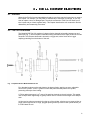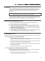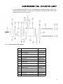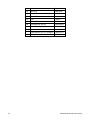
1
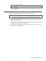
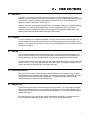
0RGHO . )ODW &HOO
8VHUrV 0DQXDO
% 3ULQWHG LQ 86$
:$55$17<
PerkinElmer Instruments warrants each instrument of its own manufacture to be free of defects in material and
workmanship. Obligations under this Warranty shall be limited to replacing, repairing or giving credit for the purchase price,
at our option, of any instrument returned, shipment prepaid, to our Service Department for that purpose within ONE year of
delivery to the original purchaser, provided prior authorization for such return has been given by an authorized representative
of PerkinElmer Instruments.
This Warranty shall not apply to any instrument, which our inspection shall disclose to our satisfaction, to have become
defective or unworkable due to abuse, mishandling, misuse, accident, alteration, negligence, improper installation, or other
causes beyond our control. This Warranty shall not apply to any instrument or component not manufactured by PerkinElmer
Instruments. When products manufactured by others are included in PerkinElmer Instrumentsequipment, the original
manufacturer's warranty is extended to PerkinElmer Instruments customers.
PerkinElmer Instruments reserves the right to make changes in design at any time without incurring any obligation to install
same on units previously purchased.
THERE ARE NO WARRANTIES THAT EXTEND BEYOND THE DESCRIPTION ON THE FACE HEREOF. THIS
WARRANTY IS IN LIEU OF, AND EXCLUDES ANY AND ALL OTHER WARRANTIES OR REPRESENTATIONS,
EXPRESSED, IMPLIED OR STATUTORY, INCLUDING MERCHANTABILITY AND FITNESS, AS WELL AS ANY AND ALL
OTHER OBLIGATIONS OR LIABILITIES OF PERKINELMER INSTRUMENTS INCLUDING, BUT NOT LIMITED TO,
SPECIAL OR CONSEQUENTIAL DAMAGES. NO PERSON, FIRM OR CORPORATION IS AUTHORIZED TO ASSUME
FOR PERKINELMER INSTRUMENTS ANY ADDITIONAL OBLIGATION OR LIABILITY NOT EXPRESSLY PROVIDED FOR
HEREIN EXCEPT IN WRITING DULY EXECUTED BY AN OFFICER OF PERKINELMER INSTRUMENTS.
6+28/' <285 (48,30(17 5(48,5( 6(59,&(
A. Contact the Customer Service Department (865-482-4411) or your local representative to discuss the problem. In many
cases it will be possible to expedite servicing by localizing the problem to a particular plug-in circuit board.
B. If it is necessary to send any equipment back for service, we need the following information.
1. Model number and serial number.
5. Your telephone number and extension.
2. Your name (instrument user).
6. Symptoms (in detail, including control settings).
3. Your address.
7. Your purchase order number for repair charges (does not apply
to repairs in warranty).
4. Address to which the instrument
should be returned.
8. Shipping instructions (if you wish to authorize shipment by any
method other than normal surface transportation).
C. U.S. CUSTOMERS — Ship the equipment being returned to:
PerkinElmer Instruments
801 S. Illinois Avenue
Oak Ridge, TN 37831
ATTN: Customer Service
PHONE: 865-482-4411
FAX: 865-483-0396
D. CUSTOMERS OUTSIDE OF U.S.A. — To avoid delay in customs clearance of equipment being returned, please contact
the factory or the nearest factory distributor for complete shipping information.
All trademarks used herein are the property of their respective owners.
ii
7$%/( 2) &217(176
1. INTRODUCTION . . . . . . . . . . . . . . . . . . . . . . . . . . . . . . . . . . . . . . . . . . . . . . . . . . . . . . . . . . . . . . . . . . . . .
1.1. Overview . . . . . . . . . . . . . . . . . . . . . . . . . . . . . . . . . . . . . . . . . . . . . . . . . . . . . . . . . . . . . . . . . . . . . . .
1.2. Benefits . . . . . . . . . . . . . . . . . . . . . . . . . . . . . . . . . . . . . . . . . . . . . . . . . . . . . . . . . . . . . . . . . . . . . . . .
1.3. Flat Cell Theory . . . . . . . . . . . . . . . . . . . . . . . . . . . . . . . . . . . . . . . . . . . . . . . . . . . . . . . . . . . . . . . . . .
1.4. Construction . . . . . . . . . . . . . . . . . . . . . . . . . . . . . . . . . . . . . . . . . . . . . . . . . . . . . . . . . . . . . . . . . . . . .
1.5. Galvanic Corrosion . . . . . . . . . . . . . . . . . . . . . . . . . . . . . . . . . . . . . . . . . . . . . . . . . . . . . . . . . . . . . . . .
1
1
1
1
1
1
2. EXPERIMENTAL SETUP . . . . . . . . . . . . . . . . . . . . . . . . . . . . . . . . . . . . . . . . . . . . . . . . . . . . . . . . . . . . . . .
2.1. Overview . . . . . . . . . . . . . . . . . . . . . . . . . . . . . . . . . . . . . . . . . . . . . . . . . . . . . . . . . . . . . . . . . . . . . . .
2.2. Mounting the Sample . . . . . . . . . . . . . . . . . . . . . . . . . . . . . . . . . . . . . . . . . . . . . . . . . . . . . . . . . . . . . .
2.2.1. Sample Mounting Considerations . . . . . . . . . . . . . . . . . . . . . . . . . . . . . . . . . . . . . . . . . . . . . . .
2.2.1.1. General . . . . . . . . . . . . . . . . . . . . . . . . . . . . . . . . . . . . . . . . . . . . . . . . . . . . . . . . . . . .
2.2.1.2. Coatings . . . . . . . . . . . . . . . . . . . . . . . . . . . . . . . . . . . . . . . . . . . . . . . . . . . . . . . . . . .
2.2.1.3. Conductivity . . . . . . . . . . . . . . . . . . . . . . . . . . . . . . . . . . . . . . . . . . . . . . . . . . . . . . . .
2.3. Sample Mounting Procedure . . . . . . . . . . . . . . . . . . . . . . . . . . . . . . . . . . . . . . . . . . . . . . . . . . . . . . . .
2.4. Filling the Reference Electrode Sleeve . . . . . . . . . . . . . . . . . . . . . . . . . . . . . . . . . . . . . . . . . . . . . . . . .
2.4.1. Filling Considerations . . . . . . . . . . . . . . . . . . . . . . . . . . . . . . . . . . . . . . . . . . . . . . . . . . . . . . . .
2.4.2. Filling Procedure . . . . . . . . . . . . . . . . . . . . . . . . . . . . . . . . . . . . . . . . . . . . . . . . . . . . . . . . . . . .
2.5. Filling the Reference Electrode Well . . . . . . . . . . . . . . . . . . . . . . . . . . . . . . . . . . . . . . . . . . . . . . . . . .
2.5.1. Filling Considerations . . . . . . . . . . . . . . . . . . . . . . . . . . . . . . . . . . . . . . . . . . . . . . . . . . . . . . . .
2.5.1.1. Capillary Positioning . . . . . . . . . . . . . . . . . . . . . . . . . . . . . . . . . . . . . . . . . . . . . . . . . .
2.5.2. Filling Procedure . . . . . . . . . . . . . . . . . . . . . . . . . . . . . . . . . . . . . . . . . . . . . . . . . . . . . . . . . . . .
2.6. Filling the Cell . . . . . . . . . . . . . . . . . . . . . . . . . . . . . . . . . . . . . . . . . . . . . . . . . . . . . . . . . . . . . . . . . . .
2.6.1. Filling Considerations . . . . . . . . . . . . . . . . . . . . . . . . . . . . . . . . . . . . . . . . . . . . . . . . . . . . . . . .
2.6.2. Filling Procedure . . . . . . . . . . . . . . . . . . . . . . . . . . . . . . . . . . . . . . . . . . . . . . . . . . . . . . . . . . . .
2.7. Making the Electrical Connections . . . . . . . . . . . . . . . . . . . . . . . . . . . . . . . . . . . . . . . . . . . . . . . . . . . .
3
3
3
3
3
3
3
3
4
4
4
4
4
5
5
5
5
5
6
3. OPERATION . . . . . . . . . . . . . . . . . . . . . . . . . . . . . . . . . . . . . . . . . . . . . . . . . . . . . . . . . . . . . . . . . . . . . . . .
3.1. Overview . . . . . . . . . . . . . . . . . . . . . . . . . . . . . . . . . . . . . . . . . . . . . . . . . . . . . . . . . . . . . . . . . . . . . . .
3.2. Purging . . . . . . . . . . . . . . . . . . . . . . . . . . . . . . . . . . . . . . . . . . . . . . . . . . . . . . . . . . . . . . . . . . . . . . . .
3.3. Stirring . . . . . . . . . . . . . . . . . . . . . . . . . . . . . . . . . . . . . . . . . . . . . . . . . . . . . . . . . . . . . . . . . . . . . . . . .
3.4. Coated Specimens . . . . . . . . . . . . . . . . . . . . . . . . . . . . . . . . . . . . . . . . . . . . . . . . . . . . . . . . . . . . . . . .
3.5. Sample Life . . . . . . . . . . . . . . . . . . . . . . . . . . . . . . . . . . . . . . . . . . . . . . . . . . . . . . . . . . . . . . . . . . . . .
3.6. Capillary Modification . . . . . . . . . . . . . . . . . . . . . . . . . . . . . . . . . . . . . . . . . . . . . . . . . . . . . . . . . . . . . .
3.7. Other Techniques . . . . . . . . . . . . . . . . . . . . . . . . . . . . . . . . . . . . . . . . . . . . . . . . . . . . . . . . . . . . . . . . .
3.8. Cleaning . . . . . . . . . . . . . . . . . . . . . . . . . . . . . . . . . . . . . . . . . . . . . . . . . . . . . . . . . . . . . . . . . . . . . . . .
7
7
7
7
7
7
8
8
8
4. CELL CONSTRUCTION . . . . . . . . . . . . . . . . . . . . . . . . . . . . . . . . . . . . . . . . . . . . . . . . . . . . . . . . . . . . . . . . 9
4.1. Overview . . . . . . . . . . . . . . . . . . . . . . . . . . . . . . . . . . . . . . . . . . . . . . . . . . . . . . . . . . . . . . . . . . . . . . . 9
4.2. Flat Cell Construction . . . . . . . . . . . . . . . . . . . . . . . . . . . . . . . . . . . . . . . . . . . . . . . . . . . . . . . . . . . . . . 9
4.3. Disassembling the Flat Cell . . . . . . . . . . . . . . . . . . . . . . . . . . . . . . . . . . . . . . . . . . . . . . . . . . . . . . . . 10
4.4. Reassembling the Flat Cell . . . . . . . . . . . . . . . . . . . . . . . . . . . . . . . . . . . . . . . . . . . . . . . . . . . . . . . . . 10
5. GALVANIC CORROSION . . . . . . . . . . . . . . . . . . . . . . . . . . . . . . . . . . . . . . . . . . . . . . . . . . . . . . . . . . . . .
5.1. Overview . . . . . . . . . . . . . . . . . . . . . . . . . . . . . . . . . . . . . . . . . . . . . . . . . . . . . . . . . . . . . . . . . . . . . .
5.2. Requirements for Modifying the Flat Cell . . . . . . . . . . . . . . . . . . . . . . . . . . . . . . . . . . . . . . . . . . . . . .
5.3. Modifying the Flat Cell . . . . . . . . . . . . . . . . . . . . . . . . . . . . . . . . . . . . . . . . . . . . . . . . . . . . . . . . . . . .
5.3.1. Removing the Counter Electrode End Plate . . . . . . . . . . . . . . . . . . . . . . . . . . . . . . . . . . . . . . .
5.3.2. Preparing the Second Working Electrode End Plate . . . . . . . . . . . . . . . . . . . . . . . . . . . . . . . .
5.3.3. Installing a Second Working Electrode End Plate . . . . . . . . . . . . . . . . . . . . . . . . . . . . . . . . . .
13
13
13
13
13
13
14
APPENDIX A. SPECIFICATIONS . . . . . . . . . . . . . . . . . . . . . . . . . . . . . . . . . . . . . . . . . . . . . . . . . . . . . . . . . 15
A.1. Dimensions . . . . . . . . . . . . . . . . . . . . . . . . . . . . . . . . . . . . . . . . . . . . . . . . . . . . . . . . . . . . . . . . . . . . 15
A.2. Characteristics . . . . . . . . . . . . . . . . . . . . . . . . . . . . . . . . . . . . . . . . . . . . . . . . . . . . . . . . . . . . . . . . . . 15
iii
A.3. Materials . . . . . . . . . . . . . . . . . . . . . . . . . . . . . . . . . . . . . . . . . . . . . . . . . . . . . . . . . . . . . . . . . . . . . . 15
APPENDIX B. PARTS LIST . . . . . . . . . . . . . . . . . . . . . . . . . . . . . . . . . . . . . . . . . . . . . . . . . . . . . . . . . . . . . . 17
INDEX . . . . . . . . . . . . . . . . . . . . . . . . . . . . . . . . . . . . . . . . . . . . . . . . . . . . . . . . . . . . . . . . . . . . . . . . . . . . . . . 19
iv
Model K0235 Flat Cell User’s Manual
,1752'8&7,21
1.1. Overview
The Princeton Applied Research Model K0235 Flat Cell gives you a simple, easy-to-use cell for
electrochemical testing of any flat specimen larger than 0.75 in.2 (1.9 cm2). The practical design
of the Flat Cell allows it to accommodate a wide range of electrode shapes and sizes, eliminating
the need for machining or special mechanical preparation.
1.2. Benefits
Corrosion measurement and impedance analysis can sometimes involve elaborate sample
preparation and setup procedures. To make these tasks simpler, the Model K0235 Flat Cell
provides these benefits:
Accommodates a wide variety of flat specimens with no mechanical preparation.
Enables quick changing of test electrodes.
Disassembles and reassembles quickly and easily.
Operates with a small sample volume (less than 300 ml).
Models the metal actually used in service more closely than other cells.
Eliminates metal deformation and induced stresses resulting from cutting, shearing, or
punching of sample.
Simplifies galvanic corrosion experiments by allowing easy replacement of counter electrode
with a second test electrode.
1.3. Flat Cell Theory
The cylindrical shape of the Flat Cell and the placement of the counter electrode directly
opposite the working electrode provide optimum current distribution on the surface of the working
electrode. Offsetting the reference electrode and using a 1.5 mm OD capillary as a Luggin probe
result in minimum shielding of the working electrode surface. Consequently, you can perform
more accurate impedance measurements and reduce the potential error due to uncompensated
resistance between the Luggin capillary and the working electrode.
1.4. Construction
The Flat Cell is constructed of a Pyrex™ glass cylinder body with polypropylene end caps. The
Flat Cell's sample holder can accommodate test electrodes ranging from 3/4-in. (19-mm)
diameter discs to 6 × 6-in. (152 × 152-mm) flat panels. In fact, virtually any size specimen can
be used, provided it is flat and less than 3/8 in. (9.5 mm) thick.
1.5. Galvanic Corrosion
The Flat Cell simplifies galvanic corrosion experiments. If you replace the platinum counter
electrode end cap with an end cap containing a second test electrode, you can perform galvanic
corrosion experiments in the same cell you use for conventional corrosion experiments.
1
2
Model K0235 Flat Cell User’s Manual
(;3(5,0(17$/ 6(783
2.1. Overview
The K0235 Flat Cell comes completely assembled and ready to use. To prepare it for an
experiment, you mount the sample, fill the cell and reference electrode well with test solution, fill
the reference electrode with silver/silver chloride solution, and make the electrical connections.
This chapter describes the procedures for each of these operations.
2.2. Mounting the Sample
2.2.1. Sample Mounting Considerations
2.2.1.1. General
The Flat Cell clamp can accommodate many different types and shapes of sample
materials. The wide-notch clamping frame will hold a large block, a long bar, or irregular
shapes. This allows you to spot test a large sample without having to fit it into a conventional
cell.
There are three physical requirements for a sample:
The sample must be no thicker than 3/8 in. (9.5 mm).
NOTE If your sample is less than 3-3/8 in. (86 × 86 mm) in length or width, you can insert
the narrow end vertically into the opening at the top of the clamping frame. In this
case, the sample can be up to 3/4 in. (19 mm) thick.
The surface exposed to the solution must be flat or slightly convex.
The sample must be able to withstand the pressure applied by the shoe and clamping screw.
2.2.1.2. Coatings
Note that only a small area of the sample surface is exposed to the test solution. Thus, for
coated samples, you don't need to immerse the entire sample in the coating or coat the unused
surface of the sample.
2.2.1.3. Conductivity
Since the end plates are non-conductive and the clamping frame never comes into contact with
the test solution, the sample can touch the end plate and clamping frame without causing a
conductivity problem. However, you should make sure that the metal clamping frame does not
come into contact with a metal bench surface. This would ground the working electrode and
likely damage the potentiostat.
2.3. Sample Mounting Procedure
You mount the sample by applying pressure with an adjustable shoe assembly. The shoe makes
electrical contact with the back surface of the sample and secures the sample against a Teflon
gasket. The gasket allows an area of 1 cm2 to be exposed to the cell solution. Follow this
procedure to mount the sample:
1. With the cell resting on a flat surface, back off the screw until there is enough space to insert
your sample between the shoe and the end plate.
3
2. Position the sample over the hole in the end plate so that it is flush against the knife-edge
Teflon gasket.
NOTE If you're using a small sample, hold it against the hole with one hand while you screw
the shoe in with the other. If you're using a large sample, let the sample rest in the
clamping frame notch while screwing in the shoe.
3. Tighten the screw until the shoe firmly secures the sample against the Teflon gasket.
Moderate pressure is enough to allow the Teflon gasket to conform to the sample surface
and create a leak-free seal. Overtightening can break the end plate or create a poor seal.
2.4. Filling the Reference Electrode Sleeve
2.4.1. Filling Considerations
One of the most common problems in electrochemical measurements is the presence of trapped
air in the Luggin capillary or reference electrode, resulting in continuity problems and unreliable
experimental data. In the following instructions, be sure to carefully perform the steps relating to
trapped air.
2.4.2. Filling Procedure
Use this procedure to fill the reference electrode sleeve:
1. Remove the silver reference electrode wire from the glass reference electrode sleeve.
2. Fill a 9-in. Pasteur pipette with a silver chloride/saturated potassium chloride reference
electrode solution (Princeton Applied Research Price List Number RDE0022).
3. Insert the pipette all the way to the bottom of the sleeve.
4. Begin squeezing the ball of the pipette while slowly drawing it out of the sleeve. Fill to just
below the air hole near the open end of the sleeve (about 1/2 in. [13 mm] from the end).
NOTE Make sure you begin squeezing when the pipette is at the very bottom of the sleeve
and draw the pipette out evenly. If you don't follow this procedure carefully, air
bubbles can form.
5. Inspect the solution for trapped air. If you see any, shake out any air bubbles by holding the
sleeve at the open end and giving it one or two good shakes. The motion is similar to the
motion you use to reset a thermometer.
6. Reinsert the reference electrode wire into the sleeve. Make sure the cap is secured over the
sleeve.
2.5. Filling the Reference Electrode Well
2.5.1. Filling Considerations
It's important to fill the reference electrode well before filling the cell. If you don't, you may not
build enough of a pressure differential between the well and the cell to force the solution in the
well through the Luggin capillary. This can result in trapped air in the capillary and unreliable
experimental data.
4
Model K0235 Flat Cell User’s Manual
2.5.1.1. Capillary Positioning
The Luggin capillary is positioned at the factory to point directly at the center of the working
electrode (the exposed 1-cm2 part of the sample). If the capillary has shifted from shipping
vibration or other reasons, you must position it correctly. See Section 4.3 for information about
how to disassemble the cell and position the capillary. You can also reposition the capillary
slightly by moving the end in the reference electrode well with a glass stirring rod.
2.5.2. Filling Procedure
Use this procedure to fill the reference electrode well:
1. Grasp the reference electrode by the plug and remove it from the well.
2. Insert a funnel into the reference electrode well.
3. Pour enough solution into the well to fill it about 3/4 full (about 5 ml of solution should do it).
Use the same solution that you use to fill the cell.
4. Observe the solution in the Luggin capillary. Unless the capillary is constricted or has
trapped air bubbles, the solution in the well should flow through the capillary by capillary
action. The flow of solution from the well to the cell should create a continuous line of
solution in the capillary, unbroken by air bubbles, and drops of solution should begin to fall
into the cell. Make sure that this is the case.
5. If solution is flowing, perform the procedure to fill the cell before the solution in the well falls
below the capillary and air is re-introduced into the system (see below).
6. If you suspect air bubbles, use this technique to eliminate them:
Grasping the plug, carefully but firmly insert the reference electrode into the well. This
plunger action will usually force solution through the capillary and remove the trapped air.
If air bubbles remain, pump them out. First remove the reference electrode sleeve from the
well plug. Then insert a piece of glass tubing through the hole in the plug, attach some
Tygon™ tubing to the end of the tube outside the well, and attach a rubber bulb to the Tygon
tubing. Use the bulb to apply just enough pressure to force solution through the well without
spilling solution from the top of the well.
7. When you're sure you've eliminated all the trapped air, make sure the reference electrode is
securely seated in the well and perform the cell filling procedure. This completes the
procedure.
2.6. Filling the Cell
2.6.1. Filling Considerations
It's important to fill the cell after filling the reference electrode well. If you don't, you may not
build enough of a pressure differential between the well and the cell to force the solution in the
well through the Luggin capillary. This can result in trapped air in the capillary and unreliable
experimental data.
2.6.2. Filling Procedure
Use this simple funneling procedure to fill the cell:
1. Remove the drain plug from the top of the cell.
2. Insert a funnel into the hole.
Chapter 2 — EXPERIMENTAL SETUP
5
3. Pour 250 ml of solution into the cell.
NOTE If you prefer, you can also use a syringe with a short length of Tygon tubing attached
to fill the cell.
4. Reinsert the drain plug.
2.7. Making the Electrical Connections
Use the following procedure to connect the Flat Cell to your potentiostat.
NOTE In this procedure, we assume you are using a Princeton Applied Research potentiostat. If
you are not, your electrical leads may be of different colors than those described here.
However, the names of the leads are generally the same throughout the industry.
1. Connect the red counter electrode lead to the counter electrode flange (located at the end
opposite the clamping frame).
2. Connect the green working electrode lead to the working electrode flange (located at the top
of the shoe assembly attached to the clamping frame).
3. Plug the reference electrode lead into the reference electrode jack on the electrometer (the
jack is white on most electrometers).
6
Model K0235 Flat Cell User’s Manual
23(5$7,21
3.1. Overview
In general, you use the Flat Cell as you would any other cell. The unique design is primarily
intended to make it easier to prepare and mount large or irregularly shaped samples and to allow
you to perform galvanic corrosion experiments more conveniently. (For information about
galvanic corrosion experiments, see Chapter 5.)
However, there are a few special cases that make it necessary to change your normal operating
procedures. For example, when deaeration is a critical experimental factor, you need a
convenient method of purging the solution. Stirring also requires special considerations. This
chapter briefly describes the procedures that cover these cases.
3.2. Purging
For some applications, it's recommended that you purge the test solution while filling the cell. To
do this, connect the purge gas to the cell inlet port and allow purge gas to flow during the filling
operation. You can use any flow rate you like, as long as the agitation does not force test solution
through the outlet port.
3.3. Stirring
You can place a magnetic stirrer at the bottom of the cell to keep the solution homogeneous.
Keep in mind that stirring will not prevent the buildup of reaction products on the surface of the
working electrode. It will only stop the buildup of concentration gradients in the test solution.
To insert a stirrer, remove the drain plug, drop the stirrer into the test solution, and let it fall to the
bottom of the cell. Then center the cell on top of the stirrer plate. If the stirrer is positioned too
close to the reference electrode well, move the stirrer plate.
3.4. Coated Specimens
The Flat Cell also makes it easier to prepare coated specimens for evaluation using corrosion
and electrochemical impedance test methods. You can apply a coating to a test panel and use it
as a specimen without further sizing or preparation. This eliminates edge coating and any
coating damage that might occur during machining.
3.5. Sample Life
There are three typical ways of maintaining a fresh test specimen. You can change the sample
before each measurement. Or, if you are using a large sample, you can simply reposition the
sample block so that a fresh area is exposed to the test solution. You can also repolish samples
and use them again.
For coated samples, you may want to replace the sample before each run, unless you're sure
that no damage has been done to the coating. You can also recoat used samples.
7
3.6. Capillary Modification
Some research suggests that a lower resistance in the test solution path in the capillary will
improve performance. This is true in cases where you are using high-resistance test solution or
when you need very fast electrode performance. In these cases, you can reduce the effective
resistance of the test solution path by inserting a small inert conductor (platinum, for example) in
the capillary tube. Do not connect the wire at either end. It simply rests in the capillary to lower
the impedance between the test solution at the tip of the capillary and the test solution in the
reference electrode well.
3.7. Other Techniques
The Flat Cell allows you to perform many of the special techniques you perform on other cells.
For example, you can set up an apparatus to control the temperature of the test solution, mix
solutions, or inject a dye into the solution. Set up these operations as you normally would,
making allowances for the design of the Flat Cell.
3.8. Cleaning
Use mild detergent and warm water to clean the cell.
8
Model K0235 Flat Cell User’s Manual
&(// &216758&7,21
4.1. Overview
Although the Flat Cell comes assembled and ready-to-use, there may be times when you want to
take it apart. For example, you may want to wash and dry it thoroughly for storage, or you may
want to replace a worn or damaged part. The simple construction of the Flat Cell allows you to
take it apart and put it back together easily. This chapter describes the cell construction and the
disassembly and reassembly procedures.
4.2. Flat Cell Construction
The Model K0235 Flat Cell consists of a glass cylinder clamped horizontally between two end
plates (see Fig. 1). One end plate houses the working electrode and the other houses the counter
electrode. The reference electrode is housed in a Luggin well, with a fixed Teflon Luggin
capillary protruding from the bottom of the well.
Fig. 1. Exploded View of Model K0235 Flat Cell.
Four threaded rods secure the end plates to the glass cylinder, applying an even, adjustable
force on the cylinder. A Viton™ gasket on each end plate seals the plate to the cylinder,
preventing electrolyte from leaking.
A Teflon gasket exposes a 1-cm2 area of the working electrode to the cell solution. This gasket
uses a unique knife-edge design to greatly reduce crevice corrosion at the edges of the sample
area.
An inlet and an outlet port protrude from the top of the cylinder, allowing you to pump solution or
purge gas through the cell. A large, plugged opening at the top center of the cylinder allows you
to fill and drain the cell.
9
4.3. Disassembling the Flat Cell
Use the following procedure to completely disassemble the Flat Cell.
NOTE As noted in the procedure, the steps that ask you to remove the end plate gaskets and
the counter electrode are optional. There is no need to remove them unless they are
defective.
1. Remove the reference electrode from the Luggin well. Be careful not to damage the frit or
spill any corrosive solution. Immerse the frit in water if you don't plan to return it to the well
within a few hours.
2. Drain the well. If the solution in the well is not corrosive, simply empty it into a sink by
turning the cell over. If the solution is corrosive, insert a hose into the well, apply a vacuum,
and remove the solution. Make sure to dispose of the solution safely.
3. Drain the cell. Again, if the solution in the cell is not corrosive, remove the plug and empty it
into a sink by turning the cell over.
However, if the solution is corrosive, push one of the hoses to the bottom of the cell and
apply a vacuum. Or, push both hoses to the bottom and pump the solution out.
4. Place the cell horizontally on a flat surface.
5. Being careful not to let the glass cylinder slip and break, remove the four threaded rods by
unscrewing the knobs until they slip out freely from the working electrode end plate. Slide the
rods completely out of the counter electrode end plate. Remove the washer from each rod.
6. Rinse the glass cylinder and well thoroughly.
NOTE If you don't need to remove the gaskets or the counter electrode, you're finished. If
you have reason to remove one or both, proceed to step 7. Steps 7 and 8 are both
optional.
7. If necessary, remove the gaskets from the working and counter electrode end plates. A
gasket will usually fall out if you hold the plate upside down. If it doesn't, gently insert an
instrument with a thin point (such as a straight pin) along the edge of the gasket and lift it
out.
8. If necessary, remove the counter electrode from the end plate. First pull the Teflon cap off of
the handle. Then insert a thin blade under the platinum/rhodium screen and lift it up without
bending the screen. When the screen clears the lip of the recess, carefully slide it out.
4.4. Reassembling the Flat Cell
Use the following procedure to reassemble the Flat Cell.
NOTE As noted in the procedure, if you did not remove the end plate gaskets and the counter
electrode during disassembly, you do not have to perform the steps that ask you to
reinstall them.
1. If you did not remove the counter electrode during disassembly, skip this step. If you did
remove it, locate the slot in the recess of the counter electrode end plate. Then carefully
slide the electrode handle into the slot until the screen clears the lip of the recess. Insert the
Teflon cap back onto the handle.
10
Model K0235 Flat Cell User’s Manual
2. If you did not remove the gaskets during disassembly, skip this step. If you did remove them,
lightly coat each replacement gasket with solvent-soluble grease. Then insert a gasket into
the groove on each end plate. The gaskets should lay in easily without force-fitting or the use
of special tools.
3. Insert a Teflon washer onto each rod.
4. Hold the counter electrode end plate in front of you with the recess down, and insert the four
rods through the holes from the top.
5. Without letting the rods slip out, turn the end plate over and allow the four knobs to rest on a
flat surface. The recess should be pointing up.
6. Insert the glass cylinder into the groove on the counter electrode end plate. The rim of the
cylinder should rest on the gasket. The ports and the well should protrude in roughly the
same direction as the counter electrode handle and Teflon cap.
7.
NOTE You may want a second person to help in the next three steps.
Holding the glass cylinder securely against the counter electrode end plate gasket, rotate the
assembly to a horizontal position. The end plate should be resting on the two rubber feet, the
rods should be horizontal, and the ports and well should point straight up.
8. Keeping the cylinder secure against the counter electrode end plate, insert the working
electrode end plate onto the four rods. Screw the rods in until the rim of the cylinder just
touches the gasket in the working electrode end plate.
9. Making sure the resting surface is flat, gradually tighten the four rods until the seal between
the gasket and cylinder is firm. Make sure the assembly rests squarely on the surface as you
tighten the knobs. There should be no wobble.
10. Remove the drain plug and fill the cell. Pouring the solution into the cell through a funnel is
the easiest way and works well.
11. Fill the well to within 20 mm of the top with the same solution, again using a funnel.
12. Insert the reference electrode into the well. Be careful not to damage the frit or spill any
corrosive solution.
Chapter 4 — CELL CONSTRUCTION
11
12
Model K0235 Flat Cell User’s Manual
*$/9$1,& &25526,21
5.1. Overview
The Flat Cell simplifies galvanic corrosion experiments. If you replace the platinum counter
electrode end plate with an end plate containing a second working electrode, you can perform
galvanic corrosion experiments with the same cell you use for conventional corrosion
experiments.
NOTE There is one limitation in the galvanic corrosion configuration. The knobs protruding from
the second end plate limit the size and shape of the second sample.
This chapter lists the requirements for this modification and describes the procedures. See the
Princeton Applied Research Model 342 SoftCorr™ Corrosion Measurement Software Operator's
Manual for further information on the galvanic corrosion hookup and operation.
5.2. Requirements for Modifying the Flat Cell
To modify the Flat Cell for galvanic corrosion experiments, you will need these items:
The complete Flat Cell in its standard configuration.
An additional working electrode end plate assembly, including the end plate, clamping
assembly, and shoe assembly. It is listed in the Princeton Applied Research catalog as
Sample End Cap, Part Number K0259.
A cable to connect the reference electrode to the Model 273 AUX A/D connector (Princeton
Applied Research Cable Number 6020-0206).
A cord and alligator clip to short the reference and counter electrodes on the electrometer
(Princeton Applied Research Part Numbers 6006-0012-0 and 2100-0110-0).
5.3. Modifying the Flat Cell
To modify the cell for galvanic corrosion experiments, perform the following procedures in the order presented:
5.3.1. Removing the Counter Electrode End Plate
1. Rest two books flat on your working surface about 3/4 in. (19 mm) apart. Both books should
be about the same thickness, and at least 1 in. (25 mm) thick.
2. With all wires disconnected and all solution emptied, place the cell vertically on the books,
with the clamp screw positioned in the gap between the books.
3. Remove the four threaded rods by unscrewing the knobs until they slip out freely from the
working electrode end plate.
4. Slide the rods completely out of the counter electrode end plate.
5.3.2. Preparing the Second Working Electrode End Plate
Before modifying the Flat Cell for galvanic corrosion experiments, you must first prepare the
second working electrode end plate. Follow this procedure:
1. Remove the four screws from the side of the clamping frame on the second working
electrode end plate and remove the end plate.
13
NOTE Throughout this procedure, we'll refer to the two sides of the end plate as the inner
and outer surfaces. The inner surface is the surface with the large circular groove
containing the black O-ring. It contacts the glass cylinder. The outer surface is the
surface with the the small hole containing the white Teflon O-ring. It contacts the
sample.
2. Take one of the four threaded rods removed in the last procedure and screw it into one of
the threaded fittings on the outer surface of the end plate. Continue screwing it in until about
1/2 in. (13 mm) of the rod protrudes from the inner surface.
3. Repeat step 2 for the other three threaded rods. About 1/2 in. of each threaded rod should be
protruding from the inner surface of the end plate.
4. Turn the end plate up and let it rest on the four short legs — the 1/2-in. sections of the
threaded rods.
5. Press down on the end plate until all four of the fittings pop out of their holes.
6. Remove the threaded rods from the fittings.
5.3.3. Installing a Second Working Electrode End Plate
1. Make sure the O-ring is flat and properly seated.
2. Take the second working electrode end plate and fit the O-ring groove onto the top of the
glass cylinder. Make sure the end of the cylinder contacts the O-ring squarely.
3. Remove the plastic washers from each of the threaded rods and fit them into the recesses
on the outer surface of the end plate. Insert the rounded edge of the washer into the recess.
4. Insert the threaded rods through the four holes in the second end plate and screw them a few
turns into the first end plate.
5. Without applying too much pressure on a single corner, turn each rod a few turns at a time
until the second end plate fits snugly on the glass cylinder. Do not tighten too much, or you
will overstress the O-rings and glass cylinder. Stop tightening when the rod stops turning
smoothly with a firm twist of the knob.
6. Replace the clamping frame on the second end plate.
NOTE This completes the procedure. Notice, however, that the knobs protruding from the
second end plate limit the size and shape of the second sample.
14
Model K0235 Flat Cell User’s Manual
$33(1',; $ 63(&,),&$7,216
A.1. Dimensions
Cell Volume 250 ml
Working-to-Counter Electrode Distance 80 mm
Working Electrode Area 1 cm2 (standard)
Luggin Well Dimensions 12 mm diameter × 60 mm deep
Luggin Well Volume 5 ml
A.2. Characteristics
pH Range 2–13
Temperature Limit 80°C
A.3. Materials
Glass cylinder Pyrex
End plates Polypropylene
Sealing gaskets Viton
Luggin capillary Teflon
Reference electrode Silver
Reference electrode solution Silver chloride/saturated potassium chloride
Counter electrode Platinum/rhodium
Sample gasket Teflon
15
16
Model K0235 Flat Cell User’s Manual
$33(1',; % 3$576 /,67
If you need replacement parts, use Fig. 2 to locate the part, note the circled item number, then
find the matching line number on the left side of the parts list. Use the part description and part
number on the line to order your part.
Fig. 2. Flat Cell Assembly Parts Diagram.
Item
Description
Part Number
1
Clamping Screw
2517-1343A
2
Shoe Assembly
2517-1345A
3
Clamping Frame
222594
4
Screw (#10-32), stainless steel
2811-0280-0
5
Nut, Rivnut
2806-0086
6
Gasket, Teflon
MP1239
7
Resting Foot
2800-0042
8
Screw (#4-40), stainless steel
2811-0414-0
9
Working Electrode End Plate
219806
10
Gasket, Viton
OR0142
11
Glass Cylinder (Flat Cell)
219808
12
Tubing, Tygon
3100-0094-0
13
Drain Plug
2805-0043
14
Reference Electrode
219995
17
Item
18
Description
Part Number
15
Well Plug
2805-0044
16
Tubing, Microline #18200
232117
17
Counter Electrode
219810
18
Cap
230213
19
Counter Electrode End Plate
219807
20
Threaded Rod (#10-32)
2502-0026-A
21
Washer, Flat Nylon
2815-0048-0
22
Knob
2406-0311
Filling Solution, 0.5 oz., KCl/AgCl2
1601-0167-0
Tubing, Silicone
232387
Model K0235 Flat Cell User’s Manual
,1'(;
air bubbles . . . . . . . . . . . . . . . . . . . . . . . . . . . . . . . . 4, 5
benefits . . . . . . . . . . . . . . . . . . . . . . . . . . . . . . . . . . . . 1
cable, reference electrode to Model 273 . . . . . . . . . . . . 13
cap . . . . . . . . . . . . . . . . . . . . . . . . . . . . . . . . . . . . . . 18
capillary
modification . . . . . . . . . . . . . . . . . . . . . . . . . . . . . . . 8
positioning . . . . . . . . . . . . . . . . . . . . . . . . . . . . . . . . 5
cell -- see Flat Cell . . . . . . . . . . . . . . . . . . . . . . . . . . . . 1
characteristics, Flat Cell . . . . . . . . . . . . . . . . . . . . . . . . 15
clamping assembly . . . . . . . . . . . . . . . . . . . . . . . . . . . 13
clamping frame . . . . . . . . . . . . . . . . . . . . . 3, 6, 13, 14, 17
clamping screw . . . . . . . . . . . . . . . . . . . . . . . . . . . . 3, 17
cleaning . . . . . . . . . . . . . . . . . . . . . . . . . . . . . . . . . . . . 8
coated specimens . . . . . . . . . . . . . . . . . . . . . . . . . . . . . 7
coatings . . . . . . . . . . . . . . . . . . . . . . . . . . . . . . . . . . . . 3
conductivity . . . . . . . . . . . . . . . . . . . . . . . . . . . . . . . . . 3
construction . . . . . . . . . . . . . . . . . . . . . . . . . . . . . . . . . 1
corrosion
galvanic . . . . . . . . . . . . . . . . . . . . . . . . . . . . . . . 1, 13
corrosive solutions . . . . . . . . . . . . . . . . . . . . . . . . 10, 11
counter electrode . . . . . . . . . . . . . . . . . . . . 1, 9, 10, 15, 18
end plate . . . . . . . . . . . . . . . . . . . . . . . . . . . . 9-11, 18
lead . . . . . . . . . . . . . . . . . . . . . . . . . . . . . . . . . . . . . 6
removing the end plate . . . . . . . . . . . . . . . . . . . . . . 10
shorting reference and counter electrodes . . . . . . . . . 13
current distribution . . . . . . . . . . . . . . . . . . . . . . . . . . . . . 1
cylinder
glass . . . . . . . . . . . . . . . . . . . . . . . . . . . . . 1, 9-11, 14
dimensions, flat cell . . . . . . . . . . . . . . . . . . . . . . . . . . . 15
disassembling the Flat Cell . . . . . . . . . . . . . . . . . . . . . 10
disposing of solution . . . . . . . . . . . . . . . . . . . . . . . . 10
drain plug . . . . . . . . . . . . . . . . . . . . . . . . . . . . 5-7, 11, 17
edge coating . . . . . . . . . . . . . . . . . . . . . . . . . . . . . . . . . 7
electrical connections . . . . . . . . . . . . . . . . . . . . . . . . . . 6
electrometer . . . . . . . . . . . . . . . . . . . . . . . . . . . . . . . . . 6
end cap . . . . . . . . . . . . . . . . . . . . . . . . . . . . . . . . . . . . 1
end plates . . . . . . . . . . . . . . . . . . . . . . . . . . . . . . . . 9, 10
installing a second working electrode end plate . . . . . 14
preparing the second working electrode end plate . . . 13
removing the counter electrode end plate . . . . . . . . . 13
filling the cell . . . . . . . . . . . . . . . . . . . . . . . . . . . . . . . . . 5
filling the reference electrode sleeve . . . . . . . . . . . . . . . . 4
filling the reference electrode well . . . . . . . . . . . . . . . . . . 4
Flat Cell
cleaning . . . . . . . . . . . . . . . . . . . . . . . . . . . . . . . . . . 8
construction . . . . . . . . . . . . . . . . . . . . . . . . . . . . . . . 1
dimensions . . . . . . . . . . . . . . . . . . . . . . . . . . . . . . 15
disassembly . . . . . . . . . . . . . . . . . . . . . . . . . . . . . . 10
disposing of solution . . . . . . . . . . . . . . . . . . . . . . . . 10
filling . . . . . . . . . . . . . . . . . . . . . . . . . . . . . . . . . . . . 5
inlet port . . . . . . . . . . . . . . . . . . . . . . . . . . . . . . . . . . 7
materials . . . . . . . . . . . . . . . . . . . . . . . . . . . . . . . . 15
reassembly . . . . . . . . . . . . . . . . . . . . . . . . . . . . . . 10
theory . . . . . . . . . . . . . . . . . . . . . . . . . . . . . . . . . . . 1
volume . . . . . . . . . . . . . . . . . . . . . . . . . . . . . . . . . 15
flow rate . . . . . . . . . . . . . . . . . . . . . . . . . . . . . . . . . . . . 7
frit, reference electrode . . . . . . . . . . . . . . . . . . . . . 10, 11
galvanic corrosion . . . . . . . . . . . . . . . . . . . . . . . . . . 1, 13
gaskets . . . . . . . . . . . . . . . . . . . . . . . . . . . . . . 3, 10, 15
knife-edge Teflon . . . . . . . . . . . . . . . . . . . . . . 4, 9, 17
Viton . . . . . . . . . . . . . . . . . . . . . . . . . . . . . . . . . 9, 15
glass cylinder -- see cylinder, glass . . . . . . . . . . . . . . . . . 1
grounding the working electrode . . . . . . . . . . . . . . . . . . . 3
induced stresses . . . . . . . . . . . . . . . . . . . . . . . . . . . . . . 1
inlet port . . . . . . . . . . . . . . . . . . . . . . . . . . . . . . . . . . 7, 9
installing a second working electrode end plate . . . . . . . 14
irregular sample shapes . . . . . . . . . . . . . . . . . . . . . . . . . 3
knife-edge Teflon gasket . . . . . . . . . . . . . . . . . . . . . . 4, 9
knob . . . . . . . . . . . . . . . . . . . . . . . . . . . . . . . . . . . . . 18
Luggin capillary . . . . . . . . . . . . . . . . . . . . . . . 1, 4, 5, 9, 15
Luggin probe . . . . . . . . . . . . . . . . . . . . . . . . . . . . . . . . 1
Luggin well . . . . . . . . . . . . . . . . . . . . . . . . . . . . . . . 9, 10
dimensions . . . . . . . . . . . . . . . . . . . . . . . . . . . . . . 15
volume . . . . . . . . . . . . . . . . . . . . . . . . . . . . . . . . . 15
magnetic stirrer . . . . . . . . . . . . . . . . . . . . . . . . . . . . . . . 7
metal deformation . . . . . . . . . . . . . . . . . . . . . . . . . . . . . 1
mounting the sample . . . . . . . . . . . . . . . . . . . . . . . . . . . 3
Nut, rivnut . . . . . . . . . . . . . . . . . . . . . . . . . . . . . . . . . . 17
O-ring . . . . . . . . . . . . . . . . . . . . . . . . . . . . . . . . . . . . 14
other techniques . . . . . . . . . . . . . . . . . . . . . . . . . . . . . . 8
outlet port . . . . . . . . . . . . . . . . . . . . . . . . . . . . . . . . . . . 9
parts list . . . . . . . . . . . . . . . . . . . . . . . . . . . . . . . . . . . 17
Pasteur pipette . . . . . . . . . . . . . . . . . . . . . . . . . . . . . . . 4
pH range . . . . . . . . . . . . . . . . . . . . . . . . . . . . . . . . . . 15
platinum/rhodium screen . . . . . . . . . . . . . . . . . . . . . . . 10
potentiostat
connecting the cell to . . . . . . . . . . . . . . . . . . . . . . . . 6
purging . . . . . . . . . . . . . . . . . . . . . . . . . . . . . . . . . . . . . 7
reassembling the Flat Cell . . . . . . . . . . . . . . . . . . . . . . 10
reference electrode . . . . . . . . . . . . . . . . . . . . . 1, 9, 15, 17
filling . . . . . . . . . . . . . . . . . . . . . . . . . . . . . . . . . . . . 5
frit . . . . . . . . . . . . . . . . . . . . . . . . . . . . . . . . . . . . . 10
lead . . . . . . . . . . . . . . . . . . . . . . . . . . . . . . . . . . . . . 6
shorting reference and counter electrodes . . . . . . . . . 13
sleeve . . . . . . . . . . . . . . . . . . . . . . . . . . . . . . . . . . . 4
solution . . . . . . . . . . . . . . . . . . . . . . . . . . . . . . . 4, 15
well . . . . . . . . . . . . . . . . . . . . . . . . . . . . . . . . . . . . . 4
wire . . . . . . . . . . . . . . . . . . . . . . . . . . . . . . . . . . . . . 4
replacement parts . . . . . . . . . . . . . . . . . . . . . . . . . . . . 17
repolishing samples . . . . . . . . . . . . . . . . . . . . . . . . . . . . 7
resting foot . . . . . . . . . . . . . . . . . . . . . . . . . . . . . . . . . 17
sample
area . . . . . . . . . . . . . . . . . . . . . . . . . . . . . . . . . . . . . 3
end cap . . . . . . . . . . . . . . . . . . . . . . . . . . . . . . . . . 13
gasket . . . . . . . . . . . . . . . . . . . . . . . . . . . . . . . . . . 15
life . . . . . . . . . . . . . . . . . . . . . . . . . . . . . . . . . . . . . . 7
mounting . . . . . . . . . . . . . . . . . . . . . . . . . . . . . . . . . 3
requirements . . . . . . . . . . . . . . . . . . . . . . . . . . . . . . 3
size . . . . . . . . . . . . . . . . . . . . . . . . . . . . . . . . . . . . . 1
spot test . . . . . . . . . . . . . . . . . . . . . . . . . . . . . . . . . . 3
surface . . . . . . . . . . . . . . . . . . . . . . . . . . . . . . . . . . 3
volume . . . . . . . . . . . . . . . . . . . . . . . . . . . . . . . . . . 1
sealing gaskets . . . . . . . . . . . . . . . . . . . . . . . . . . . . . . 15
second working electrode . . . . . . . . . . . . . . . . . . . . . . . 13
shoe . . . . . . . . . . . . . . . . . . . . . . . . . . . . . . 3, 4, 6, 13, 17
shorting reference and counter electrodes . . . . . . . . . . . 13
specifications . . . . . . . . . . . . . . . . . . . . . . . . . . . . . . . 15
spot test . . . . . . . . . . . . . . . . . . . . . . . . . . . . . . . . . . . . 3
stirring . . . . . . . . . . . . . . . . . . . . . . . . . . . . . . . . . . . . . 7
Teflon cap . . . . . . . . . . . . . . . . . . . . . . . . . . . . . . 10, 11
19
temperature limit . . . . . . . . . . . . . . . . . . . . . . . . . . . . . 15
test solution resistance . . . . . . . . . . . . . . . . . . . . . . . . . 8
theory
Flat Cell . . . . . . . . . . . . . . . . . . . . . . . . . . . . . . . . . . 1
threaded fittings . . . . . . . . . . . . . . . . . . . . . . . . . . . . . 14
threaded rods . . . . . . . . . . . . . . . . . . . . . 9, 10, 13, 14, 18
trapped air . . . . . . . . . . . . . . . . . . . . . . . . . . . . . . . . 4, 5
tubing, Microline . . . . . . . . . . . . . . . . . . . . . . . . . . . . . 18
tubing, Tygon . . . . . . . . . . . . . . . . . . . . . . . . . . . . . . . 17
Viton gasket . . . . . . . . . . . . . . . . . . . . . . . . . . . . . . . . . 9
washer
plastic . . . . . . . . . . . . . . . . . . . . . . . . . . . . . . . . . . 14
washer, flat nylon . . . . . . . . . . . . . . . . . . . . . . . . . . . . 18
well plug . . . . . . . . . . . . . . . . . . . . . . . . . . . . . . . . . . . 18
working electrode
area . . . . . . . . . . . . . . . . . . . . . . . . . . . . . . . . . . . . 15
end plate . . . . . . . . . . . . . . . . . . . . . . 9, 11, 13, 14, 17
grounding . . . . . . . . . . . . . . . . . . . . . . . . . . . . . . . . . 3
installing a second end plate . . . . . . . . . . . . . . . . . . 14
lead . . . . . . . . . . . . . . . . . . . . . . . . . . . . . . . . . . . . . 6
second working electrode . . . . . . . . . . . . . . . . . . . . 13
working-to-counter electrode distance . . . . . . . . . . . . . . 15
20
Model K0235 Flat Cell User’s Manual