1
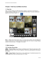
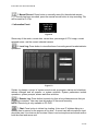
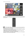
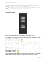
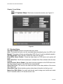
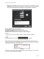
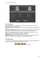
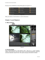
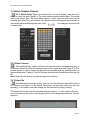
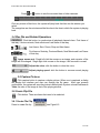
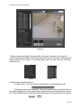
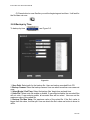
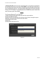
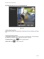
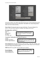
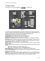
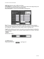
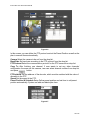
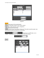
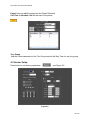
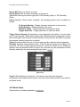
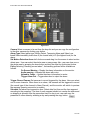
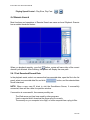
iPoint Ultra v6.01 Client User Manual
iPoint Ultra v6.01 Client
USER MANUAL
1 of 42
iPoint Ultra v6.01 Client User Manual
Table of Contents
Introduction:......................................................................................................................... 3
Chapter 1 Start Up and Main interface ...................................................................................... 4
1.1 Start Up ...................................................................................................................... 4
1.2 Main Interface .............................................................................................................. 4
1.2.1 Interface Description............................................................................................... 4
1.2.2 Local Setup ........................................................................................................... 6
1.2.3 Local Search .......................................................................................................... 6
1.2.4 Remote Setup ........................................................................................................ 6
1.2.5 Remote Search ...................................................................................................... 7
1.2.8 PTZ Control Panel ................................................................................................... 8
1.2.10 DI/DO Control .....................................................................................................11
Chapter 2 Local Setup ...........................................................................................................12
2.1 System Setup .............................................................................................................12
2.1.1 System Setup .......................................................................................................12
2.1.2 Add/Modify Server.................................................................................................14
2.2 Group Setup ...............................................................................................................15
2.3 Record Setup ..............................................................................................................17
2.4 Right Setup.................................................................................................................17
2.4.1 User Setup ...........................................................................................................18
2.4.2 Right Setup ..........................................................................................................18
Chapter 3 Local Playback .......................................................................................................19
3.1 Main Interface .............................................................................................................19
3.2 Partition Mode .............................................................................................................19
3.3 Select Playback Channel ...............................................................................................20
3.3.2 Select Camera ......................................................................................................20
3.3.3 Select file .............................................................................................................20
3.4 Play File and Related Operations ....................................................................................21
3.5 Capture Pictures ..........................................................................................................21
3.6 Create Clip File ............................................................................................................21
3.6.1 Create File Clip......................................................................................................21
3.6.2 Backup by Time ........................................................................................................23
3.6.3 View Backup File Press to View Backup File ...............................................................25
3.7 Search Captured Pictures ..............................................................................................27
3.8 Open/Close All Windows ...............................................................................................28
Chapter 4 Remote Setup........................................................................................................29
4.1 Functional Buttons .......................................................................................................29
4.2 Server Setup...............................................................................................................29
4.3 Channel Setup.............................................................................................................31
4.4 PTZ Control.................................................................................................................32
4.5 Sensor Setup ..............................................................................................................35
4.6 Alarm Setup................................................................................................................36
Chapter 5 IE Client................................................................................................................38
5.1 Functions of IE Client ...................................................................................................38
5.2 Main Interface .............................................................................................................38
5.2.1 Connection Operations ...........................................................................................39
5.2.2 Connection/Record Status.......................................................................................39
5.2.3 Partition Mode.......................................................................................................40
5.2.4 PTZ Control ..........................................................................................................40
5.2.5 Quit Program ........................................................................................................40
5.3 Local Search ...............................................................................................................40
5.4 Remote Search............................................................................................................42
5.4.1 Fast Download Record Data ....................................................................................42
2 of 42
iPoint Ultra v6.01 Client User Manual
Introduction:
Thank you for purchasing NVR client system. This NVR client system can connect via
PC-DVR (NV DVR system), EM-DVR and DVS. It can also search recorded data
remotely. In addition, the system can view server logs (only for PC-DVR) remotely. It also
supports the IE Browser to connect the DVR Client to the Server.
Please set the screen area as 1024x768 pixels before using this system.
3 of 42
iPoint Ultra v6.01 Client User Manual
Chapter 1 Start Up and Main interface
1.1 Start Up
After correctly installing the NVR Ultra Client software, a shortcut icon will show on
windows desktop. Double click to launch the NVR Ultra Client. The main interface will
appear as the follows (Figure1-1):
Figure1-1
Note: 1) When the mouse moves close to or stops over a button, text will display the
function of that button. 2) Full Screen Mode: Double-right-click mouse to change display
mode to full screen mode. Click again to turn back.
1.2 Main Interface
1.2.1 Interface Description
1. Partition Mode: Press button to set display mode. There are many types of the
partitions, including 1,4,9,16,25 and 36 partition. Select the suitable partition according to
your needs.
2. Image Capture: Press button to save a still image of a selected camera in live
view. Image will be saved on the hard drive at C://Grab
4 of 42
iPoint Ultra v6.01 Client User Manual
3. Manual Record: Press button to manually record for the selected camera.
Once the clip has been recorded, press the manual record button to stop recording. File
will be saved at C://Clip
4. Information Panel:
Figure1-2
Shows day of the week, current date, current time, percentage of CPU usage, current
selected server, and the current selected camera.
5. Local Log: Press button to view all actions of recording as well as administrator
operations:
Figure 1-3
System log keeps a record of system events such as program startup and shutdown,
camera changes and all operator or system activities. System parameters include
operations, system prompts, alarms and other activities.
6. Remote Log: Press button to search log from a long distance server that you
are being connected. User can view information of the server remotely.
NOTE: Remote log is only available to PC-DVR.
7. Chat: Press button to initiate live chatting. Voice over IP initiates dialog to a
remote client or server for the purpose of live chat. A sound card with microphone input
should be used. Live chat can not be done if there is not a microphone and sound card on
both the client and server end.
5 of 42
iPoint Ultra v6.01 Client User Manual
Figure1-4
Select a server from dropdown list to initiate remote chat.
8. System Lock: After you check “use password management” in setup, press
button to lock system. This will lock the keyboard and mouse to prevent unauthorized
user to operate NVR Ultra Client. Left-Single-Click this button to acquire the operation
rights by entering the user and password. The default user ID is “admin” and default
password is “1111”.
9. Minimize button: Press button to minimize the main window (or press WIN + Z
on keyboard).
10. Exit program: Press button to exit program. After clicking this button, a dialog
box will display. Click “OK” to quit DVR system.
Figure 1-6
1.2.2 Local Setup: Press button to enter Local setup submenu. In this menu,
user can set system and related parameters.
1.2.3 Local Search: Press button to enter Local search submenu. In this menu,
user can playback and search for recorded video/audio from local host.
1.2.4 Remote Setup: Press button to enter Remote setup submenu. In this
menu, user can set the server’s parameters remotely.
6 of 42
iPoint Ultra v6.01 Client User Manual
1.2.5 Remote Search: Press button to enter Remote search submenu. In this
menu, user can playback and search for recorded video/audio remotely. The
server-select window is as follows:
Figure1-7
Select one server from dropdown list.
Figure 1-9
1.2.6 Connection Group: Press to enter connection group setup. On this panel,
information of the displayed group and camera, Figure1-9. There are 18 preset groups
and user can choose any one group to connect. There are 36 windows that user can click
to connect all of them and click to disconnect all.
The shade of icon will show the status of window:
Group 1 connected
7 of 42
iPoint Ultra v6.01 Client User Manual
Camera Window 1-9 connects with recording.
Camera window 10-36 connected without recording.
1.2.7 Connection List: Press button to show all the equipment user has added
in this client, see Figure1-10:
The name of device connected
Figure1-10
All cameras connected to device.
Click on a camera to connect to it.
1.2.8 PTZ Control Panel
Figure 1-11
Press button to control PTZ, see Figure1-11.
1. Relay (On/Off): Controls the PTZ cameras, or relays information, used to turn on a
light or control an access gate.
8 of 42
iPoint Ultra v6.01 Client User Manual
2. Wiper (On/Off): Corresponding wiper control relay; this turns the relay/wiper on and
off.
3. Zoom + / Zoom – : Controls the zoom function of the PTZ camera.
4. Focus + / Focus – : Overrides the auto-focus setting of the PTZ camera to adjust and
focus the image.
5. Iris + /Iris – : Overrides the PTZ cameras auto-iris to brighten or darken the image.
Pressing this button initiates the PTZ camera to do an automatic 360°
tour.
Pressing and holding these buttons, the PTZ camera is moved up,
down, right, and left, as well as other directions.
6. Speed Demo
Press button and the following picture, Figure1-12, will appear (in the bottom of
main window): There are 16 preset points for the speed domes on the left and the numeric
panel on the right.
Figure1-12
7. Setup Steps: First, move speed domes to desired position. Then, input the address in
the address space (take 3 as an example here). Finally, press button. After that, the point
for 3 will be bright. User can set others the same way.
8. Delete Preset Position: Click ‘-‘ button and select the preset position number user
wants to delete from numeric panel, then click button.
9. Execute Preset Position: If preset number is less than 16, user can execute directly
by clicking the number button in PRESET ZONE. If preset number is more than 17, user
can execute by clicking number button.
10. Cruise all preset position automatically: Start Cruise: In numeric panel,
click ”-“ and the number (the interval of two preset positions). Stop Cruise: In preset zone,
click any preset position.
NOTE: On the main screen of image, user can control PTZ.
9 of 42
iPoint Ultra v6.01 Client User Manual
On window 3, each rectangle area is the effective area of every action. Arrow denotes the
direction of the action. Pressing and dragging the mouse to the corresponding area can
control the PTZ.
1.2.9 Color/Audio Adjustment: Press button to enter Color/Audio Adjust Panel.
Slide adjustments for the video image and recording volume of the selected tile. This also
affects the live view of the video images.
Press the first button at the bottom and drag to adjust the brightness of the image
that was selected. User can resume its default value.
Press the second button at the bottom and drag it to adjust the contrast of the
image that was selected. User can resume its default value.
Press the third button at the bottom and drag it to adjust the hue of the image that
was selected. User can resume its default value.
10 of 42
iPoint Ultra v6.01 Client User Manual
Press the fourth button at the bottom and drag it to adjust the saturation of the
image that was selected. User can resume its default value.
Press the fifth button at the bottom to switch sound of the audio that is related to
the image was selected. Drag the slider bar to adjust the volume.
1.2.10 DI/DO Control
Note: The channel of DI and DO is determined by the connected server 1.
1. DI Control: The DI number will show the alarm status of the corresponding server,
indicated by the shades of the icon:
Channel 3 has no sensor alarm input.
Channel 1 has a sensor alarm input.
If the alarm has not been triggered, user can press the number button to check the sensor.
Press the button again to stop. Check the time, then system check sensor according to
Sensor setup. When an alarm has been triggered, the corresponding button will turn
green.
2. DO Control: Press the number to open/close alarm device relay switch manually.
There are 2 status types for the DO:
Output channel 2 is closed.
Output channel 1 is open.
When no alarms have been triggered, user can press the number button to output alarm
manually and the button will turn green. Press it again and the output will close.
11 of 42
iPoint Ultra v6.01 Client User Manual
Chapter 2 Local Setup
2.1 System Setup: Click button to enter this window, see Figure 2-1:
Figure 2-1
2.1.1 System Setup
Save Record Mode: Sets the recorded data save mode.
Auto: The system will write over the recorded data automatically when the HDD is full.
Manual: The system will stop recording when HDD full and it must be deleted manually.
Save Begin Disk: Select the disk in which the video will save first.
Beep While Alarm: Enable: If there has been alarm on DVR server end, system will
beep.
Web Listen Port: The IE client-connect port. (Restart Ultra Client software after this item
is setup).
Alarm Connect Server Enable: If an alarm has been triggered on the DVR server end,
the client end will connect to the DVR server automatically.
Alarm Send Port: This must be the same as those in the setup window of the server
alarm auto input.
Alarm Write Log: Select whether system writes alarm information in the log or not.
Matrix Card Work Mode: If a matrix and decode card is being used, select work mode
from D1 decode mode or CIF decode mode to set.
12 of 42
iPoint Ultra v6.01 Client User Manual
Note: Each NV4002MD card can decode 2 channels D1 or 4channels CIF. Each
NV4004MD card can decode 4 channels D1 or 8 channels CIF. The decoder will
send out corresponding number channels from the first window in sequence.
User can set each output port individually.
TV Output Port: Select decoder card output port.
TV Output View Mode: Set the split mode for selected port.
Window Index of TV Port: Select the index for each split window.
Example:
This icon has four windows: window1, window2, window3, window4.
Decode channel index in window
Figure 2-3
Select window index for the selected window, see Figure2-3. Each window can only
select one decode channel. The number of decoded channels will be shown automatically
according to the channels of the decoder card.
Figure 2-4
This Figure 2-4 shows the decoded channels that have been selected. This is so that a
user can not select the decoder repeatedly.
13 of 42
iPoint Ultra v6.01 Client User Manual
Bandwidth Auto Adjust: Select whether system will adjust the bandwidth automatically.
When the window is hidden and the corresponding camera has no recorded plan, the
program will stop to connect the corresponding camera with the server to reduce CPU
usage.
Software Start Auto Connect: Select the group in Group setup to be connected when
the program starts. When you select “Disable”, the client will not connect to the cameras
automatically.
Auto Reconnect Interval: Select whether the client is to reconnect when the connection
is interrupted and the interval time. If you select “Disable” when the connection is
interrupted, the program will not reconnect.
2.1.2 Add/Modify Server, see Figure 2-5:
Figure 2-5
Add Connect Server: Press button to add a new server in this system, see Figure
2-6:
Figure 2-6
Server Name: Input a name that is easy to identify.
Device Type: Select device type you will add. This client system can connect PC-DVR
(NV DVR Server system), DVS and EM-DVR.
IP Address: Set IP address of server host.
14 of 42
iPoint Ultra v6.01 Client User Manual
Connect Port: Set the port through which it connects to the DVR Server.
Login user ID/Login Pass: When the client wants to visit the server and the server has
rights management set up, a login is required and user ID and password will be checked.
If the user has no right to visit that camera, the connection will be cut down automatically.
If the function is not used, the ID and password will not be checked.
If Use DNS to Get IP: Select whether to use DNS to get IP or not. If the server end is the
dynamic IP address, user needs to use DNS to get the server’s IP.
DNS Server IP: Set IP address of DNS server host.
DNS Server Port: DNS server host’s port, which is used to connect DNS software.
Modify Server: Press button to modify server information. Its interface is
same as Add Connected Server.
Delete Connected Server: Press button to delete connected server.
Get Camera Information: Press button to get the latest camera
information from the Server end when it changes its setups such as number of channel,
camera name etc.
Note: When you finish every setup you should save your change by pressing save button
before you exit setup.
2.2 Group Setup
Click button to enter the following window Figure 2-7:
Figure 2-7
Choose a group from the drop-list behind “Select Setup Group”. There are 16 groups. In
every group, you can set 36 connections. User can also select the partition for every
group from the drop-list behind “Partition Mode”. Then you can set group as follows:
15 of 42
iPoint Ultra v6.01 Client User Manual
IP Address Alias: Select the server in which the camera will be shown. If it does not
have a server in the drop-list, user will need to add the server in the “Server IP” page, see
Figure 2-1.
Camera: Select the camera of the server in IP Address Alias to be connected. In the
window, user can set one or more camera connections. If more than one camera is in a
window, user can set cycle interval time. User can switch them by pressing the button and
in Main interface.
Figure 2-8
Frame Rate: There are three selections: Real Time, Auto and 1FPS.
Real Time: If this is selected, the server will send all compacted information to client.
When the client gets this information, it will automatically play. However, this consumes a
lot of CPU. If there is no information lost when compacting and sending, the playing will
be real-time.
Auto: The difference between real time and auto is that some data is cut before the client
receives the information. It also consumes less CPU space. If you click any camera, the
system will adjust frame rate back to Real Time automatically.
1FPS: This means that the only one frame of information is sent to the client every second.
It consumes little network and CPU space. If you click any camera, the system will adjust
frame rate to real time automatically when there is enough network space. (NOTE: This
selection is only effective on PC-DVR).
Record Mode: There are two options: Record All Along and Record By Plan. When
users select “Record all along”, this has no effects. Record by plan will be detailed in
Record setup.
16 of 42
iPoint Ultra v6.01 Client User Manual
2.3 Record Setup
Click to enter the recorded setup interface, see Figure 2-9:
Figure 2-9
Select Window: Select the window you want to set.
Record Type: Set the type of recording, this includes Normal Record, Sensor Record,
Motion Record and No Record. You can set record type as follows:
First, press the button type that you want to set. Then select the record time by pressing
the grid (delegate 30 minutes in a day) or left-click mouse and drag for an area. If user
wants to set same record status every half hour of every day, user may double-click the
left upper corner of the chart. When you finish the setup, the grid will display the
corresponding color of the
recording type.
Green:
Normal Record
Red:
Sensor Record
Blue:
Motion Record
Gray:
No Record
Copy Record Plan To: Copy one setup to any other windows or all windows.
2.4 Right Setup
Click button to set user right, see Figure 2-10:
17 of 42
iPoint Ultra v6.01 Client User Manual
Figure 2-10
2.4.1 User Setup
Add User/Del User: Click /delete user for the Client. Afterwards, user can edit the
information for the user to be added.
Select User ID: Select a user that exists in the system to be modified from the drop-down
list.
Use Password Management: Select a solution to determine if enabled user password is
valid. When you select enable, when user is logged in a password is needed.
User ID: When adding a new user to system, input new User ID in this box. If user
selects admin in Select User ID this selection is unavailable.
Password: Set new user and selected user’s password.
Authorization Level: Select user type. When you select admin in Select User ID, this
selection is unavailable. Confirm password. Confirm password again.
2.4.2 Right Setup
You can set user management in this window, after you input user name and password, in
which user will have corresponding rights with your name.
18 of 42
iPoint Ultra v6.01 Client User Manual
Choose a user and distribute corresponding rights, see Figure 2-11:
Figure 2-11
After your selection, click the button to save the information.
Chapter 3 Local Playback
3.1 Main Interface
Figure 3-1
3.2 Partition Mode
Press corresponding button to select partition mode. There are 1, 4, 9 and 16 partition
modes. In the server end, user can only connect 16 channels simultaneously, when the
connected channels exceed the limit, the system will popup information to indicate.
19 of 42
iPoint Ultra v6.01 Client User Manual
3.3 Select Playback Channel
3.3.1 Select Date: Select one window (the 1st one in default), and then click
button to show the date Figure3-2. The white dates contain recorded data. The yellow
date is the current date. The black dates signify no data. Only the white ones can be
selected and when they are selected the camera window will appear automatically to
show which cameras has recorded data. Click
or to change month and year
of search data.
Figure 3-2
Figure 3-3
Figure 3-4
3.3.2 Select Camera
After selecting date, system will show the camera state of corresponding day, or
click button directly to show the camera’s state of the current day (see Figure 3-3). The
number button, in yellow, means this channel has recorded data. By pressing button on
the numerical panel, Figure3-3, the DVR system will play back recorded data from the first
file.
Note: Right-click the picture to perform image zoom function.
3.3.3 Select file
After selecting the camera to play, user can click the button to show all the files of
this camera, see Figure 3-4. By default, the system will play back video from the first
recording. In this screen, user can change the file they want to play by clicking.
The window below will show the recorded data user selects. To view, double click one
hour of the day and the system will play back data from the beginning of the hour from the
selection.
20 of 42
iPoint Ultra v6.01 Client User Manual
Press
or
button to see the recorded data of other cameras.
Click any minute of that hour, the system will play back that time via the window you
select.
The orange bar are the minutes and the blue bar is the time in which the system is playing
back.
3.4 Play File and Related Operations
Click this button to synchronize all playback channels time. First frame of
that day, Previous minute, Next minute and Last frame of that day.
Last frame, Start, Pause, Stop and Next frame
First frame of that day, Previous Minute, Next Minute and Last Frame
of that day.
Image zooms out: Single left click the mouse on an image, and a quarter of the
image will be enlarged. Single right click mouse on the image, it will resume to normal.
Adjust the voice: click the button to clear the voice.
Adjust playing speed: click the button to resume normal playing
speed.
3.5 Capture Pictures
Click capture button to capture a display picture. When one is captured, a dialog
will display the interface and user can change the file name. After user presses
confirmation, the system will save the picture in default path: System volume\Grab\search.
*Note: the size of the image is that of the playing window.
3.6 Create Clip File
Click button. There are items that need to be selected.
3.6.1 Create File Clip
Press to create file clip
see Figure3-5.
21 of 42
iPoint Ultra v6.01 Client User Manual
Figure 3-5
1. Select channel and path of the backup file on the top of interface, see Figure 3-5.
2. File list and attribute: Select a file and double-click (Figure 3-6) to play. Its attributes will
display below the list, Figure 3-7, including begin time, end time, file size, resolution,
frame rate, etc.
Figure3- 6
Figure3-7
3. Play file and related operations:
(1) Play control - User can press and drag slider to control the player time.
(2) Beginning and stop time setup. After user selects a time, press the button to
set as the beginning time. Then drag the bar to select as the end time and press button to
set. When finished, the file attributes on the left will show the size of the file to be created.
22 of 42
iPoint Ultra v6.01 Client User Manual
(3) Press button to save file after you set the beginning and end time. It will ask for
the file name via user.
3.6.2 Backup by Time
To backup by time
see Figure 3-8.
Figure 3-8
1. Save Path: Select path for the backup file. User can backup recorded file to CD.
2. Backup Camera: Select the backup camera. User can select more than one camera at
once.
3. Select Begin / End Time: Select the backup files’ begin time and end time.
4. Unite File: Select unite file enable or disable. If user selects disable, the recorded files
will not unite. If user selects enable, all recorded files will be united. User can set the
maximum value of the united file.
5. Backup File Max Value: Set maximum value of the united file. If the file’s value is
bigger than this value, it will be split. User can check the file’s value use button to show its
value.
23 of 42
iPoint Ultra v6.01 Client User Manual
6. Backup Data Size: Shows the size of the backup file. If user backups recorded file to
CD, the data size should not more than 650M. NOTE: If user backs up recorded files to
CD, the system disk volume’s (C volume in general) free space should not be less than
twice of the backup data size. The system volume will be used as a buffer area when
burning a CD. For example, if the backup data size is 450MB, the system volume’s free
space should be greater than 900MB.
The Process of Burning CD, see Figure 3-9:
1) Select CD-ROM as the backup path and select the camera and time.
2) Check the backup file value.
3) Backup the file to the temporary file in the last volume if there’s enough free space.
Otherwise, write backup file to the second to last volume.
4) Write back up file to buffer.
5) Write CD.
6) Delete buffer and temporary file.
Figure 3-9
24 of 42
iPoint Ultra v6.01 Client User Manual
3.6.3 View Backup File Press to View Backup File
Figure 3-10
1. Select Channel and Path
Select channel and path of the backup file in local disk on the top of interface see Figure
3-10.
2. Play file and related operations
(1) Play file and Controls: Select one from File List and double click. This file will play.
The united file is named by “date + begin time” and “date + end time”.
(2) Capture Picture: Press
(3) Burn CD: Press
button to capture picture.
button to burn CD.
25 of 42
iPoint Ultra v6.01 Client User Manual
Figure 3-11
Area 1: File directory.
Area 2: File list.
Area 3: The File directory and list will be burned to the CD.
Icon 4: Create a new directory in area
Add the file from area to area
Add selected file from area to area
Delete selected file from area.
Burn CD drive:
Select CD-ROM driver.
Label volume.
Set the CD label.
Total file size:
Shows the sizes of all files that will be burned to CD. When user finishes setup, click this
button to write file to CD. The interface is the same as
(4) Copy Player: User can press button to copy professional player for completed file to
local computer.
26 of 42
iPoint Ultra v6.01 Client User Manual
3.7 Search Captured Pictures
Click to enter the search window, see Figure3-12:
Figure 3-12
1. Select pictures from directory and file list. User can select a captured picture from
directory list see Figure 3-13 and file list Figure 3-14 in local disk. By default, the directory
is: System volume\Grab\Search. After user selects the path, the file name will show in the
top of the window.
Figure 3-13
Figure 3-14
Figure 3-15
Figure 3-15 shows name and path of current picture.
If user wants to save the reworked picture in another file, user can change its name and
path here, with bmp and jpg as suffix. Then click the save button.
27 of 42
iPoint Ultra v6.01 Client User Manual
3.8 Open/Close All Windows
Press button to open all playback windows according to the order of the
cameras.
Press button to close all playback windows.
28 of 42
iPoint Ultra v6.01 Client User Manual
Chapter 4 Remote Setup
Click button to enter remote setup, see Figure 4-1:
Figure 4-1
Select one server to search from the server list.
4.1 Functional Buttons
Are Upgrade, Restart, Time adjustment, Save and Exit.
The system can upgrade to the server remotely. Click this button and select
the right file.
Some settings will only come into effect after device reboots.
The new date and time will be in accordance to the client NVR which is
automatic.
After setup is finished, click this button to save the setup.
Exit setup.
4.2 Server Setup
Press button to set server parameters remotely
see Figure 4-3
29 of 42
iPoint Ultra v6.01 Client User Manual
Figure 4-3
In the server window, some blank cells backgrounds are gray. Those parameters are read
from the server and user can not modify them. Other blank cells, whose background is
white, user can set them remotely.
Server Name Enter the description for easy identification. This name delegates the
server. If user uses DNS to get the IP address, this address will be used.
IP Configuration and Related
Server IP
These are network configurations; user
Port
can set LAN or Internet IP according to
Subnet Mask
their needs.
Net Gate
Net Cable Type
Connection Configuration and Related Parameters
PPPOE
If system uses PPPOE to connect with web,
PPPOE Login Name
please select it and input the PPPOE login
PPPOE Login Password
ID and password.
User Password Set the user password of DVS remotely. After that operation, user
should change the Login Pass to corresponding value in Add / Modify server. Otherwise,
user can’t connect to the DVS correctly.
DNS Server IP If using DNS, input the DNS host IP address.
Remote Manage
Remote Manage IP
Remote Manage Port
Set the IP address and port of host
server who will receive the messages
uploaded from foreside server.
30 of 42
iPoint Ultra v6.01 Client User Manual
4.3 Channel Setup
Press button to set channel parameters
see Figure 4-4.
Figure 4-4
This section contains the parameters to designate a name for every camera connected, to
enable or disable, show LOGO and OSD, and to set display type of OSD & LOGO. As
well as record resolution, record type, record quality and frame rate, etc.
Camera Select the camera to be set from the drop-list.
Camera Name Enter a name description for easy identification.
Frame Rate Select the record rate of camera from drop-list.
MasStream & SubStream Select MasStream or SubStream for the current cameras.
Resolution Set the resolution at which the video files will be recorded. Choices are DCIF,
CIF, QCIF, 2CIF and 4CIF. The higher the resolution, the more disk space will be used.
Stream Type Select video and audio or only video record.
Image Set the quality of the image to be recorded. Select from Worst, Worse, Normal,
Good and Best.
Bit Rate Type Select bit rate type from Variable Bit Rate (VBR) and Fixed Bit Rate (FBR)
record:
VBR range= Poorest, Poor, Medium, Good, Best.
FBR range = 45 Megabytes/Hour to 400 Megabytes/Hour.
Max Bit Rate Select the maximum bit rate for Variable Bit Rate (VBR) record.
Show LOGO/OSD/Week If you check these boxes, the system will show corresponding
information on the screen.
Position Set the position of OSD or Logo by entering the X and Y to coordinate directly.
OSD Set the display attribute of the OSD & LOGO. There are four types of display modes:
Clarity-Glitter, Clarity-Not Glitter, Not Clarity-Glitter and Not Clarity-Not Glitter.
31 of 42
iPoint Ultra v6.01 Client User Manual
OSD Type Select the type of OSD for the Week.
Privacy Mask You can check this box to set the privacy mask on the image directly, and
you can clear some privacy masks by pressing button.
Record Schedule You can set record schedule in following chart:
Note: This record schedule is only available to EM-DVR. There are 4 time segments
every day. Every segment has a start time, end time and record type. The time segment is
set in sequence. Segments can not be overlap, include or skip each other.
Copy To After finishing one channel, if you want to set any other channels’ configuration
as the same as this camera, you can select channel number from drop-list, and press
copy
button.
Set the time to record.
4.4 PTZ Control
Press button to set PTZ
see Figure 4-6
32 of 42
iPoint Ultra v6.01 Client User Manual
Figure 4-6
In this screen, you can define the PTZ protocol and set the Preset Position as well as the
plan to execute them automatically.
Camera Select the camera to be set from the drop-list.
Baud Rate Set baud rate according to the PTZ protocol from the drop-list.
PTZ Protocol Select the communication protocol for the PTZ camera from drop-list.
Copy To After finishing one channel, if user wants to set any other channels’
configuration the same as this camera, user can select channel number from drop-list,
and press
button.
PTZ Address Set the address of the decoder, which must be matched with the value of
dipswitch in the PTZ.
Speed Set the speed of the PTZ.
Preset Position & Schedule Setup Define preset position and set time to call preset
position automatically. System can add and delete plan time.
Figure 4-7
33 of 42
iPoint Ultra v6.01 Client User Manual
Figure 4-8
Name Set the name for the current preset.
Preset Set the preset number for the current camera.
Set Up the preset by current configuration.
Delete the finished Preset.
Call the Preset if the Mode is Call preset. The mode is saved in preset, user
should save the preset and shouldn’t call the preset.
When there is no PTZ action, set to
“disable”. Afterwards, the PTZ will come back to the home position.
34 of 42
iPoint Ultra v6.01 Client User Manual
Preset User can add the preset into the Preset Schedule.
Call Time & Schedule List Set the time of the preset.
Tour Group
Add the Preset cameras into the Tour Group and set the Stay Time for one tour group.
4.5 Sensor Setup
Press button to set sensor parameters
see Figure 4-9.
Figure 4-9
35 of 42
iPoint Ultra v6.01 Client User Manual
Sensor NO Select one sensor to be set.
Sensor Name Enter the name description of the sensor.
Type Select alarm type (sensor type) from “NO”(Normally Open) or “NC”(Normally
Close).
Policy Selecting “Sensor Alarm Handling”, the handling policies will be available as
follows:
On Screen Warning – Display the alarm information on the monitor.
Audio Warning – Indicate the alarm with voice.
Upload to Center – Update the alarm information to center.
Trigger Alarm Out – Trigger alarm box to output the alarm.
Trigger Record Camera Set cameras to record triggered by the alarm. You can select
one or more channels. When there is alarm input, the cameras will be triggered to record
(the record type of the channel is Alarm Record), and the monitor will switch to preview
the cameras (warning on monitor is enable).
Preset Set camera that will move to its one preset position when the alarm happened.
Schedule Set alarm input precaution time. Then set the time segment according to the
sequence. The time of each segment should not overlap the others and no skipping is
allowed. After the precaution time of a day is set, user can copy the parameters to other
dates by selecting a day and pressing the copy button.
Figure 4-10
Copy To After finishing one channel, if user wants to set any other channels’
configuration as the same as this camera, user can select channel number from drop-list,
and press button.
4.6 Alarm Setup
Press button to set alarm parameters.
36 of 42
iPoint Ultra v6.01 Client User Manual
Figure 4-11
Camera Select a camera to be set from the drop-list and you can copy the configuration
to the other cameras by clicking copy button.
Alarm Type Select alarm type: Motion Detect, Tempering Alarm and Video Loss.
Level Select sensibility levels from 0 (the lowest level) to 5 (the highest level) for the
alarm.
Set Motion Detection Areas Left-click mouse and drag it on the screen to select motion
detect area. User can select the whole area or many areas. Also, user can clear one or
the whole area by pressing the clear button and test the effect by clicking test button.
Policy Selecting “Handling current alarm”, the handling policies will be available as
follows:
On Screen Warning – Display the alarm information on the monitor.
Audio warning – Indicates the alarm with voice.
Upload to Center – Update the alarm information to center.
Trigger Alarm Out – Trigger alarm box to output the alarm.
Trigger Record Camera Set cameras to record triggered by the alarm. User can select
one or more channels. When there is an alarm, the cameras will be triggered to record
(the record type of the channel is Alarm Record), and the monitor will switch to preview
the cameras (warning on monitor is enable).
Schedule Set alarm input precaution time. Select date first, then set the time segment
according to the sequence. The time of each segment should not overlap the others and
no skipping is allowed. After the precaution time of a day is set, user can copy the
parameter to other dates by selecting a day and pressing the copy button.
37 of 42
iPoint Ultra v6.01 Client User Manual
Figure 4-12
Copy To After finishing one channel, if user wants to set any other channels’
configuration the same as this camera, user can select the channel number from drop-list,
and press the copy button.
Chapter 5 IE Client
The client user can view video from the Surveillance Server through Internet Explorer.
The default web server port is 80. If a user changes it to another port, the user should add
this port number after the domain name when visiting the Surveillance Server through
Internet Explorer. Ie: http://192.168.0.119:1280.
5.1 Functions of IE Client
1. Video display and video storage
2. Audio input
3. Search and playback video images locally or remotely
4. Control PTZ and speed dome cameras remotely
5.2 Main Interface
When user connects to the Surveillance Server successfully, user should input a valid
User ID and Password to acquire rights to play video and other operations.
38 of 42
iPoint Ultra v6.01 Client User Manual
5.2.1 Connection Operations
Select the Stream type for the current cameras.
Press
to connect to the Surveillance Server’s cameras. Select
to view video from Surveillance Server. Press will
disconnect all
connections. If Surveillance Server’s channels are more than the channels that user
selected for partition mode, user can use
button to display Surveillance Server’s video
in sequence. Pressing
button will switch full screen mode and Right-Single-Click
image can back to normal mode.
5.2.2 Connection/Record Status
This icon indicates the current connection and their record status:
Gray:
Blue
Green:
Not connected
Connected with no recording
Connected with recording
39 of 42
iPoint Ultra v6.01 Client User Manual
You can change the record status by pressing corresponding number button or change
status of all connections at the same time by pressing
button.
5.2.3 Partition Mode
User can set the partition mode by pressing corresponding buttons on the right of the
main interface. The system has follow partition modes:
1
1 Partition Mode
4 Partition Mode
4
6 Partition Mode
9 Partition Mode
10 Partition Mode
16 Partition Mode
5.2.4 PTZ Control
Most functions of PTZ control are the same as PTZ Control panel in Surveillance Server.
5.2.5 Quit Program
Press
button to shut down the IE Client.
5.3 Local Search
Press
button to enter local search:
40 of 42
iPoint Ultra v6.01 Client User Manual
1. Display Setup and Data Information
In this area, user can select display partition mode, date, video channel and its video file
named according to time.
2. Playing Operation Area
In this area, user can operate video playing:
Video Playing- Time Adjustment. Press and drag slider bar to adjust video
playing time
Information Display Panel- Display current window name, camera name and
recorded data information.
Playing- Control Buttons- Play, Pause, Stop.
Single Frame Play- Previous Frame, Next Frame
41 of 42
iPoint Ultra v6.01 Client User Manual
Playing Speed Control - Play Slow, Play Fast
5.4 Remote Search
Most functions and operations of Remote Search are same as Local Playback. Remote
has an added download feature
When you playback remotely, you click
button, system will save video of the current
channel you selected. After finishing, the system will display the save path.
5.4.1 Fast Download Record Data
In the playback mode, select one camera that has recorded data, open the file in the list
panel, select one recorded data file, and click
button, and the selected data
file will download.
NOTE: When a user uses IE client to visit the Surveillance Server, if successfully
connected, there will be a blue four partition window.
If connection is unsuccessful, the reasons possibly are:
The Web server port has been used by other programs.
User’s computer didn’t download the player plug-in correctly.
The security on you computer is too high, or users computer has a plug-in filter.
42 of 42