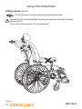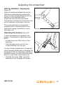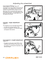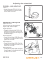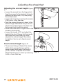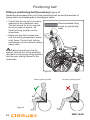
1
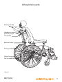
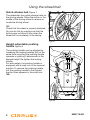
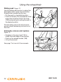
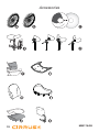
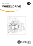
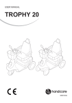
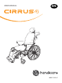
Cirrus 4
USER MANUAL
EN
MB3170-EN-C
Introduction
Congratulations on your choice of new wheelchair.
Quality and functionality are the key concepts for all the wheelchairs in the
Handicare range.
For your own safety, and in order for you to get the best possible benefit from the
features of your new wheelchair, we recommend that you read this user manual
carefully before you start to use the wheelchair.
Cirrus 4 in brief
Cirrus 4 was developed with special consideration for the fact that users have
different needs and wishes, whether the chair is to be used simply as a comfort
wheelchair or will be driven by the user. As the seat height is adjustable, it is also
very suitable for people who use one or both legs to propel the chair forward.
The wheelchair can be dismantled, and features removable leg supports and a
collapsible backrest which make it easy to transport. Good rolling characteristics
are combined with a safe and reliable chair. The design is anatomically correct, so
that it is comfortable to sit in. The chair is virtually maintenance-free.
This user manual is for Cirrus 4
with serial number: . . . . . . . . . . . . . . . . . . . . . . . . . . . . . . . . . . . .
The wheelchair was inspected and approved
on:. . . . . . . . . . . . . . . . . . . . . . . . . . . . . . . . . . . . . . . . . . . . . . . . .
by:. . . . . . . . . . . . . . . . . . . . . . . . . . . . . . . . . . . . . . . . . . . . . . . . .
www.handicare.com
2
MB3170-GB
Contents
Introduction...................................................................................2
Contents ........................................................................................3
Wheelchair parts ..........................................................................4
Assembly .......................................................................................6
Using the wheelchair....................................................................8
Adjusting the wheelchair ...........................................................17
Positioning belt ...........................................................................24
Safety ...........................................................................................25
Safety in cars ..............................................................................27
Maintenance ...............................................................................30
Technical specifications ............................................................33
Labelling ......................................................................................35
Accessories ................................................................................36
Guarantee....................................................................................38
MB3170-GB
3
Wheelchair parts
In order to be able to properly understand this manual, it is important that you
are aware of the commonest terms used to describe the various parts of the
wheelchair. Examine the drawings below and on the following page, and note the
relevant parts on your wheelchair.
The equipment on your wheelchair may vary slightly from that shown in Figures
1 and 2. If Cirrus 4 has been set up as a helper-guided chair, it is equipped with
different wheel sizes, as well as a brake lever for the assistant on the pushing
handle.
Head and neck support
Backrest cushion
Armrest
Seat cushion
Leg support
Footplate
Front castor wheel fork
Brake
Adjustment handle
for sliding seat
Front castor wheel
Figure 1
4
MB3170-GB
Wheelchair parts
Pushing handle
Handle for
backrest angle
Tilt handle
Backrest shell
Driving wheel
Hand rim
Anti-tip stabiliser
Figure 2
MB3170-GB
5
Assembly
Assembly
As standard the wheelchair is supplied
fully assembled.
The only things you need to do are:
• Raise the backrest
• Fit the armrests
• Fit the leg supports
Raise the backrest Figures 3, 4 and
5
• Pull out the bolt (3A)
• Locate the wires between the brackets
as shown in Figure 4. Place the bar
for the adjustment mechanism into the
bracket and replace the bolt
• Pull out the bolt (4A). Place the bar for
the pneumatic spring into the bracket
and replace the bolt, as shown in
Figure 5
• You can now raise the backrest to the
desired position. See page 9 for details
of how to adjust the sitting position by
changing the backrest angle and tilt
A
Figure 3
A
Figure 4
Figure 5
6
MB3170-GB
Assembly
Fitting the armrests
• Fit the armrest as shown in Figure
6. If the locking pin (6A) does not
lock properly, move the back armrest
fixing (6B) inwards or outwards until
the locking pin goes into the locked
position.
• Push down the locking handle (6C)
B
C
Figure 6
MB3170-GB
A
7
Using the wheelchair
Quick-release hub Figure 7
The wheelchair has quick-release hubs on
the driving wheels. Press the button in the
middle of the driving wheel to remove or
locate the driving wheel.
NB!
Check that the wheel is properly fastened.
You can do this by making sure that the
button pops out about 5 mm when the
wheel bolt is completely in the casing.
Figure 7
Height-adjustable pushing
handle Figure 8
The pushing handle can be adjusted by
loosening the locking handles (8A) at the
same time as pulling the pushing handle
upwards or pushing it downwards to the
desired height. Re-tighten the locking
handle.
For extra safety, the pushing handle is
equipped with a snap lock in the topmost
position. To remove the pushing handle,
pull the pushing handle to the highest
position then squeeze in the snap lock
(8B).
A
B
Figure 8
8
MB3170-GB
Using the wheelchair
Changing the sitting position by
adjusting the backrest and seat
angle Figures 9, 10 and 11
• Adjust the backrest angle with the left
adjustment lever (9A) (see Figure 10)
• Tilt the chair with the right adjustment
lever (9B) (see Figure 11)
For safe adjustment of the sitting position
the assistant should grip firmly on the
pushing handle with one hand, and
operate the adjustment levers with the
other hand.
A
B
Figure 9
An extra adjustment lever for useroperated adjustment of the backrest angle
is available as an accessory.
The chair might be unstable when
the backrest and the seat are angled
in the backmost position.
The anti-tip stabiliser should be
used when the sitting position is
leaning backwards.
Figure 10
MB3170-GB
Danger! Ensure that hands
and other body parts are not
squashed when tilting the
chair
Figure 11
9
Using the wheelchair
Sliding seat Figure 12
Use the sliding seat function to adjust the
seat depth and to move the seat further
forward when transferring the user.
• Put the seat in a horizontal position
• Push the handle (12A) backwards at the
same time as taking hold of the strap
(12B) and pushing or pulling the seat to
the desired position
Pull the sliding seat to the fully-forward
position when transferring into and out of
the chair.
A
B
Figure 12
Armrests, remove and replace
Figure 13
• Squeeze in the snap lock (13A) to
loosen the back edge of the armrest
• Push up the release handle (13B)
• Lift up the armrest
A
See page 7 for how to fit the armrests.
B
Figure 13
10
MB3170-GB
Using the wheelchair
Swing out / fit / remove the leg
supports Figures 14 and 15
The leg supports can be swung out or
in, and are removable for easier transfer
and transport. Release the leg support
by turning the handle (14A) inwards or
outwards so that the leg support is swung.
A
The entire leg support unit with its fixing
can be removed (see page 18).
Figure 14
Figure 15
Full footplate (Standard on Cirrus
X chairs) Figure 16
The full footplate can be split in two and
tipped up for transfers. Ensure that the
footplates lock in place when you put them
back down.
The footplates lock most easily into place if
they are angled right in to each other when
you put them back down (see figure 16).
Figure 16
MB3170-GB
11
Using the wheelchair
Using the brakes Figure 17
Pull the brake lever towards you to lock the
brake. The brake locks both driving wheels
at the same time.
The brake is constructed only to keep
the chair from moving. Under no
circumstances may it be used as a
driving brake.
Figure 17
Use of the brakes on Cirrus 4
with the assistant brake (the
assistant brake is standard on
helper-guided chairs, otherwise
is available as an accessory) .......
A
Figure 18
• Squeeze the brake handle (18A) to
brake
• Push the release handle (18B) away
from you to lock the brake in position
when parking. Squeeze it in to unlock
the brake
12
B
Figure 18
MB3170-GB
Using the wheelchair
Folding Cirrus 4 for transport
Figure 19
Fold up Cirrus 4 so that it takes up the
least space possible during transport.
• Remove the armrests
• Remove the leg supports
• Remove any optional equipment
• Remove the pushing handle and turn it
around
• Remove the seat cushion
• Remove the driving wheels
• Fold down the backrest
Figure 19
Folding down the backrest
Figure 20
• Move the backrest completely forward
• Pull out the bolts for the pneumatic
spring and the adjustment mechanism.
Immediately replace the bolts to avoid
losing them
• Fold the backrest down completely
Ensure that the wires lie between the
brackets on the inside of the bolt at
all times to avoid breaks.
MB3170-GB
Figure 20
13
Using the wheelchair
Transfer into and out of the chair
Figures 21, 22 and 23
•
•
•
•
Engage the brakes
Swing out or remove the leg supports
Tilt the chair forwards
Use the sliding seat to move the user as
far forwards in the chair as possible (see
Figure 12, page 9)
• The user can now be transferred out of
or into the chair with the help of manual
lifting or lifting equipment, or transferred
from the front.
Figure 21
Figure 22
Figure 23
14
MB3170-GB
Using the wheelchair
Negotiating obstacles: steps
Figures 24 and 25
When the wheelchair is to be lifted up or
down steps with the user in the chair, if at
all possible use the recommended lifting
points. These are marked on the product.
See Figure 26.
Ensure that the pushing handle is locked
before you lift.
In order to give the assistants a better
lifting position, they can if necessary lift
with one assistant on each side of the
chair.
Figure 24
Negotiating obstacles: kerbs
Figure 25
Figure 26
When you need to climb kerbs etc., if
necessary push up the anti-tip stabiliser.
Then put one foot on the tipping bar, at the
same time as controlling the chair with the
pushing handle. Tilt the chair backwards
if necessary to get sufficient clearance
between the obstacle and the leg supports.
Steep terrain
If you frequently use the chair in hilly
terrain, we recommend that the assistant
brake be installed
Figure 26
MB3170-GB
15
Using the wheelchair
Lifting points Figure27
The lifting points are the pushing handle and the frame.
Ensure that the locking handles on the pushing handle are well tightened
before you lift!
Do not use the armrests to lift the wheelchair!
Figure27
16
MB3170-GB
Adjusting the wheelchair
Anti-tip stabiliser / tipping bar
Figure 28
Adjust the distance between the anti-tip
stabiliser and the base by pressing the
snap lock and pulling/pushing the anti-tip
stabiliser to the desired position.
Check that the snap lock has locked.
The maximum distance from the end of the
anti-tip stabiliser to the base is 35 mm.
The anti-tip stabiliser is as standard
equipped with a clearance down to the
base which makes it possible to mount
doorsteps, etc.
Figure 28
Adjusting the brakes Figure 29
If small adjustments are needed to the
brakes, it is sufficient to adjust the brake
block.
• Loosen the screw (29A) with a 4 mm
Allen key
• Twist the brake block until it is the
correct distance from the tyre.
In case of larger adjustments, for example
when changing wheel type or changing the
placement of the driving wheels’ position in
the wheel frame, you must move the brake
block to a new hole in the brake fixing.
• Unscrew the screw (29A), move the
brake block and re-tighten the screw
MB3170-GB
A
Figure 29
17
Adjusting the wheelchair
Leg support fixing Figure 30
The depth of the leg support fitting can be
adjusted or the support can be removed.
Loosen the screw (30A) using a 4 mm
Allen key. Pull or push the leg support to
the desired position. The leg support fitting
must not be pulled out more than 8 cm.
Re-tighten the screw.
A
Figure 30
Legrest – angle adjustment
Figure 31
A
The legrests can be adjusted separately.
• Loosen the locking handle (31A)
• Adjust the legrest to the desired angle,
and tighten the handle
Figure 31
Leg support – length adjustment
Figure 32
• Squeeze in the snap lock (32A) in the
square-profile tubing at the same time
as pulling or pushing the footplate to the
desired length
A
Figure 32
18
MB3170-GB
Adjusting the wheelchair
Footplate – angle adjustment
Figure 33
• Loosen the screw (33A) with a 5 mm
Allen key. Adjust to the desired angle
and re-tighten the screw
A
Figure 33
Adjustment of calf supports
Figures 34 and 35
The calf support can be adjusted for
height, angle, width and depth.
Height adjustment
• Squeeze in the snap lock (34A) in the
square-profile tubing at the same time
as pulling or pushing the calf support to
the desired height
Depth adjustment
• Loosen the lock wheel (34B). Move the
calf support to the desired depth and retighten the lock wheel
A
B
Figure 34
Angle adjustment
• Loosen the lock wheel (35A). Twist the
calf support to the desired angle and retighten the lock wheel
A
Width adjustment
• Loosen the lock wheel (35A). Push/pull
the calf support to the desired width and
re-tighten the lock wheel
Figure 35
MB3170-GB
19
Adjusting the wheelchair
Adjusting the balance point
Figures 36 and 37
The centre of gravity is adjusted by moving
the wheel to another position on the wheel
fastening. The wheel fastening has three
holes. The back holes make the chair most
safe with regard to tipping, whereas the
front holes make the chair easier to roll.
20” and 22” driving wheels can be placed
in any of the three holes, but 24” driving
wheels can only be placed in the two
backmost holes.
20” and 22”
24”
Figure 36
Always adjust the brakes after you
have adjusted the balance point!
• Remove the driving wheel
• Loosen the wheel casing by unscrewing
the outward nut (37A) with a 24 mm
spanner while restraining the inward nut
with a 24 mm spanner
• Move the wheel casing to the desired
hole and screw the nut on again
• Put the driving wheel back on
A
Figure 37
20
MB3170-GB
Adjusting the wheelchair
Adjusting the height of the
backrest Figure 38
The backrest of Cirrus 4 can be raised or
lowered.
• Remove the backrest cushion
• Remove the plastic plugs on the screws
(38A)
• Loosen the screws on the inside of the
backrest shell with a 5 mm Allen key
while restraining on the outside with a 10
mm spanner
• Raise or lower the backrest shell to the
desired position
• Screw the screws back in again and
replace the backrest cushion
A
Figure 38
A
Adjusting the head and neck
support (accessory) Figure 43
Depth adjustment
• Loosen the locking handles (43A), make
the adjustment and tighten the locking
handles again
Height adjustment
• Unscrew the locking wheel (43B), raise
or lower the neck support and tighten the
locking wheel again
MB3170-GB
B
C
Figure 43
21
Adjusting the wheelchair
Adjusting the armrest height Figure
41
• Loosen the armrest from the hinge which
fixes the armrest to the backrest tubing by
pressing the snap lock (41A) and pulling
the armrest down
• Loosen the hinge by loosening the screws
(41B) with a 4 mm Allen key
• Push the armrest hinge up or down to the
desired height. Make sure that you do not
adjust the armrest hinge so far down that
the armrest fouls the driving wheel
• Screw the screws back in again and fix the
armrest to the bracket
• Loosen the handle (41C) and adjust the
height at the front. Ensure that the handle
has locked into place when you have
adjusted the armrest height. See below
for details of how to set a fixed armrest
height.
A
Figure 41
A
Fixed armrest height Figure 40
• The armrest tubing is fitted with a sleeve
(40A) which ensures that you get the
same armrest height each time, even if
you lift, remove or replace the armrest.
Adjust the sleeve up or down by loosening
it with a 4 mm Allen key.
22
B
Figure 40
MB3170-GB
Adjusting the wheelchair
Adjusting the seat width Figure 42
The seat width can be adjusted by changing the fixing points of the armrests.
The various Cirrus models can be adjusted to the following seat widths:
•
•
•
Model
Seat width
Cirrus 4 Narrow/Cirrus K
34 - 41 cm
Cirrus 4 Wide
41 - 48 cm
Cirrus 4 X-Wide
48 - 55 cm
Cirrus 4 X 65
60 - 67 cm
Cirrus 4 X 70
65 - 72 cm
Loosen the screws (A)
Push the arm rest pad inwards or
outwards
Make the equivalent adjustment on the
opposite side and tighten the screws
A
Figure 42
MB3170-GB
23
Positioning belt
Fitting a positioning belt (accessory) Figure 43
Handicare recommend that you fix the positioning belt around the sections of
tubing which are shaded grey in the diagram below.
• Check that the hip belt is correctly
adapted to the wheelchair user.
The belt should lie firmly over the
hip at an angle of approx. 45°
from the fixing position on the
wheelchair.
Recommended fixing
points for positioning
belts
• Make sure the belt is clean and
that the locking mechanism works
at all times. The belt and locking
mechanism can be cleaned using a
damp cloth.
Placing the belt over the hip,
against the soft skin of the stomach,
can result in the wrong sitting position
and the user sliding forward in the
wheelchair.
Figure 43
Correct placing of belt
Incorrect placing of belt
45˚
Figure 44
24
MB3170-GB
Safety
• Do not stand, or exert great pressure, on the footplates
• A wheelchair should be viewed as a replacement for walking. Users must
therefore move among pedestrians, not on roads or streets with motorised
traffic. Use reflectors when using the wheelchair outdoors
• When transferring yourself out of the chair, take care to ensure that you are
on as stable and even a surface as possible. To ensure that the chair does not
move when you don’t want it to, check that the brake is engaged and locked
• The maximum user weight for Cirrus 4 is 140 kg (Cirrus 4 X 175 kg).
• You should visually inspect the chair regularly to assure yourself that all screws,
bolts and other fixing devices are securely fastened
• When the chair is in use, always ensure that the anti-tip stabiliser is in the
correct position
• If any modifications are made to the chair, such as moving the driving wheels or
front castor wheels, changing the backrest height etc., this can affect the chair’s
driving characteristics, balance and tipping point. Exercise particular care when
you start to use the chair again
• Avoid making modifications or alterations to the chair which may affect the
safety which is built in to the chair’s construction
• The use of qualified helpers is recommended when transferring into and out of
the chair
• Take care that clothes, baggage and other loose items do not get tangled up in
the wheel spokes
• Be aware of the possible danger of crushing injury: avoid putting your fingers
between the clothing guard and the wheel, and between the wheel and the
brake
• If while using the chair it is necessary to raise the front of the chair to negotiate
an obstacle, never do this solely by pressing down on the pushing handles.
Step on the tipping bar while using moderate pressure on the pushing handles
• Sitting in the wheelchair for a long period of time increases the danger of
pressure sores. If there is a high risk of pressure sores, we recommend the use
of a special seat cushion to avoid this
MB3170-GB
25
Safety
Reflectors Figure 45
Use reflectors when using Cirrus 4
outdoors. See Figure 45 for reflector
locations.
Figure 45
26
MB3170-GB
Safety in cars
Fastening in a vehicle
Figures 46 and 47
Wheelchair users should transfer to the vehicle seat and use the vehiclemanufacturer-installed restraint systems whenever it is feasible, and the
unoccupied wheelchair should be stored in a cargo area or secured in the vehicle
during travel.
The wheelchair can be used as a passenger seat in a car and has been tested in
accordance with ISO 7671/19.
When the wheelchair is used as a passenger seat it should sit facing forward.
The wheelchair must be attached to the fastening system it was tested for;
The system is a 4-point fastening system. The system is a total
system that fastens both the wheelchair and user to the car. The
system requires fastening rails to be mounted in the car.
User restraint system: 3 point shoulder and hip belt.
Cirrus 4 has four points marked out (46) which must be used to
strap down the chair.
Figure 46
Figure 47
Handicare takes no responsibility for the use of Cirrus 4 as a passenger
seat in a vehicle if any fixing system other than those named above has
been used.
Cirrus X should not be used as a seat in motorised vehicles
MB3170-GB
27
Safety in cars
Fastening the seat belt:
• The pelvic-belt restraint must be
fastened at as steep an angle as
possible; between 30° and 75°
• The shoulder-belt restraint is fastened
over the shoulder and chest
• The seat belt is fastened as tightly to
the body as possible and must not be
twisted
• Make sure the belt restraints is not kept
away from the body by the wheelchair
parts, such as armrests and wheels.
For correct positioning, see figure
below
• The chair must not be tilted backwards
when used as a passenger seat
in a car
Figure 48
Make sure that the seat
belt is not kept away from
the body by the wheelchair
parts, such as armrests
and wheels.
WARNING
a) Where possible, the wheelchair should be in a forward facing
direction and secured in accordance with the instructions from the
manufacturer of the fastening system.
b) This wheelchair is approved for use in cars and meets the
requirements for forward facing transport and head on collisions.
The wheelchair has not been tested for other positions in a
vehicle.
c) The wheelchair has been dynamically tested in a forward facing
direction, with the user secured by both a stomach and chest belt
(3-point seat belt)
28
MB3170-GB
Safety in cars
d) Both the stomach and chest belts should be used to reduce the
risk of head and chest injuries in the event of colliding with parts
in the car.
e) In order to reduce the risk of injury to the user, tables that are
fitted to the wheelchair, which are not designed for crash safety,
must be:
• Removed and secured separately in the vehicle, or
• Secured to the wheelchair, but with energy-absorbing padding
placed between the table and the user
f) Where possible, other wheelchair accessories should be secured
to the wheelchair or removed from the chair and secured in the
vehicle during transport, so that they don’t become loose and
cause injury to the user in the event of a collision.
g) Support and positioning equipment must not be regarded as
safety equipment/seat belts if they are not labelled in accordance
with the requirements of ISO 7176/19-20XX.
h) The wheelchair should in inspected by a representative of the
manufacturer before being used again after any kind of collision.
i) No changes or replacements must be made to the anchorage
points/car fastenings on the wheelchair, or to constructional
elements or parts of the frame without consulting the
manufacturer.
j) When using electric wheelchairs in motor vehicles, gel-filled
batteries should be used.
MB3170-GB
29
Maintenance
The maintenance described in this section can be carried out by the user.
Other maintenance work should be carried out by qualified personnel at
your local supplier or at the technical aids centre. For information about
repairs or service, ask the technical aids centre in your area.
Washing the frame
The frame should be regularly washed with mild soapy water. If the frame is
very dirty, a scouring agent may be used. If necessary, the frame can be flushed
using a high-pressure jet spray. Try to avoid spraying directly at the ball bearings.
Dry the wheelchair thoroughly after washing or when it has been out in the rain.
Grease all moving parts if you have used a scouring agent.
Cleaning the seat and backrest covers
The covers can be washed in a washing machine at 60 °C. See the washing
instructions on the various textiles.
Conditions which may damage the wheelchair
The chair should not be used in temperatures below –35 °C or over 60°. No
requirements are specified in connection with humidity and air pressure. No other
requirements are specified for storage.
Screws and nuts
Screws and nuts can loosen over time. Therefore, remember to check and if
necessary tighten them at regular intervals. A screw locking agent such as Blue
Locktite (no. 243) may be used. If a locking nut has been removed, it loses some
of its locking properties and should be replaced.
Lubrication
Moving parts, such as the rails on the sliding seat, should be lubricated as
needed.
Driving wheels
The driving wheels are equipped with spokes. These should be adjusted if they
begin to work loose. Ask a local bicycle dealer or your nearest technical aids
centre.
Quick-release hub for the wheels
The quick-release hub for the driving wheels requires regular inspection. Check
that the ball bearings are working satisfactorily. The release bolt and ball bearings
should be cleaned and lubricated with oil regularly.
30
MB3170-GB
Maintenance
Recommended air pressures
The chair can be supplied with solid or pneumatic wheels.
Find the correct type and size of driving wheel or castor wheel, then read off the
recommended maximum air pressure from the table. Note that a high air pressure
makes the chair easier to roll, while a lower air pressure gives a softer ride.
For optimal driving characteristics, the air pressure should be checked regularly.
kPa
Bar
PSI
Driving wheels, pneumatic tyres
350
3,5
50
Driving wheels, high pressure
630
6,3
90
Castor, 6” pneumatic tyres
250
2,5
35
Castor, 8” pneumatic tyres
250
2,5
36
Tools for service and maintenance of the wheelchair
Adjusting:
Tool(s):
Bremser
4 mm Allen key
Footplates
5 mm Allen key
Armrest height
4 mm Allen key
Driving wheel
position
24 mm spanner (x2)
Backrest height
5 mm Allen key and 10 mm spanner
Seat width
3, 4 and 6 mm Allen keys and No. 3 Philips screwdriver
Inspect after six months, and then every year
•
•
•
•
Check that the brake works correctly. Adjust if necessary
Check that the tyres are in good condition, with no damage to the sidewalls
See that the chair is clean and that all moving parts work correctly
Check and if necessary adjust all screwed joints
MB3170-GB
31
Maintenance
Repairs
Apart from minor repairs to the paint, changing the tyres or inner tubes, and
adjusting the brakes, all repairs must be carried out by qualified personnel at your
local supplier or at the technical aids centre.
For information about repairs or service, ask the technical aids centre in your
area.
Changing pneumatic tyres
Figure 49
B
Pneumatic tyres are accessories
Removing the tyre
• Take off the wheel, then deflate the tyre
by holding down the small pin in the
valve, or by unscrewing the valve out
completely
• See that the edge of the tyre is well down
in the inward side of the rim (49A)
• Bend the edge of the tyre over the edge
of the rim. Use a special tyre lever (49B)
if necessary. Ensure that the inner tube
does not get squeezed between the lever
and the edge of the rim
C
A
Figure 49
Fitting the tyre
• Put the inner tube into the new tyre and
apply an anti-friction agent (tyre fitting
agent or soap) to the edge of the tyre
(49C)
• See that the edge of the tyre is well down
inside the rim on one side. Bend the tyre
over the edge. Ensure that the inner tube
does not get squeezed
• Inflate the tyre to the correct pressure
and fit the wheel to the chair
32
MB3170-GB
Technical specifications
Technical specifications and measurements
Cirrus 4 is supplied in four different seat widths: narrow, wide, extra wide and
Cirrus K. Ask for advice at your dealer or at your nearest technical aids centre
if you are unsure whether you have the correct width. (All measurements are in
centimetres unless otherwise stated. The stated measurements may vary by +/– 1
cm).
Narrow
model
Wide
Model
Extra
Wide
model
X
-65
X
-70
Cirrus K
Seat width
34 - 41
41 - 48
48-55
60- 67
65 - 72
34 - 41
Seat height
48 (42-53)
48 (42-53)
48 (42-53)
48 (42-53)
48 (42-53)
38 (38-48)
Seat depth
45 - 60
45 - 60
45 - 60
45 - 60
45 - 60
32 - 43
Backrest height
63-67
63-67
60-64
60-64
60-64
53-57
Backrest angle
75° / 135°
75° / 135°
75° / 135°
75° / 135°
75° / 135°
70° / 132°
Seat angle
-5° / 18°
-5° / 18°
-5° / 18°
-5° / 18°
-5° / 18°
-5° / 15°
Total height
103
105
105
105
105
90 - 97
Total width
Seat width
+ 20 cm
Seat width
+ 20 cm
Seat width
+ 20 cm
Seat width
+ 20 cm
Seat width
+ 20 cm
Seat width
+ 20 cm
Total length
114
114
114
106
106
100
Weight of chair
32,4 kg
33,6 kg
35,5 kg
45
48
26
Transport width
58
65
72
81
86
58
Transport height
67
67
67
67
67
62
Transport
weight
15
18
18,7
21
25
27
Max. user weight
140
140
140
175
175
100
MB3170-GB
33
Technical specifications
The wheelchair is made of steel and aluminium. The backrest and seat cushions
are covered in flame-retardant materials. The front and driving wheels can
optionally be supplied with solid or pneumatic tyres.
Under normal use and with prescribed maintenance, the wheelchair’s expected
lifespan is approximately seven years.
Areas of use
Cirrus 4 is suitable for both indoor and outdoor use. The chair has been developed
for people with reduced muscular strength, reduced mobility and reduced stability.
Handling of waste
Waste connected to the packaging or parts of the wheelchair as well as the
wheelchair itself can be handled as regular waste. The main parts of the
wheelchair are made of steel and aluminium, and can therefore be recycled.
Plastic and cardboard from the packaging can be recycled.
34
MB3170-GB
Labelling
Product name
CE marking
Seat width
Seat depth
Max. user weight
Year and month of production
Serial number
Labelling for lifting points
Fixing points for strapping in vehicle
Labelling for handles for backrest
and seat angle
Angle of ascent
MB3170-GB
35
Accessories
36
MB3170-GB
Accessories
Driving wheels and driving
wheel fixings
• Driving wheels of various sizes with
various tyres – solid, high-pressure
and pneumatic
• Friction hand rim
• Friction cover
• Spoke protectors
• Assistant brake
• Transport wheel 12” and 16” with
assistant brake
Front castor wheels and fixing
• Fork with 7” wheel (diameter 175 x
33 mm)
Leg supports
• Leg supports, adjustable-angle, can
be swung out or in
• Fixed legrest, adjustable to 70°, 80°
and 90°
• Complete calf support
• Complete footplate
• Heel cap
• Amputee support
MB3170-GB
Backrest
• Tilt adjustment lever on pushing
handle
• Head and neck support (various
types)
• Adapter for backrest (seat depth)
• User adjustment for backrest
• Side supports
Miscellaneous accessories
• Crutch holder
• Table
• Backrest cushion for kyphosis, with
extra side support
• Positioning belt
• Incontinence cover
• Abduction block
• Elevated seat for extra seat height
Fitting instructions are supplied with
accessories.
Contact your nearest Handicare branch
or technical aids centre for accessories
and spare parts.
37
Warranty
Warranty
Definitions of terms
Definitions of terms used in this warranty:
• Consumable part: Part that is subjected to natural wear and tear or natural contamination during
normal operation within the lifetime of the product (section 9 of Handicare’s general terms and
conditions of sale);
• Client: Those who purchase the product directly from Handicare;
• Corrective action: Repair, replace or refund of the product;
• Dealer: Those who re-sell the product to the User;
• Defect: Any circumstance due to which the product is not sound or fit to use, caused by a lack of
quality of the material used to manufacture the product as well as the quality of the manufacturing
process;
• Option: An accessory delivered by Handicare to extend the standard product model;
• Product: Product that is delivered according to brochure or contract (e.g. wheelchair, scooter,
battery-charger etc.);
• Part: Part of product that can be exchanged or replaced. This can be an option, accessory,
service part or consumable part;
• Returns: Product or part that needs to be returned;
• RMA-process: Process to return goods, contact your dealer;
• Service part: Part that is durable and may be subjected to natural wear and tear or natural
contamination during normal operation within the lifetime of the product.;
• User: Those who use the product;
• Warranty: The rights and obligations set forth in this document;
• Warranty period: The period of time during which the warranty is valid;
• Warranty provider: Handicare B.V., Vossenbeemd 104, 5705 CL Helmond, The Netherlands.
Notwithstanding the rights and obligations of Handicare, Client and User set forth in Handicare’s
general terms and conditions of sale, the rights of the Client and/or User towards Handicare in case
of defects are limited to the provisions set forth in this warranty. For the duration of the warranty
period Handicare guarantees that the product is without defects.
In case of any defects the User is required –within two weeks after discovery of the defect- to
contact the dealer. He has to complete a return form and return the product or part via the RMAprocess. Handicare will, at its sole discretion, take the corrective action it seems fit under the given
circumstances within a reasonable period of time (depends on nature of claim) from receipt of the
completed return form. The warranty period will not be extended after a corrective action.
38
MB3170-GB
Warranty
Warranty period table
Description
Warranty period
Examples include, but are not limited
to the parts mentioned below
Frame
5 years
Weldment/frame
Service Parts
New: 1 year after invoice
Repaired: 90 days after invoice
Brakes
Consumable parts
40 days after invoice
Seat- and back textiles, wheels,
griphandles etc.
Options/
Accessories
2 years
Headrests, legrests, drum brake etc.
Not being service part or consumable
part.
Handicare will only accept shipment costs and corrective costs related to warranty on equipment
during the warranty period.
This warranty will void in case of:
• The product and/or its parts being modified or items having been added by others than Handicare;
• Changes in cosmetic appearance by use;
• Failure to observe the instructions for use and maintenance, use other than normal use, wear
and tear, negligence, collateral damage by neglect of earlier symptoms, overloading, third-party
accidents, non-original parts used and defects not caused by the product;
• Circumstances beyond our control (flood, fire, etc.).
This warranty does not cover:
• Tyres and inner tubes
• Batteries (covered by the battery manufacturer’s warranty).
Clients and/or Users have legal (statutory) rights under applicable national laws relating to the sale of
consumer products. This warranty does not affect statutory rights you may have nor those rights that
cannot be excluded or limited, nor rights against the entity from whom the product was purchased.
Clients may assert any rights they have at their sole discretion.
Warning: The content of this user manual is only intended as information. This information may
be changed without warning and must therefore not be interpreted as an obligation on the part of
Handicare. Handicare takes no responsibility, legal or financial, for any errors or inaccuracies which
may be found in this user manual. All products described in this user manual are registered trademarks
and cannot be utilised in other contexts without the consent of Handicare.
MB3170-GB
39
Dealer:
Serial number: