1
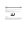
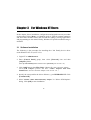
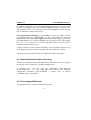
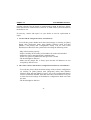
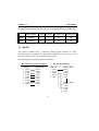
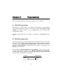
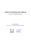
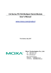
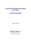
C102
Universal RS-422/485
2 Port Serial Boards
New generation multiport
serial boards family with
state-of-the-art ASIC technology
Sep. 1997 (4th edition)
All Rights Reserved
Copyright Notice
This documentation is copyrighted by Moxa Technologies Co., Ltd. All rights are
reserved. Moxa Technologies reserves the right to make improvements to the products
described in this manual at any time without notice.
Information provided in this manual is intended to be accurate and reliable. However,
Moxa Technologies assumes no responsibility for its use, nor for any infringements of
rights of the fourth party which may result from its use.
MOXA is a registered trademark of Moxa Technologies Co., Ltd.
trademarks in this manual belong to their manufacturers individually.
The other
Moxa Technologies Co., Ltd.
Moxa Tech USA (CA)
Tel:
+866-2-8665-6373
Tel:
(408)734-2224
Fax:
+886-2-8665-6372
Fax:
(408)734-4442
www.moxa.com.tw
support @moxa.com.tw
Moxa Internet Services
Customer’s satisfaction is always our number one concern. To ensure customers get
the full benefit of our services, Moxa Internet Services (MIS) have been built for
technical support, product inquiry, new driver upgrade, etc.
The followings are the services we provide.
E-mail for technical support
address : [email protected]
Ftp site for free driver upgrade
address : ftp.moxa.com or ftp.moxa.com.tw
user ID : ftp
password : your_email_address
World Wide Web (WWW) for product info.
address : www.moxa.com or www.moxa.com.tw
Table of Contents
Chapter 1
1.1
1.2
Chapter 2
2.1
Chapter 3
3.1
3.2
3.3
3.4
3.5
3.6
3.7
Chapter 4
4.1
4.2
4.3
4.4
4.5
Introduction.......................................................................1
Overview ............................................................................1
C102 Family .......................................................................3
Installation.........................................................................7
Hardware Configuration - Io-irq.exe..................................7
For Windows NT Users ......................................................13
Software Installation ........................................................13
Board and Port Configuration ..........................................14
Board Initialization Status Checking ...............................16
Driver Upgrade/Removal .................................................16
Baud Rate Settings ...........................................................17
MOXA Serial Comm Tool: PComm ..................................17
Troubleshooting ...............................................................17
For Windows 95 Users......................................................19
Driver Installation - Setup95.exe .....................................19
Board and Port Configuration ..........................................19
Board Initialization Status Checking ...............................21
Driver Upgrade/Removal .................................................22
Baud Rate Settings ...........................................................22
4.6
MOXA Serial Comm Tool: PComm ..................................22
4.7
Chapter 5
Troubleshooting ...............................................................23
PComm ...............................................................................25
5.1
5.2
5.3
Chapter 6
6.1
6.2
6.3
6.4
6.5
Chapter 7
7.1
7.2
Chapter 8
8.1
8.2
Appendix A
Appendix B
Appendix C
Installation........................................................................25
Programming Library .......................................................25
Utilities .............................................................................26
For DOS Users....................................................................27
Driver Installation, Setup, Loading and Unloading .........27
MOXA Serial Port Naming Convention ..........................30
Baud Rate Settings ...........................................................31
DOS API-232 Library and Programming ........................31
Data Scope........................................................................32
Operations........................................................................33
RS-422..............................................................................34
RS-485..............................................................................35
Programming ...................................................................39
RS-422 Programming.......................................................39
RS-485 programming .......................................................39
Troubleshooting...............................................................43
SCO UNIX/XENIX Standard .................................................47
PC I/O Port Address Map...................................................49
Chapter 1
Introduction
1.1 Overview
The Industrial Multiport Async Solution
The C102 Family, including C102P, C102H, C102HI and C102HIS, supports
2 independent RS-422/RS-485 serial ports. It offers reliable communication link
over a longer distance (4000ft.). It is best suitable for industrial environment.
Connections with point-to-point or multidrop and full-duplex or half-duplex
are available to meet user’s needs.
The C102 Family is equipped with a custom-designed ASIC chip which
replaces lots of conventional ICs and reduces the board to half-size. The whole
family supports 16 bit architecture. Full range of I/O addresses and IRQs are
available. In addition, with on-board EEPROM for storing the configuration
data, the family is designed without jumper or switch. These features make each
port on the board truly independent to any other port and thus compatible with
most existing non-intelligent boards.
Hardware Configuration Method
JP1
Switch
.........
.........
ON
1 2 3 4
ON
1 2 3 4
.........
.........
.........
.........
Jumper
Former C102
C102 Family
1
• Introduction
Chapter 1•
New : set I/O address
Traditional : set switch and
and IRQ via software
and jumper manually for
Utility.
I/O address and IRQ.
Instead of using traditional jumper or switch for IRQ and I/O address settings,
hardware configuration of each port is easily set by DOS utility, Io-irq.exe,
which read and write the on-board EEPROM for configuration information
through the CAP (Configuration Access Port) address. The CAP address is
the only channel via which the configuration utility Io-irq.exe can access the
board, which is identical to the first port's base I/O address.
The only jumper, JP1, is designed in case that users forget the CAP address.
Normally JP1 is left open. When JP1 is short, the CAP address is forced to a
fixed I/O address, 0xA700.
To prevent the boards from damage caused by lighting or high potential voltage,
surge/isolation protection technology is introduced in some models to protect
the board.
Because the family is so flexible in hardware configuration that they are
compatible virtually with all kinds of other manufacturer's non-intelligent
multiport boards using 16450 or 16550 UART.
The family is operational under most popular operating systems such as DOS,
Windows 3.1, Windows NT, Windows 95, SCO UNIX/XENIX/OpenServer,
OS/2, Linux, QNX, FreeBSD, etc. However, MOXA device drivers for DOS,
Windows 95 and Windows NT are provided for better installation,
configuration and performance. In this manual, chapters for MOXA DOS,
Windows 95 and Windows NT device drivers and appendix for SCO
UNIX/XENIX standard driver are included. For other compatible systems not
mentioned, please refer to system’s manual for how to install and configure the
standard driver.
2
Introduction •
• Chapter 1
MOXA Serial Comm Tool
For easy application development, MOXA provides an easy-use serial
communication library under Windows NT/95 (PComm) and Windows
3.x/DOS (API-232). Users can use this library to develop your own
applications using Microsoft C, Turbo C, Assembly, QuickBASIC, Turbo
Pascal, Clipper, Visual Basic, Visual C++, Borland Delphi, etc. Utilities,
such as diagnostic and monitor, are included for diagnosing the
board/port or monitoring the communication status.
It is our commitment to support more operating systems. Please call Moxa
dealer/distributor or visit the MOXA Web site for more information about
newly available device drivers.
1.2 C102 Family
The family consists of members as follows:
C102P
C102H
C102HI
C102HIS
2 port RS-422/RS-485, 16550 UART
2 port RS-422/RS-485, high speed TI550C UART
2 port RS-422/RS-485, isolation protection,TI550C
2 port RS-422/RS-485, isolation + surge protection, TI550C
Features
v
v
v
v
v
Custom-designed ASIC, compact board size (half-size)
No switch no jumper, easily configured by software
Independent I/O address, IRQ setting for each of 2 serial ports
Supports two independent RS-422/RS-485 serial ports
COM1/COM2/COM3/COM4 compatible
3
• Introduction
Chapter 1•
v
v
v
v
v
v
16 bit AT bus architecture, more IRQs supported
High speed TI550C UARTs with on-chip hardware flow control, no data
loss (C102H, C102HI, C102HIS)
Supports DOS/Windows NT/Windows 95 device drivers
2-wire or 4-wire operation
Surge protection (C102HIS)
Opto-isolation (C102HI, C102HIS)
Specifications
v
Bus interface
Number of ports
I/O address
IRQ
Data bits
Stop bits
Parity
UART
:
:
:
:
:
:
:
:
v
Speed (bps)
:
v
Connectors
Data signals
:
:
v
v
v
v
v
v
v
v
v
Surge protection :
Opto-isolation
:
Operating temp. :
Power requirement :
v
Dimensions
v
v
v
:
ISA (EISA compatible)
2
0x0000 ~ 0xFFFF
2, 3, 4, 5, 7, 10, 11, 12, 15
5, 6, 7, 8
1, 1.5, 2
none, even, odd, space, mark
2¡Ñ16550 (C102P)
2¡ÑTI550C (C102H, C102HI, C102HIS)
50 ~ 115.2K (C102P)
50 ~ 921.6K (C102H, C102HI, C102HIS)
2¡ÑDB9 male
TxDB, TxDA, RxDB, RxDA, RTSB, RTSA, CTSB,
CTSA,GND
max. 2000V (C102HIS)
max. 2000V (C102HI, C102HIS)
0 ~ 55¢J
C102P, C102H¡Ð200mA max. (+5V)
C102HI, C102HIS¡Ð750mA max. (+5V)
15.7cm¡Ñ8.3cm (C102P, C102H)
15.7cm¡Ñ10.5cm (C102HI, C102HIS)
4
Introduction •
• Chapter 1
Check List
Upon unpacking the C102 Family, you should find the following items in the
package,
1. C102 Family dual port RS-422/RS-485 board
2. This User's Manual
3. DOS (API-232), Windows NT and Windows 95 device driver diskettes
C102 Family
System Support
The C102 Family is compatible with various operating systems such as SCO
UNIX/XENIX, OS/2, QNX and Linux. In addition, Moxa supports DOS,
Windows NT and Windows 95 device drivers for C102 Family for better
installation, configuration and performance. See the driver list below.
5
• Introduction
Chapter 1•
C102 Family
3
C
3
3
C
C
C
C
C
C
DOS
Windows 3.1
Windows NT
Windows 95
Linux
QNX
SCO UNIX/OpenServer
SCO XENIX
OS/2
FreeBSD
3: Driver supported by Moxa and shipped with product
R : Driver supported by Moxa but shipped by request
C : Driver supported by OS
Note: MOXA FTP site is available for driver download.
6
Chapter 2
Installation
The installation of C102 Family is as follows:
1. Start with hardware configuration. See next Section for Io-irq.exe.
2. Continue with the software (driver) installation according to the
corresponding operating system chapters for details.
In this manual, chapters for MOXA DOS, Windows 95 and Windows NT
device drivers are included. For other compatible systems not mentioned,
please refer to system’s manual for how to install and configure the standard
driver.
Remember to keep the hardware settings in mind for the software
installation.
After this, users already complete the whole installation.
2.1 Hardware Configuration - Io-irq.exe
Because the ASIC-designed C102 Family has no switch no jumper, users must
configure the I/O address, IRQ, INT Vector, etc. of the boards via utility, Ioirq.exe, before proceeding to install. To set up the hardware configuration for
C102 Family, please run Io-irq.exe in the driver diskette under DOS system.
1. Choose a PC that has DOS system inside.
2. Power off the PC.
7
Chapter 2 l
l
Installation
3. Make sure no hardware conflict and plug the board in a free 16-bit slot of the
PC, one board at a time with JP1 open.
+
If you are installing multiple boards, insert one board at a time and
configure it using the Io-irq program before inserting the next board.
This is to prevent conflict between two boards with same default
hardware settings.
The C102 Family has the following default (factory) settings,
I/O address : 0x180 (1st port), 0x188 (2nd port)
IRQ : 10 (shared by 4/8 ports)
INT Vector : 0x1C0
Configuration Access Port (CAP) : 0x180
4. Power on the PC and enter into DOS system.
5. Run the utility "Io-irq.exe" contained in the driver diskette to set up I/O
address, IRQ and INT vector of the board. Follow the on-line help to
configure the C102 Family board.
After completing the hardware configuration, the board is ready for use
under operating systems such as Windows NT/95, SCO UNIX, DOS, etc.
Note that the CAP address, e.g. 0x180, is identical to the first port's I/O
address except in one case that the JP1 jumper is installed before powering
on the PC. In this case, the CAP address will be forced to 0xA700. The CAP
address must be typed correctly. With the correct CAP address, the utility
can find the configuration stored in the on-board EEPROM and display it
on the configuration panel. The CAP address is the only channel via which
the configuration utility Io-irq.exe can access the board.
8
Installation l
l
Chapter 2
The followings are fields for configuration:
Port Index: Indicate the port index for each port.
I/O address: Enter the base I/O address for each port, either sequentially or not.
Avoid to conflicting with any other devices.
Speed: This field specify the use of normal or high speed capability. Normal
speed ranges from 50 bps to 115.2 Kbps. High speed ranges from 50 bps to
921.6 Kbps. C102 H Series supported both normal and High Speed Spectra,
such as C102H, C102HS, and C102HIS. For C102 non H Series, only Normal
Speed Spectrum is supported. In other word, to use speed faster than 115.2
Kbps, e.g. 460.8 Kbps, C102 H Series set to High Speed Spectrum is required.
Note that, currently, port that uses MOXA Windows 95 and Windows NT
driver will run at the displayed speed. To be clear, when C102 H Series board
is configured as High Speed Spectrum, any port driven by the Moxa-provided
Windows 95/NT driver will display the exact working speed. For example, the
displayed speed 38.4 Kbps is equal to the working speed 38.4 Kbps.
However, if the port is driven by non Moxa-provided driver, such as standard
serial driver, or Moxa drivers other than Windows 95/NT, such as DOS, the
real working speed is equal to 8 times of the displayed speed. For example, a
port, if set to Normal Speed Spectrum with 38.4 Kbps, will work at 38.4 Kbps
for sure; while a port, if set to High Speed Spectrum with displayed speed 38.4
Kbps, will actually work at 307.2 Kbps (38.4 Kbps¡Ñ8).
9
Chapter 2 l
l
Installation
The following is the 8 times speed mapping list for quick reference purpose.
Normal Speed Spectrum
High Speed Spectrum
50
(bps)
75
110
134.5
150
300
600
1200
1800
2400
4800
7200
9600
19.2K
38.4K
57.6K
115.2K
400
(bps)
600
880
1076
1200
2400
4800
9600
14.4K
19.2K
38.4K
57.6K
76.8K
153.6K
307.2K
460.8K
921.6K
IRQ: Enter the IRQ, 2, 3, 4, 5, 7, 10, 11, 12 or 15, for each port,
independently or not.
Interrupt Vector: Enter the interrupt vector I/O address for all ports. I/O
address for interrupt vector is from 00000H to 0FFFFH. Interrupt vector is
one byte of I/O address, in which each bit is used to indicate the occurrence
of interrupt for corresponding port. To use interrupt vector, type in the
hardware Interrupt vector I/O address. If not using interrupt vector, type 0 or
leave blank as the interrupt vector.
There are two modes for the C102 driver. One is using interrupt vector, the
10
Installation l
l
Chapter 2
other is not using interrupt vector. Driver employing interrupt vector scheme is
supposed to have better performance than employing polling scheme.
Tx enable: To control the enable/disable mode of the driver, there are 3 options:
"Always On", "By Register" and "By RTS" for the driver. The setting should
be correlated with setting of receiver. See later description for details.
Rx enable: To control the enable/disable mode of the receiver, there are 2
options: "Always On", "By Register" and "By /RTS" for the receiver.
For RS-422 communications, set [Tx, Rx] to [Always On, Always On] and use
point-to-point full-duplex operation. See Chapter 6 "Operations" for details.
For RS-485 communications, there are several setting combinations for Tx and
Rx: (See Chapter 6 "Operations" for details.)
1. Point-to-point full-duplex operation
Set [Tx, Rx] to [Always On, Always On].
2. Point-to-point half-duplex operation
For echo mode , set [Tx, Rx] to [By Register, Always On] or [By RTS,
Always On]. For non-echo mode, set [Tx, Rx] to [By Register, By Register]
or [By RTS, By /RTS].
3. Multidrop full-duplex operation
Set [Tx, Rx] of the master to [Always On, Always On]. Set [Tx, Rx] of the
slaves to [By Register, Always On] or [By RTS, Always On].
4. Multidrop half-duplex operation
For echo mode, set [Tx, Rx] of the master and slaves to [By Register,
Always On] or [By RTS, Always On]. For non-echo mode, set [Tx, Rx] to
[By Register, By Register] or [By RTS, By /RTS].
11
Chapter 3 For Windows NT Users
In this chapter, driver installation, configuration and upgrade/removal procedure
are described. Utility, Mxtty, is explained, which is good for terminal emulation
and file transfer. Related issues such as baud rate settings, existing applications
and programming are also stated. Finally, Windows NT-specific troubleshooting is
included.
3.1 Software Installation
The following is the procedure for installing the C102 Family device driver
under Windows NT 4.0 (or NT 3.51):
1. Login NT as Administrator.
2. Enter [Control Panel] group, then select [Network] icon and then
[Adapters] folder.
(Enter [Control Panel] folder and then select [Network] icon for NT 3.51.)
3. Click [Add] button, then [Have Disk...] button for "Select Network Adapter".
(Click [Add Adapter...] button and then "<Other> Requires disk from
manufacturer" item for "Network Adapter Card:" for NT 3.51.)
4. Specify the exact path for the driver diskette, e.g. A:\WINDOWS.NT. Click
[Continue/OK].
5. Select "MOXA C102/C104/C168 Family Adapter" in "Select OEM Option"
dialog. Click [OK] to start installation.
12
For Windows NT Users l
l
Chapter 3
6. When MOXA C102/C104/C168 Configuration Panel is popped up, to
configure the board(s) and ports, please refer to the Section "Board and
Port Configuration" for more details.
7. Select [OK] for "Network Settings" dialog. Restart system as prompted.
3.2 Board and Port Configuration
The following is the procedure for configuring the C102 Family driver under
Windows NT 4.0 (or NT 3.51):
1. Enter [Control Panel] group, then select [Network] icon and then
[Adapters] folder.
(Enter [Control Panel] folder and then select [Network] icon for NT 3.51.)
2. Select "MOXA C102/C104/C168 Adapter" item for "Installed Adapter
Cards:", then [Configure/Properties] button to start the "MOXA
C102/C104/C168 Family Configuration Panel" dialog.
When the configuration panel is popped up:
Click [Add] button to add a board.
Click [Remove] button to remove a board.
Click [Properties] button to set up a board with correct "Board Type",
"IRQ", "INT Vector", "I/O Address", "COM Number" and "Received FIFO
Trigger Level", where the possible parameters are as follows:
Board Type: C102 Family.
13
Chapter 3 l
l
For Windows NT Users
IRQ No.: 2, 3, 4, 5, 7, 10, 11, 12, 15
INT Vector: I/O address for interrupt vector from 00000H to 0FFFFH. To
use INT vector, type in the hardware INT vector I/O address. If not using
INT vector, type 0 or leave blank as the INT vector.
There are two modes for the C102 driver. One is using INT vector, the other
is not using INT vector. INT vector is one byte of I/O address, in which each
bit is used to indicate the occurrence of interrupt for corresponding port.
Driver employing INT vector scheme is supposed to have better performance
than employing polling scheme.
Sequential Port Mapping: For I/O Address, specify the I/O address of the
first port and subsequent ports are set to continuous I/O addresses by the
offset of 8 bytes. For instance, if the first port is set to 0x180, then the
second port is set to 0x188 sequentially. For COM number, specify the COM
number of the first port and subsequent ports are mapped to continuous
COM numbers. For instance, if the first port is mapped to COM10, then the
second port is mapped to COM11 sequentially. For receive FIFO trigger level
(bytes), every port will have the same trigger level as set. For 16550compatible type of UART, receive FIFO trigger level is 1, 4, 8 or 14 bytes.
For 16450-compatible UART, only one byte is available no matter what you
set.
Non-sequential Port Mapping: For I/O Address, set the I/O address of each
port independently. For COM number, set the COM number of each port
independently. For receive FIFO trigger level (bytes), set the trigger level of
each port independently. For 16550-compatible type of UART, receive FIFO
trigger level is 1, 4, 8 or 14 bytes. For 16450-compatible UART, only one
byte is available no matter what you set.
At most 4 boards of C102/C104/C168 Family can be installed together as
long as the IRQ and I/O address resources are sufficient and available in a
14
For Windows NT Users l
l
Chapter 3
system.
3. Unless the system restarted, the latest configuration will not take effect.
3.3 Board Initialization Status Checking
There are two alternative ways to find out if ports of the board are initialized
successfully:
1. Enter [Control Panel] group and then [Ports] icon, to check the port list and
see if all configured ports are already added in the system correctly.
If no configured port shown in the port list, refer to Section
"Troubleshooting" for solutions.
2. Enter [Administrative] group, then [Event Viewer] icon and then [System
Event Log] to check for message like " COM3 (C102 port 1) O.K." for each
configured port.
If message is "Can not find the configured C102/C104/C168
(CAP=0xXXXX) !", refer to Section "Troubleshooting" for solutions.
3.4 Driver Upgrade/Removal
To upgrade driver, remove the installed driver first and install the new one.
To remove driver,
1. Enter [Control Panel] group, then select [Network] icon and then
[Adapters] folder.
(Enter [Control Panel] folder and then select [Network] icon for NT 3.51.)
15
Chapter 3 l
l
For Windows NT Users
2. Select "MOXA C102/C104/C168 Adapter" in adapter list and then
[Remove] button to start removing the MOXA board.
3.5 Baud Rate Settings
When C102 H Series board is configured as High Speed Spectrum, any port
driven by the Moxa-provided driver will display the exact working speed. For
example, the displayed speed 38.4 Kbps is equal to the working speed 38.4
Kbps.
However, if the port is driven by non Moxa-provided driver, such as
standard serial driver, the real working speed is equal to 8 times of the
displayed speed. For example, a port, if set to Normal Speed Spectrum with
38.4 Kbps, will work at 38.4 Kbps for sure; while a port, if set to High Speed
Spectrum with displayed speed 38.4 Kbps, will actually work at 307.2 Kbps
(38.4 Kbps¡Ñ8).
3.6 MOXA Serial Comm Tool: PComm
PComm is a software package consisting of MOXA serial communication
library and utilities for diagnostic and monitor as well as example
programs under Windows NT/95. Please see Chapter "PComm" for details.
3.7 Troubleshooting
The error messages and solutions are stated as clearly as possible. If all the
possible solutions fail, the board or connection box might be defective. Please
check the board or connection box ONE AT A TIME in the system and find out
16
For Windows NT Users l
l
Chapter 3
the defective one.
If necessary, contact and report it to your dealer at once for replacement or
repair.
1. Can not find the configured C102 (CAP=0xXXXX) !
To avoid this, please double check the board settings from the driver
configuration for each board installed, then shut down the system before
checking the following items:
- Plug in the board(s) properly.
- Inspect carefully on the settings of I/O address for each board installed.
- Sometimes slot for plugging board is malfunctional.
In this case, please try other slots until good one is found.
- The board might be defective.
- Make sure the jumper JP1 is always open and the I/O addresses are not
occupied by other devices.
2. The C102's software and hardware configuration mismatch (CAP=0xXXXX) !
- To avoid this, please check the board settings of the software configuration
via entering [Control Panel] group, then [Network] icon, then [Adapters]
folder and then [MOXA C102/C104/C168 Configuration Panel] icon for
each board installed, then shut down the system and run Io-irq.exe to check
the board settings of the hardware configuration. Make sure both are same.
- The board might be defective.
17
Chapter 4 For Windows 95 Users
In this chapter, driver installation, configuration and upgrade/removal procedure
are described. Utility, Mxtty, is explained, which is good for terminal emulation
and file transfer. Related issues such as baud rate settings, existing applications
and programming are also stated. Finally, Windows 95-specific troubleshooting
is included.
4.1 Driver Installation - Setup95.exe
1. Run Setup95.exe in the driver diskette.
2. Select "MOXA C102/C104/C168 Family Driver" to install the driver.
3. When "MOXA C102_C104_C168 Configuration Panel" is popped up, to
configure the board(s) and ports, please refer to the Section "Board and
Port Configuration" for more details.
After this, users already complete the whole installation.
4. Restart Windows 95.
5. Check the board initialization status after logging in the system. Refer to
Section "Board Initialization Status Check" for details.
4.2 Board and Port Configuration
You will enter the configuration program when installing the driver. Or you can
18
For Windows 95 Users l
l
Chapter 4
click on the Taskbar [Start] button, then select [Programs] menu, then [MOXA
Utilities] menu and then [MOXA C102_C104_C168 Configuration Panel] icon.
When the configuration panel is popped up:
Click [Add] button to add a board.
Click [Remove] button to remove a board.
Click [Properties] button to set up a board with correct "Board Type", "IRQ",
"INT Vector", "I/O Address", "COM Number" and "Received FIFO Trigger
Level", where the possible parameters are as follows:
Board Type: C102 Family.
IRQ: 2, 3, 4, 5, 7, 10, 11, 12, 15.
INT Vector: I/O address for interrupt vector from 00000H to 0FFFFH. To use
INT vector, type in the hardware INT vector I/O address. If not using INT
vector, type 0 or leave blank as the INT vector.
There are two modes for the C102 driver. One is using INT vector, the other is
not using INT vector. INT vector is one byte of I/O address, in which each bit is
used to indicate the occurrence of interrupt for corresponding port. Driver
employing INT vector scheme is supposed to have better performance than
employing polling scheme.
Sequential Port Mapping: For I/O Address, specify the I/O address of the first
port and subsequent ports are set to continuous I/O addresses by the offset of 8
bytes. For instance, if the first port is set to 0x180, then the second port is set to
0x188 sequentially. For COM number, specify the COM number of the first
port and subsequent ports are mapped to continuous COM numbers. For
instance, if the first port is mapped to COM10, then the second port is mapped
19
Chapter 4 l
l
For Windows 95 Users
to COM11 sequentially. For receive FIFO trigger level (bytes), every port will
have the same trigger level as set. For 16550-compatible type of UART, receive
FIFO trigger level is 1, 4, 8 or 14 bytes. For 16450-compatible UART, only one
byte is available no matter what you set.
Non-sequential Port Mapping: For I/O Address, set the I/O address of each
port independently. For COM number, set the COM number of each port
independently. For receive FIFO trigger level (bytes), set the trigger level of each
port independently. For 16550-compatible type of UART, receive FIFO trigger
level is 1, 4, 8 or 14 bytes. For 16450-compatible UART, only one byte is
available no matter what you set.
At most 4 boards of C102/C104/C168 Family can be installed together as long
as the IRQ and I/O port resources are sufficient and available in a system.
Unless the system restarted, the latest configuration will not take effect.
4.3 Board Initialization Status Checking
All the error conditions, during the initialization of Windows 95, will be popped
up onto the screen. Otherwise, everything should be fine.
If message like "Can not find the configured C102/C104/C168
(CAP=0xXXXX) !" or "The C102/C104/C168's software and hardware
configuration mismatch (CAP=0xXXXX) !" shows, refer to Section
"Troubleshooting " for solutions.
4.4 Driver Upgrade/Removal
To upgrade the driver, simply install the driver again.
20
For Windows 95 Users l
l
Chapter 4
To remove driver, just remove all the configured boards. Once the MOXA
driver is installed, it exists permanently in Windows 95 like other adapters do.
Removing changes nothing but that particular board's existence in Windows 95
Registry.
4.5 Baud Rate Settings
When C102 H Series board is configured as High Speed Spectrum, any port
driven by the Moxa-provided driver will display the exact working speed. For
example, the displayed speed 38.4 Kbps is equal to the working speed 38.4
Kbps.
However, if the port is driven by non Moxa-provided driver, such as
standard serial driver, the real working speed is equal to 8 times of the
displayed speed. For example, a port, if set to Normal Speed Spectrum with
38.4 Kbps, will work at 38.4 Kbps for sure; while a port, if set to High Speed
Spectrum with displayed speed 38.4 Kbps, will actually work at 307.2 Kbps
(38.4 Kbps¡Ñ8).
4.6 MOXA Serial Comm Tool: PComm
PComm is a software package consisting of MOXA serial communication
library and utilities for diagnostic and monitor as well as example
programs under Windows NT/95. Please see Chapter "PComm" for details.
4.7 Troubleshooting
The error messages and solutions are stated as clearly as possible. If all the
21
Chapter 4 l
l
For Windows 95 Users
possible solutions fail, the board or connection box might be defective. Please
check the board or connection box ONE AT A TIME in the system and find out
the defective one.
If necessary, contact and report it to your dealer at once for replacement or
repair.
1. Can not find the configured C102 (CAP=0xXXXX) !
To avoid this, please double check the board settings via clicking on [Start]
button, then [Programs] menu, then [MOXA Utilities] menu and then
[MOXA C102_C104_C168 Configuration Panel] icon for each board
installed, then shut down the system before checking the following items:
- Plug in the board(s) properly.
- Inspect carefully on the setting of I/O address for each board installed.
- Sometimes slot for plugging board is malfunctional.
In this case, please try other slots until good one is found.
- The board might be defective.
- Make sure the jumper JP1 is always open and the I/O addresses are not
occupied by other devices.
2. The C102's software and hardware configuration mismatch (CAP=0xXXXX) !
- To avoid this, please check the board settings of the software configuration
via clicking on [Start] button, then [Programs] menu, then [MOXA
Utilities] menu and then [MOXA C102_C104_C168 Configuration Panel]
icon for each board installed, then shut down the system and run Io-irq.exe
to check the board settings of the hardware configuration. Make sure both
are same.
- The board might be defective.
22
Chapter 5
PComm
PComm, the professional serial comm tool for PC, is a software package
under Windows NT/95, which consists of powerful serial communication
library for easy programming in most popular languages, useful utilities
such as diagnostic and monitor, illustrative example programs and
comprehensive on-line documents.
The serial communication library is especially for users who develop a
system for data communication, remote access, data acquisition or
industrial control in the Windows NT/95 environment, which offers an
easier solution compared with the more complex Windows Win32
COMM API.
5.1 Installation
To install PComm, please run \Setup.exe in the diskette.
Note that the MOXA Windows NT/95 device driver is required as
using PComm diagnostic and monitor utilities.
5.2 Programming Library
The serial communication library is to assist users to develop
programs for serial communications for any COM port complying
23
Chapter 5 l
l
PComm
with Microsoft Win32 API. It can ease the implementation of multiprocess and multi-thread serial communication programs and hence
greatly reduce the developing time.
For complete library function description and example programs for
Visual C++, Visual Basic and Delphi, please see help file and example
programs in PComm directory for more details.
5.3 Utilities
The followings are short descriptions of each utility. For details,
please see on-line help in the diskette.
Diagnostic
A convenient diagnostic program provides internal and external
testing, such as IRQ, TxD/RxD, UART, CTS/RTS, DTR/DSR,
DTR/DCD testing, etc., for the MOXA boards and ports to verify
correct operation of both the software and hardware.
Monitor
A useful port status monitoring program allows users to watch the
selected MOXA COM ports’ data transmitting/receiving throughput
and communication line status which are updated and displayed on the
screen at every time interval. In addition, users may click on one of
the specific displayed port in order to see the current communication
parameters and status of that port.
24
Chapter 6
For DOS Users
The C102 is useful for industrial control as well as data acquisition and
communication. Because many users need to implement an industrial control
system or data acquisition system in the DOS environment, but DOS did not
have any better communication API, thus Moxa has developed device drivers
and library functions under DOS. Furthermore, Data Scope utility is very
helpful for troubleshooting and debugging the serial communications.
In this chapter, driver installation, setup, loading and removal procedure are
described. Utility, Data Scope, is explained, which is good for terminal
emulation, data scope and diagnostics. Related issues such as device naming,
baud rate settings and programming are also stated.
6.1 Driver Installation, Setup, Loading and Unloading
MOXA DOS API-232 is a software package that assists users to develop and/or
debug programs for serial communications. It supports device drivers for the
MOXA boards such as C102/C104/C168 Family, C218/C320 Series, standard
PC COM ports, etc.
Driver Installation
Run the installation program, DOSINST.EXE, in the API-232 software diskette.
Specify the target API-232 directory (e.g. C:\MOXA) where software driver
and library will be copied to. Press F2 to start the installation.
25
Chapter 6 l
l For
DOS Users
Driver Setup
1. Change to API-232 directory and run the setup program, BIN\SETUP.EXE.
This program is to configure IRQ, port number, etc., of the MOXA boards.
The configuration will be referred to by the later executed DOS driver. Note
that before running SETUP program, execute Io-irq to designate I/O
address and IRQ.
2. Choose "C102/C104/C168 Series Multiport Board" in the "DRIVER
SELECTION" dialog and then enter or modify each port's configuration
which are the port initial value when driver is loaded.
3. Use F8 function to load the on-board configuration for C102 Family. Use
other functions to modify settings if necessary. Finally remember to use F10
function to save the configuration.
Some noticeable functions keys and fields are explained below.
Press F1: "Help" to learn an up-to-date instructions.
Press F3: "Add port" to add one port entry and modify the settings if
necessary.
Press F4: "Delete port" to delete the port entry where the cursor stops.
Press F5: "Group edit" to set the selected ports (as a group) to the same
settings.
Press F6: "INT vector" to specify the interrupt vector I/O address and set
the status for each port. Interrupt-driven scheme is applied for
those ports using interrupt vector while polling scheme for those
ports not using interrupt vector. The former is more efficient and
26
For DOS Users l
l Chapter
6
has better performance in terms of driver.
Press F8: "Load config" to load the hardware configuration stored in the
on-board EEPROM at CAP address. This is the most convenient
way of C102/C104/C168 Family configuration, comparing to add
port one by one with function F3.
Port number
:
This is actually the port ID of each port. The application
software will refer to the port by its port number (ID).
Duplicated port number is not allowed.
Base I/O address :
The I/O address of each port. Overlapped or duplicated
I/O address is not allowed.
Interrupt number :
The IRQ number of each port. Several ports may share
one common IRQ.
TxD buffer size
:
The transmit (output) buffer reserved for the port.
RxD buffer size
:
The receive (input) buffer reserved for the port.
Driver Loading
Having completed the setup, load the TSR driver, BIN\SER-DRV.EXE, at the
DOS prompt. The driver will detect the multiport board automatically. If the
board(s) is(are) detected, a message similar to below will show:
Universal 2/4/8 Serial Port Communication Driver (Ver x.x)
Device Driver Setup O.K.
Which means the board and the driver have been successfully installed. At this
point, user is ready to execute application that supports API-232 functions, or
27
Chapter 6 l
l For
DOS Users
start developing applications.
If there is no matched port, the screen will show a message like:
Universal 2/4/8 Serial Port Communication Driver (Ver x.x)
No Serial Port Found!!
Please refer to Appendix A Troubleshooting for possible reasons and solutions.
To support various types of UARTs such as 16450, 16550 and TI550C, several
options for SER-DRV are provided. Type SER-DRV/? to see the available
options.
Driver Unloading
To remove the driver from memory, type SER-DRV/Q at the DOS prompt.
6.2 MOXA Serial Port Naming Convention
Each MOXA serial port are referenced as port number in terms of programming.
The port numbers are automatically assigned once the starting port number is
decided by user when configuring the ports of the board. Duplication of the port
numbers is not allowed.
For example, if 2 ports are configured and the starting port number is 1, then the
mapping of serial port numbers will be as depicted.
28
For DOS Users l
l Chapter
6
1
2
C102 Family
6.3 Baud Rate Settings
Be aware that, for those C102 H Series boards configured as High Speed
Spectrum, the real working speed is equal to 8 times of the displayed speed.
For example, a port, if set to Normal Speed Spectrum with 38.4 Kbps, will work
at 38.4 Kbps for sure; while a port, if set to High Speed Spectrum with shown
speed 38.4 Kbps, will actually work at 307.2 Kbps (38.4 Kbps¡Ñ8). This is
applicable to Moxa-provided driver and utility, such as Setup and Data Scope,
and also any non Moxa-provided driver and utility, such as Telix.
6.4 DOS API-232 Library and Programming
For DOS programming, API-232 includes powerful libraries supporting
languages like Microsoft C, Turbo C, Macro Assembly, QuickBasic, Turbo
Pascal, Clipper, etc. Sample programs for each supported language are included,
and placed in the sub-directory ..\EXAMPLE\language of the API-232
directory.
In addition, for DOS C language only, there are also Modem Control and File
Transfer library available, supporting Hayes compatible modem control as well
as ASCII, KERMIT, XMODEM, YMODEM and ZMODEM file transfer
protocol functions.
29
Chapter 6 l
l For
DOS Users
For complete and last-minute API-232 function description, see file API-232.TXT
in the API-232 directory for more details.
6.5 Data Scope
The Data Scope, BIN\SCOPE.EXE, is a suite of utility programs that can help
users with system troubleshooting and serial communication debugging. There
are three major functions:
1. The Data Scope utility offers transparent monitoring of serial communication
lines and allows data to be streamed to disk storage for later analysis.
2. The TTY terminal emulation utility allows user to view the signal status and
transfer data interactively or files using ASCII, XMODEM, YMODEM,
ZMODEM and KERMIT protocols.
3. The diagnostic test utility provides port connection test with two MOXA
ports connected via a properly-wired cable.
Please see on-line help as running BIN\SCOPE.EXE for more usage and capability
information.
30
Chapter 7
Operations
The C102 Family is particularly designed for RS-422/485 communications. For
RS-422 communications, there is two types of operation, point-to-point fullduplex and broadcasting. However, for RS-485 communications, there are
various operations for various applications. To be able to make the desired RS422/RS-485 operation work, there are four things to do:
1. Correctly install and configure the C102 board. See Chapter 2 "Installation"
for details.
2. Correctly configure the driver. See Chapter 3~5 for details.
3. Correct cable wiring. See Chapter 6 "Operations" for details.
4. Correct programming. See Chapter 7 "Programming" for details.
The C102 has two DB-9 male connectors. Their pin assignments are:
Pin no.
Signal
1
2
3
4
5
6
7
8
9
TxDA
TxDB
RxDB
RxDA
GND
RTSA
RTSB
CTSB
CTSA
31
Chapter 7 l
l
Operations
The following comparison table is for EIA Standards RS-422 and RS-485.
Mode of operation No. of Drv. No. of Rcv. Max. length ( FT ) Max. Rate ( bps )
RS-422
differential
1
10
4000
10M
RS-485
differential
32
32
4000
10M
7.1 RS-422
The RS-422 standard uses a balanced voltage digital interface to allow
communications of 10 Mbps on cable length of 4000 feet. Ten receivers can be
connected to any one driver for broadcasting systems.
The followings are operation modes for RS-422:
RS-422 Point-to-point full-duplex
C102 site
1 TxDA
2 TxDB
3 RxDB
4 RxDA
5 GND
6 RTSA
7 RTSB
8 CTSB
9 CTSA
Remote site
RxDA
RxDB
TxDB
TxDA
GND
CTSA
CTSB
RTSB
RTSA
RS-422 Broadcasting
C102 Site
1 TxDA
4 RxDA
2 TxDB
3 RxDB
5 GND
Remote Site 1
RxDA
TxDA
RxDB
TxDB
GND
Remote site n
RxDA
TxDA
RxDB
TxDB
GND
32
Operations l
l
Chapter 7
For RS-422 communications, do set [Tx, Rx] port features in the Io-irq
hardware configuration utility to [Always On, Always On] and then use pointto-point full-duplex or broadcasting operation. See Chapter 2 "Installation"
Section 2.1 "Hardware Configuration - Io-irq.exe" for details.
7.2 RS-485
The RS-485 standard is an enhanced version of the RS-422A balanced line
standard. It allows multiple drivers and receivers in a multidrop systems. As
many as 32 drivers and 32 receivers can be put on any multidrop system.
There are basically two operations for RS-485, point-to-point and multidrop.
And each operation has half and full-duplex options. For half-duplex, there are
still echo and non-echo modes. Since TxDB and RxDB are wired together (see
pictures below), whatever data sent from TxDB will be received by RxDB of
the local site and, of course, the RxDB of the other site. If the local RxDB is
enabled to receive data, it is called echo mode. Otherwise, the local RxDB is
disabled and it is called non-echo mode. If the port feature is set to [By RTS,
By /RTS], only the non-echo mode is possible. See Chapter 7 "Programming"
Section 7.2 "RS-485 Programming" for details.
Point-to-point
Point-to-point communications means two devices located at two different
places can be linked together to communicate via RS-485 interface. Depending
on the wiring, half-duplex or full-duplex can be used.
33
Chapter 7 l
l
Point-to-point RS-485 Half-duplex
C102 site
1 TxDA
4 RxDA
2 TxDB
3 RxDB
5 GND
Operations
Point-to-point RS-485 Full-duplex
Remote site
TxDA
RxDA
TxDB
RxDB
GND
C102 site
1 TxDA
4 RxDA
2 TxDB
3 RxDB
5 GND
Remote site
RxDA
TxDA
RxDB
TxDB
GND
In accordance with the point-to-point operation shown above, there are a couple
of setting combinations for Tx and Rx:
1. Point-to-point full-duplex operation
Set [Tx, Rx] to [Always On, Always On].
2. Point-to-point half-duplex operation
For echo mode, set [Tx, Rx] to [By Register, Always On] or [By RTS,
Always On]. For non-echo mode, set [Tx, Rx] to [By Register, By Register]
or [By RTS, By /RTS].
Multidrop
Multidrop communication means that more than two devices can be linked
together to communicate with one another via RS-485 interface. In this
operation, one of the device serves as master device while the rest of the
devices as slaves. Normally, master will send data to individual slave and the
slave will receive the data according to its ID (or any site-specific identification)
embedded in the data. This is how master communicate with each slave.
However, broadcasting is also possible if the master sends data without any ID
to all the salves.
34
Operations l
l
Chapter 7
Depending on the wiring, half-duplex or full-duplex can be used.
Multidrop RS-485 Half-duplex
Multidrop RS-485 Full-duplex
C102 site
Master
Remote site 1
Slave
C102 site
Master
Remote site 1
Slave
1 TxDA
4 RxDA
2 TxDB
3 RxDB
5 GND
TxDA
RxDA
TxDB
RxDB
GND
1 TxDA
4 RxDA
2 TxDB
3 RxDB
5 GND
RxDA
TxDA
RxDB
TxDB
GND
Remote site n
Slave
Remote site n
Slave
TxDA
RxDA
TxDB
RxDB
GND
RxDA
TxDA
RxDB
TxDB
GND
In accordance with the multidrop operations shown above, there are a couple of
setting combinations for Tx and Rx:
1. Multidrop full-duplex operation
Set [Tx, Rx] of the master to [Always On, Always On]. Set [Tx, Rx] of the
slaves to [By Register, Always On] or [By RTS, Always On].
2. Multidrop half-duplex operation
For echo mode, set [Tx, Rx] of the master and slaves to [By Register,
Always On] or [By RTS, Always On]. For non-echo mode, set [Tx, Rx] to
[By Register, By Register] or [By RTS, By /RTS].
35
Chapter 7 l
l
36
Operations
Chapter 8
Programming
The C102 Family boards could be used as either RS-422 or RS-485.
8.1 RS-422 Programming
When RS-422 is needed, there is no difference from RS-232 in programming
except that the cable wiring must refer to RS-422's and the [Tx enable] and [Rx
enable] port features must be set to "Always On" in the Io-irq board
configuration software.
For cable wiring, please refer to Chapter 6 "Operations" for RS-422 operation
details.
8.2 RS-485 programming
The C102 Family has two independent ports and each port has one receiver (Rx)
and one driver (Tx). Both driver and receiver can be either enabled or disabled
in order to achieve point-to-point half/full-duplex communication but also the
multidrop half/full-duplex communication. See Chapter 6 "Operations" for
RS-485 operation details.
The principle for RS-485 full-duplex programming is same as that for RS232/422 programming. However, for RS-485 half-duplex programming,
remember that only one signal line can be enabled when Tx and Rx of both sites
are physically wired together. For example,
C102 site
Remote site
TxDA
RxDA
TxDA
RxDA
37
Chapter 8 l
l
Programming
When the TxDA of C102 site is enabled to transmit data, the TxDA of the
remote site should be disabled and RxDA of remote site should be enabled to
receive data. Meanwhile, the RxDA of the C102 site can be either enabled to
receive data from TxDA of C102 site, which is call echo mode, or disabled,
which is called non-echo mode.
In a half-duplex environment, contention problems (or data collision) will
occur if two devices attempt to transmit data simultaneously. For example, if the
TxDA of both the C102 site and the remote site are enabled at the same time,
the data sent will be garbled due to the contention problems. However, if the
TxDA of both the C102 site and the remote site are disabled, the line will be
floating.
To control the enable/disable mode of the driver and receiver, there are 3
options: "Always On", "By Register" and "By RTS" for the driver (Tx enable
feature in Io-irq) and 3 options: "Always On", "By Register" and "By /RTS"
for the receiver (Rx enable feature in Io-irq) to be chosen in the Io-irq board
configuration software.
1.
Always On
If the [Tx enable] and [Rx enable] port features are set to "Always On" in
the Io-irq board configuration software, the driver/receiver is always
enabled and ready for transmitting/receiving data.
2.
By Register
If the [Tx enable] or [Rx enable] port feature is set to "By Register" in the
Io-irq board configuration software, the driver (or receiver) is controlled by
bit 1 (or bit 0) of the control register BASE + 7, where BASE is the base
I/O address of the UART for the port. When the corresponding bit is set to
"1", the driver/receiver is enabled. Setting the corresponding bit to "0" will
turn the driver/receiver off and the 16x50 UART chip will not
transmit/receive any signal. That is, driver and receiver are controlled
independently.
"By Register" is only suitable for any system that allows register control,
38
Programming l
l
Chapter 8
i.e. direct I/O access, from application programs, such as DOS. For
example, in Turbo C language under DOS system, a statement as following
will turn on the driver:
outportb(BASE + 7, 1);
/* turn on driver and turn receiver off */
A statement as following will turn on the receiver:
outportb(BASE + 7, 2);
/* turn on receiver and turn off driver */
A statement as following will turn off both the driver and receiver:
outportb(BASE + 7, 0);
/* turn off both driver and receiver
*/
A statement as following will turn on both the driver and the receiver:
outportb(BASE + 7, 3);
/* turn on both driver and receiver
*/
For systems where direct access of the I/O address is not allowed, such as
Windows 95 and Windows NT, "By RTS" or "By /RTS" is recommended,
instead.
3.
By RTS or By /RTS
The [Tx enable] (or [Rx enable]) port feature can be set to "By RTS" (or
"By /RTS") in the Io-irq board configuration software. The driver and
receiver are controlled independently.
The driver is enabled, if driver is set to "By RTS" and the RTS signal is on.
The driver is disabled, if driver is set to "By RTS" and the RTS signal is
off.
If receiver is set to "By /RTS" and the RTS signal is on, the receiver is
disabled. If receiver is set to "By /RTS" and the RTS signal is off, the
receiver is enabled.
"By RTS" or "By /RTS" is suitable for any system that allows RTS control
from application programs. Any one of the statements as following will set
39
Chapter 8 l
l
Programming
RTS signal true and turn on the driver or turn off the receiver:
sio_RTS(port, 1);
or
sio_putb_x();
or
outportb(BASE + 4, 2);
/* turn on RTS */
/* turn on RTS before data sent */
/* turn on RTS, direct I/O access.
Where BASE is the base I/O address of
the UART of the port */
Any one of the statements as following will clear the RTS signal and turn
off the driver or turn on the receiver:
sio_RTS(port, 0);
or
sio_putb_x();
or
outportb(BASE + 4, 0);
/* turn off RTS */
/* turn off RTS after data sent */
/* turn off RTS, direct I/O access.
Where BASE is the base I/O address of
the UART of the port */
For details about API-232 function, sio_RTS() and sio_putb_x(), please
refer to the ..\LIB\Readme.txt file in API-232 driver diskette and sample
C program, ..\EXAMPLE\C\rs485.c.
40
Appendix A
Troubleshooting
Common C102 Family problems and possible solutions are listed below. If you
still have problems, contact your dealer or Moxa for help. Or report it using
"Problem Report Form" at the end of this manual to your dealer at once for
faster technical support.
1. MOXA board not found.
Hardware causes and solutions:
a. The base I/O address you have selected for the board conflicts with that
of other interface boards such as SCSI, LAN or Sound boards. If so,
adjust the address to forestall the conflict.
b. The board is not properly plugged in the system. If that is the case, then
re-install the board and make sure that it fits well in a 16-bit slot this time.
Sometimes the slot for plugging board is bad. In this case, please try other
slots until a good one is found.
c. The board is not installed or missing (absent). Please install it.
d. The board is out of order. Please check the board(s) ONE AT A TIME in
the system and find out the defective one. It is also recommended to
check it under DOS with F3 Diagnostics function of utility "SETUP" to
verify the hardware conditions.
Software Causes and Solutions:
a. The base I/O address settings on board is not the same as the settings in
configuration software.
2. MOXA board found but can not transfer (transmitting/receiving) data.
Hardware Causes and Solutions:
~41~
Appendix A l
l
Troubleshooting
a. Check if wrong cable wiring. Refer to Chapter 6 for proper wiring.
b. Cable is defective.
c. IRQ is used or reserved by PCI bus.
Software Causes and Solutions :
a. C102 Family will check line status (CTS) before it sends data out if
RTS/CTS flow control feature is set to ON in configuration or application
program.
b. Perhaps the application controlling the board is not correctly written
according to the corresponding API of the operating system. To verify,
please run existing and known good application or Moxa-provided utility.
For example, under Windows 95, "Hyperterminal" is good for testing
COM ports.
c. IRQ settings of software and hardware do not match.
3. Why the DOS utility IQ-IRQ can not access C102 to configure?
There are several reasons that may lead to this trouble:
a. The user forgets or does not know the Configuration Access Port (CAP)
of the board. See next problem 4 for how to solve this problem.
b. The CAP of the board conflicts with other add-on boards’ I/O address.
Please change other add-on boards’ I/O address to avoid the conflict.
c. The C102 board is not plugged in a right or good slot. Please plug the
board in a good 16-bit ISA slot.
d. The C102 board may malfunction. Please return for repair.
If any existing board has the same I/O address as 0x180, the default CAP
address, or the 1st port's I/O address, you must try to avoid the conflict by
doing either one the following.
a. Install a jumper (short) at position JP1 on the upper-left corner of the
board. This will force the CAP address to 0xA700.
b. Change or disable the existing board's I/O address.
4. What to do if user forgets or does not know the Configuration Access Port
42
Troubleshooting l
l
Appendix A
(CAP) address of C102?
The C102 Family multiport boards are designed without jumper or switch,
so the configuration is completed only by DOS utility Io-irq.exe.
To configure the board, you need to know the board’s Configuration Access
Port (CAP) address. Because the CAP address is the only channel via which
the Io-irq.exe can access to the board.
The following procedure instructs user to recover once the CAP is unknown.
Step 1.
Power off the PC.
OFF
Step 2.
Install jumper onto the JP1 of the board.
Install
jumper
JP1
Step 3.
Power on the PC.
Now the CAP address of the board will
be 0xA700.
ON
Step 4.
Execute Io-irq under DOS environment.
A:> Io-irq
43
Appendix A l
l
Troubleshooting
Step 5.
Enter CAP address 0xA700 to access the board.
Step 6.
Enter the “Configuration Access Port” in HEX: A700
The previous hardware configuration will be shown.
Step 7.
Modify them if necessary. Remember the CAP address this time.
Exit the IO-IRQ.
Step 8.
Power off the PC.
OFF
Step 9.
Remove the jumper on position JP1.
Remove
jumper
JP1
Step 10. Power on the PC.
ON
44
Appendix B
SCO UNIX/XENIX Standard
Because the SCO UNIX/OpenServer/XENIX has bundled a 2 port board driver,
additional driver is not necessary. The following description is based on the
SCO UNIX/XENIX driver.
Use the following SCO UNIX/OpenServer/XENIX command to start the
software installation of a new serial board:
# mkdev serial
The screen will show:
You would like to install a:
1. 1 port card
2. 2 port card
3. 4 port card
4. ......
Enter number 2 to choose "2 port card". The screen then shows:
The card is configured as:
1. COM1
2. COM2
3. COM3
4. COM4
Choose either 1 (COM1 with IRQ 4) or 2 (COM2 with IRQ 3). Then the screen
shows:
Which card do you have?
~45~
Appendix B l
l
SCO UNIX/XENIX Standard Driver for C102
1. Arnet base address 0xaaa
2. Arnet base address 0xbbb
3. Hostess base address 0xccc
4. ......
Select the compatible such as Arnet or Digi. However, Hostess, AST and CTC
are designed to use the eighth byte of the UART as the interrupt vector and
those are not compatible with MOXA.
For example, if the C102 is configured as COM1, one possible configuration
would be:
IRQ = 4 (i.e. COM1)
I/O base address = 0x280 (Arnet compatible)
Vector = 0x2C2 (0x280 + offset 0x42)
If the C102 is configured as COM2, one possible configuration would be:
IRQ = 3 (i.e. COM2)
I/O base address = 0x300 (Arnet compatible)
Vector = 0x342 (0x300 + offset 0x42)
Once the installation is successfully completed, the following serial devices
along with their modem devices (upper-case) will be added to the system.
tty1a
tty2a
tty1b
tty2b
(first C102)
(second C102)
Be sure to activate the device by using SCO command:
# enable ttyxx
46
Appendix C PC I/O Port Address Map
The following is the list of the I/O port addresses commonly used, which is
good for preventing I/O address conflict when configuring C102 Family.
IO/ Address
000-01F
020-03F
040-05F
060-06F
070-07F
080-09F
0A0-0BF
0C0-0DF
0F0-0FF
100-1EF
1F0-1F8
200-207
278-27F
2F8-2FF
300-31F
360-36F
378-37F
3B0-3BF
3C0-3CF
3D0-3DF
3F0-3F7
3F8-3FF
Device
DMA controller 1
interrupt controller
Timer
Keyboard
Real-time clock
DMA page register
Interrupt controller 2
DMA controller
Math coprocessor
not usable
Fixed disk
Game I/O
Parallel printer port 2 ( LP2: )
Serial Port 2 ( COM2: )
Prototype card
Reserved
Parallel printer port 1 ( LP1: )
Monochrome display
Reserved
Color graphics display
Diskette controller
Serial port 1 ( COM 1: )
~47~