1
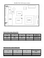
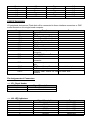
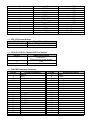
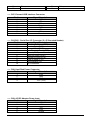
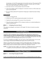
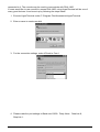
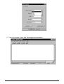
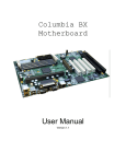
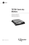
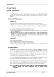
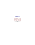
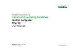
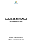
PNA-1800 Series
Communications Appliance
User?s Manual
Portwell Inc.
3F, No. 92, Nei-Hu Rd., Sec. 1, Taipei 114, Taiwan, R.O.C.
Headquarter: +886-2-2799-2020
Fax: +886-2-2799-1010
www.portwell.com.tw E-mail: [email protected]
Table of Contents
Chapter 1
Chapter 2
Introduction .................................................................................................................2
1.1
About This Manual .........................................................................................2
1.2
Manual Organization ......................................................................................2
1.3
Technical Support Options .............................................................................3
Getting Started ............................................................................................................4
2.1
Included Hardware .........................................................................................4
2.2
Before You Begin ...........................................................................................4
2.3
The Chassis....................................................................................................5
2.4
Opening the Chassis......................................................................................5
2.5
Installing a Hard Disk Drive............................................................................6
2.6
Installing a CF (Compact Flash) Card............................................................8
2.7
Upgrading the RAM Module...........................................................................9
2.8
Replace the Battery ......................................................................................10
2.9
Assembling the System ................................................................................11
2.10
Configuring the System Board .....................................................................12
2.11
Installing a Different Processor ....................................................................18
2.12
Installing Memory ........................................................................................19
2.13
Using a Client Computer ..............................................................................19
Chapter 3
Operation Guides ......................................................................................................23
3.1
Brief Guide for PPAP-100W........................................................................................23
3.2
Installing LAN Port Card .............................................................................................25
PNA-1800 User’s Manual
1
Chapter 1
1.1
Introduction
About This Manual
This manual describes all required information for setting up and using the PNA-1800 series
products.
PNA-1800 series products provide the essential components for delivering optimal
performance and functionality in the value communications appliance market segment. This
manual should help its users to get familiar with PNA-1800 series products to be able to fulfill
requirements.
Features of PNA-1800 series products includes:
Versatile networking and I/O capabilities: 3/4/6 choice of Ethernet ports (optional per model)
◆ Support one compact flash card or one 2.5” HDD per IDE channel
◆ Two USB ports
◆ Two available COM ports
◆ One on-board DMA33 IDE channel to support two IDE hard disk drives
◆ One PCI expansion slot
◆
1.2
Manual Organization
The manual describes how to configure your PNA-1800 system to meet various operating
requirements. It is divided into three chapters, with each chapter addressing a basic concept
and operation of this whole system.
Chapter 1: Introduction. It’s a briefing of the whole documentation and has some guidelines for
users who do not want to read through all the pages, but still finding what they need.
Chapter 2: Hardware Configuration Setting and Installation. This chapter shows how the
hardware was put together. Detail information is also included in this section of this
article. It shows the definitions and locations of Jumpers and Connectors that you
can easily configure your system. Descriptions on how to properly mount the CPU
and main memory to get a safe installation. By reading this chapter, the users
should be able to set up PNA-1800.
Chapter 3: Operation Information. It illustrates the main board system architecture. This section
intends to give the users more information on the system architecture and how its
performance can be maximized.
Any updates to this manual, technical clarification, and answers to frequently asked questions
will be posted on the following web site: http://www.portwell.com.tw/technical.htm
PNA-1800 User’s Manual
2
1.3
Technical Support Options
Users may find helpful tips or related information on Portwell's Web site.
http://www.portwell.com.tw. A direct contact to Portwell's technical person is also available.
For further support, users may also contact our headquarter in Taipei or contact Portwell's
distributors.
PNA-1800 User’s Manual
3
Chapter 2
Getting Started
This section describes how the hardware installation and system settings should be done.
2.1
Included Hardware
The following hardware are included in your kit:
◆
◆
◆
◆
◆
◆
◆
PPAP-100W net appliance system board
Vertical 3-Slot (2xPCI) PICMG Backplane
PNA-N106F3/ F4/F6 Ethernet LAN port board
125 W power supply
1U Chassis
One CPU and one SODIMM
One NULL cable
2.2
Before You Begin
To prevent damage to any system board, it is important to handle it with care. The following
measures are generally sufficient to protect your equipment from static electricity discharge:
When handling the board, use a grounded wrist strap designed for static discharge elimination.
Touch a grounded metal object before removing the board from the antistatic bag. Handle the
board by its edges only; do not touch its components, peripheral chips, memory modules or
gold contacts.
When handling processor chips or memory modules, avoid touching their pins or gold edge
fingers. Put the value communications appliance system board and peripherals back into the
antistatic bag when they are not in use or not installed in the chassis.
Some circuitry on the system board can continue to operate even though the power is switched
off. Under no circumstances should the Lithium coin cell that is being used to power the realtime clock be allowed to be shorted. The coin cell can heat under these conditions and present
a burn hazard.
Warning : This guide is for technically qualified personnel who have experience installing and
configuring system boards Disconnect the system board power supply from its
power source before you connect or disconnect cables or install or remove any
system board components. Failure to do this can result in personnel injury or
equipment damage.
Warning : Avoid short-circuiting the lithium battery; this can cause it to superheat and cause
burns if touched.
Warning : Do not operate the processor without a thermal solution. Damage to the processor
can occur in seconds.
PNA-1800 User’s Manual
4
2.3
The Chassis
The system is integrated in a standard 19" 1U chassis and fits in all standard rack or cabinet
(Fig. 2-1 , Fig. 2-2). Front accessible are an EZIO (For PNA-1810 only), one RS-232 port, two
USB ports, on PCI-expansion slot and a set of LAN ports. The LAN ports number (3, 4 or 6)
can be different according to model.
Fig. 2-1 Front View of the Chassis
Fig. 2-2 Rear View of the Chassis
PCI Expansion Slot
USB Ports
RS-232
LED Panel
EZIO
LAN Ports
4cm Fan
Power AC
in
Fig. 2-3 Function description of front and rear panel
2.4
Opening the Chassis
To open the chassis, follow below steps: (Fig. 2-4 to Fig. 2-5)
Fig. 2-4 Remove the screw by hand or
PNA-1800 User’s Manual
Fig. 2-5 Slide lightly the top-cover to rear side
5
screwdriver on the rear panel
2.5
until it is stopped and then raise it up
Installing a Hard Disk Drive
The system has a internal drive bay for one 2.5" hard disk drive or CF(Compact Flash) adaptor
board. If the HDD is not pre-installed, you can install by yourself. Please follow steps form Fig.
2-6 to Fig.20. Before you install HDD, you need the parts from the accessory-bag as shown on
Fig. 2-6. They are one HDD-bracket, several screws and one 44pin IDE cable.
2.5" hard disk (optional)
HDD-bracket
44pin IDE
Fig. 2-6
Fig. 2-7 Fix the hard disk drive on the HDD
bracket with four sink -head screws
PNA-1800 User’s Manual
Fig. 2-8 Plug the IDE cable into hard disk
drive connector
Note : Red cable have to aim at first pin on
hard disk drive and PPAP-100 CPU
board
6
Fig. 2-9 The half assembled hard disk drive
Fig. 2-11 Take away the CF-adaptor board
Fig. 2-10 Remove the screws
Fig. 2-12 Remove three round-head screws
and one plastic hex-stand-off
Attached in accessory-bag
Fig. 2-13 Remove all connecters (except
USB connector), then pull out
PPAP-100W CPU board vertically
PNA-1800 User’s Manual
Fig. 2-14 Long and short plastic hex-stand-off
and nut
7
Fig. 2-15 Remove plastic nut and pull out
long plastic hex-stand-off
Fig. 2-16 Replaced long plastic hex-stand-off
with short plastic hex-stand-off and
then fix plastic nuts
Fig. 2-17 Replace the PPAP-100W CPU
Board
Fig. 2-18 Replace long plastic hex -stand-off
with short plastic hex-stand-off, then
fix it and three round-head screws
on the corner
Fig. 2-19 Plug the cable into the connector
on PPAP-100W CPU card
Fig. 2-20 Place the hard disk drive over the
PPAP-100W CPU card, then fix the
four round-head screws in four
plastic hex-stand-off holes
2.6
Installing a CF (Compact Flash) Card
1. The adaptor board for compact flash card is over the PPAP-100W SBC and in the middle
PNA-1800 User’s Manual
8
front in the chassis (Fig. 2-21)
2. To install a compact flash card, it needs only to insert the CF card into the white socket on
the adaptor board (Fig. 2-22)
Fig. 2-21
2.7
Fig. 2-22
Upgrading the RAM Module
In case of upgrading system RAM module, follow these steps:
1. Remove the screws on four corners, then pull out the CF-adaptor board vertically. (Fig.2-23)
2. The RAM module lies directly under the CF-adaptor board (Fig.2-24). Pull out the lock arms
on both side and the RAM module springs up automatically.
Fig. 2-23
Fig. 2-24
4. Pull out the old module and then insert the new one (Fig.2-25).
5. Press down gently on both left and right edges of the module (Fig.2-26) until it "clicks".
PNA-1800 User’s Manual
9
Fig. 2-25
Fig. 2-26
7. Then reverse step 1 to install back the CF-adaptor board.
2.8
Replace the Battery
In case of replacing the battery, follow these steps:
Fig. 2-27
Fig. 2-28
1. The same procedure as upgrading RAM module, step 1.
2. Press the metal hook backward. (Fig.2-27)
3. The battery springs automatically. (Fig.2-28)
PNA-1800 User’s Manual
10
Fig. 2-29
4. Replace a new one and press it back with fingertip. (Fig.2-29)
2.9
Assembling the System
The mechanism of top cover assembly to chassis is very user friendly and needs only two
screws by hand on rear panel to fix the top cover. However, by assembling the top cover one
has to notice that the hooks must get in the proper position so that the top cover can fit the
chassis.
1. Lay the top cover properly above the chassis (Fig.2-30,31) and make sure that all four
hooks are in the right position.
2. Push the top cover towards to the front side. (Fig.2-32)
3. Fix the screws by hand or screwdriver (Fig.2-33)
PNA-1800 User’s Manual
11
Fig. 2-30
Fig. 2-31
Fig. 2-32
Fig.-2-33
2.10 Configuring the System Board
2.10.1
Product Specifications
Main processor
?? Intel® FC-PGA Celeron™ /Pentium® III Processors
(66/100 MHz system bus only)
BIOS
?? Award system BIOS with 256KB Flash ROM to support DMI, PnP,
Green function, Redirect to console.
Main Memory
?? One 144-pin SODIMM socket, supporting 3.3V SDRAM up to
256MB
L2 Cache Memory
?? 128KB/256KB PBSRAM built in (Celeron™ /Pentium® III) CPU
module
Chipset
PNA-1800 User’s Manual
?? Intel® 440BX AGPset
12
IDE Interface
?? One on-board DMA33 IDE channel to support two IDE devices
Default support 2.5" IDE devices only
Serial Ports
?? One DB9 Connector for connecting to console
?? One internal Pin pair connector for optional LCD/Key pad module
(Portwell Proprietary)
USB Interface
?? Support two USB ports for high speed I/O peripheral devices
Auxiliary I/O
Interfaces
?? System reset switch, Power LED, LAN activity LED, Power On/Off
Watchdog Timer
?? 0.5,1,2,4,8,16,32,64 sec. time-out intervals by jumper setting or 255
button and HDD LED interface
intervals from 0.5 min. to 254.5 min. by software programming
Power Inlet
?? One standard 20-pin ATX power connector, with power
button pin
?? One on-board DC input jack
I2C
?? One I2C interface connector
PCI Golden Finger
?? One PCI golden finger edge connector for PCI connection
Disk-On-Chip Feature
?? One 32-pin socket for M-system Flash Disk up to 288MB
Hardware Monitor
On-board hardware monitor for:
?? CPU fan x 1
?? Chassis fan x 2
?? System voltages: +5V and +12V
Power Good
?? On-board power good generator with reset time, 300ms~500ms
2.10.2
Hardware Configuration Setting
This section gives the definitions and shows the positions of jumpers, headers and connectors.
All of the configuration jumpers on PPAP-100W are in the proper position. The default settings
set by factory are marked with a star ( ? ).
2.10.2.1 Jumpers
In general, jumpers on the single board computer are used to select options for certain features.
Some of the jumpers are user-configurable, which allows system enhancement. The others are
for testing purpose only and should not be altered. To select any option, cover the jumper cap
over (Short) or remove (NC) it from the jumper pins according to the following instructions.
Here NC stands for "Not Connected". (Please refer to Fig. 2-34 for detail jumper positions)
PNA-1800 User’s Manual
13
Fig.2-34 PPAP-100W Jumper Locations
Disk-On-Chip Jumper Setting (JP3)
1-2
3-4
5-6
7-8
Short
NC
NC
NC
NC
Short
NC
NC
NC
NC
Short
NC
NC
NC
NC
Short
Memory address
Window
D0000-D1FFF?
D2000-D3FFF
D4000-D5FFF
D6000-D7FFF
Watch-Dog Timer Jumper Setting (JP7)
5-6
3-4
1-2
Time-Out Interval
(TWD)
Short
Short
Short
Short
Short
NC
0.5 Sec.
1 Sec. ?
PNA-1800 User’s Manual
14
Short
Short
NC
NC
NC
NC
NC
NC
Short
Short
NC
NC
Short
NC
Short
NC
Short
NC
2 Sec.
4 Sec.
8 Sec.
16 Sec.
32 Sec.
64 Sec.
2.10.2.2 Connectors
I/O peripheral devices and Flash disk will be connected to these interface connectors or DOC
socket located on this single board computer.
Connector
JP1
JP6
JP9
JP10
JP11
JP12
CN1
CN2
CN3
CN4
CN5
CN7
CN8
CN9
CN10
CN11
CN12
Function
Remark
System Reset Header
LED Indicator
ATX Power Control Button
Chassis Fan 1 Monitor Header
Chassis Fan 2 Monitor Header
CPU Fan Monitor Header
COM 1
ATX Power Connector
COM 2
Pitch 2.0mm 44-pin Hard Drive
Connector
Dual RJ-45 Ethernet Ports
Dual USB Ports
2.5”/3.5” Hard Drive Power
Connector
AD/DC Adaptor Power Input
Jack
ATX Power Control Connector Connect to backplane
I2C External Interface
Compact flash Socket for IDE On solder side
Interface
Pin Assignments of Connectors
?? JP1: Reset Header
Pin No.
1
2
?? J06: LED Indicators
Pin No.
1
2
3
4
5
6
PNA-1800 User’s Manual
Signal Description
Reset
Ground
Signal Description
Link A
GPO0
Active A
GPO8
10/100 A
GPO24
Type
Yellow LED
Yellow LED
Yellow LED
Yellow LED
Yellow LED
Yellow LED
15
7
8
9
10
11
12
13
14
15
16
17
18
19
20
Link B
GPO25
Active B
GPO26
10/100 B
GPO27
HDD LED
GPO28
Power LED
GPO29
Ground
5VSB
SW ON
System H/W Reset
Yellow LED
Yellow LED
Yellow LED
Yellow LED
Yellow LED
Yellow LED
Red LED
Yellow LED
Green LED
Yellow LED
Wire/Cable
Wire/Cable
Wire/Cable
Wire/Cable
?? JP9: ATX Power Button
Pin No.
Signal Description
1
Power Button Control Signal
2
Ground
?? JP10/JP11/JP12: Chassis/CPU Fan Header
Pin No.
Signal Description
1
Pull-Up 5V
(Reserved for sense signal)
2
+12V
3
Ground
?? CN4: IDE Interface Connector
Pin No.
Signal Description
1
Reset #
3
Data 7
5
Data 6
7
Data 5
9
Data 4
11
Data 3
13
Data 2
15
Data 1
17
Data 0
19
Ground
21
DMA REQ
23
IOW #
25
IOR #
27
IOCHRDY
29
DMA ACK #
31
INT REQ 14
33
DAI
35
DA0
37
CS1
39
HDD Active #
PNA-1800 User’s Manual
Pin No.
2
4
6
8
10
12
14
16
18
20
22
24
26
28
30
32
34
36
38
40
Signal Description
Data 7
Data 8
Data 9
Data 10
Data 11
Data 12
Data 13
Data 14
Data 15
N/C
Ground
Ground
Ground
Pull-Down
Ground
CS16
N/C
DA2
CS3
Ground
16
41
43
+5V
Ground
42
44
+5V
Ground
?? CN7: External USB Interface Connector
Pin No.
Signal Description
1
OC0
2
P03
P0+
4
Ground
5
OC1
6
P17
P1+
8
Ground
?? CN1/CN3 : Serial Port 1/2 Connector (2 x 5 Shrouded Header)
Pin No.
Signal Description
1
Data Carrier Detect (DCD)
2
Receive Data (RXD)
3
Transmit Data (TXD)
4
Data Terminal Ready (DTR)
5
Ground (GND)
6
Data Set Ready (DSR)
7
Request to Send (RTS)
8
Clear to Send (CTS)
9
Ring Indicator (RI)
10
No Connection
?? CN8: Hard Disk Power Connector
Pin No.
Signal Description
1
+12V
2
GND
3
GND
4
VCC (+5V)
?? CN9: AC/DC Adaptor Power Input
Pin No.
Signal Description
1
+5V
2
+12V
3
+5V
4
+12V
5
Ground
PNA-1800 User’s Manual
17
?? CN11: SM-Bus Interface
Pin No.
1
2
3
4
Signal Description
+5V
SMB-Data
SMB-CLK
Ground
?? CN12: Compact Flash Socket
Pin No.
Signal Description
1
Ground
2
D3
3
D4
4
D5
5
D6
6
D7
7
CS1
8
A10
9
Output Enable
10
A9
11
A8
12
A7
13
+5V
14
A6
15
A5
16
A4
17
A3
18
A2
19
A1
20
A0
21
D0
22
D1
23
D2
24
CS16
25
CD2
Pin No.
26
27
28
29
30
31
32
33
34
35
36
37
38
39
40
41
42
43
44
45
46
47
48
49
50
Signal Description
CD1
D11
D12
D13
D14
D15
CS3
VS1
IOR
IOW
Write Enable
IRQ
+5V
CSEL
VS2
Reset
IORDY
DREQ
DACK
VD2
VD1
D8
D9
D10
Ground
?? CN10: ATX Power Control
Pin No.
Signal Description
1
Power OK
2
5v Standby
3
Power On
4
Ground
2.11 Installing a Different Processor
Installing CPU
1. Lift the handling lever of CPU socket outwards and upwards to the other end.
2. Align the processor pins with holes on the socket. Make sure that the notched corner or
PNA-1800 User’s Manual
18
dot mark (pin 1) of the CPU corresponds to the socket's bevel end. Then press the CPU
gently until it fits into place. If this operation is not easy or smooth, don't do it forcibly.
You need to check and rebuild the CPU pin uniformly.
3. Push down the lever to lock processor chip into the socket.
4. Follow the installation guide of cooling fan or heat sink to mount it on CPU surface and
lock it on the socket 370.
5. Be sure to follow particular CPU speed and voltage type to adjust the jumper settings
properly.
Removing CPU
1. Unlock the cooling fan first.
2. Lift the lever of CPU socket outwards and upwards to the other end.
3. Carefully lift up the existing CPU to remove it from the socket.
4. Follow the steps of installing a CPU to change to another one or place handling bar to
close the opened socket.
2.11.1
Configuring Processor Speed
The system was designed to self-detect its CPU speed. So it does not require any system
adjustment.
2.12 Installing Memory
This PPAP-100W provides one 144-pin SODIMM socket. The maximum memory size is
128MB. Normally, the SODIMM used could be either 3.3V EDO (Extended Data Out) memory
with speed less than 70ns or 3.3V SDRAM (Synchronized DRAM) with speed less than 100ns
(-10). If you adopt 100MHz system clock, you need to use SODIMM with speed less than 80ns
(-8). It is better to use PC100-compliant memory chip on your system.
For system compatibility and stability, don't use memory module without brand. You can also
use the single or double-side SODIMM without parity check and ECC function.
Watch out the contact and lock integrity of memory module with socket, it will impact on the
system reliability. Follow normal procedure to install your DRAM module into memory socket.
Before locking, make sure that the module has been fully inserted into card slot.
NOTE: For maintaining system stability, don't change any of DRAM parameters in BIOS setup
to upgrade your system performance except for getting technical information.
2.13 Using a Client Computer
2.13.1
Connecting Using HyperTerminal
If users use a headless PNA-1800, which should have no mouse/keyboard and VGA output
PNA-1800 User’s Manual
19
connected to it. The console may be used to communicate with PNA-1800
If users would like to use console to access PNA-1800, using HyperTerminal will be one of
many good choices. It can be set up by following the steps below:
1. Execute HyperTerminal under C:\Program Files\Accessories\HyperTerminal
2. Enter a name to create new dial
3. For the connection settings, make it Direct to Com1.
4. Please make the port settings to Baud rate 19200,Parity None,Data bits 8,
Stop bits 1.
PNA-1800 User’s Manual
20
5. Turn on the power of raid, after following screen was shown
PNA-1800 User’s Manual
21
6. You can then see the boot up information of PNA-1800
7. This is the end of this section. If the terminal did not port correctly, please check the
previous steps.
PNA-1800 User’s Manual
22
Chapter 3
3.1
Operation Guides
Brief Guide for PPAP-100W
The PPAP-100W all-in-one half-sized network appliance system board is designed to fit a high
performance Celeron™ and Pentium® III based processor and compatible for high-end
computer system application. It is made to meet today's demanding pace, and keep complete
compatibility with hardware and software designed for the IBM PC/AT. It's beneficial to build up
a high performance and high data availability system for VARs, or system integrators.
This single board computer can run with Intel® FC-PGA Celeron™ (100MHz system bus only)
or Intel® FC-PGA Pentium® III processors (100MHz system bus only), and 144-pin SDRAM up
to 128MB DRAM. The enhanced on-board PCI IDE interface support 2 drives up to PIO mode
4 timing and Ultra DMA/33 synchronous mode feature. The on-board Super I/O Chipset
integrates only two serial ports, which are driven by two high performance 16C550-compatible
UARTs to provide 16-byte send/receive FIFOs. Besides, the two Universal Serial Bus ports
provide high-speed data communication between peripherals and PC.
The on-board 32-pin DIP socket supports M-system Disk-On-Chip Flash disk up to 288MB. A
built-in Watch-dog Timer function helps to monitor your system status. The on-board Flash
ROM is used to make the BIOS update easier. An AC/DC adaptor power input jack is provided
for AT mode operation. The high precision Real Time Clock/calendar is built to support Y2K for
accurate scheduling and storing configuration information. All of these features make PPAP100W excellent in stand-alone applications.
Fig. 3-1
System Architecture
The following illustration of block diagram will show you how PPAP-100W gives you a highly
integrated system solution. The most up-to-date system architecture of PPAP-100W, includes
two main VLSI chips, 82443BX Host Bridge and 82371EB PIIX4E, to support FC-PGA
Celeron/PIII processor, SODIMM, PCI bus interface, USB port, SMBus communication, and
Ultra DMA/33 IDE Master. The on-board super I/O chip, W83977ATF, supports two UARTs.
PPAP-100W built-in Socket 370 to support Intel® FC-PGA Celeron™ /Pentium® III processor
(both for 100MHz system bus only) for high performance and cost-effective application. The
Intel® Celeron™ processor is the next addition to the P6 micro architecture processor product
PNA-1800 User’s Manual
23
lines. The Intel® Celeron™ processor, like the Intel Pentium Pro and Intel Pentium II processor,
features a Dynamic Execution micro-architecture and also executes MMX technology
instructions for enhanced media and communication performance. However, the FC-PGA
Coppermine-256 (Pentium® III) processor provides twice the Celeron™ L2 Cashe.
The North Bridge 82443BX provides a completely integrated solution for the system controller
and data path components in a Celeron™ processor system. It provides a 64-bit GTL+ based
host bus interface, optimized 64-bit DRAM interface with ECC to support two 3.3V DIMMs at
the maximum bus frequency of 100 MHz, and 32-bit PCI bus interface to support on-board PCI
device.
The South Bridge, 82371EB PCI ISA IDE Xcelerator (PIIX4), provides a highly integrated
multifunction PCI-to-ISA bridge solution for the best industry application. It supports 1-channel
dedicated Ultra DMA-33 IDE master interface, full Plug-and-Play compatibility, and Advanced
Programmable Interrupt Controller (APIC) interface on PPAP-100W. It also supports 2-port
Universal Serial Bus (USB) and PCI 2.1 Compliance operation. In addition, it also provides XDbus via buffer logic control to support BIOS read/write access and South Bridge internal Realtime Clock (RTC) to maintain date and time of a system.
The Super I/O chip W83977ATF integrates two high-speed serial ports.In PPAP-100W, it
contains Watch-dog Timer (WDT) enabled by jumper setting and Disk-On-Chip (DOC) for Msystem Flash disk. Besides, an advanced feature is used on PPAP-100W to support detection
of CPU temperature.
The two on-board Ethernet devices, powered by Intel® 82559 10/100 Base-T Fast Ethernet
Controller supports Fast Ethernet interface through RJ-45 port.
All detailed operating relations are shown in Fig. 3-2 PPAP-100W System Block Diagram.
PNA-1800 User’s Manual
24
Fig.3-2 PPAP-100W System Block Diagram
3.2
Installing LAN Port Card
The following table indicates the settings of PNA-N106B/C.
Jumper Setting for PNA-N106B/C
1. LAN Device Select: JP3,JP5,JP6,JP8,JP9,JP11
Jumper
Front
Back
JP5
JP6
JP9
JP3
JP8
JP11
Device
Loc.
U1
U3
U5
U7
U9
U30
Function
Enable
Disable
1-2(Short)
2-3(Short)
1-2(Short)
2-3(Short)
1-2(Short)
2-3(Short)
1-2(Short)
2-3(Short)
1-2(Short)
2-3(Short)
1-2(Short)
2-3(Short)
2. LAN Chips & V I/O voltage Select: JP1
PNA-1800 User’s Manual
25
3.3V
VCC3
5V
Chip
1-3 & 2-4
3-5 & 4-6
×
VI/O
×
×
7-9 & 8-10
Default ? 3-5 Short & 4-6 Short
3. JP2
2-3 Short --> for Intel® PCI to PCI Bridge
1-2 Short --> for Hinet PCI to PCI Bridge
PNA-1800 User’s Manual
26