1
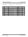
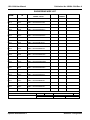
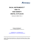
RACAL INSTRUMENTS™
1260-138A
MULTIPLEXER PLUG-IN
Publication No. 980824-138A Rev. A
Astronics Test Systems Inc.
4 Goodyear, Irvine, CA 92618
Tel: (800) 722-2528, (949) 859-8999; Fax: (949) 859-7139
[email protected] [email protected]
[email protected] http://www.astronicstestsystems.com
Copyright 1999 by Astronics Test Systems Inc. Printed in the United States of America. All rights reserved. This
book or parts thereof may not be reproduced in any form without written permission of the publisher.
THANK YOU FOR PURCHASING THIS
ASTRONICS TEST SYSTEMS PRODUCT
For this product, or any other Astronics Test Systems product that incorporates software drivers, you
may access our web site to verify and/or download the latest driver versions. The web address for
driver downloads is:
http://www.astronicstestsystems.com/support/downloads
If you have any questions about software driver downloads or our privacy policy, please contact us at:
[email protected]
WARRANTY STATEMENT
All Astronics Test Systems products are designed to exacting standards and manufactured in full
compliance to our AS9100 Quality Management System processes.
This warranty does not apply to defects resulting from any modification(s) of any product or part
without Astronics Test Systems express written consent, or misuse of any product or part. The
warranty also does not apply to fuses, software, non-rechargeable batteries, damage from battery
leakage, or problems arising from normal wear, such as mechanical relay life, or failure to follow
instructions.
This warranty is in lieu of all other warranties, expressed or implied, including any implied warranty of
merchantability or fitness for a particular use. The remedies provided herein are buyer’s sole and
exclusive remedies.
For the specific terms of your standard warranty, contact Customer Support. Please have the following
information available to facilitate service.
1. Product serial number
2. Product model number
3. Your company and contact information
You may contact Customer Support by:
E-Mail:
[email protected]
Telephone:
+1 800 722 3262
(USA)
Fax:
+1 949 859 7139
(USA)
RETURN OF PRODUCT
Authorization is required from Astronics Test Systems before you send us your product or sub-assembly for
service or calibration. Call or contact Customer Support at 1-800-722-3262 or 1-949-859-8999 or via fax at 1-949859-7139. We can also be reached at: [email protected].
If the original packing material is unavailable, ship the product or sub-assembly in an ESD shielding bag and use
appropriate packing materials to surround and protect the product.
PROPRIETARY NOTICE
This document and the technical data herein disclosed, are proprietary to Astronics Test Systems, and shall not,
without express written permission of Astronics Test Systems, be used in whole or in part to solicit quotations from
a competitive source or used for manufacture by anyone other than Astronics Test Systems. The information
herein has been developed at private expense, and may only be used for operation and maintenance reference
purposes or for purposes of engineering evaluation and incorporation into technical specifications and other
documents which specify procurement of products from Astronics Test Systems.
TRADEMARKS AND SERVICE MARKS
All trademarks and service marks used in this document are the property of their respective owners.
•
Racal Instruments, Talon Instruments, Trig-Tek, ActivATE, Adapt-A-Switch, N-GEN, and PAWS are
trademarks of Astronics Test Systems in the United States.
DISCLAIMER
Buyer acknowledges and agrees that it is responsible for the operation of the goods purchased and
should ensure that they are used properly and in accordance with this document and any other
instructions provided by Seller. Astronics Test Systems products are not specifically designed,
manufactured or intended to be used as parts, assemblies or components in planning, construction,
maintenance or operation of a nuclear facility, or in life support or safety critical applications in which
the failure of the Astronics Test Systems product could create a situation where personal injury or
death could occur. Should Buyer purchase Astronics Test Systems product for such unintended
application, Buyer shall indemnify and hold Astronics Test Systems, its officers, employees,
subsidiaries, affiliates and distributors harmless against all claims arising out of a claim for personal
injury or death associated with such unintended use.
FOR YOUR SAFETY
Before undertaking any troubleshooting, maintenance or exploratory procedure, read carefully the WARNINGS
and CAUTION notices.
This equipment contains voltage hazardous to
human life and safety, and is capable of inflicting
personal injury.
If this instrument is to be powered from the AC line (mains) through an autotransformer,
ensure the common connector is connected to the neutral (earth pole) of the power
supply.
Before operating the unit, ensure the conductor (green wire) is connected to the ground
(earth) conductor of the power outlet. Do not use a two-conductor extension cord or a
three-prong/two-prong adapter. This will defeat the protective feature of the third
conductor in the power cord.
Maintenance and calibration procedures sometimes call for operation of the unit with
power applied and protective covers removed. Read the procedures and heed warnings
to avoid “live” circuit points.
Before operating this instrument:
1. Ensure the proper fuse is in place for the power source to operate.
2. Ensure all other devices connected to or in proximity to this instrument are properly grounded or connected to
the protective third-wire earth ground.
If the instrument:
-
fails to operate satisfactorily
shows visible damage
has been stored under unfavorable conditions
has sustained stress
Do not operate until performance is checked by qualified personnel.
This page was left intentionally blank.
Publication No. 980824-138A Rev. A
1260-138A User Manual
Table of Contents
Chapter 1 ............................................................................................................................ 1-1
SPECIFICATIONS ........................................................................................................................ 1-1
Introduction ............................................................................................................................... 1-1
Specifications ............................................................................................................................ 1-2
Ordering Information ................................................................................................................. 1-4
Chapter 2 ............................................................................................................................ 2-1
INSTALLATION INSTRUCTIONS ................................................................................................ 2-1
Unpacking and Inspection ......................................................................................................... 2-1
Installation ................................................................................................................................. 2-2
Module Configuration ................................................................................................................ 2-2
Configuration Relays ................................................................................................................. 2-5
Analog Bus Relays .................................................................................................................... 2-6
Connector Pin Assignments ...................................................................................................... 2-6
Front Panel Connector .............................................................................................................. 2-9
Mating Connectors............................................................................................................... 2-11
Astronics Test Systems
i
1260-138A User Manual
Publication No. 980824-138A Rev. A
Chapter 3 ............................................................................................................................ 3-1
MODULE OPERATION ................................................................................................................ 3-1
Setting the Module Address ...................................................................................................... 3-1
Operating Modes....................................................................................................................... 3-2
Operating In Message-Based Mode .......................................................................................... 3-4
Channel Descriptors For The 1260-138A .............................................................................. 3-4
Reply To The MOD:LIST? Command .................................................................................... 3-5
Operating The 1260-138A in Register-Based Mode .................................................................. 3-5
Configuring Larger Multiplexers................................................................................................. 3-8
Creating Very Large Multiplexers With the Analog Bus ............................................................. 3-9
1260-138A Example Code ................................................................................................... 3-11
Chapter 4 ............................................................................................................................ 4-1
OPTIONAL ASSEMBLIES ............................................................................................................ 4-1
ii
Astronics Test Systems
Publication No. 980824-138A Rev. A
1260-138A User Manual
List of Figures
Figure 1-1, The 1260-138A ................................................................................................................. 1-1
Figure 2-1, Single Multiplexer Example (Channels 50 through 57) ..................................................... 2-2
Figure 2-2, Block Diagram of 1260-138A ............................................................................................ 2-4
Figure 2-3, 1260-138A Module Configuration Block Diagram. ............................................................ 2-5
Figure 2-4, 1260-138A Multiplexer Configuration Block Diagram ........................................................ 2-5
Figure 2-5, Front-Panel Connector Pin Numbering ........................................................................... 2-10
Figure 3-1, Front View – Module Addresses for 1 through 6 ............................................................... 3-1
Figure 3-2, Front View – Module Addresses for 7 through 12 ............................................................. 3-2
Figure 3-3, Message-Based Mode of Operation ................................................................................. 3-3
Figure 3-4, Register-Based Mode of Operation .................................................................................. 3-3
Astronics Test Systems
iii
1260-138A User Manual
Publication No. 980824-138A Rev. A
List of Tables
Table 2-1, Command Arguments for Interconnecting the Muxes ........................................................ 2-6
Table 2-2, Command Arguments for Connecting to the Analog Bus ................................................... 2-6
Table 2-3, 1260-138A Front-Panel Connections for J200 ................................................................... 2-7
Table 3-1, Control Register Channel Assignments ............................................................................. 3-7
iv
Astronics Test Systems
Publication No. 980824-138A Rev. A
1260-138A User Manual
.
DOCUMENT CHANGE HISTORY
Revision
Date
A
9/18/08
No change
04/21/09
Astronics Test Systems
Description of Change
Revised per EO 29391
Revised format to current standards. Company
name revised throughout manual. Manual now
revision letter controlled. Added Document
Change History Page v.
Back of cover sheet.
Revised Warranty
Statement, Return of Product, Proprietary Notice
and Disclaimer to current standards. Removed
Reshipment Instructions in (Chap. 2-1) and
removed (Chap 5). Information. Now appears in
first 2 sheets behind cover sheet. Updated table
of contents to reflect changes made. .
v
1260-138A User Manual
Publication No. 980824-138A Rev. A
This page was left intentionally blank.
vi
Astronics Test Systems
Publication No. 980824-138A Rev. A
1260-138A User Manual
Chapter 1
SPECIFICATIONS
Introduction
The 1260-138A is a plug-in switch module developed for the
1260-100 Adapt-a-Switch Platform. The 1260-138A includes the
following features:
•
Standard Adapt-a-Switch plug-in design, providing for ease
of replacement.
•
Data-driven embedded descriptor, allowing immediate use
with any Option-01T switch controller, regardless of
firmware revision level.
•
Capability of combining multiple multiplexers on-board to
form large multiplexers.
•
Analog bus for combining multiple 1260-138A plug-ins, to
form very large multplexers.
Figure 1-1, The 1260-138A
Astronics Test Systems
Specifications 1-1
1260-138A User Manual
Specifications
Publication No. 980824-138A Rev. A
Bandwidth (-3 dB)
1x8
1 x 64
> 85 MHz
> 4 MHz
Insertion Loss (1 x 8)
100KHz:
1MHz:
10MHz:
30MHz:
< 0.1 dB
< 0.2 dB
< 1.7 dB
< 1.7 dB
Isolation (1 x 8)
100KHz:
1MHz:
10MHz:
30MHz:
> 88 dB
> 78 dB
> 44 dB
> 40 dB
Crosstalk (1 x 8)
100KHz:
1MHz:
10MHz:
30MHz:
< -63 dB
< -63 dB
< -41 dB
< -34 dB
Switching Voltage
AC
DC
250 V, Max
220 V, Max
Switching Current
AC
DC
2 A, Max
2 A, Max
Switching Power
AC
DC
125 VA, Max
60 W, Max
Path resistance
1 x 8: 500 mΩ
1 x 40: 650 mΩ
1 x 64: 800 mΩ
Thermal EMF
< 10 uV
Capacitance
(1 x 8) Channel to Chassis
(1 x 8) Open Channel
(1 x 8) High to Low
(1 x 64) High to Low
Specifications 1-2
Insulation resistance
> 109 Ω
Relay Settling Time
< 10 ms
< 150 pF
< 5 pF
< 110 pF
< 400 pF
Astronics Test Systems
Publication No. 980824-138A Rev. A
1260-138A User Manual
Shock
30g, 11 ms, ½ sine wave
Vibration
0.013 in. P-P, 5-55 Hz
Bench Handling
4 in., 45°
Cooling
See 1260-100 cooling data
Temperature
Operating
Non-operating
0°C to +55°C
-40°C to +75°C
Relative Humidity
Altitude
Operating
Non-operating
Power Requirements
+5 VDC
85% + 5% non-condensing at
< 30°C
10,000 feet
15,000 feet
150mA + 30mA per energized relay
(2A Max.)
MTBF
MIL-HDBK-217E
Bellcore
Relay Life Expectancy
Mechanical
Electrical
Astronics Test Systems
183,169 hours
154,107 hours
100,000,000 operations
100,000 operations at full rated load
(resistive)
Weight
1.0 lb. (0.45 kg.)
Dimensions
4.5”H X 0.75”W X 9.5”D
Specifications 1-3
1260-138A User Manual
Publication No. 980824-138A Rev. A
Listed below are part numbers for both the 1260-138A switch
module and available mating connector accessories. Each
1260-138A uses a single mating connector.
Ordering
Information
ITEM
DESCRIPTION
PART #
1260-138A Switch Module
Switch Module, 8 (1X8) 2 Wire Mux, 2
A
Consists of:
407723
P/N 405156 PCB Assembly
P/N 980824-138A Manual
160-pin Mating Connector
160 Pin Conn. Kit with pins
407664
Cable Assy. 6ft, Sleeved
160 Pin Cable Assy, 6 Ft, 24 AWG
407408-001
Additional Manual
1260-138A Manual
980824-138A
Specifications 1-4
Astronics Test Systems
Publication No. 980824-138A Rev. A
1260-138A User Manual
Chapter 2
INSTALLATION INSTRUCTIONS
Unpacking and
Inspection
1. Remove the 1260-138A module and inspect it for damage. If
any damage is apparent, inform the carrier immediately.
Retain shipping carton and packing material for the carrier’s
inspection.
2. Verify that the pieces in the package you received contain the
correct 1260-138A module option and the 1260-138A Users
Manual. Notify Customer Support if the module appears
damaged in any way. Do not attempt to install a damaged
module into a VXI chassis.
3. The 1260-138A module is shipped in an anti-static bag to
prevent electrostatic damage to the module. Do not remove
the module from the anti-static bag unless it is in a staticcontrolled area.
Astronics Test Systems
Installation Instructions 2-1
1260-138A User Manual
Installation
Publication No. 980824-138A Rev. A
Installation of the 1260-138A Switching Module into a 1260100/101 Adapt-a-Switch Carrier assembly is described in the
“Installation” section of the 1260-100/101 Adapt-a-Switch Carrier
manual.
For installation of the 1260-138A into a 1256 Switching System,
refer to the 1256 User Manual.
Module
Configuration
The 1260-138A contains eight 1x8 multiplexers, numbered from 0
through 7. Each multiplexer (mux) is made up of eight relays,
referred to as channels. Figure 2-1 shows an example of one of
these multiplexers (multiplexer 5). In this example, the inputs are
channels 50 through 57. The user may close one or more relays to
connect the inputs to the common output.
High
Low
Channel 50 Input
High
Low
Channel 51 Input
High
Low
Channel 52 Input
High
High
Mux 5 Common Output
Low
Channel 53 Input
Low
High
Low
Channel 54 Input
High
Low
Channel 55 Input
High
Low
Channel 56 Input
High
Channel 57 Input
Low
Figure 2-1, Single Multiplexer Example (Channels 50 through 57)
Installation Instructions 2-2
Astronics Test Systems
Publication No. 980824-138A Rev. A
1260-138A User Manual
Since each channel is independently controlled, the user can
simultaneously connect any combination of mux inputs to the
common output of the same multiplexer.
For example, referring to Figure 2-1, the user may connect the
channel 51 and channel 53 inputs to the common output by closing
the channel 51 and channel 53 relays at the same time. Taking this
concept further, the user could even close the relays for channels
50 through 57 all at the same time, connecting all of this
multiplexer’s inputs to its common output.
Figure 2-1 shows just one of the eight multiplexers on the
1260-138A. All eight multiplexers operate independently. For a
block diagram of the entire 1260-138A, refer to Figure 2-2. When
reviewing this diagram, keep in mind that the 1260-138A is a twowire switch product (each relay has two poles). Most applications
use one pole to switch the high side of a differential signal, and the
other pole to switch the low side.
Astronics Test Systems
Installation Instructions 2-3
1260-138A User Manual
Publication No. 980824-138A Rev. A
HIGH SIDE
LOW SIDE
PIN Channel
K0
K1
K2
K3
K4
K5
K6
K7
A3
MUX 0-1
Configuration
Relay
K8
K9
K10
K11
K12
K13
K14
K15
MUX 1-2
Configuration
Relay
10
11
12
13
14
15
16
17
K65 (200)
K16
K17
K18
K19
K20
K21
K22
K23
A9
MUX 2-3
Configuration
Relay
D12
E11
C10
D10
E9
C8
D6
C6
20
21
22
23
24
25
26
27
K66 (300)
K24
K25
K26
K27
K28
K29
K30
K31
A13
MUX 3-4
Configuration
Relay
D8
C14
D14
E13
C12
E15
D16
C16
30
31
32
33
34
35
36
37
K67 (400)
K32
K33
K34
K35
K36
K37
K38
K39
C15
MUX 4-5
Configuration
Relay
D18
C18
A16
B17
A18
D20
A24
B23
40
41
42
43
44
45
46
47
K68 (500)
K40
K41
K42
K43
K44
K45
K46
K47
C19
MUX 5-6
Configuration
Relay
D26
E25
C24
D24
E23
C22
D22
C20
50
51
52
53
54
55
56
57
K69 (600)
K48
K49
K50
K51
K52
K53
K54
K55
C25
MUX 6-7
Configuration
Relay
E21
C21
C28
D28
D29
E30
C30
D31
60
61
62
63
64
65
66
67
K70 (700)
K56
K57
K58
K59
K60
K61
K62
K63
A27
Analog Bus 3L
C4
E5
B7
A8
D19
B13
A12
B11
K74
(1000)
K73
(1001)
K72
(1002)
K71
(1003)
E32
C32
E27
C26
B29
A30
B31
A32
PIN Channel
00
01
02
03
04
05
06
07
K64 (100)
A5
Analog Bus 0L
Analog Bus 1L
Analog Bus 2L
D2
E1
A2
C1
C2
B3
E3
D4
70
71
72
73
74
75
76
77
GROUND PINS: A19, A20,
A21, A22, A25, A26, B5, B9,
B27, C5, C9, C27, D7, D17,
E7, E17
A4
MUX 0-1
Configuration
Relay
MUX 1-2
Configuration
Relay
00
01
02
03
04
05
06
07
K8
K9
K10
K11
K12
K13
K14
K15
B4
D5
C7
A7
E19
C13
A11
C11
10
11
12
13
14
15
16
17
K16
K17
K18
K19
K20
K21
K22
K23
E12
D11
B10
E10
D9
B8
E6
B6
20
21
22
23
24
25
26
27
K24
K25
K26
K27
K28
K29
K30
K31
E8
B14
E14
D13
B12
D15
E16
B16
30
31
32
33
34
35
36
37
K32
K33
K34
K35
K36
K37
K38
K39
E18
B18
A15
C17
A17
E20
A23
C23
40
41
42
43
44
45
46
47
K40
K41
K42
K43
K44
K45
K46
K47
E26
D25
B24
E24
D23
B22
E22
B20
50
51
52
53
54
55
56
57
K48
K49
K50
K51
K52
K53
K54
K55
D21
B21
B28
E28
E29
D30
B30
E31
60
61
62
63
64
65
66
67
K56
K57
K58
K59
K60
K61
K62
K63
D32
B32
D27
B26
C29
A29
C31
A31
70
71
72
73
74
75
76
77
K65 (200)
A10
MUX 2-3
Configuration
Relay
K66 (300)
A14
MUX 3-4
Configuration
Relay
K67 (400)
B15
MUX 4-5
Configuration
Relay
K68 (500)
B19
MUX 5-6
Configuration
Relay
K69 (600)
B25
MUX 6-7
Configuration
Relay
K70 (700)
A28
Analog Bus 3H
E2
D1
A1
B1
B2
C3
D3
E4
K64 (100)
A6
Analog Bus 0H
Analog Bus 1H
Analog Bus 2H
K0
K1
K2
K3
K4
K5
K6
K7
K74
(1000)
K73
(1001)
K72
(1002)
K71
(1003)
NOTE: Numbers in parentheses refer to channel numbers to use in commands.
Figure 2-2, Block Diagram of 1260-138A
Installation Instructions 2-4
Astronics Test Systems
Publication No. 980824-138A Rev. A
1260-138A User Manual
The 1260-138A is configurable for a variety of applications.
Referring back to Figure 2-2, there are seven configuration relays,
numbered K64 through K70. Figure 2-3 shows these relays from a
different perspective, identifying them with their channel numbers
(100, 200, etc.). Figure 2-4 shows a detailed view of the
components inside a multiplexer.
Configuration
Relays
1X8
2 WIRE
MUX
1X8
2 WIRE
MUX
1X8
2 WIRE
MUX
1X8
2 WIRE
MUX
1X8
2 WIRE
MUX
1X8
2 WIRE
MUX
1X8
2 WIRE
MUX
1X8
2 WIRE
MUX
MUX 00
MUX 01
MUX 02
MUX 03
MUX 04
MUX 05
MUX 06
MUX 07
100
200
300
400
500
600
700
Figure 2-3, 1260-138A Module Configuration Block Diagram.
HIGH
1X8
2 WIRE
MUX
2 WIRE
COMMON
MUX XX
LOW
CHANNEL 0XX0
HIGH
CHANNEL 0XX7
HIGH
LOW
LOW
100
Figure 2-4, 1260-138A Multiplexer Configuration Block Diagram
Table 2-1 shows the command arguments (channel numbers) for
connecting mux pairs together. For further details, refer to the
section entitled “Configuring Larger Multiplexers” in Chapter 3.
Astronics Test Systems
Installation Instructions 2-5
1260-138A User Manual
Publication No. 980824-138A Rev. A
Table 2-1, Command Arguments for Interconnecting the Muxes
MUX
Interconnection
0-1
1-2
2-3
3-4
4-5
5-6
6-7
Analog Bus
Relays
Command
Argument
(Channel)
(100)
(200)
(300)
(400)
(500)
(600)
(700)
Interconnect
Relay
K64
K65
K66
K67
K68
K69
K70
Pin
High
A5
A9
A13
C15
C19
C25
A27
Low
A6
A10
A14
B15
B19
B25
A28
For even greater flexibility, the 1260-138A takes full advantage of
the analog bus found in the 1260-100/101 Adapt-a-Switch Carrier
and 1256 Switching System. Four analog bus relays (K71 through
K74 in the lower left-hand corner of Figure 2-2) connect the output
of multiplexer 7 to any of the four analog bus pairs. For details on
using the analog bus, refer to the section “Creating Very Large
Multiplexers with the Analog Bus” in Chapter 3.
Table 2-2 shows the command arguments (channel numbers) for
connecting the mux 7 output to the analog bus.
Table 2-2, Command Arguments for Connecting to the Analog Bus
Analog
Bus
0
1
2
3
Connector Pin
Assignments
Installation Instructions 2-6
Command
Argument
(Channel)
(1000)
(1001)
(1002)
(1003)
Interconnect
Relay
K74
K73
K72
K71
Pin
High
A27
A27
A27
A27
Low
A28
A28
A28
A28
Table 2-3 provides the pin assignments for the front panel
connector.
Astronics Test Systems
Publication No. 980824-138A Rev. A
1260-138A User Manual
Table 2-3, 1260-138A Front-Panel Connections for J200
Mux
Channel
0
0
0
0
0
0
0
0
0
1
1
1
1
1
1
1
1
1
2
2
2
2
2
2
2
2
2
3
3
3
3
3
3
3
3
3
4
4
Mux 0 Common
0
1
2
3
4
5
6
7
Mux 1 Common
10
11
12
13
14
15
16
17
Mux 2 Common
20
21
22
23
24
25
26
27
Mux 3 Common
30
31
32
32
34
35
36
37
Mux 4 Common
40
Astronics Test Systems
Pin
High
A3
D2
E1
A2
C1
C2
B3
E3
D4
A5
C4
E5
B7
A8
D19
B13
A12
B11
A9
D12
E11
C10
D10
E9
C8
D6
C6
A13
D8
C14
D14
E13
C12
E15
D16
C16
C15
D18
Low
A4
E2
D1
A1
B1
B2
C3
D3
E4
A6
B4
D5
C7
A7
E19
C13
A11
C11
A10
E12
D11
B10
E10
D9
B8
E6
B6
A14
E8
B14
E14
D13
B12
D15
E16
B16
B15
E18
Installation Instructions 2-7
1260-138A User Manual
Publication No. 980824-138A Rev. A
Mux
Channel
4
4
4
4
4
4
4
5
5
5
5
5
5
5
5
5
6
6
6
6
6
6
6
6
6
7
7
7
7
7
7
7
7
7
-------------
41
42
43
44
45
46
47
Mux 5 Common
50
51
52
53
54
55
56
57
Mux 6 Common
60
61
62
63
64
65
66
67
Mux 7 Common
70
71
72
73
74
75
76
77
Ground
Ground
Ground
Ground
Ground
Ground
Installation Instructions 2-8
Pin
High
C18
A16
B17
A18
D20
A24
B23
C19
D26
E25
C24
D24
E23
C22
D22
C20
C25
E21
C21
C28
D28
D29
E30
C30
D31
A27
E32
C32
E27
C26
B29
A30
B31
A32
A19
A20
A21
A22
A25
A26
Low
B18
A15
C17
A17
E20
A23
C23
B19
E26
D25
B24
E24
D23
B22
E22
B20
B25
D21
B21
B28
E28
E29
D30
B30
E31
A28
D32
B32
D27
B26
C29
A29
C31
A31
-------------
Astronics Test Systems
Publication No. 980824-138A Rev. A
1260-138A User Manual
Mux
Channel
---------------------
Ground
Ground
Ground
Ground
Ground
Ground
Ground
Ground
Ground
Ground
Front Panel
Connector
Astronics Test Systems
Pin
High
B5
B9
B27
C5
C9
C27
D7
D17
E7
E17
Low
---------------------
The 1260-138A has one front-panel connector, labeled J200. It is
a 160-pin, modified DIN style connector, with 0.025” square posts
as pins. It has one pin for each input and one for each output. See
Figure 2-5 for the physical pin arrangement. Table 2-3 shows the
mapping of channel numbers to connector pins. For information
about mating connectors and accessories, see the “Mating
Connectors” section at the end of this chapter.
Installation Instructions 2-9
1260-138A User Manual
Publication No. 980824-138A Rev. A
a b c d e
32
31
30
29
28
27
26
25
24
23
22
21
20
19
18
17
16
15
14
13
12
11
10
9
8
7
6
5
4
3
2
1
Figure 2-5, Front-Panel Connector Pin Numbering
Installation Instructions 2-10
Astronics Test Systems
Publication No. 980824-138A Rev. A
Mating
Connectors
1260-138A User Manual
The following mating connectors and accessories are available:
P/N 407408-001: 160-Pin Cable Assembly, 6 Ft., 24 AWG: This
six-foot cable is constructed with 24 AWG stranded wire. One end
has the mating connector for the 1260-138A. The other end is
unterminated. Refer to Table 2-1 for channel-to-pin mapping
information.
P/N 407664: 160-Pin Connector Kit with Pins. This kit provides
the mating connector for the 1260-138A, including housing, strain
relief, and 170 crimp pins. After crimping, the pins snap into the
connector housing, providing positive retention.
P/N 991033: ERNI Tool Kit. This kit includes the crimp tool and
extractor.
P/N 990898: Insertion Hand Tool.
P/N 990899: Extraction Tool.
Astronics Test Systems
Installation Instructions 2-11
1260-138A User Manual
Publication No. 980824-138A Rev. A
This page was left intentionally blank.
Installation Instructions 2-12
Astronics Test Systems
Publication No. 980824-138A Rev. A
1260-138A User Manual
Chapter 3
MODULE OPERATION
Setting the
Module Address
The Option-01T switch controller identifies each Adapt-a-Switch
plug-in or conventional 1260-Series module by a module address
that is unique to that module. The module address is a number
from 1 through 12, inclusive.
The module address assigned to the 1260-138A is determined by
the carrier slot into which the 1260-138A is inserted, and by the
position of the logical address DIP switch on the carrier side panel.
The logical address switch has two settings:
•
1-6: When the switch is set to this position, the module
addresses of the plug-ins in the 1260-100 Carrier are from 1
through 6. The module with address 1 is in the left slot of the
top row. The plug-ins are addressed in the following pattern:
1
2
3
4
5
6
Figure 3-1, Front View – Module Addresses for 1 through 6
Astronics Test Systems
Module Operation 3-1
1260-138A User Manual
Publication No. 980824-138A Rev. A
•
7-12: When the switch is set to this position, the module
addresses of the plug-ins in the 1260-100 Carrier are from 7
through 12, in the following pattern:
7
8
9
10
11
12
Figure 3-2, Front View – Module Addresses for 7 through 12
When setting module addresses for Adapt-a-Switch Carriers and
conventional 1260-Series modules, be sure that no address is
used by more than one plug-in or 1260-Series C-Size switching
module.
For instructions on setting module addresses for a conventional
1260-Series module, see the label on the side panel of the
module.
Operating Modes
The 1260-138A may be operated either in message-based mode
or in register-based mode.
In message-based mode, the 1260-01T switch controller interprets
commands sent by the slot 0 controller, and determines the
appropriate data to send to the control registers of the 1260-138A
module.
A conceptual view of the message-based mode of operation is
shown in Figure 3-3 below.
Module Operation 3-2
Astronics Test Systems
Publication No. 980824-138A Rev. A
1260-138A User Manual
"CLOSE (@7(1))"
PC (MXI)
VXIbus
Write value 2 to A24 Address 205001
1260-01T
1260-138A
Figure 3-3, Message-Based Mode of Operation
In the register-based mode, the user writes directly to the control
registers on the 1260-138A module. The 1260-01T command
module does not monitor these operations, and does not keep
track of the relay states on the 1260-138A module in this mode.
A conceptual view of the register-based mode is shown in Figure
3-4 below.
Write value 2 to A24 Address 205001
PC (MXI)
1260-138A
Figure 3-4, Register-Based Mode of Operation
Since the 1260-01T switch controller does not keep track of relay
states during the register-based mode, it is advisable to use either
the message-based or the register-based mode, and continue to
use the same mode throughout the application program.
In general, the message-based mode of operation is easier to use
with utility software such as the National Instruments VXI
Interactive Control (VIC) program. The message-based mode
allows the user to send ASCII text commands to the 1260-01T and
to read replies from the 1260-01T. In addition, some features,
such as the SCAN list, are available only in the message-based
mode of operation.
The register-based mode provides faster control of relay channels.
In this mode, relay operations are processed in less than 9
microseconds, not counting relay settling time or software
overhead inherent in I/O libraries such as VISA. To determine the
relay settling time, refer to Relay Settling Time in the
Specifications section.
Consult the 1260-01T User’s Manual for a comparison of the
message-based and register-based modes of operation.
Astronics Test Systems
Module Operation 3-3
1260-138A User Manual
Publication No. 980824-138A Rev. A
Operating In
Message-Based
Mode
Channel
Descriptors For
The 1260-138A
The standard 1260-01T commands are used to operate the 1260138A module. These commands are described in the 1260-01T
User’s Manual.
Each 1260-01T relay command uses a channel descriptor to
select the channel(s) of interest. The syntax for a channel
descriptor is the same for all 1260 series modules. In general, the
following syntax is used to select a single channel:
(@ <module address> ( <channel> ) )
Where:
•
<module address> is the address of the 1260-138A module.
This is a number is in the range from 1 through 12, inclusive.
•
<channel> is the 1260-138A channel to operate. They are
numbers from 0-7, 10-17, 20-27, etc. See Figure 2-1 and
Table 2-1.
Multiple individual channels may be specified using the following
channel descriptor syntax:
@ <module address> ( <chan1> , <chan2>
, . . ., <chanN> ))
A range of channels may be specified using the following channel
descriptor syntax:
@ <module address> ( <first channel> :
<last channel> ))
The following examples illustrate the use of the channel
descriptors for the 1260-138A:
OPEN (@8(0))
Module Operation 3-4
Open channel 0 on the 1260-138A
that has module address 8.
CLOSE (@8(0,3))
Close channels 0 and 3 on the
1260-138A that has module
address 8.
CLOSE (@2(10:13))
Close channels 10 through 13
inclusive on the 1260-138A that
has module address 2.
Astronics Test Systems
Publication No. 980824-138A Rev. A
Reply To The
MOD:LIST?
Command
1260-138A User Manual
The 1260-01T returns a reply to the MOD:LIST? command. This
reply is unique for each different 1260 series switch module. The
syntax for the reply is:
<module address> : <module-specific identification string>
The <module-specific identification string> for the 1260-138A is:
1260-138 8 1X8 2A MUX
So, for a 1260-138A whose <module address> is set to 8, the
reply to this query would be:
8: 1260-138 8 1X8 2A MUX
Operating The
1260-138A in
Register-Based
Mode
In register-based mode, the 1260-138A is operated by directly
writing and reading control registers on the 1260-138A module.
When a control register is written to, all channels controlled by that
register are operated simultaneously. For the channel assignments
for each control register, see Table 3-1.
The control registers are located in the VXIbus A24 Address
Space. The A24 address for a control register depends on:
1. The A24 Address Offset assigned to the 1260-01T module by
the Resource Manager program. The Resource Manager
program is provided by the VXIbus slot-0 controller vendor.
The A24 Address Offset is placed into the “Offset Register” of
the 1260-01T by the Resource Manager.
2. The <module address> of the 1260-138A module. This is a
value in the range from 1 and 12 inclusive.
3. The 1260-138A control register to be written to or read from.
Each control register on the 1260-138A has a unique
address.
The base A24 address for the 1260-138A module may be
calculated by:
(A24 Offset of the 1260-01T) + (1024 x Module Address of
1260-138A).
The A24 address offset is usually expressed in hexadecimal. A
typical value of 20400016 is used in the examples that follow.
A 1260-138A with a module address of 7 would have the base A24
address computed as follows:
Astronics Test Systems
Module Operation 3-5
1260-138A User Manual
Publication No. 980824-138A Rev. A
Base A24 Address of 1260-138A = 20400016 + (40016 x 710)
= 205C0016
The control registers for Adapt-a-Switch plug-ins and conventional
1260-Series modules are always on odd-numbered A24
addresses. The three control registers for the 1260-138A reside at
the first three odd-numbered A24 addresses for the module:
(Base A24 Address of 1260-138A) + 1 = Control Register 0
(Base A24 Address of 1260-138A) + 3 = Control Register 1
(Base A24 Address of 1260-138A) + 5 = Control Register 2
So, for our example, the first three control registers are located at:
205C01
Control Register 0, controls
64, 65, 66, 67, 70, 72, 73, 74
channels
205C03
Control Register 1, controls
76, 62, 63, 1000, 700, 71, 75, 77
channels
205C05
Control Register 2, controls
57, 600, 60, 61, 51, 50, 500, 47.
channels
Table 3-1 shows the channel assignments for each control
register.
Module Operation 3-6
Astronics Test Systems
Publication No. 980824-138A Rev. A
1260-138A User Manual
Table 3-1, Control Register Channel Assignments
Control
Register
0
1
2
3
4
5
6
7
8
9
Channels
Bit 7
(MSB)
64
76
57
46
36
16
27
3
2
6
Bit 6
Bit 5
Bit 4
Bit 3
Bit 2
Bit 1
65
62
600
41
37
15
26
4
7
Unused
66
63
60
55
400
1002
25
5
23
Unused
67
1000
61
56
40
31
22
14
24
Unused
70
700
51
54
42
32
21
13
100
Unused
72
71
50
53
43
33
20
1003
10
Unused
73
75
500
52
44
34
200
30
11
0
Bit 0
(LSB)
74
77
47
1001
45
35
17
300
12
1
Setting a control bit to 1 closes the corresponding channel, and
clearing the bit to zero opens the corresponding channel. Thus, if
you write the value 1000 0101 binary = 133 decimal = 85
hexadecimal to Control Register 0, channels 64, 72, and 74 will
close, while channels 65, 66, 67, 70, and 73 will open.
The present control register value may be read back by reading an
8-bit value from the control register address. The value is
inverted. In other words, the eight-bit value read back is the one’s
complement of the value written.
If you want to change the state of a single relay without affecting
the present state of the other relays controlled by the control
register, you must:
1. Read the control register.
2. Invert the bits (perform a one’s complement on the register
data).
3. Perform a bit-wise AND operation, leaving all but the
specific control register bit for the relay to change.
4. To open: continue to step 5. To close: OR in the bit for the
relay to close.
5. Write the modified value back to the control register.
Astronics Test Systems
Module Operation 3-7
1260-138A User Manual
Publication No. 980824-138A Rev. A
For example, to close channel 63:
1. Read Control Register 1 (this register controls 76, 62, 63,
1000,700,71, 75, and 77 with channel 77 represented by
the LSB).
2. Invert the bits in the value read in step 1.
3. AND with 1101 1111 binary (the zero is in the position
corresponding to channel 63).
4. OR with 0010 0000 binary.
5. Write the value to Control Register 1.
The VISA I/O library may be used to control the module. The VISA
function viOut8() is used to write a single 8-bit byte to a control
register, while viIn8() is used to read a single 8-bit byte from the
control register. The following code example shows the use of
viOut8() to update the 1260-138A module.
Configuring
Larger
Multiplexers
The 1260-138A is normally configured as eight 1x8 multiplexers.
However, the plug-in contains seven special configuration relays
that interconnect two or more multiplexers to form larger
multiplexers. Figure 2-1 shows these relays, identified as K64
through K70. Table 3-1 provides the control register access
information for these relays. Each configuration relay connects the
commons of two multiplexers together.
Configuration may be done “on-the-fly” if desired.
As a configuration example, suppose you require two 1x16
multiplexes and one 1x24 multiplexer. You may form these
multiplexers from a 1260-138A by configuring it as follows:
1. Combine muxes 0 and 1 to form a 1x16 multiplexer. To do
this, we must close the relay shown as “Mux 0-1” in Figure
2-1. Referring to Table 3-1, we see that bit 3 of control
register 8 controls this configuration relay. To combine the
multiplexers, write to the register to set this bit (leave the
other bits unchanged).
2. Combine multiplexers 2, 3, and 4 to form a 1x24
multiplexer. To do this, close the “Mux 2-3” and “Mux 3-4”
configuration relays (K66 and K67 in Figure 2-1). From
Table 3-1 we see that the “Mux 2-3” relay is controlled by
bit 0 of control register 1. Also, bit 5 of control register 4
controls the “Mux 3-4” relay. Set both of these bits (without
changing any other bits).
Module Operation 3-8
Astronics Test Systems
Publication No. 980824-138A Rev. A
Creating Very
Large
Multiplexers With
the Analog Bus
1260-138A User Manual
The 1260-138A has access to the analog bus of the 1260-100
Carrier. The analog bus can connect multiplexer 0 of one 1260138A to multiplexer 0 of another 1260-138A, providing endless
possibilities for creating large multiplexers from two or more plugins.
The analog bus consists of four two-wire paths, numbered as Abus
0 through Abus 3. These paths are accessible from any Adapt-aSwitch Carrier slot. To link multiplexer 0 of one 1260-138A to
multiplexer 0 of another 1260-138A, we must connect them both to
the same analog bus path.
For example, suppose you wish to create a 1x128 multiplexer. This
requires two 1260-138A plug-ins. To configure them as a single
1x128 multiplexer, proceed as follows:
1. Configure the first 1260-138A as a 1x64 multiplexer. To do
this, close the following configuration relays (shown in
Figure 2-1):
Mux 1-2
Mux 2-3
Mux 3-4
Mux 4-5
Mux 5-6
Mux 6-7
Mux 7-8
Table 3-1 indicates the registers and bit positions used to
control these relays. Setting a bit to 1 closes the relay.
2. Configure the second 1260-138A as a 1x64 multiplexer.
Close the following configuration relays (shown in Figure 21):
Mux 1-2
Mux 2-3
Mux 3-4
Mux 4-5
Mux 5-6
Mux 6-7
Mux 7-8
3. Next, we connect both of these 1x64 multiplexers to the
same analog bus path, forming a single 1x128 multiplexer.
Close the “Abus 0” relay on the first plug-in. Referring to
Table 3-2, we see that this relay is controlled by bit 4 of
control register 1. Set the bit to 1 to close the relay.
Astronics Test Systems
Module Operation 3-9
1260-138A User Manual
Publication No. 980824-138A Rev. A
4. In the same manner, close the “Abus 0” relay on the second
plug-in.
This connects the commons of both 1260-138A plug-ins to
Abus 0, thereby connecting them together. This completes
the formation of the 1x128 multiplexer.
Note that, in the above example, paths Abus 1, Abus 2, and
Abus 3 are unused. If desired, you may use these
independent paths to connect additional groups of plug-ins
together.
Module Operation 3-10
Astronics Test Systems
Publication No. 980824-138A Rev. A
1260-138A User Manual
1260-138A
Example Code
#include <visa.h>
/* This example shows a 1260-01T at logical address 16 and a VXI/MXI */
/* interface */
#define RI1260_01_DESC
"VXI::16"
/* For a GPIB-VXI interface, and a logical address of 77 */
/* the descriptor would be: "GPIB-VXI::77" */
/* this example shows a 1260-138A with module address 7 */
#define MOD_ADDR_138 7
void example_operate_1260_138(void)
{
ViUInt8 creg_val;
ViBusAddress creg0_addr;
ViBusAddress creg1_addr;
ViBusAddress creg2_addr;
ViSession hdl1260;
/* VISA handle to the 1260-01T */
ViSession hdlRM;
/* VISA handle to the resource manager */
ViStatus error;
/* VISA error code */
/* open the resource manager */
/* this must be done once in application program */
error = viOpenDefaultRM (&hdlRM);
if (error < 0) {
/* error handling code goes here */
}
/* get a handle for the 1260-01T */
error = viOpen (hdlRM, RI1260_01_DESC, VI_NULL,VI_NULL, &hdl1260);
if (error < 0) {
/* error handling code goes here */
}
Astronics Test Systems
Module Operation 3-11
1260-138A User Manual
/*
/*
/*
/*
Publication No. 980824-138A Rev. A
form the offset for control register 0 */
note that the base A24 Address for the 1260-01T */
is already accounted for by VISA calls viIn8() and */
viOut8() */
/* module address shifted 10 places = module address x 1024 */
creg0_addr = (MOD_ADDR_138 << 10) + 1;
creg1_addr = creg0_addr + 2;
creg2_addr = creg1_addr + 2;
/* close channel 63 without affecting the state of */
/* channels 76, 62, 1000, 700, 71, 75, and 77 */
error = viIn8 (hdl1260, VI_A24_SPACE, creg1_addr, &creg_val);
if (error < 0) {
/* error handling code goes here */
}
/* invert the bits to get the present control register value */
creg_val = ~creg_val;
/* AND to leave every channel except 63 unchanged */
creg_val &= ~ (0x20);
/* OR in the bit to close channel 63 */
creg_val |= 0x20;
/* write the updated control register value */
error = viOut8 (hdl1260, VI_A24_SPACE, creg1_addr, creg_val);
if (error < 0) {
/* error handling code goes here */
}
/* open channel 47 without affecting channels 57, 600, 60, 51, 59, 500 */
error = viIn8 (hdl1260, VI_A24_SPACE, creg2_addr, &creg_val);
if (error < 0) {
/* error handling code goes here */
}
/* invert the bits to get the present control register value */
creg_val = ~creg_val;
/* AND to leave every channel except 47 unchanged */
/* leave bit 0 clear to open channel 47 */
creg_val &= ~ (0x01);
/* write the updated control register value */
error = viOut8 (hdl1260, VI_A24_SPACE, creg2_addr, creg_val);
Module Operation 3-12
Astronics Test Systems
Publication No. 980824-138A Rev. A
1260-138A User Manual
if (error < 0) {
/* error handling code goes here */
}
/* close the VISA session */
error = viClose( hdl1260 );
if (error < 0) {
/* error handling code goes here */
}
}
Astronics Test Systems
Module Operation 3-13
1260-138A User Manual
Publication No. 980824-138A Rev. A
This page was left intentionally blank.
Module Operation 3-14
Astronics Test Systems
Publication No. 980824-138A Rev. A
1260-138A User Manual
Chapter 4
OPTIONAL ASSEMBLIES
407664
Connector Kit, 160 Pin Crimp ................................................................ 4-3
407408-001
Cable Assy, 160 Pin, 6 ft, 24AWG ........................................................ 4-4
Astronics Test Systems
Optional Assemblies 4-1
1260-138A User Manual
Publication No. 980824-138A Rev. A
This page was left intentionally blank.
Optional Assemblies 4-2
Astronics Test Systems
Publication No. 980824-138A Rev. A
Assembly 407664
Connector kit, 160 Pin, Crimp
#
1
2
Component
602258-116
602258-900
Astronics Test Systems
1260-138A User Manual
Rev Date 7/30/98 Revision A
Description
CON-CAB-RCP160C,100S
TRMCRP-SNP-U-F26-20G
U/M
-E EA
-E EA
Qty Reqd.
1.000
170.000
REF
Optional Assemblies 4-3
1260-138A User Manual
Optional Assemblies 4-4
Publication No. 980824-138A Rev. A
Astronics Test Systems
Publication No. 980824-138A Rev. A
Assembly 407408-001
#
CABLE ASSY,160 PIN
1260-138A User Manual
Rev Date 2/19/99 Revision B
Component
Description
1
500104
TBGSRK-POF. 750ID-CLEAR
FT
.00001
2
500319
CAMT-USH-80C24G-1STR
FT
14.00000
3
456673
BRKT,STRAIN RELIEF, 160 PIN
EA
1.00000
4
602258-116
CON-CAB-RCP160C.100S
EA
1.00000
5
602258-900
TRMCRP-SNP-U-F26-20G
EA
160.00000
6
610777
TIE-CA-LKG-.062-. 750
EA
4.00000
7
616303
S1MPPAN-M2. 5x0. 45X08
EA
2.00000
8
617041
NT1IIBXM2 .5-0. 50-STL
EA
2.00000
9
617127
W1S004. 202D. 020T.115
EA
2.00000
10
M23053/5-109-4
TBGSRK-POF. 750ID-YELLOW
FT
.00001
11
M23053/5-109-0
TBGSRK-POF. 750ID-BLACK
FT
.00001
Astronics Test Systems
U/M
Qty Reqd
Ref
Optional Assemblies 4-5
1260-138A User Manual
Publication No. 980824-138A Rev. A
ENGINEERING WIRE LIST
FROM
CONDUCTOR TYPE,
GAUGE, COLOR
TO
PART NO.
P31-A
P32-A
P31-A
P32-A
CABLE 1 WHT/BLK/ORG/VIO
CABLE 1 WHT/BLK/YEL/GRY
P31-B
P32-B
P31-B
P32-B
CABLE 1 WHT/BLK/ORG/GRY
CABLE 1 WHT/BLK/GRN/BLU
P31-D
P32-D
P31-D
P32-D
CABLE 1 WHT/BLK/YEL/BLU
CABLE 1 WHT/BLK/GRN/GRY
P31-E
P32-E
P31-E
P32-E
CABLE 1 WHT/BLK/YEL/VIO
CABLE 1 WHT/BLK/BLU/VIO
P29-A
P30-A
P29-A
P30-A
CABLE 1 WHT/BLK/BRN/VIO~
CABLE 1 WHT/BLK/RED/VIO
P29-B
P30-B
P29-B
P30-B
CABLE 1 WHT/BLK/BRN/GRY
CABLE 1 WHT/BLK/RED/GRY
P29-D
P30-D
P29-D
P30-D
CABLE 1 WHT/BLK/RED/GRN
CABLE 1 WHT/BLK/ORG/GRN
P29-E
P30-E
P29-E
P30-E
CABLE 1 WHT/BLK/RED/BLU
CABLE 1 WHT/BLK/ORG/BLU
P31-C
P32-C
P31-C
P32-C
CABLE 1 WHT/BLK/YEL/GRN
CABLE 1 WHT/BLK/GRN/VIO
P27-C
P28-C
P27-C
P28-C
CABLE 1 WHT/BLU/VIO
CABLE 1 WHT/BLK/BRN/YEL
P30-C
P29-C
P30-C
P29-C
CABLE 1 WHT/BLK/ORG/YEL
CABLE 1 WHT/BLK/RED/YEL
DOCUMENT TITLE
CABLE ASSY,160 PIN
Optional Assemblies 4-6
SIZE
A
DRN
CODE NO.
21793
WIRE
LENGTH
REFERENCE
DOCUMENT NO
407408-001
SHEET 2 of 17
REV
.A
Astronics Test Systems
Publication No. 980824-138A Rev. A
1260-138A User Manual
ENGINEERING WIRE LIST
FROM
CONDUCTOR TYPE,
GAUGE, COLOR
TO
PART NO.
P27-A
P28-A
P27-A
P28-A
CABLE 1 WHT/GRN/VIO
CABLE 1 WHT/BLK/BRN/RED
P27-B
P28-B
P27-B
P28-B
CABLE 1 WRT/GRN/GRY
CABLE 1 WHT/BLK/BRN/ORN
P27-D
P28-D
P27-D
P28-D
CABLE 1 WHT/BLU/GRY
CABLE 1 WHT/BLK/BRN/GRN
P27-E
P28-E
P27-E
P28-E
CABLE 1 WHT/VIO/GRY
CABLE 1 WHT/BLK/BRN/BLU
P25-A
P26-A
P25-A
P26-A
CABLE 1 WHT/ORN/YEL
CABLE 1 WHT/YEL/GRN
P25-B
P26-B
P25-B
P26-B
CABLE 1 WHT/ORN/GRN
CABLE 1 WHT/YEL/BLU
P25-D
P26-D
P25-D
P26-D
CABLE 1 WHT/ORN/VIO
CABLE 1 WHT/YEL/GRY
P25-E
P26-E
P25-E
P26-E
CABLE 1 WHT/ORN/GRY
CABLE 1 WHT/GRN/BLU
P25-C
P26-C
P25-C
P26-C
CABLE 1 WHT/ORN/BLU
CABLE 1 WHT/YEL/VIO
DOCUMENT TITLE
CABLE ASSY,160 PIN
Astronics Test Systems
SIZE
A
DRN
CODE NO.
21793
WIRE
LENGTH
REFERENCE
DOCUMENT NO
407408-001
SHEET 3 of 17
REV
.A
Optional Assemblies 4-7
1260-138A User Manual
Publication No. 980824-138A Rev. A
ENGINEERING WIRE LIST
FROM
CONDUCTOR TYPE,
GAUGE, COLOR
TO
P23-A
P24-A
P23-A
P24-A
CABLE 1 WHT/BRN/GRN
CABLE 1 WRT/RED/YEL
P23-B
P24-B
P23-B
P24-B
CABLE 1 WHT/BRN/BLU
CABLE 1 WHT/RED/GRN
P23-D
P24-D
P23-D
P24-D
CABLE 1 WHT/BRN/GRY
CABLE 1 WHT/RED/VIO
P23-E
P24-E
P23-E
P24-E
CABLE 1 WHT/RED/ORN
CABLE 1 WHT/RED/GRY
P21-A
P22-A
P21-A
P22-A
CABLE 1 WHT/BLK/RED
CABLE 1 WHT/BLK/VIO
P21-B
P22-B
P21-B
P22-B
CABLE 1 WHT/BLK/ORN
CABLE 1 WHT/BLK/GRY
P21-D
P22-D
P21-D
P22-D
CABLE 1 WHT/BLK/GRN
CABLE 1 WHT/BRN/ORN
P21-E
P22-E
P21-E
P22-E
CABLE 1 WHT/BLK/BLU
CABLE 1 WHT/BRN/YEL
P23-C
P24-C
P23-C
P24-C
CABLE 1 WHT/BRN/VIO
CABLE 1 WHT/RED/BLU
P19-C
P19-C
CABLE 1 WHT/RED
P20-C
P20-C
CABLE 1 WHT/VIO
P22-C
P22-C
CABLE 1 WHT/BRN/RED
P21-C
P21-C
CABLE 1 WHT/BLK/YEL
DOCUMENT TITLE
CABLE ASSY,160 PIN
Optional Assemblies 4-8
SIZE
A
DRN
PART NO.
CODE NO.
21793
WIRE
LENGTH
REFERENCE
DOCUMENT NO
407408-001
SHEET 4 of 17
REV
.A
Astronics Test Systems
Publication No. 980824-138A Rev. A
1260-138A User Manual
ENGINEERING WIRE LIST
FROM
CONDUCTOR TYPE,
GAUGE, COLOR
TO
P19-A
P20-A
P19-A
P20-A
CABLE 1 WHT/BLK
CABLE 1 WHT/GRN
P19-B
P20-B
P19-B
P20-B
CABLE 1 WHT/BRN
CABLE 1 WHT/BLU
P19-D
P20-D
P19-D
P20-D
CABLE 1 WHT/ORN
CABLE 1 WHT/GRY
P19-E
P20-E
P19-E
P20-E
CABLE 1 WHT/YEL
CABLE 1 WHT/BLK/BRN
P17-A
P18-A
P17-A
P18-A
CABLE 1 BLK
CABLE 1 GRN
P17-B
P18-B
P17-B
P18-B
CABLE 1 BRN
CABLE 1 BLU
P17-D
P18-D
P17-D
P18-D
CABLE 1 ORN
CABLE 1 GRY
P17-E
P18-E
P17-E
P18-E
CABLE 1 YEL
CABLE 1 WHT
P17-C
P17-C
CABLE 1 RED
P18-C
P18-C
CABLE 1 VIO
DOCUMENT TITLE
CABLE ASSY,160 PIN
Astronics Test Systems
SIZE
A
DRN
PART NO.
CODE NO.
21793
WIRE
LENGTH
REFERENCE
DOCUMENT NO
407408-001
SHEET 5 of 17
REV
.A
Optional Assemblies 4-9
1260-138A User Manual
Publication No. 980824-138A Rev. A
ENGINEERING WIRE LIST
FROM
CONDUCTOR TYPE,
GAUGE, COLOR
TO
PART NO.
P15-A
P16-A
P15-A
P16-A
CABLE 1 WHT/BLK/ORN/VIO
CABLE 1 WRT/BLK/YEL/GRY
P15-B
P16-B
P15-B
P16-B
CABLE 1 WHT/BLK/ORN/GRY
CABLE 1 WHT/BLK/GRN/BLU
P15-D
P16-D
P15-D
P16-D
CABLE 1 WHT/BLK/YEL/BLU
CABLE 1 WHT/BLK/GRN/GRY
P15-E
P16-E
P15-E
P16-E
CABLE 1 WHT/BLK/YEL/VIO
CABLE 1 WHT/BLK/BLU/VIO
P13-A
P14-A
P13-A
P14-A
CABLE 1 WHT/BLK/BRN/VIO
CABLE 1 WHT/BLK/RED/VIO
P13-B
P14-B
P13-B
P14-B
CABLE 1 WHT/BLK/BRN/GRY
CABLE 1 WHT/BLK/RED/GRY
P13-D
P14-D
P13-D
P14-D
CABLE 1 WHT/BLK/RED/GRN
CABLE 1 WHT/BLK/ORN/GRN
P13-E
P14-E
P13-E
P14-E
CABLE 1 WHT/BLK/RED/BLU
CABLE 1 WHT/BLK/ORN/BLU
P15-C
P15-C
CABLE 1 WHT/BLK/YEL/GRN
P16-C
P16-C
CABLE 1 WHT/BLK/GRN/VIO
P11-C
P12-C
P11-C
P12-C
CABLE 1 WHT/BLU/VIO
CABLE 1 WHT/BLK/BRN/YEL
P14-C
P14-C
CABLE 1 WHT/BLK/ORN/YEL
P13-C
P13-C
CABLE 1 WHT/BLK/RED/YEL
DOCUMENT TITLE
CABLE ASSY,160 PIN
Optional Assemblies 4-10
SIZE
A
DRN
CODE NO.
21793
WIRE
LENGTH
REFERENCE
DOCUMENT NO
407408-001
SHEET 6 of 17
REV
.A
Astronics Test Systems
Publication No. 980824-138A Rev. A
1260-138A User Manual
ENGINEERING WIRE LIST
FROM
CONDUCTOR TYPE,
GAUGE, COLOR
TO
PART NO.
P11-A
P12-A
P11-A
P12-A
CABLE 1 WHT/GRN/VIO
CABLE 1 WHT/BLK/BRN~RED
P11-B
P12-B
P11-B
P12-B
CABLE 1 WHT/GRN/GRY
CABLE 1 WHT/BLK/BRNIORN
P11-D
P12-D
P11-D
P12-D
CABLE 1 WHT/BLU/GRY
CABLE 1 WHT/BLK/BRNIGRN
P11-E
P12-E
P11-E
P12-E
CABLE 1 WHT/VIO/GRY
CABLE 1 WHT/BLK/BRNJBLU
P9-A
P10-A
P9-A
P10-A
CABLE 1 WHT/ORN/YEL
CABLE 1 WHT/YEL/GRN
P9-B
P10-B
P9-B
P10-B
CABLE 1 WHT/ORN/GRN
CABLE 1 WHT/YEL/BLU
P9-D
P10-D
P9-D
P10-D
CABLE 1 WHT/ORN/VIO
CABLE 1 WHT/YEL/GRY
P9-E
P10-E
P9-E
P10-E
CABLE 1 WHT/ORN/GRY
CABLE 1 WHT/GRN/BLU
P9-C
P9-C
CABLE 1 WHT/ORN/BLU
P10-C
P10-C
CABLE 1 WHT/YEL/VIO
DOCUMENT TITLE
CABLE ASSY,160 PIN
Astronics Test Systems
SIZE
A
DRN
CODE NO.
21793
WIRE
LENGTH
REFERENCE
DOCUMENT NO
407408-001
SHEET 7 of 17
REV
.A
Optional Assemblies 4-11
1260-138A User Manual
Publication No. 980824-138A Rev. A
ENGINEERING WIRE LIST
FROM
CONDUCTOR TYPE,
GAUGE, COLOR
TO
P7-A
P8-A
P7-A
P8-A
CABLE 1 WHT/BRN/GRN
CABLE 1 WHT/RED/YEL
P7-B
P8-B
P7-B
P8-B
CABLE 1 WHT/BRN/BLU
CABLE 1 WHT/RED/GRN
P7-D
P8-D
P7-D
P8-D
CABLE 1 WHT/BRN/GRY
CABLE 1 WHT/RED/VIO
P7-E
P8-E
P7-E
P8-E
CABLE 1 WHT/RED/ORN
CABLE 1 WHT/RED/GRY
P5-A
P6-A
P5-A
P6-A
CABLE 1 WHT/BLK/RED
CABLE 1 WHT/BLK/VIO
P5-B
P6-B
P5-B
P6-B
CABLE 1 WHT/BLK/ORN
CABLE 1 WHT/BLK/GRY
P5-D
P6-D
P5-D
P6-D
CABLE 1 WHT/BLK/GRN
CABLE 1 WHT/BRN/ORN
P5-E
P6-E
P5-E
P6-E
CABLE 1 WHT/BLK/BLU
CABLE 1 WHT/BRN/YEL
P7-C
P7-C
CABLE 1 WHT/BRN/VIO
P8-C
P8-C
CABLE 1 WHT/RED/BLU
P3-C
P4-C
P3-C
P4-C
CABLE 1 WHT/RED
CABLE 1 WHT/VIO
P6-C
P5-C
P6-C
P5-C
CABLE 1 WHT/BRN/RED
CABLE 1 WHT/BLK/YEL
DOCUMENT TITLE
CABLE ASSY,160 PIN
Optional Assemblies 4-12
SIZE
A
DRN
PART NO.
CODE NO.
21793
WIRE
LENGTH
REFERENCE
DOCUMENT NO
407408-001
SHEET 8 of 17
REV
.A
Astronics Test Systems
Publication No. 980824-138A Rev. A
1260-138A User Manual
ENGINEERING WIRE LIST
FROM
CONDUCTOR TYPE,
GAUGE, COLOR
TO
P3-A
P4-A
P3-A
P4-A
CABLE 1 WHT/BLK
CABLE 1 WHT/GRN
P3-B
P4-B
P3-B
P4-B
CABLE 1 WHT/BRN
CABLE 1 WHT/BLU
P3-D
P4-D
P3-D
P4-D
CABLE 1 WHT/ORN
CABLE 1 WHT/GRY
P3-E
P4-E
P3-E
P4-E
CABLE 1 WHT/YEL
CABLE 1 WHT/BLK/BRN
P1-A
P2-A
P1-A
P2-A
CABLE 1 BLK
CABLE 1 GRN
P1-B
P2-B
P1-B
P2-B
CABLE 1 BRN
CABLE 1 BLU
P1-D
P2-D
P1-D
P2-D
CABLE 1 ORN
CABLE 1 GRY
P1-E
P2-E
P1-E
P2-E
CABLE 1 YEL
CABLE 1 WHT
P1-C
P2-C
P1-C
P2-C
CABLE 1 RED
CABLE 1 VIO
DOCUMENT TITLE
CABLE ASSY,160 PIN
Astronics Test Systems
SIZE
A
DRN
PART NO.
CODE NO.
21793
WIRE
LENGTH
REFERENCE
DOCUMENT NO
407408-001
SHEET 9 of 17
REV
.A
Optional Assemblies 4-13
1260-138A User Manual
Publication No. 980824-138A Rev. A
ENGINEERING WIRE LIST
FROM
CONDUCTOR TYPE,
GAUGE, COLOR
TO
PART NO.
P31-A
P32-A
P31-A
P32-A
CABLE 2 WHT/BLK/ORN/VIO
CABLE 2 WHT/BLK/YEL/GRY
P31-B
P32-B
P31-B
P32-B
CABLE 2 WHT/BLK/ORN/GRY
CABLE 2 WHT/BLK/GRN/BLU
P31-D
P32-D
P31-D
P32-D
CABLE 2 WHT/BLK/YEL/BLU
CABLE 2 WHT/BLK/GRN/GRY
P31-E
P32-E
P31-E
P32-E
CABLE 2 WHT/BLK/YEL/VIO
CABLE 2 WHT/BLK/BLU/VIO
P29-A
P30-A
P29-A
P30-A
CABLE 2 WHT/BLK/BRN/VIO
CABLE 2 WHT/BLK/RED/VIO
P29-B
P30-B
P29-B
P30-B
CABLE 2 WHT/BLK/BRN/GRY
CABLE 2 WHT/BLK/RED/GRY
P29-D
P30-D
P29-D
P30-D
CABLE 2 WHT/BLK/RED/GRN
CABLE 2 WHT/BLK/ORN/GRN
P29-E
P30-E
P29-E
P30-E
CABLE 2 WHT/BLK/RED/BLU
CABLE 2 WHT/BLK/ORN/BLU
P31-C
P32-C
P31-C
P32-C
CABLE 2 WHT/BLK/YEL/GRN
CABLE 2 WHT/BLK/GRN/VIO
P27-C
P28-C
P27-C
P28-C
CABLE 2 WHT/BLU/VIO
CABLE 2 WHT/BLK/BRN/YEL
P30-C
P29-C
P30-C
P29-C
CABLE 2 WHT/BLK/ORN/YEL
CABLE 2 WHT/BLK/RED/YEL
DOCUMENT TITLE
CABLE ASSY,160 PIN
Optional Assemblies 4-14
SIZE
A
DRN
CODE NO.
21793
WIRE
LENGTH
REFERENCE
DOCUMENT NO
REV
407408-001
.A
SHEET 10 of 17
Astronics Test Systems
Publication No. 980824-138A Rev. A
1260-138A User Manual
ENGINEERING WIRE LIST
FROM
CONDUCTOR TYPE,
GAUGE, COLOR
TO
PART NO.
WIRE
LENGTH
REFERENCE
MULTIPLEXER 09
P27-A
P28-A
P27-A
P28-A
CABLE 2 WHT/GRN/VIO
CABLE 2 WHT/BLK/BRNIRED
P27-B
P28-B
P27-B
P28-B
CABLE 2 WHT/GRN/GRY
CABLE 2 WHT/BLK/BRNIORN
P27-D
P28-D
P27-D
P28-D
CABLE 2 WHT/BLU/GRY
CABLE 2 WHT/BLK/BRNIGRN
P27-E
P28-E
P27-E
P28-E
CABLE 2 WHT/VIO/GRY
CABLE 2 WHT/BLK/BRNIBLU
P25-A
P26-A
P25-A
P26-A
CABLE 2 WHT/ORN/YEL
CABLE 2 WHT/YEL/GRN
P25-B
P26-B
P25-B
P26-B
CABLE 2 WHT/ORN/GRN
CABLE 2 WHT/YEL/BLU
P25-D
P26-D
P25-D
P26-D
CABLE 2 WHT/ORN/VIO
CABLE 2 WHT/YEL/GRY
P25-E
P2&E
P25-E
P26-E
CABLE 2 WHT/ORN/GRY
CABLE 2 WHT/GRN/BLU
P25-C
P26-C
P25-C
P26-C
CABLE 2 WHT/ORN/BLU
CABLE 2 WHT/YEL/VIO
DOCUMENT TITLE
CABLE ASSY,160 PIN
Astronics Test Systems
SIZE
A
DRN
CODE NO.
21793
DOCUMENT NO
REV
407408-001
.A
SHEET 11 of 17
Optional Assemblies 4-15
1260-138A User Manual
Publication No. 980824-138A Rev. A
ENGINEERING WIRE LIST
FROM
CONDUCTOR TYPE,
GAUGE, COLOR
TO
P23-A
P24-A
P23-A
P24-A
CABLE 2 WHT/BRN/GRN
CABLE 2 WHT/RED/YEL
P23-B
P24-B
P23-B
P24-B
CABLE 2 WHT/BRN/BLU
CABLE 2 WHT/RED/GRN
P23-D
P24-D
P23-D
P24-D
CABLE 2 WHT/BRN/GRY
CABLE 2 WHT/RED/VIO
P23-E
P24-E
P23-E
P24-E
CABLE 2 WHT/RED/ORN
CABLE 2 WHT/RED/GRY
P21-A
P22-A
P21-A
P22-A
CABLE 2 WHT/BLK/RED
CABLE 2 WHT/BLK/VIO
P21-B
P22-B
P21-B
P22-B
CABLE 2 WHT/BLK/ORN
CABLE 2 WHT/BLK/GRY
P2l-D
P22-D
P21-D
P22-D
CABLE 2 WHT/BLK/GRN
CABLE 2 WHT/BRN/ORN
P2l-E
P22-E
P21-E
P22-E
CABLE 2 WHT/BLK/BLU
CABLE 2 WHT/BRN/YEL
P23-C
P24-C
P23-C
P24-C
CABLE 2 WHT/BRN/VIO
CABLE 2 WHT/RED/BLU
P19-C
P2-C
P19-C
P20-C
CABLE 2 WHT/RED
CABLE 2 WHT/VIO
P22-C
P21-C
P22-C
P21-C
CABLE 2 WHT/BRN/RED
CABLE 2 WHT/BLK/YEL
DOCUMENT TITLE
CABLE ASSY,160 PIN
Optional Assemblies 4-16
SIZE
A
DRN
PART NO.
CODE NO.
21793
WIRE
LENGTH
REFERENCE
DOCUMENT NO
REV
407408-001
.A
SHEET 12 of 17
Astronics Test Systems
Publication No. 980824-138A Rev. A
1260-138A User Manual
ENGINEERING WIRE LIST
FROM
CONDUCTOR TYPE,
GAUGE, COLOR
TO
P19-A
P20-A
P19-A
P20-A
CABLE 2 WHT/BLK
CABLE 2 WHT/GRN
P19-B
P20-B
P19-B
P20-B
CABLE 2 WHT/BRN
CABLE 2 WHT/BLU
P19-D
P20-D
P19-D
P20-D
CABLE 2 WHT/ORN
CABLE 2 WHT/GRY
P19-E
P20-E
P19-E
P20-E
CABLE 2 WHT/YEL
CABLE 2 WHT/BLK/BRN
P17-A
P18-A
P17-A
P18-A
CABLE 2 BLK
CABLE 2 GRN
P17-B
P18-B
P17-B
P18-B
CABLE 2 BRN
CABLE 2 BLU
P17-D
P18-D
P17-D
P18-D
CABLE 2 ORN
CABLE 2 GRY
P17-E
P18-E
P17-E
P18-E
CABLE 2 YEL
CABLE 2 WHT
P17-C
P18-C
P17-C
P18-C
CABLE 2 RED
CABLE 2 VIO
DOCUMENT TITLE
CABLE ASSY,160 PIN
Astronics Test Systems
SIZE
A
DRN
PART NO.
CODE NO.
21793
WIRE
LENGTH
REFERENCE
DOCUMENT NO
REV
407408-001
.A
SHEET 13 of 17
Optional Assemblies 4-17
1260-138A User Manual
Publication No. 980824-138A Rev. A
ENGINEERING WIRE LIST
FROM
CONDUCTOR TYPE,
GAUGE, COLOR
TO
PART NO.
P15-A
P16-A
P15-A
P16-A
CABLE 2 WHT/BLK/ORN/VIO
CABLE 2 WHT/BLK/YEL/GRY
P15-B
P16-B
P15-B
P16-B
CABLE 2 WHT/BLK/ORN/GRY
CABLE 2 WHT/BLK/GRN/BLU
P15-D
P16-D
PIS-D
P16-D
CABLE 2 WHT/BLK/YEL/BLU
CABLE 2 WHT/BLK/GRN/GRY
P15-E
P16-E
P1S-E
P16-E
CABLE 2 WHT/BLK/YEL/VIO
CABLE 2 WHT/BLK/BLU/VIO
P13-A
P14-A
P13-A
P14-A
CABLE 2 WHT/BLK/BRN/VIO
CABLE 2 WHT/BLK/RED/VIO
P13-B
P14-B
P13-B
P14-B
CABLE 2 WHT/BLK/BRN/GRY
CABLE 2 WHT/BLK/RED/GRY
P13-D
P14-D
P13-D
P14-D
CABLE 2 WHT/BLK/RED/GRN
CABLE 2 WHT/BLK/ORN/GRN
P13-E
P14-E
P13-E
P14-E
CABLE 2 WHT/BLK/RED/BLU
CABLE 2 WHT/BLK/ORN/BLU
P15-C
P16-C
P15-C
P16-C
CABLE 2 WHT/BLK/YEL/GRN
CABLE 2 WHT/BLK/GRN/VIO
P11-C
P12-C
P11-C
P12-C
CABLE 2 WHT/BLU/VIO
CABLE 2 WHT/BLK/BRN/YEL
P14-C
P13-C
P14-C
P13-C
CABLE 2 WHT/BLK/ORN/YEL
CABLE 2 WHT/BLK/RED/YEL
DOCUMENT TITLE
CABLE ASSY,160 PIN
Optional Assemblies 4-18
SIZE
A
DRN
CODE NO.
21793
WIRE
LENGTH
REFERENCE
DOCUMENT NO
REV
407408-001
.A
SHEET 14 of 17
Astronics Test Systems
Publication No. 980824-138A Rev. A
1260-138A User Manual
ENGINEERING WIRE LIST
FROM
CONDUCTOR TYPE,
GAUGE, COLOR
TO
PART NO.
P11-A
P12-A
P11-A
P12-A
CABLE 2 WHT/GRN/VIO
CABLE 2 WHT/BLK/BRN/RED
P11-B
P12-B
P11-B
P12-B
CABLE 2 WHT/GRN/GRY
CABLE 2 WHT/BLK/BRN/ORN
P11-D
P12-D
P11-D
P12-D
CABLE 2 WHT/BLU/GRY
CABLE 2 WHT/BLK/BRN/GRN
P11-E
P12-E
P11-E
P12-E
CABLE 2 WHT/VIO/GRY
CABLE 2 WHT/BLK/BRN/BLU
P9-A
P10-A
P9-A
P10-A
CABLE 2 WHT/ORN/YEL
CABLE 2 WHT/YEL/GRN
P9-B
P10-B
P9-B
P10-B
CABLE 2 WHT/ORN/GRN
CABLE 2 WHT/YEL/BLU
P9-D
P10-D
P9-D
P10-D
CABLE 2 WHT/ORN/VIO
CABLE 2 WHT/YEL/GRY
P9-E
P10~E
P9-E
P10-E
CABLE 2 WHT/ORN/GRY
CABLE 2 WHT/GRN/BLU
P9-C
P10-C
P9-C
P10-C
CABLE 2 WHT/ORN/BLU
CABLE 2 WHT/YEL/VIO
DOCUMENT TITLE
CABLE ASSY,160 PIN
Astronics Test Systems
SIZE
A
DRN
CODE NO.
21793
WIRE
LENGTH
REFERENCE
DOCUMENT NO
REV
407408-001
.A
SHEET 15 of 17
Optional Assemblies 4-19
1260-138A User Manual
Publication No. 980824-138A Rev. A
ENGINEERING WIRE LIST
FROM
CONDUCTOR TYPE,
GAUGE, COLOR
TO
P7-A
P8-A
P7-A
P8-A
CABLE 2 WHT/BRN/GRN
CABLE 2 WHT/RED/YEL
P7-B
P8-B
P7-B
P8-B
CABLE 2 WHT/BRN/BLU
CABLE 2 WHT/RED/GRN
P7-D
P8-D
P7-D
P8-D
CABLE 2 WHT/BRN/GRY
CABLE 2 WHT/RED/VIO
P7-E
P8-E
P7-E
P8-E
CABLE 2 WHT/RED/ORN
CABLE 2 WHT/RED/GRY
P5-A
P6-A
P5-A
P6-A
CABLE 2 WHT/BLK/RED
CABLE 2 WHT/BLK/VIO
P5-B
P6-B
P5-B
P6-B
CABLE 2 WHT/BLK/ORN
CABLE 2 WHT/BLK/GRY
P5-D
P6-D
P5-D
P6-D
CABLE 2 WHT/BLK/GRN
CABLE 2 WHT/BRN/ORN
P5-E
P6-E
P5-E
P6-E
CABLE 2 WHT/BLK/BLU
CABLE 2 WHT/BRN/YEL
P7-C
P8-C
P7-C
P8-C
CABLE 2 WHT/BRN/VIO
CABLE 2 WHT/RED/BLU
P3-C
P4-C
P3-C
P4-C
CABLE 2 WHT/RED
CABLE 2 WHT/VIO
P6-C
P5-C
P6-C
P5-C
CABLE 2 WHT/BRN/RED
CABLE 2 WHT/BLK/YEL
DOCUMENT TITLE
CABLE ASSY,160 PIN
Optional Assemblies 4-20
SIZE
A
DRN
PART NO.
CODE NO.
21793
WIRE
LENGTH
REFERENCE
DOCUMENT NO
REV
407408-001
.A
SHEET 16 of 17
Astronics Test Systems
Publication No. 980824-138A Rev. A
1260-138A User Manual
ENGINEERING WIRE LIST
FROM
CONDUCTOR TYPE,
GAUGE, COLOR
TO
P3-A
P4-A
P3-A
P4-A
CABLE 2 WHT/BLK
CABLE 2 WHT/GRN
P3-B
P4-B
P3-B
P4-B
CABLE 2 WHT/BRN
CABLE 2 WHT/BLU
P3-D
P4-D
P3-D
P4-D
CABLE 2 WHT/ORN
CABLE 2 WHT/GRY
P3-E
P4-E
P3-E
P4-E
CABLE 2 WHT/YEL
CABLE 2 WHT/BLK/BRN
P1-A
P2-A
P1-A
P2-A
CABLE 2 BLK
CABLE 2 GRN
P1-B
P2-B
P1-B
P2-B
CABLE 2 BRN
CABLE 2 BLU
P1-D
P2-D
P1-D
P2-D
CABLE 2 ORN
CABLE 2 GRY
P1-E
P2-E
P1-E
P2-E
CABLE 2 YEL
CABLE 2 WHT
P1-C
P2-C
P1-C
P2-C
CABLE 2 RED
CABLE 2 VIO
DOCUMENT TITLE
CABLE ASSY,160 PIN
SIZE
A
DRN
Astronics Test Systems
PART NO.
CODE NO.
21793
WIRE
LENGTH
REFERENCE
DOCUMENT NO
407408-001
REV
.A
SHEET 17 of 17
Optional Assemblies 4-21
1260-138A User Manual
Publication No. 980824-138A Rev. A
This page was left intentionally blank.
Optional Assemblies 4-22
Astronics Test Systems