1
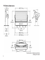
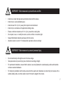
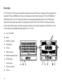
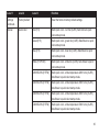
P-5
P-5 WHITE
P-5 TUNABLE WHITE
P-5 Series dimensions
2
All dimensions in milimeters and inches.
Drawing not to scale.
P-5 WASH LIGHT
USER MANUAL REV. 4B
© 2013 SGMTM. Information subject to change without notice. SGM and all affiliated
companies disclaim liability for any injury, damage, direct or indirect loss, consequential
or economic loss or any other loss occasioned by the use of, inability to use or reliance
on the information contained in this manual. The SGM logo, the SGM name and all other
trademarks in this document pertaining to services or products by SGM or its affiliates and
subsidiaries are trademarks owned or licensed by SGM or its affiliates or subsidiaries.
This edition applies to firmware version 1.35 or later.
English edition
3
Contents
Safety information.................................................................................................... 6
Overview.................................................................................................................. 8
Preparing for installation........................................................................................... 9
Installing the P-5..................................................................................................... 10
Connecting AC power............................................................................................. 12
Configuring the device............................................................................................ 13
Setting a static color manually................................................................................ 14
Using stand-alone operation.................................................................................. 15
Connecting to a DMX control device...................................................................... 16
Configuring the device for DMX control ................................................................. 17
Device personality settings..................................................................................... 20
4
Service................................................................................................................... 22
DMX protocols........................................................................................................ 23
Control menu.......................................................................................................... 32
Specifications......................................................................................................... 38
5
Safety information
WARNING! Read the safety precautions in this section before
installing, powering or operating this product.
P-5 series luminaires are intended for professional use only. They are not suitable for household use.
Review the following safety precautions carefully before installing or operating the device.
Preventing electric shock
DANGER! Risk of electric shock. Do not open the device.
•
•
•
•
•
6
Do not open the device; there are no user-serviceable parts inside.
Ensure that power is cut off when wiring the device to the AC mains supply.
Ensure that the device is electrically connected to earth (ground).
Do not apply power if the device or mains cable is in any way damaged.
Do not immerse the fixture in water or liquid.
WARNING! Take measures to prevent burns and fire.
•
•
•
•
•
•
•
•
Install in a location that prevents accidental contact with the device.
Install only in a well-ventilated space.
Install at least 0.3 m (12 in.) away from objects to be illuminated.
Install only in accordance with applicable building codes.
Ensure a minimum clearance of 0.1 m (4 in.) around the cooling fans.
Do not paint, cover, or modify the device, and do not filter or mask the light.
Keep all flammable materials well away from the device.
Allow the device to cool for 15 minutes after operation, before touching it.
WARNING! Take measures to prevent personal injury.
•
•
•
•
Do not look directly at the light source from close range.
Take precautions to prevent injury due to falls when working at height.
For permanent installation, ensure that the device is securely fastened to a load-bearing surface with suitable
corrosion-resistant hardware.
For temporary installation with clamps, ensure that the quarter-turn fasteners are turned fully and secure with a
suitable safety cable, one that is able to bear 10 times the weight of the device.
7
Overview
P-5, P-5 W and P-5 TW luminaires are DMX-controllable, low-profile, IP65-rated, rectangular, LED wash lights. The
standard P-5 offers full RGBW color mixing, color temperature control and incorporate 44 10 W LZ4 RGBW Cool
White Emitter LED’s. The P-5 W (white) is similar, but incorporating white-emitting LEDs. The P-5 TW (tunable
white) offers the ability to adjust white color temperature to 2200, 3000, 4000 or 5300 K. The fixtures all provide
built-in wireless DMX support, stand-alone programs, dimming, and a lamp life expectancy of 50,000 hours. Three
P-5 lens options are available with beam angles of 15°, 21° or 43°.
A
44 x 10 W LEDs
B
Base
C
Safety wire eyelet
D
Cooling fans
E
Tilt lock
F
DMX in and out
G
Wireless antenna socket
H
OLED display
I
Control panel
J
Power connection
K
Tilt lock
8
Preparing for installation
Unpack the device and inspect it to ensure that it has not been damaged in transport.
The P-5 is shipped with two quarter-turn brackets that can be used to mount the device at elevation, and a W-DMXTM
G4 wireless antenna.
The fixture has an ingress protection rating of IP65. This means that it is protected from:
•
•
Dust, to the degree that dust cannot enter the device in sufficient quantities as to interfere with its operation.
Lower pressure jets of water from any direction.
When selecting a location for the device, ensure that it:
•
•
•
Is situated away from public thoroughfares and protected from contact with people.
Not immersed in water or exposed to high-pressure water jets.
Has adequate ventilation.
9
Installing the P-5
The P-5 may be installed in any orientation.
Dimensions in milimeters and inches
For permanent installation on the ground,
remove the rubber feet from the floor
stand/base. Fasten securely through the
resulting holes with four 6 mm (1/4 in.)
corrosion-resistant mechanical fasteners
suitable for the location.
Two quarter-turn brackets are supplied with the device if it is to be flown above the
ground. Remove the floor stand/base and rig the P-5 to a support truss or structure
using the supplied brackets and suitable clamps.
Fasten a safety cable (not shown) between the support
structure and the attachment point on the device. The
safety cable must be able to bear at least 10 times the
weight of the device.
10
WARNING! Always secure an elevated P∙5 with a safety cable as backup
The device can be tilted from -10/+100 degrees. To adjust the tilt angle, loosen the two tilt
screws, one of each side of the fixture, tilt the device to the angle required and retighten the
screws.
If installed horizontally with a downward beam-angle, water can potentially pool in the fan
wells. Under normal operation the moisture will evaporate.
If the device has been operating, always allow it cool for 15 minutes before handling.
11
Connecting AC power
The P-5 can operate on any 208–250 V, 50/60 Hz AC mains power supply. It draws approximately 2 amps at full
power.
For permanent installation, have a qualified electrician wire the mains cable directly to a suitable branch circuit. The
junction’s ingress protection (IP) rating must be suitable for the location.
For temporary installation, the mains cable may be fitted with a grounded 20 A cord cap intended for exterior use.
The device must be grounded/earthed and be able to be isolated from AC power. The AC power supply must
incorporate a fuse or circuit breaker for fault protection.
After connecting the P-5 to power, run the on-board test, using the “Test→Automated test” menu, to ensure that the
device and each LED are functioning correctly. See “Control menu” on page 32.
Do not open the fixture to replace the supplied power cable, or connect the device to an electrical dimmer
system, as this can damage it.
12
Configuring the device
Set up the fixture using the control panel and OLED display at the rear of the fixture.
Navigate the menus and options using the arrow buttons and select items using the
Enter button. The options available are listed in “Control menu” on page 32.
After powering the P-5 on, the display shows the currently selected operating mode
and other information.
A - Operational mode (Quick color, stand-alone or DMX mode)
B - DMX address (if DMX mode is active)
C - External data indicator (if DMX control is active)
D - External data protocol (W-DMX or DMX)
The fixture is set by default to be controlled in DMX mode.
A
6CH MODE
B
C D
8
・DMX
Configuring the device using an Android telephone via RFID
P-5 devices can also be configured wirelessly, via RFID, using the SGM Tool app installed on an Android smart
phone that has NFC support (ISO 15693 and ISO 18000-3 mode 1 compatible, operating on 13.56 MHz ±7k Hz
carrier frequency).
13
Setting a static color manually
The device can be configured to display a predefined and static color (or white, depending on the P-5 model) using
the “Manual→Quick color” menus (see “Control menu” on page 32).
Note that whenever the “Manual→Quick color” settings are changed, the fixture will be set by default to automatically
start in quick color mode whenever it is powered on. This can be reset using the “Settings→Startup mode→Select
startup mode” (see “Control menu” on page 32).
14
Using stand-alone operation
Stand-alone operation is where the fixture is not connected to a control device, but is preprogrammed with a series
of up to 24 scenes that play continuously in a loop. Up to three stand-alone programs can be defined and run from
the menus or one of the programs can be set to run by default whenever the fixture is started.
Each of the three available stand-alone programs contains 24 user-defineable scenes, each scene with its own
RGBW (or white) and shutter settings. Each scene has a defineable fade-in time, for the transition from one color
(or white) to the next, and a wait (static) time, each of up to 999 minutes
and 59 seconds in duration. To program a stand-alone program, use the
“Manual→Editor” menus (see “Control menu” on page 32).
Stand-alone mode at fixture startup is enabled using the
“Settings→Startup mode→Select startup mode→Standalone”
menu. The program to be run is selected using “Settings→Startup
mode→Startup program” menu (see “Control menu” on page 32 for
a description of the menus). The chosen program will run its length
cyclically whenever the fixture is powered on.
A program can be run at any time by selecting it using the
“Manual→Run program” menu.
15
Connecting to a DMX control device
The device is controllable using a DMX control device and it can be connected using either DMX cable or via the
P-5’s built-in wireless W-DMXTM G4 receiver system.
If using a cabled DMX system, connect the DMX in cable (with male 5-pin XLR plug) and out cable (with female
5-pin XLR plug) to the DMX data link. Terminate the DMX out cable of the last device in the data link. For outdoor
installations, use only IP-rated XLR connectors suitable for outdoor use.
Enabling the W-DMX G4 wireless receiver
The W-DMXTM G4 wireless receiver is disabled by default. Ensure that there
is no DMX cable connected to the device. Attach the supplied wireless DMX
antenna to the connector on the back of the device.
Use the “Settings→Wireless DMX→Enable” menu to activate wireless DMX
and the “Settings→Wireless DMX→Wireless LED Status” to confirm that a data
connection has been established. W-DMXTM G4 operates at a frequency of 2.4
GHz, so ensure that the DMX transmitter is configured to operate in this range.
16
Configuring the device for DMX control
About DMX
The P-5 can be controlled using signals sent by a DMX controller on a number of channels (which varies depending
on the DMX mode that has been set. The first channel used to receive data from a DMX control device is known as
the DMX address. Each P-5 must have a DMX address set. For example, if a P-5 has a DMX address of 10 and it
is in 4-channel DMX mode, then it uses channels 10, 11, 12 and 13. The following fixture in the DMX chain could
then be set to a DMX address of 14. If two or more DMX devices of the same type have the same DMX address,
then they will mimic each other’s behavior. Incorrect settings will result in unpredictable responses to the lighting
controller.
Setting the DMX address
The DMX address can be seen at the top of the menu structure. To
change the address setting, press the up arrow to increase the address,
or the down arrow to decrease the setting. When the desired address
is displayed, press Enter to save the setting. For your convenience, the
suggested DMX address of the next fixture is displayed to the right. Note
that channel spacing is determined by the DMX mode.
SET DMX ADR
10
NEXT FIX
13
See the “DMX protocols” on page 23 for specific DMX control values.
17
Setting the DMX mode
Using the “DMX mode” menu available from the control panel, specify the DMX mode that provides the device
controls that you require:
P-5 DMX modes
Function
3
Individual control of color channels for red, green & blue. White is automatically mixed in.
4
Individual control of color channels for red, green, blue and white (RGBW).
6
RGBW, dimmer, shutter, strobe, pulse & open shutter effects.
8
RGBW with fine control of individual colors.
9
Dimmer and RGBW, with fine control of individual colors.
10
Dimmer and RGBW, with fine control.
P-5 TW DMX modes
18
Function
2
Dimmer & white temperature control (2200K-5300K).
4
White temperature control - 2200K, 3000K, 4000K and 5300K.
6
Dimmer, white temperature control (2200K, 3000K, 4000K and 5300K), shutter, strobe,
pulse & open shutter effects.
8
Fine and coarse control of white temperatures (2200K, 3000K, 4000K and 5300K)
P-5 W DMX modes
Function
1
Dimmer.
2
Dimmer, shutter, strobe, pulse & open shutter effects.
2 (16-bit)
Fine and coarse dimmer.
19
Device personality settings
Setting the dimming curve
The dimming curve is the degree of fineness in control available at low light levels, linear or gamma corrected. Linear
control provides uniform adjustment throughout the control action, whereas gamma corrected dimming provides finer
control at low light levels, where the eye is more sensitive to change. By default, the P-5 uses gamma corrected
dimming. For uniform response, set all devices to the same dimming curve. To set the desired dimming curve, use the
“Settings→Dimming curve” menu.
Flipping the OLED display
If the device is installed hanging upside down, it might be a useful to flip the screen so that it is easy to read. To flip the
display, use the “Settings→Flip display” menu, or press the up and down buttons on the control panel at the same time.
Setting the OLED display saver
By default the OLED display turns off after a short period when the control panel is not in use, but it can be set so that
it dims. Pressing any key will always turns on the display or restore it to normal brightness. To enable the display saver,
use the “Settings→Display saver” menu.
20
Setting the fan mode
For operating environments where low-noise is a requirement or where the fixture will be operating in high
temperatures, it is possible to adjust the default fan speed to low or high using the “Settings→Fan mode” menu.
21
Service
There are no user-serviceable components in the device. Do not open the P∙5, as doing so is likely to damage its
ingress protection. Consult your SGM dealer if the device operates abnormally, is defective or otherwise in need of
service or repair.
Upgrading the firmware
The firmware installed on the fixture can be identified using the “Info→Firmware version” menu. We recommend that
you keep your device’s firmware current. Visit http://www.sgmsupport.com to obtain the most up-to-date firmware. To
perform firmware updates, you need a Windows personal computer and an SGM USB 5-Pin-XLR upload cable (available from your SGM distributor: P/N 40500201).
Cleaning
To obtain optimal performance, regular cleaning is essential. Cleaning schedules will vary greatly depending on the
operating environment, and the installation should therefore be checked at frequent intervals within the first few weeks
of operation to see whether cleaning is necessary. This procedure will allow you to assess cleaning requirements
in your particular situation. If in doubt, consult your SGM dealer for a suitable maintenance schedule. Clean the P∙5
using a soft cloth dampened with a solution of water and a mild detergent. Do not use products that contain solvents,
abrasives or caustic agents for cleaning, as they can cause damage to both hardware, cables and connectors.
22
DMX protocols
Configuring DMX is described in “Setting the DMX mode” on page 18. This section contains “P-5 DMX protocols” (below), “P-5 W DMX protocols” on page 28, and “P-5 TW DMX protocols” on page 29.
P-5 DMX protocols
P-5 - 3 channel mode - RGB plus auto white
Channel
Value
Percent
Function
1
0-255
0-100
Red 0-100%
2
0-255
0-100
Green 0-100%
3
0-255
0-100
Blue 0-100%
P-5 - 4 channel mode - RGBW
Channel
Value
Percent
Function
1
0-255
0-100
Red 0-100%
2
0-255
0-100
Green 0-100%
3
0-255
0-100
Blue 0-100%
4
0-255
0-100
White 0-100%
23
P-5 - 6 channel mode - RGBW plus effects
Channel
Value
Percent
0-7
0-2
Shutter Blackout
8-15
3-6
Shutter Open
16-151
7-58
Variable Strobe
152-175
59-68
Pulse Open
176-199
69-78
Pulse Close
200-244
79-95
Variable Random Strobe
245-255
96-100
Shutter Open
2
0-255
0-100
Dimmer 0-100%
3
0-255
0-100
Red 0-100%
4
0-255
0-100
Green 0-100%
5
0-255
0-100
Blue 0-100%
6
0-255
0-100
White 0-100%
1
24
Function
P-5 - 8 channel mode (16-Bit) - RGBW plus fine
Channel
Value
Percent
Function
1
0-255
0-100
Red 0-100% (MSB)
2
0-255
0-100
Red Fine (LSB)
3
0-255
0-100
Green 0-100% (MSB)
4
0-255
0-100
Green Fine (LSB)
5
0-255
0-100
Blue 0-100% (MSB)
6
0-255
0-100
Blue Fine (LSB)
7
0-255
0-100
White 0-100% (MSB)
8
0-255
0-100
White Fine (LSB)
25
P-5 - 9 channel mode (16-Bit) - Dimmer & RGBW plus fine
Channel
Value
Percent
1
0-255
0-100
Dimmer 0-100%
2
0-255
0-100
Red 0-100% (MSB)
3
0-255
0-100
Red Fine (LSB)
4
0-255
0-100
Green 0-100% (MSB)
5
0-255
0-100
Green Fine (LSB)
6
0-255
0-100
Blue 0-100% (MSB)
7
0-255
0-100
Blue Fine (LSB)
8
0-255
0-100
White 0-100% (MSB)
9
0-255
0-100
White Fine (LSB)
26
Function
P-5 - 10 channel mode (16-Bit) - RGBW plus fine
Channel
Value
Percent
Function
1
0-255
0-100
Dimmer 0-100% (MSB)
2
0-255
0-100
Dimmer Fine (LSB)
3
0-255
0-100
Red 0-100% (MSB)
4
0-255
0-100
Red Fine (LSB)
5
0-255
0-100
Green 0-100% (MSB)
6
0-255
0-100
Green Fine (LSB)
7
0-255
0-100
Blue 0-100% (MSB)
8
0-255
0-100
Blue Fine (LSB)
9
0-255
0-100
White 0-100% (MSB)
10
0-255
0-100
White Fine (LSB)
27
P-5 W DMX protocols
P-5W - 1 channel mode - Dimmer
Channel
Value
Percent
1
0-255
0-100
Function
Dimmer 0-100%
P-5W - 2 channel mode - Strobe & dimmer
Channel
1
2
28
Value
Percent
Function
0-7
0-3
Shutter Blackout
8-15
4-5
Shutter Open
16-151
6-59
Variable Strobe
152-175
60-69
Variable Pulse Open
176-199
70-78
Variable Pulse Close
200-244
79-96
Variable Random Strobe
245-255
97-100
Shutter Open
0-255
0-100
Dimmer 0-100%
P-5W - 2-channel mode (16-bit) - Fine & coarse dimmer
Channel
Value
Percent
Function
1
0-255
0-100
Dimmer 0-100% (MSB)
2
0-255
0-100
Fine dimmer (LSB)
P-5 TW DMX protocols
P-5TW - 2-channel mode - Dimmer/CTC
Channel
Value
Percent
Function
1
0-255
0-100
Dimmer 0-100%
2
0-255
0-100
CTC 0-100% 2200K-5300K
29
P-5TW - 4-channel mode - Tunable white
Channel
Value
Percent
1
0-255
0-100
Function
White 2200K 0-100%
2
0-255
0-100
White 3000K 0-100%
3
0-255
0-100
White 4000K 0-100%
4
0-255
0-100
White 5300K 0-100%
P-5TW - 6 channel mode - Strobe, dimmer & tunable white
Channel
1
30
Value
Percent
Function
0-7
0-3
Shutter Blackout
8-15
4-5
Shutter Open
16-151
6-59
Variable Strobe
152-175
60-69
Variable Pulse Open
176-199
70-78
Variable Pulse Close
200-244
79-96
Variable Random Strobe
245-255
97-100
Shutter Open
2
0-255
0-100
Dimmer 0-100%
3
0-255
0-100
White 2200K 0-100%
4
0-255
0-100
White 3000K 0-100%
5
0-255
0-100
White 4000K 0-100%
6
0-255
0-100
White 5300K 0-100%
P-5TW - 8-channel mode - Tunable white, coarse & fine
Channel
Value
Percent
Function
1
0-255
0-100
White 2200K 0-100%
2
0-255
0-100
White 2200K fine
3
0-255
0-100
White 3000K 0-100%
4
0-255
0-100
White 3000K fine
5
0-255
0-100
White 4000K 0-100%
6
0-255
0-100
White 4000K fine
7
0-255
0-100
White 5300K 0-100%
8
0-255
0-100
White 5000K fine
31
Control menu
Level 1
Level 2
Level 3
Function
DMX Mode
x Channel Mode
-
Selects DMX mode. See “Setting the DMX mode” on page
18 for information about the features of each mode.
Info
Product type
-
Displays the fixture product type.
Firmware Version
-
Displays installed software version number.
Serial number
-
Displays the fixture serial number.
RDM ID
-
Displays the fixture RDM ID (for use with the SGM Tool app)
DMX View
-
Displays received DMX levels.
Temperatures
Mainboard
Displays temperature on main circuit board.
32
LED Panel
Displays temperature on LED display panel.
Log
-
Displays recorded operating data and error codes.
Debug
-
Service use only.
Level 1
Level 2
Level 3
Function
Settings
Wireless DMX
Log Off
Sends log off command to W-DMXTM system.
Wireless LED status
Blinking - not connected to data
Solid - connected to data
Enable
Enables wireless DMX operation.
Disable
Disables wireless DMX operation.
Select startup mode
Default operating mode when the fixture is powered on:
1. Quick color
2. Stand-alone
3. DMX (factory default)
Startup program
Stand-alone program 1, 2 or 3. Only used if the startup
mode is set to “stand-alone”. 1 is the default.
Linear
Provides equal resolution dimming from 0 to 100%.
Gamma
Corrected
Provides high resolution dimming at low levels.
Disable
Selects normal control panel display.
Enable
Flips control panel display.
Startup mode
Dimming Curve
Flip Display
33
Level 1
Level 2
Level 3
Function
Settings
continued...
Display Saver
Screen Dim
Dims the OLED display, when the control panel is not in use
Screen Off
Turns off OLED display, when the control panel is not in use.
Standard
Adjust fan speed relative to fixture internal temperature.
Silent
Low fan speed for quiet operation.
Max power
High fan speed for maximum cooling effect.
Min. red (P-5)
Adjust default minimum setting (0-1000).
Fan mode
Minimum values
Min. green (P-5)
Min. blue (P-5)
Min. white (P-5)
Min. line 1 (P-5W)
Min. line 2 (P-5W)
Min. line 3 (P-5W)
Min. line 4 (P-5W)
Min. 2200 K (P-5TW)
Min. 3000 K (P-5TW)
Min. 4000 K (P-5TW)
Min. 5300 K (P-5TW)
34
.
Level 1
Level 2
Level 3
Function
Settings
continued...
Factory default
-
Reset the fixture to factory default settings.
Manual
Quick color
Red (P-5)
Static quick color - red mix (0-255). Sets fixture to quick
color startup mode.
Green (P-5)
Static quick color - green mix (0-255). Sets fixture to quick
color startup mode.
Blue (P-5)
Static quick color - blue mix (0-255). Sets fixture to quick
color startup mode.
White (P-5/P-5W)
Static quick color - white mix (0-255). Sets fixture to quick
color startup mode.
2200 KELVIN (P-5TW)
Static quick color - white temperature 2200 K mix (0-255).
Sets fixture to quick color startup mode.
3000 KELVIN (P-5TW)
Static quick color - white temperature 3000 K mix (0-255).
Sets fixture to quick color startup mode.
4000 KELVIN (P-5TW)
Static quick color - white temperature 4000 K mix (0-255).
Sets fixture to quick color startup mode.
5300 KELVIN (P-5TW)
Static quick color - white temperature 5300 K mix (0-255).
Sets fixture to quick color startup mode.
35
Level 1
Level 2
Level 3
Function
Manual
continued...
Run program
1, 2 or 3
Run one of the three user programs.
Stop program
-
Stop running program.
Editor
Program
Currently selected program (1, 2 or 3).
Scene
Currently selected scene (1-24).
Red (P-5)
Red value in currently selected scene (0-255).
Green (P-5)
Green value in currently selected scene (0-255).
Blue (P-5)
Blue value in currently selected scene (0-255).
White (P-5/P-5W)
White value in currently selected scene (0-255).
2200 KELVIN (P-5TW)
2200 K white temperature value in currently selected scene
(0-255).
3000 KELVIN (P-5TW)
3000 K white temperature value in currently selected scene
(0-255).
4000 KELVIN (P-5TW)
4000 K white temperature value in currently selected scene
(0-255).
5300 KELVIN (P-5TW)
5300 K white temperature value in currently selected scene
(0-255).
36
Level 1
Level 2
Level 3
Function
Manual
continued...
Editor
continued...
Shutter
Shutter setting in currently selected scene (0-255):
Test
0-7
Shutter Blackout
8-15
Shutter Open
16-151
Variable Strobe
152-175
Pulse Open
176-199
Pulse Close
200-244
Variable Random Strobe
245-255
Shutter Open
Fade time min.
Fade-in (transition) time to current scene in minutes (0-999).
Fade time sec.
Fade-in (transition) time to current scene in seconds (0-59).
Wait time min.
Wait (static) time in current scene in minutes (0-999).
Wait time sec.
Wait (static) time in current scene in seconds (0-59).
Off
-
Stops test sequence execution.
Automated Test
-
Initiates a self-test sequence.
Burn In Test 30
min
-
Service use only.
Display test
-
Service use only.
37
Specifications
PHYSICAL
Length x width x height................................................................................ 497 x 185 x 300 mm (19.6 x 7.3 x 11.8 in.)
Weight ................................................................................................................................................ 8.9 kg (19.6 lbs.)
LIGHT SOURCE AND OPTICS
Illumination source.....................................................................................................................44 x 10 W power LEDs
Expected lifetime....................................................................................................................................... 50,000 hours
Luminous flux......................................................................................................................................... 25,800 lumens
Spread angle............................................................................................................... 15°, 21° or 43° lenses available
White temperatures (P-5TW)................................................................................2200 K, 3000 K, 4000 K and 5300 K
CONSTRUCTION
Housing ........................................................................................................................................................ Aluminium
Finish ................................................................................................................................ Electrostatic powder coating
INSTALLATION
Orientation................................................................................................................................................................ Any
Minimum distance between units .............................................................. Horizontal: 0 mm, Vertical: 40 mm (1.6 in.)
38
OPERATING CONDITIONS
Ambient temperature range (Ta)....................................................................................... -10° to 40° C (14° to 104° F)
Maximum relative humidity ..................................................................................................................................... 98%
IP rating ................................................................................................................................................................. IP 65
PROGRAMMING AND CONTROL
Control interface .............................................................. USITT DMX 512-A (serial cable) or W-DMXTM G4 (wireless)
DMX channel requirements .................................................................................. 3 to 10 channels (mode dependent)
Local control ............................................................................................. 5 button panel with OLED graphical display
Software update .................................................................. via Windows PC and SGM USB 5-Pin-XLR upload cable
CONNECTIONS
AC power input.................................. 1.6# (15 AWG) mains cable prepared for direct tie-in or user-supplied cord cap
DMX data input ............................................................................................................ Neutrik locking 5-pin XLR male
Driver data output ..................................................................................................... Neutrik locking 5-pin XLR female
ELECTRICAL
AC power ...................................................................................................................................... 208–250V, 50/60 Hz
Maximum power consumption (all LEDs on)....................................................................................................... 410 W
Standby power consumption (all LEDs off) ............................................................................................................ 8 W
39
TYPICAL POWER AND CURRENT
208 V, 60 Hz.................................................................................................................................405 W, 1.9 A, 0.99 PF
230 V, 50 Hz ..............................................................................................................................405 W, 1.7 A, 0.988 PF
240 V, 50 Hz...............................................................................................................................405 W, 1.6 A, 0.988 PF
240 V, 50 Hz.............................................................................................................................405 W, 1.55 A, 0.988 PF
Peak inrush current..................................................................................................................................................14 A
PF power factor is measured at full load with all LEDs 100% driven.
FUSES
Main fuse (not user-replaceable).............................................................................................................................. T5A
ACCESSORIES
SGM USB 5-Pin-XLR upload cable..........................................................................................................P/N 40500201
* Specifications subject to change without notice
40
41
42
43