1
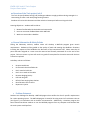
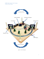
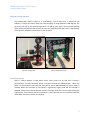
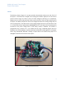
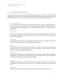
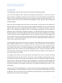
ENGR 1181 | Lab 8: Train Project
-
Project Description
-
Lab Procedure 8A
-
Lab Procedure 8B/8C
-
Notebook Guidelines
1
ENGR 1181 Lab 8: Train Project
Project Description
Project Description
2
ENGR 1181 Lab 8: Train Project
Project Description
• Overview of the Train project, Lab 8
The Train Project (Problem Solving Lab) challenges students to apply problem-solving strategies in a
team setting to solve a real-world programming scenario.
Students will review this document and then take the Carmen quiz before arriving to the lab.
Learning Objectives – students will be able to:
1. Become familiarized with the Arduino microcontroller
2. Learn to use sensor feedback data within MATLAB.
3. Work as a team under a deadline.
• General Information & Safety Policies
During the laboratory sessions, student teams will develop a MATLAB program given certain
requirements. Students will be graded on the quality of work and meeting the deadlines. Situations
involving late reports will be handled at the discretion of the instructional staff. Please note that all
parts and tools assigned to a team must be returned and formally accounted for at the end of the
project. Failure to return any item will result in a grade of incomplete for the entire team until the item
is found or replaced.
Lab safety rules are as follows:
•
•
•
•
•
•
•
•
•
No open toed shoes
Do not touch the electrified track
Don't stand on lab chairs
Don't sit or stand on lab tables
Remove dangling jewelry
Pull back long hair
Refrain from wearing loose clothes
Recall location of first-aid kit
Report ALL injuries
• Problem Statement
Students are challenged to develop a MATLAB program that satisfies the client’s specific requirements
for a train operating system. The MATLAB program is tested in lab using control of a miniature train set
(see Figure 1) via interaction with an Arduino microcontroller. Additionally, a simulator program has
been created that allows students to run the MATLAB program from any computer and simulate how
the train system would perform.
3
ENGR 1181 Lab 8: Train Project
Project Description
Introduction and Background
Your team is a group of computer and mechanical engineers working for a software engineering firm.
Your company has requested that you develop a software package that will control an automated
railroad transportation system. This software will be sold to different cities with different traffic
regulations such as urban and rural communities, so the program must be robust to easily be adjusted
to different situations.
The software should control:
• Train movement (speed variation or stoppage at stations).
• Road - railroad crossing gate.
• All railroad signals and lightings.
A safe train crossing must have flashing warning lights (and optional sounds) that signal drivers and
pedestrians when a train is approaching. It must also have a crossing gate that lowers before a train
arrives to prevent cars from driving onto the tracks. For further safety, the train will be signaled to slow
down when approaching the crossing. Once the train has fully cleared the crossing, it may resume a
higher velocity. This entire process will be computer programmed for repeated use.
Figure 1 : N-Scale Model Train Set
In rural (small town) communities, the roadway traffic will be moving at faster speeds. This is due to
open terrain and being less densely populated. In the urban (dense city) settings, the roadway traffic
will be moving more slowly due to increased traffic flow, pedestrians, and safety for increased
population density. Your program must be developed such that it can easily be adjusted in the future
based on various clients’ needs. Cities in rural settings will require more warning time between the
flashing lights and the gate moving down, as the cars will be moving faster (i.e. 45-55 mph). Faster
traveling traffic needs more time to stop (and distance on roadway) prior to the gate coming down.
Likewise, cities in the urban setting (25-35 mph) require less warning time between the lights flashing
4
ENGR 1181 Lab 8: Train Project
Project Description
and the gate moving down. However, one must also be aware of excessive time for cars to be stopped
as traffic will back-up unnecessarily if the warning lights and gate movement occur too soon. Balancing
these timing considerations is important.
The test track, shown in Figure 1, will be used to simulate a train running in a real world environment.
After completing the code, you will write documentation that can explain your program to a developer
as well as a customer. Your company also must be clear on any issues and problems resolved
throughout development, as well as recommendations for future trials and program improvements.
Your task will be completed using the MATLAB coding software. You will write a program that will fully
automate the crossing gate sequence and control the train’s velocity. This will be accomplished by
monitoring via two break beam sensors to determine the train’s location. The train motor speed, the
crossing gate, and the warning lights can then be adjusted accordingly. These changes are made by
sending commands to the Arduino microcontroller, which can be controlled through your MATLAB
program.
• Description of Components
Train/Tracks
The track and train are a standard n-scale model train set, shown in Figure 2. N-scale is 1/160 of
the real train’s size. This scale is widely used as it allows for complex railroad designs in a small
space. The track provided has a width of 9mm between rails, which are made of metal for
conductivity. Powering the train can be accomplished by running a current along the track. The
Arduino is connected to the track, and can provide roughly 11.2 volts to power the train’s DC
motor. The speed of the train will vary with the amount of voltage provided and the direction
depends on the polarity. See Figure 3 on the following page for a fully described layout of the
train track.
5
ENGR 1181 Lab 8: Train Project
Project Description
Figure 2 : N-scale Train Locomotive
6
ENGR 1181 Lab 8: Train Project
Project Description
Direction of Train
Vehicle Roadway
Crossing Gate & Lights
Train Station
Approach Gate
Departure Gate
Power Supply
Direction of Train
Figure 3 : Train Track Layout
7
ENGR 1181 Lab 8: Train Project
Project Description
Railroad Crossing and Gate
The railroad gate, shown in Figure 4, is controlled by a servo motor that is attached to the
Arduino. To control the motor, teams will need to specify an angle between 0-180 degrees. The
servo arm will stay at the specified angle until it is told to move again. At the railroad crossing
there will be two red LEDs that will flash to warn cars and pedestrians that a train is approaching.
These LEDs are attached to the Arduino in pins 14 and 15.
Figure 4 : Crossing Gate
Figure 5 : Break Beam Sensor
Break Beam Sensors
Figure 5 (above) depicts a break beam sensor. Each sensor has an LED that is facing a
photoreceptor. The LED constantly shoots a red beam towards the photoreceptor. While this
beam is uninterrupted, a low numerical value will be sent to MATLAB when the sensor status is
checked. When the red beam is interrupted, a significantly higher value will be returned to
MATLAB. Teams will use the break beam sensors to monitor when the train has reached the gate
crossing area. These sensors connect to analog pins 2 and 3 and will receive a numerical value that
differs when the beam is broken or unbroken.
8
ENGR 1181 Lab 8: Train Project
Project Description
Arduino
The Arduino, shown in Figure 6, is an open-sourced microcontroller and serves as the “brain” of
the project. The Arduino has 12 digital and 6 analog pins available. Digital pins can be used as
inputs to sense a high (>2.5 volts) or low (<2.5 volts) voltage by returning 1 or 0 respectively.
Digitals pins can also be used to provide a low current (<40 ma) 5 volts to a device when used as
an output. The Arduino samples the value of the voltage and converts the analog voltage value to
a binary voltage value. The Arduino uses a 10 bit analog to digital converters to do the above. That
is, a 0 Volt input will be represented as 0000000000 and a 5 Volt input will be represented as
1111111111. Every other voltage value is some binary number in between. The Arduino is
programmed using a subset of C++, but students will be using a MATLAB program that uses
keywords, such as motorSpeed, to execute commonly used Arduino code segments. For example,
when using motorSpeed, MATLAB is sending a simple code to the Arduino that jumps to an
analogWrite statement that controls motor speed.
Figure 6 : Arduino Microcontroller
9
ENGR 1181 Lab 8: Train Project
Project Description
• Arduino/MATLAB commands
Below are descriptions of each of the Arduino commands necessary for this project. These are MATLAB
commands that are used to control the Arduino, and ultimately the train set. Keep in mind that this page
does not include proper syntax. The use and syntax of these commands will be explained in Lab 8A.
a=arduino(‘COM#’)
This command will connect the Arduino to MATLAB. The COM port number may change based on
a team’s work station; instructions in Lab 8A will explain how to find the COM port number.
Teams will replace the # with a digit such as 3. The port will never be 1; port 1 is a physical port on
the computer.
servoAttach
This command is needed only once per session (if entered via command window) or once per mfile (if writing a program). The command will establish a connection to the servo motor that
controls the crossing gate.
servoWrite
This command is used to move the crossing gate. The usable range of this command is between 10
and 170; values outside of this range can damage the servo motor.
motorRun
This command is used to control the direction of the train’s velocity. The direction can be forward,
backward, or the train can be stopped. It can be used repeatedly; however the train’s direction
does not need to be changed during this scenario.
motorSpeed
This command is used to control the speed of the train. The usable values allowed are 0 (stopped)
and between 170 and 255; values outside of this range can damage the motor. This command will
be used whenever the train’s speed needs to be changed.
pinMode
This command is used to set up a connection to the LED crossing lights. It must be issued once per
individual LED. The necessary information to use this command is the digital pin number of each
LED.
digitalWrite
This command will be used to change the status of the LEDs, either on or off (logical 1 or 0).
10
ENGR 1181 Lab 8: Train Project
Project Description
analogRead
This command will be used to gather information from the break beam sensors. Lab 8A procedure
and data will allow users to interpret and apply their use. The Arduino must be ‘warmed up’
before taking a sensor reading and the first few readings taken from the sensor are not reliable!
For this reason students must call analogRead twice before taking an official sensor reading. For
example:
a.analogRead(approach);
a.analogRead(approach);
if
a.analogRead(approach)>250
...
tic
This is MATLAB’s time function. Think of tic as a stopwatch; when this command is issued, the
time starts. The “stopwatch” will continue on forever until tic is used again, resetting the time to
0.
toc
This command is used with tic. After tic has been used, entering toc will return the amount of time
that has passed since tic started in seconds. Use the MATLAB help file or an online search engine
to learn more about tic and toc. Note that the returned time will always contain a long trail of
decimals and will never be equal to an exact time value such as 2 seconds. This is because
MATLAB does not increment time in a predictable manner like a stopwatch.
delete(instrfindall)
This command can be used to clear out any COM port assignments in MATLAB. Teams should have
this command at the top of any script file before attaching the Arduino. It can be useful if errors
are encountered when attaching the Arduino.
Note: The ‘pause’ function is not allowed for this project. This is a MATLAB function that
halts a program for a specified amount of time. This program requires constant data
monitoring, therefor any pause should NOT be used in this application, or any application
that requires data monitoring. This is a safety concern if your train is operating and stops
monitoring as valuable seconds lost in the information loop can cost a human life.
11
ENGR 1181 Lab 8: Train Project
Project Description
• Using the Train Set Simulator
Students may work on the train project from home or in a computer lab by setting up the train set
simulator, in conjunction with MATLAB. The simulator emulates the physical train set in a small window
on the desktop. Code that is working on the simulator will also work on the lab train set, and vice versa
with a minor change to the code. The simulator depicts the train movement and location, the train
speed, the break beam sensors, the crossing gate, the flashing crossing lights, and it differentiates
between the approach and departure sides of the track. The train set simulator ZIP file can be
downloaded from the EEIC course website under Lab 8A, Lab 8B, or Lab 8C. After downloading the ZIP
file, open up the file named ‘Train Simulator Student User Manual.docx’. This word document will
provide further instructions on how to setup the simulator. Figure 7 shows a train simulator in action. It
is highly reccomended that every student learns how to use the simulator.
Figure 7 : Train Simulator
12
ENGR 1181 Lab 8: Train Project
Project Description
• Project Timeline
Lab 8A
The goals of Lab 8A are to become familiar with the Arduino/MATLAB interface as well as the necessary
commands used when programming your train. It is recommended to use the TeamViewer software so
that both sides of your work station can view and/or participate in the programming aspect of the lab
(you can find it in EEIC website).
Lab 8A Breakdown:
•
•
•
•
•
•
•
In-lab introduction
Determine which ports do what specific tasks
Complete exercise with commands
Learn MATLAB command lines
Mini problem solving scenario
Pseudocode development
Lab clean-up
Due at the end of lab 8A:
Train Project Worksheet for Tasks 1-7
Lab 8B
Students begin the train project problem solving lab program. Students will start using the Train
Simulator as an additional tool to troubleshoot MATLAB code outside of lab. Teams should begin
compiling the information needed for the Project Documentation Package.
Due at the beginning of lab 8B:
1. Carmen Quiz [Individual assignment]
2. Pseudocode [Team assignment]
Lab 8B Breakdown:
•
•
•
In-Lab Introduction
Problem Solving Session
Lab clean-up
13
ENGR 1181 Lab 8: Train Project
Project Description
Lab 8C
Students have 40 minutes to finalize the train project problem solving code assignment. This time may
also be used to work on the extra credit assignments (see EEIC website for details). Each team is
expected to have a working code by the end of the 40 minutes. It is highly recommended that each
team have a complete code that works on the train simulator before coming to this lab. After the 40minute problem solving session, the instructional staff will test each group’s program individually. After
this, each team must complete the Project Documentation Notebook to be turned in by the last day of
the university’s scheduled classes (before the reading day).
Lab 8C Breakdown:
•
•
•
•
In-Lab Introduction
Problem Solving Session
Testing Session
Lab clean-up
Due at the end of lab C:
1. Teams must have their Final Testing Checklist evaluated by a TA before the end of lab 8C.
14
ENGR 1181 Lab 8: Train Project
Lab Procedure 8A
Week 1
Lab Procedure 8A
15
ENGR 1181 Lab 8: Train Project
Lab Procedure 8A
Lab 8A
Preparing the Lab Station
The following tasks must be completed before beginning Task 1 of the lab procedure:
1. Plug the Power Supply into the outlet/power strip.
2. Ensure that the power strip is turned on.
3. Ensure the black power cord is plugged into the red and black power cable coming out of the
side of the train set. Note: Do not plug this directly into the Arduino.
4. Plug the Arduino USB cord into the computer.
5. Download the zip file for the MATLAB train simulator from Lab 8A on the EEIC website and save
it to your desktop.
6. Right click the zip file and select extract all.
7. A new folder named MATLAB_Train_Simulator will be created. This folder will be your
workspace for this project.
8. Ensure that the red LEDs on the Break beam sensors are on. Ensure that the yellow LEDs on the
Arduino are on as well. This means that these devices have power.
9. Open MATLAB.
10. Open the ‘Train Project Lab Worksheet’ in Excel.
Task 1: Connecting to the Arduino
1. Open the Windows Device Manager. To open the Windows Device Manager, click on the start
menu, then in the search box type ‘device manager’ and press the enter key. You will receive an
error message, click OK.
2. Once the Device Manager has opened, click on the arrow next to Ports (COM & LPT). Once the
Arduino has finished installing, look for Arduino UNO (COM#) in the list. Your number COM# will
be shown here.
3. Write this number in the Train_Project_Lab_Worksheet under Task 1.
4. In MATLAB, find the change folder icon, which is located toward the left side of the screen,
just above the words “Current Folder”.
5. Click change folder, and find the MATLAB_Train_Simulator folder. Select it and click change
folder. This tells MATLAB to work out of the train simulator folder.
6. In MATLAB’s command window, clear all variables and clear the command window using clear
all, close all, and clc.
7. Enter the command delete(instrfindall). This will clear any previous arduino connections.
8. In the MATLAB command window, type: a=arduino(‘COM#’) where # is the COM port
number found earlier. For example, if your Arduino is in COM3, type: a=arduino(‘COM3’).
- Do NOT type the ‘arduino’ command without assigning it to the variable ‘a’ using the
equals sign. If you do, use the clear commands issued above in Steps 4 and 5. Do not
copy and paste the command, type it in manually. MATLAB does not correctly interpret
all Word formatting.
9. MATLAB will attempt a connection with the Arduino.
10. If an error message pops up, double check that you have followed the above steps exactly as
listed, repeating steps as necessary. If you try again and get the same message, ask a member of
the instructional staff for assistance.
16
ENGR 1181 Lab 8: Train Project
Lab Procedure 8A
11. Examine the command window output. Notice how Servos are Detached and Digital Pins are
Unassigned. If you do not see the output, repeat the command without suppressing the output
with a semi-colon.
12. If the connection is successful, a message will display “FE Train Shield Script File detected!” 11.
Clear the command window with clc.
Task 2: Connecting to the Servo
1. Your servo (crossing gate) should be in servo port 1.
2. To attach the servo and the Arduino, the command a.servoAttach(1) is used, where 1 is the
servo number. This command must be issued every time the arduino is reconnected.
3. When using any Arduino command, the letter ‘a’ with a period will come before the command.
This is needed since we defined a=arduino(‘COM3’). For example, to attach the servo, you must
type a.servoAttach(1). Type the command in the MATLAB command window now. Be sure to
use your servo number and proper capitalization where necessary.
4. To check your servo, type the command a.servoStatus. Servo 1 should now be attached.
5. To control the servo, the command a.servoWrite(X,θ) is used. X is the servo number (1) and θ is
the angle.
- IMPORTANT: For θ, a value between 10 and 170 should be used. Using a value outside
of this range can damage the servo motor.
6. Enter the command a.servoWrite(X,θ) where X is 1 and θ is 170. The gate should now be closed.
7. Now determine at which value θ the gate is vertical. Write your answer in the worksheet.
Task 3: Setting up the LEDs
1. In order to use the LEDs, they must first be assigned to the Arduino. The LEDs on the crossing
light are attached to digital pins 14 and 15.
2. First issue the command a.pinMode(X,‘output’) where X is 14 and then 15. The command must
be issued twice, once for each pin assignment.
3. Now that the LEDs are attached, their status can be changed through the Arduino. To change
the status of the digital pin, enter the command a.digitalWrite(15,1). One of the LEDs should
now be on. Which LED is on? Write your answer in the worksheet.
4. The LED changes with a logical value of 0 or 1. Logical 0 turns the LED off, and logical 1 turns
the LED on. Using the command line, turn on both LEDs.
5. When using the digitalWrite command, it is advisable to assign the pin value to a variable to
keep track of which pins are assigned to the left and right LEDs. To do this, assign the variable
rLED=14 and use rLED in the digitalWrite command in place of ‘14’. The new command will look
like this: a.digitalWrite(rLED,1). The same process can be used for the left LED.
17
ENGR 1181 Lab 8: Train Project
Lab Procedure 8A
Task 4: Making the Train Move
1. Place the train on the track at the location where the black piece of track has wires connected to
it from the Arduino. Ensure that all wheels are properly on the track, check with your
Instructional Staff if necessary.
2. The train has three states of motion: forward, backward, and release. Release is a command
that can be used to stop the train. To enable the train to move forward, type the command
a.motorRun(1,‘forward’). The train won’t move until you issue the motorSpeed command in the
next step.
3. Now, to set the train speed, use the command a.motorSpeed(1,X), where X is a value from 0 to
255 as described in the next step.
- IMPORTANT: For X, the train will not run if not given ample power, therefore a useable
range is about 170-255. If you set the train to move and you hear the motor whirring
but there is no movement, immediately pull the train off the track, set the motorSpeed
to 0, and then try again with a larger value.
4. Use the command to set the motor speed to 255. The train should now be moving at its max
speed. To stop the train, change the speed command by entering a.motorSpeed(1,0) or set the
motorRun to ‘release’ by typing a.motorRun(1,‘release’).
Task 5: Setting up the Break Beam Sensors
1. Unlike the servo and LEDs, the break beam sensors do not need initial setup. The two sensors
will be known as ‘approach’ and ‘departure’. Analog port 2 is connected to the approach sensor
and analog port 3 is connected to the departure sensor.
2. For clarity, create the variables approach=2 and departure=3. This helps keep track of the ports.
3. When the arduino communicates with the break beam sensors, a numerical value is returned to
MATLAB. By testing the sensor under difference settings, the meaning of the value returned to
MATLAB can be interpreted.
4. To receive the current status of the break beam sensor, enter the command
a.analogRead(approach), where approach=2. The command window will display a value. Enter
that value into the worksheet. This is the value of the unobstructed sensor. Repeat the
command at least 5 times. Enter 2 more values into the worksheet.
5. Have a group member block the approach beam with his or her fingers. While blocked, a green
LED on the sensor circuit board will light up, verify this.
6. Once again, type a.analogRead(approach) several times. Enter that value into the worksheet.
This is the value of the obstructed sensor. Enter 2 more values into the worksheet, and answer
the following questions:
- Does there appear to be a pattern to the values?
- How do these values differ from the unobstructed values?
- Are the values always consistent? Why might this be important when it comes to
writing a program?
18
ENGR 1181 Lab 8: Train Project
Lab Procedure 8A
7. Very Important! When using the analogRead command within a script-file, you must call
analogRead multiple times before testing the returned value. For example:
a.analogRead(approach);
a.analogRead(approach);
if
a.analogRead(approach)>250
...
The reason for this is that the sensors must be activated a few times before they can reliably
take a reading. This means that you must take multiple “dummy reads” before taking a reading
to be evaluated. This must be done every time that you make a sensor reading.
Task 6: Writing a Control Program
1. In order to effectively control the train for an infinite period of time, an m-file should be used.
2. Open a new m-file in MATLAB. Choose a name and save this file into the
MATLAB_Train_Simulator file. After putting your group name, individual names, and class
information at the top of the file, you should include the following commands.
clear all;
close all;
delete(instrfindall);
clc;
3. The next command should be the command learned in Task 1 to connect to the Arduino.
4. Next you need to use the commands you have learn in Tasks 2 through 5 to initiate the
components you will need to use and create ‘start-up conditions.’ Placing all of these
commands in to your script file will ensure that MATLAB is fully connected to all of the
components of the train set each time you run your script file.
5. From here, you start with an infinite while-loop, and then write the remainder of the desired
program described in task 7. An infinite while loop can be made using the statement ‘while 1’.
To break this loop, use ‘CTL + C’ in command window.
19
ENGR 1181 Lab 8: Train Project
Lab Procedure 8A
Task 7: Writing a Control Program
You will spend the remainder of your time in lab writing a program that will find the speed of the train.
Record this data in the Excel worksheet.
Requirements:
•
•
•
•
•
•
•
•
•
The train should start on the approach side of the track
Calculate the speed from ‘approach’ sensor to ‘departure’.
Use tic and toc to determine the time from one sensor to the other.
Run the train at full speed (i.e. a.motorSpeed(1,255))
Output the calculated time and velocity to the Command Window.
Display the time in seconds for each half-loop
Display the velocity in miles per hour AND inches per second
Repeatable until stopped manually (use ‘CTRL + C’ in command window)
Program MUST contain user-written comments.
Useful Information:
•
•
•
•
•
•
Use F9 to run only a portion of your code (‘Run Section’)
Use tic/toc to determine time
The track diameter is 22.5 inches
Because the sensor continuously gathers data (120 samples/second), find a way to obtain only
one value (and/or store one value) when the sensors are triggered.
Notice that the train has a window; the sensor can occasionally see through it. Try to avoid an
error in your code.
The train’s speed will slowly increase over time as the motor warms up.
- Once you have the program working, enter the values required into the worksheet. Save the
complete worksheet and the m-file created in Task 7.
- Now that the arduino commands have been introduced, begin writing (or revising) your pseudocode
using the necessary commands. This code will be turned in at the start of Lab 8B as a team assignment.
Task 8: Clean Up
1. Enter a.motorSpeed(1,0) into the command window to stop the train if it is running.
2. Enter the command window and repeatedly press CTRL + C until all running MATLAB programs
have been stopped. This will be indicated by ‘>>’ appearing in the command window.
3. Remove the train from the track and place it into its box.
4. Remove the USB cable from the computer.
Task 9: Check Out
After you have finished the lab and the clean-up procedure, have your instructor or GTA sign the “Endof-Lab Signoff line at the end of the rubric. You will lose 5 points if this is not signed by your
Instructor/TA.
20
ENGR 1181 Lab 8: Train Project
Lab Procedure 8A
Week 2
Lab Procedure 8B
21
ENGR 1181 Lab 8: Train Project
Project Notebook Guidelines
Lab 8B /Lab 8C
In labs 8B and 8C, teams will code a solution to the problem statement given below.
You are a team of engineers that is tasked with automating a railroad system. The train will have two
general routines: the approach routine into the city (urban or rural town options) and the departure
routine into the rolling countryside (which may be the same for both urban and rural options). The
‘departure’ side of the track is the side without the gate/lights, and the ‘approach’ side is the side with
the gate and lights.
Upon user input, the program will set the urban or rural scenario. Using the sensors, the program will
determine the train’s location. When the train passes through the approach sensor, the train must slow
down for safety concerns as it approaches the town (whether it’s an urban or rural town). Next, the
LEDs on the crossing gate will begin to flash in an alternating on/off pattern to warn drivers and
pedestrians. After a short delay, the gate must go down. You will determine the length of this delay for
the gate, keeping in mind that the length must be make sense for the traffic speed limit at the crossing
road. Once the train crosses through the departure sensor, the gate must go up, the flashing lights must
turn off, and the train must resume its normal speed (maximum recommended speed for efficiency of
travel). Note: It is okay to time the ‘lights off’ prior to the train leaving town and gate moving up, as
long as it has at least passed the station.
The final program will consist of many layers to account for the changing velocities and controlling the
gates and lights at different times. To simplify the approach, ‘flags’ can be used to essentially break the
track into two halves: one for rural and one for urban. The rural road is less densely populated and has
less crossing so the train can run faster (motorspeed of 255), while the urban road has a higher
population, more stops, and lower train speeds (motorspeed of 170). Consider the speed of both the
train and traffic in these settings, and how this will affect the delay of the gate, and the speed of the
train while it passes over the road.
The program will be written in such a way that the initial position of the train is irrelevant and should
work properly after the train passes the very first sensor. Also, the program must be written in such a
way that if the “wrong” sensor is broken, the program will not fail. For example, breaking the approach
sensor twice in a row will not disrupt the train’s performance. A second train passing through the
approach gate should not delay or alter the lights flashing and the gate being lowered. Consider that
any failure of execution by the program could result in an accident and potential loss of life in a real
world setting.
Lastly, the process must be repeatable on an infinite scale until manually stopped through the MATLAB
command window. This means that the train must run continuously until the command to stop is given
via MATLAB. There are numerous ways to successfully write this program, so your program will not be
exactly the same as any other team’s program.
22
ENGR 1181 Lab 8: Train Project
Project Notebook Guidelines
Project Notebook Guidelines
23
ENGR 1181 Lab 8: Train Project
Project Notebook Guidelines
Project Notebook Description:
Each team will complete a project notebook that is due by the last day of university scheduled classes
(before the reading day). The notebook should follow the guidelines given below. Teams should keep in
mind that this notebook should be well organized and professional in appearance. The Technical
Communications guide is a great tool to reference while composing this report.
Project Notebook Requirements:
The project notebook should be organized as follows:
1. Cover Page
2. Table of Contents
3. List of Figures and Tables
4. Executive Summary
5. Introduction
6. Program Description for Developers
• This is a technical description of your program. The intended audience includes those
familiar with MATLAB, arduino commands, and programming in general.
• Include a list of variable names and uses. This should include every variable that is used
within your code.
• Include a list of Arduino commands used with short descriptions.
• Students are not permitted to copy any project descriptions from this document or any
lab procedures.
7. Program Description for General Users
• This description is for a general audience. This audience may not be familiar with
programming. A reader with no MATLAB or engineering knowledge should be able to
understand this description.
• This section should describe all aspects of the program.
8. Brief Discussion
• Provide brief explanations of what occurred during the train's run.
• Describe the progression of the MATLAB code.
• Describe the obstacles faced and how they were overcome.
24
ENGR 1181 Lab 8: Train Project
Project Notebook Guidelines
9. Conclusion
• Develop a conclusion from the results obtained throughout the train project lab,
including the train and track itself, the programming, and problem solving method.
10. Final Pseudocode
• Write out pseudocode to match the team’s final program.
• This may be similar or drastically different from the team’s initial pseudocode based on
how much the code changes over the course of the project.
11. Flowchart of Algorithm
• Create a flowchart to portray the how the train code algorithm works using a visual
medium.
• Flowcharts can be created using Excel. (Look under the ‘Insert’ tab for the shapes
dropdown menu. Many common flowchart shapes are listed there.)
12. Final Program with Comments
• Include the code from the final program used during testing.
• The code MUST have sufficient comments throughout. Another programmer should be
able to read these comments and have a good understanding of how the code works.
13. Final Testing Checklist
• Located at the end of this document.
• This checklist must be signed by the team’s Instructor or GTA.
14. Lab Participation Agreement
• Located at the end of this document.
15. Check Out Procedure Sheets
• Located at the end of this document.
• This sheet must be signed by the team’s instructor or GTA for EACH lab session.
16. Grading Guidelines
• Located at the end of this document.
25
ENGR 1181 Lab 8: Train Project
Project Notebook Guidelines
Final Testing Checklist
Group: ___________ Instructor : ___________ Class Time: ____________
Date: ___________
This sheet must be filled out and signed by a member of the Instructional Staff by the end of
Lab C. The Instructor/TA must watch the program be initiated through MATLAB and will record the
results below.
At approach sensor:
Yes
No
Points Earned (0-4)
Comments
Train speed decreases
LEDs begin to flash (alternately)
Gate
Routin
e
Closes after a delay
“Rural” delay
“Urban” delay
Points Subtotal
At departure sensor:
/ 20
Yes
No
Points Earned (0-4)
Comments
Train speed increases
LEDs turn off
Gate opens
Runs
repeatedly/indefinitely,
without any new errors
Points Subtotal
/ 16
Total Points Earned
/ 36
General Comments:
Instructor/TA’s Signature: _________________________ Date: ___________
26
ENGR 1181 Lab 8: Train Project
Project Notebook Guidelines
Lab Participation Agreement
Team Name
Date
Lab Title
Instructor
We as a team agree to have actively contributed towards the lab deliverables. We have used only
approved materials and processes as documented in our course material. Furthermore, each team
member has equally contributed to the analysis and documentation involved.
Team
Member
Printed name
Signature
Duties performed during lab (brief)
Duties performed outside class (brief)
1
2
3
4
27
ENGR 1181 Lab 8: Train Project
Project Notebook Guidelines
Train Project Grading Guidelines (Project Notebook)
Point
Breakdown
Section
Cover Page
5
Table of Contents
5
List of Figures and Tables
5
Project Notebook Body
110
Executive Summary: Follow the guidelines for executive summaries provided in
the Technical Communications Guide to give a summary of the train project lab.
25
Introduction: Clearly define the purpose of the train project lab, describing the
objectives of each of the tasks.
15
Program Description: Describe the program/code in words for developers and
general users, separately.
Discussion: Provide brief explanations of what occurred during the train's run
including worksheet statistics. Describe the obstacles faced in writing the final
code and how they were overcome.
Conclusion: Develop a conclusion from the results obtained in the train project
lab
25
Writing Style
25
Grammar: See Technical Communication Guide for guidelines
10
Organization and Progression: Make sure the notebook has natural breaks,
clearly labeled tabs, ideas are properly separated by paragraphs, and ideas are
fluently connected.
15
Appendix
50
Provide the full MATLAB code, checklists, initial and final pseudocode, final
flowchart and any other aspects of the results not covered in the Discussion
section. Format the additional results in accordance with the Technical
Communication Guide.
35
Lab Participation Agreement
5
Project Schedule and Team Meeting
communications guide, pages 83-85)
Instructor/ GTA End-of-Lab Signoff
Lab 8A:
Minutes
(see
the
technical
Points
Earned
25
20
10
_________________________________________
28