1
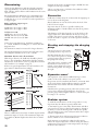
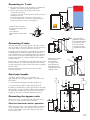
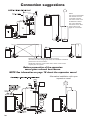
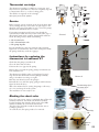
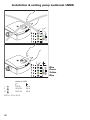
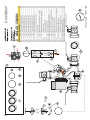
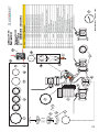
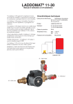
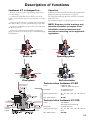
Description of functions
Laddomat 21 is designed to...
Operation
...allow the boiler to reach a high working temperature
soon after firing.
Laddomat 21 functions fully automatically provided that
pump start and stop is automated. See page 16.
...to preheat the cold tank water in the bottom of the
boiler so that the boiler does not rust away due to condensation.
The settings described in this User manual are normally
made only once.
…charge the tank with water at a high and even temperature and low flow, to ensure optimal layering in the tank.
…transfer the residual heat in the boiler to the tank after
the fire has gone out.
…in the event of electrical power failure stopping the
pump, transfer the heat in the boiler to the tank through
self-circulation.
The Laddomat requires no special supervision or service.
NOTE! Diagrams in this brochure only
describe connection principles. Each
installation must be measured and
carried out according to the applicable
regulations.
Operating phase
Start up
Final phase
Self-circulation
Technical data Laddomat 21-60
Connection to
top of boiler
Pump:
Laddomat LM6
Laddomat LM6A ErP 2015
Connection:
3 x Cu28 with lever
3 x R32 with lever
Opening temperature:
53°, 57°, 63°, 66°, 72°, 78°, 83° or
87°C
Max. boiler output:
60 kW
Technical data Laddomat 21-100
Connection
to bottom
of boiler
Connection
to bottom
of tank
Pump:
Wilo RS25-7
Wilo Yonos Para ErP 2015
Connection:
3 x R32 with lever
Opening temperature:
53°, 57°, 63°, 66°, 72°, 78°, 83° or
87°C
Max. boiler output:
120 kW
15
Dimensioning
Generous pipe dimensions and short lengths guarantee
operating reliability, even when the demand for heat is
high. This also allows effective self-circulation in the event
of power failure.
Example: If the boiler’s nominal output is 40 kW, the max
output can reach up to 60 kW.
This is very important to include in the calculation when
dimensioning the system.
Recommended pipe dimensions for a maximum boilerto-tank distance of 2 m. Total length boiler-tank-boiler
would then be 2 + 2 m + 6 bends. 1 bend is equivalent to
1 m pipe length.
Connection
Boiler with max output* up to:
Laddomat 21-60:
Place Laddomat 21 near the boiler and at the level of the
boiler’s bottom output.
45 kW min. 28 Cu pipe or R25
60 kW min. 35 Cu pipe or R32
Pipe-runs must be as short as possible and have the
minimum number of bends. Make sure that all air pockets
are eliminated.
Laddomat 21-100:
80 kW min. 35 Cu-rör alt. R32
100 kW min. 42 Cu-rör alt. R40
120 kW min. 54 Cu-rör alt. R50
Flow:
At the above pipe dimensions, Laddomat 21-60 gives
2 – 3 m³/h. Laddomat 21-100 gives 3 – 4m³/h. See flow
diagram below.
The dimensions must be increased for longer distances.
The maximum distance between boiler and tank is 6 m.
Total length would then be 6 + 6 m + 6 bends.
Maximum distance and self-circulation
With longer distance, the Laddomat should be placed
closer to the accumulator. Remember that flow capacity
will decrease, both when it comes to pump flow as well as
self-circulation. See example on page 6.
If there are special requirements for self-circulation, the
pipes must be dimensioned accordingly.
Laddomat 21 must always be connected in the upright position as shown in the diagrams.
The diameter of the pipe from the top of the boiler to the
T-pipe and down to the Laddomat 21 must be as large as
possible. This gives low water velocity, and allows air released in the boiler to separate out in the expansion chamber
or the vent.
Starting and stopping the charging
pump
The speed control on the circulation pump must be in position 3.
NOTE! Check that the control is
not at the lowest speed or a neutral
position because this can prevent
the pump from starting.
The pump can be started by a flue
thermostat. If extra safety is required, a water thermostat can be
connected in parallel. See image to
the right.
Expansion vessel
The expansion vessel must be sufficiently large, at least
5–10% of the total volume for an open system.
If a pressure vessel is installed, this must be at least 10–20%
of the total volume. Each installation must be specially
dimensioned in accordance with the manufacturer’s
instructions.
Check that the operating pressure, when the system is cold,
is never lower than the height difference between the
pressure gauge and the highest radiator + 2 metre water pillar (mwp, 1 m = 0,1 bar).
Radiator system
To make the maximum use of the storage tank, it is very
important that the radiator system is fitted with:
*Boiler output:
There is a difference between the nominal output and the
maximum output of a boiler. The maximum output can
be as much as 30-50% higher than the boiler’s nominal
output.
16
1. Automatic by-pass control like Thermomatic with flow
sensor and room sensor is ideal for this purpose, thanks to
its ability to sense the heating needs of the house rapidly.
The automatic by-pass control always matches heat output
exactly to requirements.
2. Thermostatic valves with integrated pressure reduction
devices, which are set to suit the radiator size.
Both measures are intended to reduce the flow and so
reduce the return temperature, without raising the delivery
temperature. The lower the return temperature, the longer
the heat in the tank lasts.
Connecting to 1 tank
1. The pipe-runs shown on the diagram are optimised to
minimise air-related operating interruptions.
2. The hot water pipe to the by-pass valve can be
connected in two ways.
A. Approx 30 cm from the top of the tank to prioritise
domestic hot water.
B. On the charge line connection to the tank to
prioritise heating. The connection is directed downwards to prevent air rising to the radiators.
Laddomat 21 can easily
be reversed for right-hand
mounting.
Just move the
thermometers to the other
side.
The pipe to the
bottom of the tank
must not be routed
through the roof.
This connection
removes the selfcirculation function.
Connecting 2 tanks
The tanks must be located up against each other, and as
close as possible to the boiler. The pipe-runs from the bottom of the tanks are always laid close to the floor.
It is important that the flow to the tanks during charging
and discharging is distributed equally. If the system is
connected incorrectly, then charging will be cut off when
tank 1 is full of hot water which will reach the boiler before the other tanks are completely filled. Tank 2 will be
virtually unused.
If the system is connected incorrectly, the warm water and
the heat will run out earlier than estimated after the burner has stopped, since tank 1 will cool down more quickly
than the other.
If these requirements cannot be met, there are other
connection options.
NOTE If the radiator
is connected in
this way there
is a large risk of
heat retention in
the boiler and/or
reduced heat to the
radiator circuit.
Equal pipe lengths
To achieve equal resistance, it is essential to use
approximately the same pipe-lengths to the tanks, this is
achieved by:
1. Connecting the charging circuit diagonally, A–A.
2. Connecting the radiator circuit diagonally, B–B.
In addition, the dimension of the pipes between the tanks
must be large enough to facilitate self-circulation between
the tanks. It is an advantage if the tanks are connected
together in the centre, to further distribute the heat.
Connecting the by-pass valve
The hot water port is connected at B, which prioritises
hot water, or at B1, which prioritises heating.
Electrical immersion heater operation
When operating solely on the electrical immersion heater,
it is an advantage only to heat the first tank to prevent
heat loss. Shut off the other tank using the valve at the
bottom of the tank.
17
Connection suggestions
NOTE
This type of installation
will remove the selfcirculation function.
The check valve must
be blocked to lower
the risk of keeping
the boiler warm. See
picture 5 on next
page for instruction.
Recommended installation with longer distance
To make sure the charging will work, the Laddomat should be
placed near the accumulator.
NOTE long distance means lower flow, which means lower
capacity for the system.
Bottom connection of the expansion
vessel gives reduced heat losses.
NOTE See information on page 16 about the expansion vessel
Alternative installation with open
expansion vessel
18
Thermostat cartridge
The thermostat cartridge is available as a spare part, and
may need to be replaced more often if it is regularly exposed
to temperatures close to, or above, boiling point.
The number is engraved on the cartridge.
See spare parts list for options
Service
Before carrying out any servicing work, close the three shutoffs by turning the lever on the valves at right angles to the
direction of the pipe. This makes it easy to access the pump,
thermal valve and check valve for service.
If operating interruptions still occur, even though the
system has been bled, there may be dirt such as lint, tape or
thread swarf stuck in the coupling. Disassemble and clean.
Clean all sealing surfaces when reassembling:
Picture1
1. The thermal valve
2. The self-circulation valve
3. The pump impeller
In some installations, there are problems with extremely
high levels of contaminants. These can form deposits inside
the pump, which may result in stoppages.
Instructions for replacing the
thermostat in Laddomat 21
Picture 2
Check that the pump is switched off.
Close the three shut-off valves.
Unscrew the cover opposite the pump.
Remove the cover with the spring, plunger and thermostat
from Laddomat 21.
The thermostat is held in place on the plunger by an Oring. Detach the thermostat from the plunger carefully
using a screwdriver (see image on right).
Picture 3
Push the new thermostat into the plunger.
Reinstall the cover with the spring, plunger and thermostat.
Open the shut-off valves.
The blocking clip is
mounted here.
Wait a few minutes before starting the pump to allow any
air to rise and escape from the system.
The installation is now ready for use.
Blocking the check valve
If you, for some reason, want to completely shut off the self
circulation function, the check valve must be blocked.
Use the blocking clip, placed at the bottom of the EPPinsulation (Picture 3), to block the check valve.
The clip is then fastened around the check valve axis according to picture 5.
To reach the axis, the spring needs to be removed.
Laddomat
21-60
Picture 4
Picture 5
Blocking
clip
Laddomat
21-100
19
Installation & setting pump Laddomat LMXA
Blue
Green
Yellow
Blue
Laddomat LM6A
I
7-50 W
16 W
II
10-50 W
34 W
III
12-50 W
50 W
230 V ± 10 %, 50 Hz
20
70
73