1
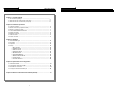
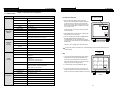
STAND-ALONE DVMR
8 Channel Digital Video Multiplex Recorder
RECORDER
ALL ABOUT IMAGE RECOGNITION & PROCESSING
DIGITAL VIDEO
STAND-ALONE DVMR
DIGITAL VIDEO RECORDER
User’s Manual
VER 2.0
Stand-alone DVMR
The most stable and reliable real stand-alone Digital Video Multiplex Recorder
ALL ABOUT IMAGE RECOGNITION & PROCESSING
8Channel stand-alone DVMR
8Channel stand-alone DVMR
ALL ABOUT IMAGE RECOGINITON & PROCESSING
SAFETY PRECAUTIONS
CAUTION
RISK OF ELECTRIC
SHOCK. DO NOT OPEN!
CAUTION : TO REDUCE THE RISK OF ELECTRICAL SHOCK, DO NOT OPEN COVERS.
NO USER SERVICEABLE PARTS INSIDE. REFER SERVICING TO QUALIFIED
SERVICE PERSONNEL.
This label may appear on the bottom of the unit due to space limitations.
The lightning flash with an arrowhead symbol within an equilateral triangle is intended to
alert the user to the presence of uninsulated “ dangerous voltage” within the product’s
enclosure that may be of sufficient magnitude to constitute a risk of electric shock to
persons.
The exclamation point within an equilateral triangle is intended to alert the user to presence
of important operating and maintenance (Servicing) instructions in the literature
accompanying the appliance.
WARNING : TO PREVENT FIRE OR SHOCK HAZARD, DO NOT EXPOSE UNITS NOT
SPECIFICALLY DESIGNED FOR OUTDOOR USE TO RAIN OR MOISTURE.
Attention: installation should be performed by qualified service Personnel only in accordance
with the National Electrical Code or applicable local codes.
Power Disconnect. Units with or without ON-OFF switches have power supplied to the unit
whenever the power cord is inserted into the power source ; however, the unit is operational
only when the ON-OFF switch is in the ON position.
The power cord is the main power disconnect for all unites.
ALL ABOUT IMAGE RECOGINITON & PROCESSING
8Channel stand-alone DVMR
8Channel stand-alone DVMR
ALL ABOUT IMAGE RECOGINITON & PROCESSING
ALL ABOUT IMAGE RECOGINITON & PROCESSING
FCC INFORMATION
A CLASS A computing device subject to certification by the Commission shall be identified pursuant to
par.2.925 et Seq of the chapter. In addition, the label shall include the following statement:
This device complies with Part 15 of the FCC Rules.
Operation is subject to the following two conditions:
(1)This device may not cause harmful interference, and
(2)This device must accept any interference received,
including interference that may cause undesired operation.
Where a device is constructed in two or more sections connected by wires and marketed together,
the statement specified in this Section is required to be affixed only to the main control unit.
The users manual or instruction manual for the EUT shall contain the following statement or eqivalent.
Caution : Changes or Modifications not expressly approved by the party responsible for compliance could void
the users authority to operate the equipment.
If the EUT requires accessories such as special shielded cables and/or connectors to enable compliance with
emission limits, the instruction manual for the EUT shall include appropriate instructions on the first page of the
text concerned with the installation of the device that these special accessories must be used with the device.
It is the responsibility of the user to use the needed special accessories supplied with the equipment.
For a CLASS A digital device or peripheral, the instructions furnished the user shall include the following or
similar statement placed in a prominent location in the text of the manual.
Note : This equipment has been tested and found to comply with the limits for a CLASS a digital device,
pursuant to Part 15 of FCC Rules. These limits are designed to provide reasonable protection against
harmful interference when the equipment is operated in a commercial environment. This equipment
generates, uses and can radiate radio frequency energy and, if not installed and used in accordance
with the instruction manual, may cause harmful interference to radio communications. Operation of the
this equipment in a residential area is likely to cause harmful interference in which case the user will be
required to correct the interference at his own expense.
Table of Contents
8Channel stand-alone DVMR
ALL ABOUT IMAGE RECOGINITON & PROCESSING
Chapter 1 . Product package
1-1. The contents of package ------------------------------------------------------------------------------ 3
1-2. Name and function of each button (front panel) -------------------------------------------------- 4
1-3. Name and function of each button (rear panel) -------------------------------------------------- 5
Chapter 2. Installation procedure
2-1. Camera connection ------------------------------------------------------------------------------------- 6
2-2. Monitor connection (Composite monitor) ---------------------------------------------------------- 6
2-3. Monitor connection (S-VHS) ------------------------------------------------------------------------- 7
2-4. VCR & VIDEO PRINTER connection --------------------------------------------------------------- 7
2-5. Sensor connection ------------------------------------------------------------------------------------- 8
2-6. Network connection ------------------------------------------------------------------------------------- 8
2-7. HDD connection ------------------------------------------------------------------------------------------ 9
2-8. Power connection ---------------------------------------------------------------------------------------- 9
Chapter 3. Operation
3-1. DVR SYSTEM Log-in ----------------------------------------------------------------------------------- 10
3-2. Recording ------------------------------------------------------------------------------------------------- 11
3-3. Playback ------------------------------------------------------------------------------------------------- 14
3-4. Set-up --------------------------------------------------------------------------------------------------- 16
1. Basic operation ----------------------------------------------------------------------------------2. CAMERA SETUP --------------------------------------------------------------------------------3. DISPLAY SETUP -------------------------------------------------------------------------------4. TIME/DATE SETUP ---------------------------------------------------------------------------5. RECORD SETUP --------------------------------------------------------------------------------
16
16
17
19
19
6. HDD MANAGEMENT---------------------------------------------------------------------------- 21
7. MISCELLANEOUS SETUP -------------------------------------------------------------------- 21
8. TCP/IP SETUP ------------------------------------------------------------------------------------ 24
9. FACTORY DEFAULT ---------------------------------------------------------------------------- 26
Chapter 4. Specification and Configuration
4-1. SPECIFICATIONS --------------------------------------------------------------------------------------- 27
4-2. Configuration Stand-alone DVMR ------------------------------------------------------------------- 28
4-3. RS-232C Hex-code table ------------------------------------------------------------------------------ 28
4-4. Arrange of RS 485 and RS-232C pin --------------------------------------------------------------- 29
Chapter 5. Menual for Remote Viewer Software(TCP/IP)------------------------------------- 30
1
8Channel stand-alone DVMR
ALL ABOUT IMAGE RECOGINITON & PROCESSING
ALL ABOUT IMAGE RECOGNITION & PROCESSING
8Channel stand-alone DVMR
5.Menual for Remote Viewer Software(TCP/IP)
8Channel stand-alone DVMR
ALL ABOUT IMAGE RECOGINITON & PROCESSING
ALL ABOUT IMAGE RECOGINITON & PROCESSING
Speed of playback in DVMR unit according to scan rate set in 4-7-b).
Scan rate set in 4-7-b)
1x
2x
4x
8x
16x
32x
64x
or
1x
1x
1x
1x
1x
1x
1x
About this document
or
1x
2x
4x
8x
16x
30x
60x
Before installing stand alone DVMR, be sure to thoroughly review and follow the instructions in this
User’s Manual. Pay particular attention to the parts those are marked NOTICE.
Also, when connecting with external application, first turn the power OFF and follow manual
instruction for appropriate installation.
Maximum playback speed of DVMR is 60x.
10 : Command button.
We have 3 different buttons, that are, save, print, and event, and those buttons work only when stop
button is pressed.
a) Save
During searching recorded pictures, you can save pictures one by one in the folder in client PC by
pressing save button. Press Save button while you see recorded picture, and picture you selected
by pressing Save button shall be save on the folder you already assigned under the file name of
year-month-day-hour-minute-second in jpg format.
b) Print
During searching recorded pictures, you can print picture, one by one, you see, by pressing Print
button.
c) Event
Press event button to see alarm list saved in DVMR unit, and you can search recorded pictures
based on event list by clicking any one of list.
11 : Calendar.
You can select date and time to search pictures recorded at selected time and date. You can refer to
start and end of recording in 7.
Notice : From time to time, connection shall be cut unexpectedly due to conditions of network line.
Whenever it is cut, quit search window by pressing power switch(1), and then press connect
button in live-view window and scan button to enter into search window again, to continue
searching.
Notice : Compatibility of Remote Viewer Software with different kinds of operating systems and PC
hardware may not be simply specified due to the characteristics of network that it is much
related with not only PC hardware and operating system but also other software installed
on the client PC and conditions of network (internet) line. Basically, Remote Viewer Software
is compatible with typical Windows operating system from Windows 98 to Windows XP.
Before reading this
document
1. This document is intended for both the administrator and users of stand alone DVMR.
2. This manual contains information for configuring, managing and using stand alone DVMR properly.
3. To prevent fire or electrical shock, do not expose the product to heat or moisture.
4. Be sure to read this manual before using stand alone DVMR Model, even before installing HDD.
5. Check electricity at the place you want to install the DVMR unit is stable and meets our
electricity requirements.
Unstable electricity will cause malfunction of the unit or give critical damage to the unit.
6. Several chips on the main board of the DVMR unit and hard disk drive inside the unit generate
heat, and it must be properly discharged.
Do not put any objects just beside exhaust port(fan) on the left side of the unit and do not close
up an opening (fresh air in-take) on the right side of the unit..
7. Put the DVMR unit at well-ventilated place and do not put heat-generating objects on the unit.
When it is installed inside 19 inch mounting rack together with other devices, please check builtin ventilation fan of the rack is properly running.
8. For questions and technical assistance of this product, contact your local dealer.
Notice : To see continuous live view, we recommend not to select motion recording in RECORD
SETUP menu of DVMR. If it is set at motion recording in SETUP menu of DVMR, image
transmission is done only there is motions detected.
Notice : While you search recorded data using client software in client PC, DVMR unit to which you
access via IP network is in playback mode, and no recording is done as far as you search
recorded data. However, while you are in connection with DVMR unit via IP network for live
view, DVMR unit continues to record but at a little lowered recording rate. Therefore we
recommend you to access to DVMR unit only when it is necessary.
37
2
Product package
8Channel stand-alone DVMR
5.Menual for Remote Viewer Software(TCP/IP)
8Channel stand-alone DVMR
ALL ABOUT IMAGE RECOGINITON & PROCESSING
Chapter 1 . Product Package
ALL ABOUT IMAGE RECOGINITON & PROCESSING
5. Search recorded pictures via IP network
1
Chapter 1 . Product Package
7
1. 8 ch stand-alone DVMR unit
8
2
3
10
4
66
9
5
2. User’s manual for 8 ch DVMR
Describe how to install and operate this DVMR unit.
3. Remote controller
IR remote controller enables an user to operate DVMR unit
apart from the unit.
4. DC power adapter and power cable
Convert AC 110V or AC 220V into DC 12V to supply to DVMR unit.
Function of each button in search window :
1: Power switch. Press power switch to quit.
2: Full screen button. Press full screen button to search recorded picture channel by channel in full screen.
3: Quad button. Press Quad button to search recorded pictures in quad screen, 4 pictures from 4 channels
at the same time.
4: Screen division button : If press “+” button, it screen division is changed from 4 to 9 or from 9 to 16. “-“
button reduce screen division.
5: Time of recording. It indicates when the pictures you see recorded.
6: Channel selection button. Press any one from 1 to 4 to see picture of corresponding channel, if you first
chose full screen button(2).
7: Time selection button. You can set time to search by dragging yellow mover to the left or right. See time
displayed in green color and find an exact time from which you search.
8: Start and end of recording. It shows time from which recording started and recording ended. Further it
show time from which search will start.
9: Search operation button. You can search recorded data using various buttons useful for searching
effectively as follows.
: Play fast backward
(Speed set in SYSTEM SETTING)
: Move to start of recording
(Press stop button first before this button)
: Play Backward(x1)
: Move to previous hour (on the hour).
Press stop button first before this button.
: Play forward(x1)
: Move to next hour (on the hour)
: Play fast forward
(Speed set in SYSTEM setting)
: Move to end of recording
(Press stop button first before this button)
: Stop
3
36
8Channel stand-alone DVMR
5.Menual for Remote Viewer Software(TCP/IP)
1. Unit Description
8Channel stand-alone DVMR
ALL ABOUT IMAGE RECOGINITON & PROCESSING
ALL ABOUT IMAGE RECOGINITON & PROCESSING
1-2. Name and function each button (front panel)
1
13
6
2
3
4
5
6
7
8
9
10
12
14
1. POWER SWITCH WITH LED : DC power switch with LED
Generally speaking, cutting power to system may cause trouble in DVMR
system or damage to HDD when HDD is in writing process, and we ask you
to press [MENU] button first to protect HDD from being damaged or system
failure before you press DC power switch off in practical operation.
2. MENU : Used to check or change parameters settings in SYSTEM SETUP. After pressing [MENU] button,
input password and press [ENTER] button to enter into SYSTEM SETUP.
USER PANTILT COMMAND
- It is to input protocols for specific PTZ camera you will connect to 16ch DVMR unit, to control PTZ
camera while you see live pictures in the client program.
- You can save protocols of specific PTZ camera in the form of computer file (text file). Prepare text file of
protocol for PTZ camera and save it on your PC. In the User Pantilt Command window, press [Menu]
button and again press [Load User PT File]. Then you can assign text file of protocol for PTZ camera you
pre pared in advance. It is very convenient function.
- If you want to control PTZ camera using buttons on the front of 16ch DVMR unit, you must input the same
protocol into DVMR unit in PAN/TILE CMD SETUP.
b) Scan. : Press scan button to enter into search window. Using various operation buttons, you can
search recorded pictures, save selected pictures on client PC, or print pictures. Refer to
following paragraph “3. Search recorded pictures over IP network” for details
8) PTZ control. You can control Zoom, Focus, and Pan/Tilt of camera while you see live pictures via IP network.
Of course, you must first input PTZ protocol for a specific PTZ camera you connected to your DVMR unit,
into your DVMR unit. You can control PTZ camera with various of commands in USER PANTILE COMMAND
window above.
When you press corresponding buttons for Pan/Tilt control, press a couple of second every time you press to
take care of data transmission speed through IP network. Otherwise, there is a possibility that given protocol
is transmitted repeatedly, regardless of your intention.
Notice : From time to time, connection shall be cut unexpectedly due to conditions of network line, and you
will see disconnect button(3) is activated. Just press connect button(2) again, and you can continue
to see live pictures.
35
3. PLAY/ENTER : Starts playback, and in some functions, it is used as the SELECT key. Press shortly and
it starts playback. If you press this button for a long time, you enter into GO TO menu to
start playback from image you want to start.
4. MODE : Changes screen division. Whenever you press [MODE] button, screen division is changed from
full screen to 4-split screen, 9-split screen in sequence, both in live or playback mode.
To change channel in full screen mode, just press number button. If you press [MODE] button for
a lone time, it changes type of monitor connected to DVMR unit form COMPOSITE to VGA,
or from VGA to COMPOSITE, in case VGA option is included in DVMR system.
5. P/T : Manages PAN/TILT CONTROLLER. To control PTZ camera connected to DVMR unit, you have to
select model of PTZ camera in PAN TILE CMD SETUP/MISCELLANEOUS SETUP.
6. 1/5,2/6,3/7,4/8 : Chooses each indicated camera in full screen mode. Each button is double number button,
and pressing [1], [2], [3], and [4] for a very short time is for 1, 2, 3, and 4 respectively, and
pressing [1], [2], [3], and [4] for a long time is for 5, 6, 7, and 8 respectively.
7. PIP : Assigns PIP (Picture In Picture)
8. FRZ : : Displayed screen is paused.
9. SEQ : To see display screen in rotation from channel number 1, 2, 3, and so on, both in live and playback
mode. It also change Quad screen from 1/2/3/4 to 5/6/7/8.
10. ZOOM : Enlarges the display screen by 200%. Digital zooming.
11. Remote Controller Sensor Input Window
12. Direction button : [LEFT], [RIGHT], [UP] and [DOWN].
In playback mode, [LEFT] and [RIGHT] buttons are for selecting playback
direction (forward/backward), and [UP] and [DOWN] buttons are for increasing or
decreasing speed of playback.
13. LED Lamps : Represent status of operation. OVERWRITE/RECORD/PLAYBACK/SETUP.
14. CD-RW DRIVE
NOTICE : If the Input window (IR receiver) is covered, the remote controller may not work.
NOTICE : If several buttons are simultaneously or incorrectly pressed, the system may not be
operated unproperly.
4
1. Unit Description
8Channel stand-alone DVMR
ALL ABOUT IMAGE RECOGINITON & PROCESSING
1
3
5.Menual for Remote Viewer Software(TCP/IP)
ALL ABOUT IMAGE RECOGINITON & PROCESSING
7) : Set button. 2 different set buttons
a) Setting : Press this button to input IP Address(or select a unit of 16 ch DVMR unit among many)
and others and to set circular monitoring interval and scan rate, to assign folder where you
want to save pictures you will select during search, to input protocol for PTZ cameras or
select any model of PTZ cameras among many models whose protocols you already input,
as following dialog box.
1-3. Name and function each button (Rear panel)
2
8Channel stand-alone DVMR
4
6
5
7
8
9
10
1. RS-232C Port Connection
2. Sensor Input/Output
3. LAN (TCP/IP)
4. Camera Connection
CONNECTION
- On the Name box, you are requested to input name of 16ch DVMR units, in case you want to access to
any one DVMR unit among more than a unit. You can save IP information in Configurations Window and
select name of DVMR unit to which you want to access.
- Input IP Address you already input into DVMR unit (TCP/IP SETUP) in IP ADDRESS.
- Input Port number you already input into DVMR unit in PORT. Just input 8000, which is default port number.
In some cases, port number 8000 is blocked by firewall, and you have to input different number like 8090
which is not blocked.
- Input “admin” in ID.
- Input the same password you set into DVMR unit in PASSWORD. Default password of 16ch DVMR
unit is blank (null). You are requested to enter your own password using number keys from 1 to 16 on
front panel of 16ch DVMR unit
5. LOOP Output
6. VCR Connection
7. MONITOR Connection
8. VGA Connection
9. S-VHS Connection
10. D/C Power Connection
NOTICE : When connecting with other applications, be sure to turn off the system.
OPTION
- Select circular monitoring interval ranging from 0.1 sec to 10 sec. The smaller it is, the faster picture
of each channel rotates. The absolute circulation interval is a little different from set value depending
on data transfer rate of IP network.
- Select scan rate ranging from 1x to 64x. The larger it is, the faster search speed is. The absolute
search speed is a little different from set value depending on data transfer rate of IP network.
- Reconnection count : In case disconnected due to some reason, client program tries to reconnect after
this time.
SAVE OPTION
It is to assign folder on which you want to save pictures you will select while you search recorded
pictures, picture by picture.
5
34
5.Menual for Remote Viewer Software(TCP/IP)
8Channel stand-alone DVMR
ALL ABOUT IMAGE RECOGINITON & PROCESSING
2. Installation
8Channel stand-alone DVMR
ALL ABOUT IMAGE RECOGINITON & PROCESSING
Chapter 2. Procedure
2-1. Camera Connection
Connect the camera to the CAMERA INPUT on the Rear Panel of the system.
Now, hit the "Release" button and then hit "Renew". If all goes well, you'll get new information, and it is for your
DVMR unit. Write down this information on separate paper and input IP Address, Subnet Mask, and Default
Gateway into your DVMR to which you want to access via IP network.
⒞ Confirm if IP Address is working by executing pingtest
Execute pingtest with IP Address which you assigned to DVMR unit, check if it is successful before you try to
access to DVMR unit via IP network. If it is not successful, you may not be able to access to DVMR unit via
IP network, and we recommend you to get help from your network administrator.
4. Live view via IP network
Click Remote Viewer icon to view live pictures via IP network. You will see then following window.
Rear part of CAMERA
2-2. Monitor Connection (Composite Connection Method)
Connect the monitor to the MONITOR OUT on the Rear Panel of the system
1
6
7
8
4
2
3
Screen positioning : If picture displayed in your monitor is not at the center of monitor, you can relocate
5
Function of each button in live-view window :
1) : Power switch. Press power switch to quit. Before press power switch button, press disconnect button first.
2) : Connect button. Press connect button to connect to DVMR unit via IP network to see live pictures of DVMR
unit. You will see the same live pictures, which are displayed on monitor of DVMR unit with a certain time
delay depending on transfer rate of IP network.
3) : Disconnect button. Press disconnect button to cut connection to DVMR unit via IP network.
4) : Screen division button. You can select to see pictures of any single channel, 4, 9, and 16 channels at the
same time. You can select channel number from 1 to 16 to see pictures of selected channel. If you
selected 4, you swill see channel number from 1 to 4 are all activated.
5) : Channel number button. You can select channel number to see live pictures from selected channel.
6) : Status window. It shows Date and Time. Further it displays “Connection established” and a circular fan on
the left bottom is rotating when connection button is activated, or “Waiting for connection” when
disconnection button is activated.
33
images to make them shown in the middle of monitor.
Press [P/T] button for a long time to enter into screen position mode, and you
can adjust location of pictures using [UP], [DOWN], [LEFT] and [RIGHT]
buttons. Press [P/T] button for a long time again to quit screen positioning mode.
If you press [ENTER] button in the process of screen positioning mode, location
of pictures return to original location set by manufacturer.
Notice : Connect camera or monitor to DVMR unit while DC power switch on the front panel is off.
6
2. Installation
8Channel stand-alone DVMR
8Channel stand-alone DVMR
ALL ABOUT IMAGE RECOGINITON & PROCESSING
2-3. Monitor (S-VHS) Connection
Connect S-VIDEO Monitor to MONITOR OUT(S-VHS) on the Rear Panel of the system.
5.Menual for Remote Viewer Software(TCP/IP)
ALL ABOUT IMAGE RECOGINITON & PROCESSING
3. How to get IP for DVMR unit
There is 2 different ways to input IP address and other data into DVMR unit.
The first way is to make DVMR system get IP address from DHCP server automatically.
It is only possible in case DVMR unit is connected to cable modem (dynamic IP), Intranet under DHCP
server or IP sharer which support DHCP. Select “DHCP” in TCP/IP setup to get IP address automatically.
The second way is you get IP address and other data before you connect DVMR unit to network and later
input this IP address and other data into DVMR unit. Except the case you already know IP address
assigned for DVMR unit, get IP address for DVMR unit as following process in the client PC from which
you want to access to DVMR unit via IP network. If you connect DVMR unit to leased line with static IP
already known, it is not necessary to follow following process to get IP information.
a) “ipconfig” or “winipcfg”
Execute “ipconfig” command in the client PC with Windows 2000 and Windows XP, and “winipcfg”
command in the client PC with Windows 98 and ME, and you will get IP informations, that are IP Address,
Gateway, Subnet Mask. Write down those numbers and input into DVMR unit to which you are going to
access via IP network. As far as DVMR is in operation without turning off, it is considered that this IP
2-4. VCR & VIDEO PRINTER Connection
Address is assigned just to this DVMR unit. Then, restart the client PC to get different dynamic IP address
Connect VCR or VIDEO PRINTER to VCR OUT on the Rear Panel of the system.
for client PC after you get IP information for DVMR unit. Derail procedure to get IP information in different
Windows is as follows.
ⓐ Window 2000
First you need to get to the command prompt using the command shell. The best way is from the
run menu.
Start--> Run --> and type in Command. Then either hit enter or click OK. At the command prompt,
type in ipconfig. This will pull up the information that you need to find IP Address for DVMR unit.
ⓑ Windows XP
If you want to get IP Address for your DVMR in Windows XP, you can run ipconfig in one easy step.
Open Run and type "cmd /k ipconfig" without the quotes. This will open the command prompt and
start ipconfig the easy way. Assign IP Address you get to DVMR unit.
ⓒ Windows 98 and ME
To run winipcfg, grab the Run item from the Start menu and type winipcfg into the Open: box. Hit
OK (or RETURN). Those comfortable with DOS can launch it from a DOS prompt.
When winipcfg launches, you'll get a window like this one:
7
32
8Channel stand-alone DVMR
5.Menual for Remote Viewer Software(TCP/IP)
ALL ABOUT IMAGE RECOGINITON & PROCESSING
c) ADSL(ADLS modem with PPPoE protocol) line with static IP or dynamic IP.
2. Installation
8Channel stand-alone DVMR
ALL ABOUT IMAGE RECOGINITON & PROCESSING
2-5. Sensor Connection
You can connect dry-contact type sensors. In case of sensors with TTL output (5 Volts system), GND of
sensor must be connected to GND of DVMR unit and signal line to alarm input from D1 to D16 as shown
in following figure.
Short-circuit between any of D1 from D16 and GND is recognized as an alarm.
All GNDs are connected to each other on circuit.
Example of IP Forwarding in website of Router or Gateway
DVMR-16
PC
Client program
DVMR-2
ADSL Modem
Router/Gateway
DVMR-1
IP forwarding is what we have to set in web site of Router or Gateway to connect external Port to internal IP
assigned by Router or Gateway.
d) In the same Intranet : Supports
Relay output is output in case there is an alarm input, and is connected to external device using
COM-NO (Normal Open) or COM-NC (Normal Close) contact.
2-6. Network Connection
- LAN under DHCP (Dynamic Host Configuration Protocol) Server
RS-232C : Connection to PC to operate DVMR
RS 485 : Connection to PTZ camera
RJ-45 (ETHERNET) : Connection to LAN, WAN or Internet
VGA : Connection to PC monitor
For more details, refer to arrangements RS-232c pins in page 29.
31
8
2. Installation
8Channel stand-alone DVMR
ALL ABOUT IMAGE RECOGINITON & PROCESSING
8Channel stand-alone DVMR
5.Menual for Remote Viewer Software(TCP/IP)
ALL ABOUT IMAGE RECOGINITON & PROCESSING
Chapter5. Manual for Remote Viewer Software (TCP/IP)
2-7. HDD connection
Connect main board and HDD using IDE HDD cable and power
cable included in the package. If you install a unit of HDD, jumper
Setting of HDD must be on (DS) Master, as specified by HDD
manufacturer.
Fix HDD on the bottom of DVMR case using screws included in
the package. Screws must be inserted from outside of the bottom.
And CD-RW drive must be on Slave.
Notice : Formatting before installation is not required, because
DVMR system automatically detects and formats HDD.
In the first operation after installation of HDD, first
set at FACTORY DEFAULT in setup menu of DVMR
system and then do HDD CLEAR in HDD MANAG
EMENT in setup menu of DVMR system.
General description : TCP/IP option enables users to view live pictures, search recorded pictures, or control
PTZ camera via Internet line, far apart from the DVMR unit, and users can store selected recorded pictures
on HDD of client PC. Our stand-alone DVMR does not adopted web browser method for access to DVMR
unit via Internet line, and you must install Remote Viewer software included in the package on client PC
before you try to access to DVMR unit over IP network.
1. TCP/IP SETUP in DVMR unit
Before you install Remote Viewer software, be sure to input IP address and others in TCP/IP SETUP of
DVMR unit. Then, execute SETUP.exe on Remote Viewer software CD included in the package of
stand-alone DVMR with TCP/IP option.
Notice : In case you see “UNKNOWN HDD DETECTED” message is displayed after booting process,
just clear HDD and set at FACTORY DEFAULT to make this HDD be detected by DVMR system.
2-8. Power Connection
DVMR
Connect the power to the POWER CONNECTION on the Rear Panel of the system,
and turn on the switch.
Install client software (Remote viewer) to access to DVMR unit via Internet line.
Notice : To turn off DC power switch on the front panel of DVMR case, be sure to press [MENU] button first.
If you press [MENU] button, DVMR system stops recording, and you can cut power to DVMR unit
while HDD head is not in writing mode. It is necessary to press [MENU] button first and turn DC
power switch off for protection of HDD head from being damaged and eliminate possibility of
mal-function of DVMR unit.
2. Conditions of IP network
To access to our DVMR unit via IP network, you have to connect DVMR unit to IP network as one of
followings and assign IP address, Subnet mask, and Gateway to our DVMR unit. Our DVMR unit accepts
static IP and it also work in case both DVMR unit and client PC are connected to the
same Intranet (LAN).
a) Static IP : If DVMR unit is connected to leased line with static IP, we can access to DVMR unit via
Internet line far apart from DVMR unit. (DHCP SETUP in TCP/IP SETUP : MANUAL
(Input IP address manually)
b) Cable modem with dynamic IP : If DVMR unit is connected to cable modem with dynamic IP,
we can access to DVMR unit via Internet line far apart from DVMR unit.
Turn on the POWER and Log-in to the system
Follow instruction in the Log-in part of this manual to input the PASSWORD and start the system.
Factory default password for account manager and user, set by manufacturer, is null, therefore
just press [ENTER] button in case DVMR system asks to input password, as far as you did
not change password.
Detail setup in SYSTEM SETUP
For detail setup, refer to the instruction of SYSTEM SETUP.
9
30
4. Configuration
8Channel stand-alone DVMR
3. Operation
8Channel stand-alone DVMR
ALL ABOUT IMAGE RECOGINITON & PROCESSING
ALL ABOUT IMAGE RECOGINITON & PROCESSING
4-4. Arrangement RS-232C and RS-485 pin
Chapter 3. Operation
3-1. DVMR SYSTEM log-in
RS-232C
1) Press [MENU] button to enter the
system menu after starting the system.
Pin No.
Definition
1
NC
2
RxD
3
TxD
4
SD-(RS 485)
5
GND
6
SD+(RS 485)
7
NC
8
NC
9
NC
2) DVMR system asks you to enter
password to verify authority of user as
shown on the left.
3) When you get the DVMR, you can enter
into Setup menu by just pressing
[ENTER] button.
4) In case you already have changed
the password, enter your own
password.
Login DVMR SYSTEM
5) Press [ENTER] button after you enter password, to enter into SETUP menu.
6) After entering to setup menu, press [MENU] button to go back to the system menu.
If password entered matches previously set password, “PASSWORD OK” message appears and you
can enter into SYSTEM SETUP.
DVMR unit
Other device (PC)
If password entered does not match previously set password, DVMR system just go back to initial mode,
that is, showing live pictures and recording as set before.
Factory default password is [ENTER]
D-SUB 9 cable (twisted RS-232C cable)
NOTICE : We recommend you to enter your own password as per procedure in PASSWORD SETUP/MIS
CELLANEOUS SETUP of setup menu.
#2
RxD
RxD
#2
#3
TxD
TxD
#3
#5
GND
GND
#5
NOTICE : Be sure to memorize the changed password.
In case you forgot password, you can not enter into SYSTEM SETUP and can not change
parameters of DVMR operation, and just leave DVMR unit to run as settings you done before.
In case you forgot own password and want to enter into SYSTEM SETUP,
please contact dealer to get instruction for entering into SYSTEM SETUP for password change.
Password Input Button
Connection to PC using RS-232C cable
1
1
5
5
2
2
6
6
3
3
7
7
4
4
8
0
ex) If you'd like to set "2704" as a password at DVR, you should push the following buttons.
===> 2 7 8 4
Remote Viewer Access P/W is going to be "2704" as you set.
29
10
3. OPeration
8Channel stand-alone DVMR
4. Configuration
8Channel stand-alone DVMR
ALL ABOUT IMAGE RECOGINITON & PROCESSING
3-2. Recording
ALL ABOUT IMAGE RECOGINITON & PROCESSING
4-2. Configuration
1. PLAY
Changes to Playback Mode from Recording.
If pressed shortly, playback starts from the stop
point in previous operation.
If pressed for a long time, you can enter into GO
TO MENU and select by PERCENT, TIME/DATE,
or EVENT LIST the point from which you want to
replay.
2. MODE
Changes screen division in the sequence of full
screen of specific channel, 4-split screen, and
9-split screen whenever pressed.
If it is pressed for a long time, it changes type of
monitor from COMPOSITE to VGA or VGA to
COMPOSITE in case VGA option board is
included in the DVMR package. In case you
connect CRT type PC monitor to DVMR unit, and
monitor type is set at COMPOSITE, pictures
displayed shall be flickering.
Recording Mode
3. P/T
In case you connected PTZ camera to
any channel of DVMR unit, press [P/T] button
first to control this camera using operation
buttons on the front panel.
Be sure to select model of PTZ camera whose
protocol is already incorporated into DVMR
system. Model of PTZ camera whose protocol
incorporated is PELCO D type, DRX-502A.
For PTZ camera whose protocol is not built-in
protocol, you have to input protocol of that
camera in USER DEFINE /PAN/TILT CMD
SEPUP/MISCELLANEOUS SETUP.
4-3. RS-232C Hex-codes table
Following ASCII-codes are for programmers who want to control the DVMR via RS-232C port.
RS-232C specification (baud rate/parity/data length/stop bit) : 57600, N, 8, 1
1 Byte ASCII-code.
After pressing [P/T] button, command with channel
number(from 1 to 8) in front is displayed whenever
you press [LEFT] or [RIGHT] button.
Select channel number first by pressing [UP] or
[DOWN] button, and select command by pressing
[LEFT] or [RIGHT] button.
Then, PTZ camera will move as per command you
selected as far as you press [ENTER] button.
(Ex: PELCO D type)
PAN/TILT Control
MODE
‘D’
PIP
‘I’
CH1
‘1’
CH5
‘5’
UP
‘U’
FRZ
‘F’
P/T
‘T’
CH2
‘2’
CH6
‘6’
DN
‘J’
SEQ
‘Q’
MENU
‘M’
CH3
‘3'
CH7
‘7’
LEFT
‘H’
ZOOM
‘Z’
ENTER
CH4
‘4’
CH8
‘8’
RIGHT
‘K’
Press [P/T] button once more to stop PTZ camera control.
11
28
4. Configuration
8Channel stand-alone DVMR
3. OPeration
8Channel stand-alone DVMR
ALL ABOUT IMAGE RECOGINITON & PROCESSING
ALL ABOUT IMAGE RECOGINITON & PROCESSING
Chapter 4 . Specification and configuration
4-1. SPECIFICATIONS
MODEL NO
VIDEO I/F
Stand alone DVMR
INPUT
OUTPUT
HORIZONTAL RESOLUTION
S/N RATIO
COLOR
MONITORING
METHOD
480TV LINES
MORE THAN 4dB
16.7 MILLION
FULL, QUAD DISPLAY
ZOOM
LIVE & PB AVAILABLE
PIP
AVAILABLE
SEQUENCE
AVAILABLE
SPEED
FULL : 720(H)X480(V) ACTIVE PIXELS
1/4 SCREEN : 360(H)X240(V) ACTIVE PIXELS
0.1~30 FRAME/SEC (EACH CHANNEL)
MATERIAL
HDD
COMPRESSED PICTURE
JPEG
4. PICTURE IN PICTURE (PIP)
1. When it is full screen display mode, press [PIP]
button to see small size pictures rotating in sequence.
To select channel for full screen, just press number
button from [1/5], [2/6], [3/7], and [4/8]. Of course you
have to press number button for longer time to select
any of number 5 to 8.
Press [PIP] button once more to return to full screen
mode you started.
2. Press [SEQ] button to make fullscreen rotate just like
PIP does, when it is in PIP mode.
3. You can set rotating time interval in TIMER SETUP/
MISCELLANEOUS SETUP in SETUP menu.
In TIMER SETUP, you can set rotating time interval
not only for PIP screen but also for FULL SCREEN and
QUAD screen.
PICTURE IN PICTURE
NOTICE : PIP is available just in full screen mode.
PICTURE RECORDING
METHOD
FIELD SWITCHER METHOD FULL SCREEN RECORDING
REC, MODE
REAL-TIME/ TIME-LAPSE / EVENT
TRACK PLAY
SEARCH, STILL
WEB INTERFACE
POST ALARM FUNCTION
BACK-UP
OTHER
FUNCTION
OTHERS
CAMERA CONTROL
HDD
MECHANICAL
3 OUTPUT VBS : 1.0VP~P.75 OHM UNBALANCED (BNC
TYPE)
SPLIT SCREEN
SCREEN QUALITY
RECORDING
/PLAY
FUNCTION
8 CH INPUT 1.0 VP-P, 75 OHM UNBALANCED (BNC TYPE)
TCP/IP with client software
1~59SEC, CONTINUOUS TIMING ESTABLISHMENT
POSSIBILITY
CONVENTIONAL VCR, TIME LAPS VCR (VCR OUTPUT
PROVIDED)
REMOTE BACK-UP USING TCP/IP
INTERNAL BACK-UP(MARK IMAGE)
RS232C, RS485, MAX 4 ALARM INPUT
PAN/TILT/ZOOM AND FOCUS
REMOTE CONTROL : EXTERNAL EQUIPMENT,
WIPER,PUMP,FAN AND HEATER
INTERNAL 1 HDD, 7200RPM
CD-RW BACK UP
DRIVE : CD-RW , MEDIA : CD-R
OPERATION
TEMPERATURE
41F~ 104F (5C~ +40C)
OPERATION HUMIDITY
IR REMOTE CONTROLLER
DIMENSION
WEIGHT
POWER SUPPLY
To change the location of smaller screen, press [FRZ] button and use direction button to move to
desired location.
5. FRZ
1. You can make pictures displayed freeze by pressing
[FRZ] button in both live view and playback mode.
In live view, it is just working when it is in full screen
mode, while it works whether it is in full screen mode or
4-split or 9 split mode, in playback mode.
2. To exit FRZ mode, just press [FRZ] button again.
3. If you press number button from 1 to 4 shortly or for
longer time, FRZ mode is automatically released and
image of channel you pressed is displayed in full screen.
Freeze
LESS THAN 90%
BUILT-IN
19 INCHES IN WIDTH , 1.5U 434 mm x 360 mm x 66 mm
APPROX. 4.8KGs (WITHOUT HDD)
DC ADAPTER (12V DC 5A)
27
12
3. OPeration
8Channel stand-alone DVMR
3. OPeration
8Channel stand-alone DVMR
ALL ABOUT IMAGE RECOGINITON & PROCESSING
ALL ABOUT IMAGE RECOGINITON & PROCESSING
9. FACTORY DEFAULT
6. SEQ
1.In live mode, full screen or 4-split screen rotate in sequence, whenever you press [SEQ] button shortly.
Press [ENTER] button when half-tone green bar is in on FACTORY DEFAULT.
2. If you press [SEQ] button for a long time in live view, full screen or 4-split screen automatically rotate until
you press [SEQ] button for a long time again.
3. Sequence of rotation is 1, 2, 3, 4, 5, 6, 7, 8, 1, and so on, if [SEQ] button is pressed for more
than a sec when number 1 channel is in full screen.
FACTORY DEFAULT is parameters setting done just before
delivery by manufacturer, and manufacturer recommend our
users to use DVMR unit with settings done by manufacturer
until our users become to have full understanding about
DVMR system.
4. If [SEQ] button is pressed for a long time when it is in 4-split mode, sequence of rotation is 1/2/3/4
and 5/6/7/8, and so one.
FACTORY DEFAULT can be set group by group or as a whole
at once.
5. In playback mode, [SEQ] button is used to move to next channel when it is in full screen mode.
That is, it shows full screen of next channel whenever [SEQ] button is pressed shortly in playback mode.
6.To exit from SEQ mode, just press [SEQ] button again.
To change rotating time interval of full screen or 4-split screen in live view, set FULL SCREEN or QUAD
SCREEN value again in TIMER SETUP/MISCELLANEOUS SETUP.
1) CAMERA COLOR
Parameter settings about color of camera like brightness,
contrast and others of camera. If we set CAMERA COLOR
at YES, all changes you made in ADJUST COLOR/CAMERA
SETUP shall be deleted and return to settings done by
manufacturer before delivery.
HDD MANAGEMENT
2) CAMERA TITLE
7. ZOOM
Default camera title is CH-01, CH-02, and so on.
3) MOTION MASK
Motion mask is for motion detection area, motion window, and sensitivity.
If we set MOTION MASK at YES, all changes you made in MOTION SETUP/CAMERA SETUP shall be
deleted and return to settings originally done by manufacturer.
ZOOM in playback
ZOOM in live view
1.In full screen in live mode or in playback mode, press [ZOOM] button to see 2 times enlarged picture.
2. Vertical bar and horizontal bar on the bottom and on the right respectively show which are of picture is
enlarged, and you can change area to be enlarged by pressing [LEFT], [RIGHT], [UP], and [DOWN]
button.
3. Because it is enlarged 2 times digitally, picture quality is a little poor than picture you see in normal
playback mode.
4. To exit ZOOM mode, just press [ZOOM] button again.
4) PAN/TILT COMMAND
As explained in PAN/TILT COM SETUP/MISCELLANUOUS SETUP, this DVMR system includes built-in
protocol models like PELCO D type and we can select model of PTZ camera connected to DVMR unit.
In case PTZ camera you are going to connect to DVMR unit is not one of models whose protocol is
already incorporated into DVMR system, you can input protocol of PTZ camera in USER DEFINE
mode/PAN TILT SMD SETUP menu.
Even though you set PAN/TILT COMMAND at YES, built-in protocol remain unchaged
However, protocol you input in USER DEFINE model is deleted if you set PAN/TILT COMMAND at
YES and set at FACTORY DEFAULT. Be careful not to set at YES to keep protocol you input as a
USER DEFINE model.
5) SYSTEM STATUS
It is setting related recording parameters like recording speed, IP address, and others related to system.
If you set SYSTEM STATUS at YES and set at FACTORY DEFAULT, you have to set recording speed,
and input IP address and others again.
6) ALL SETUP
If you set ALL SETUP at YES and set at FACTORY DEFAULT, all groups of FACTORY DEFAULT are
initialized. That is, all parameter settings is done again just as done by manufacturer before deliverly.
13
26
3. OPeration
8Channel stand-alone DVMR
3. OPeration
8Channel stand-alone DVMR
ALL ABOUT IMAGE RECOGINITON & PROCESSING
ALL ABOUT IMAGE RECOGINITON & PROCESSING
3) Example of Port Forwarding
Because ADSL is the most popular Internet service widely available in most of countries, we explain more
details about how to connect DVMR unit to ADSL line via Router or Gateway, to allow accessing to this
DVMR unit via Internet line far apart from DVMR unit.
3-3. Playback
1. Playback setup
1) Press [PLAY] button to enter into playback mode.
2) [PLAY] button is is pressed shortly, it just start playback
from the previous stop point.
3) If you press [PLAY] button for longer time, you can enter
into GO TO MENU, and set the point from which you want to
start playback. You can set starting point of playback by
setting PERCENT, TIME/DATE, or EVENT LIST in GO TO
MENU.
4) Display screen will appear as shown on the right picture.
GO TO MENU
2. How to set in GO TO MENU
Port forwarding : Port forwarding is called differently by each of router manufacturers, like IP forwarding,
IP bounding, port forwarding, port bounding or port routing. Our users can set port forwarding stated in
installation manual of router or gateway without big trouble, and complete IP network to which user can
connect many of our DVMRs, that are 1 ch DVMR, 4 ch DVMR, 8 ch DVMR and 16 ch DVMR,
to access to those units via Internet line far apart from those units.
Port forwarding is a kind of arrangement we have to set in web site of Router or Gateway to connect
external port to internal IP address, for example in above picture, PORT 8000 to IP 192.168.1.150,
PORT 8001 to IP 192.168.1.151, an so on.
According to our own test with NETGEAR Router, it is working perfectly, and we recommend our users
to adopt NETGEAR Router in case DVMR unit is connected to ADSL line.
25
1) First select any one of PERCENT, TIME/DATE, and EVENT LIST using [UP] and [DOWN] buttons.
If you select PERCENT, you are supposed to set starting point of playback by percent.
If you select TIME/DATE, you are supposed to set starting point of playback by time and date.
If you select EVENT LIST, you will enter into event list and select one of event list to start playback
from selected event.
2) PERCENT
Press [ENTER] button when triangular cursor is in front of PERCENT to select target by percent.
In [PERCENT GO TO] menu, start and end point of recording shall be displayed. At the same time,
how many % of total HDD(1 or 2 units in DVMR unit) space is recorded is displayed. Under this line,
you are requested to set starting point of playback by % using [LEFT] and [RIGHT] button and [UP] and
[DOWN] button.
After you set starting point by %, press [ENTER] button shortly, and Target(starting point) is display in
time/date and at the same time playback starts from the point you set, while all message is displayed.
If it is the right point you want to start playback, then press [PLAY] button for longer time again to make
messages disappear.
To stop playback and go back to recording mode, press [PLAY] button shortly again.
3) TIME/DATE
Press [ENTER] button when triangular cursor is in front of TIME/DATE to select target by time/date.
In [TIME/DATE GO TO] menu, start and end point of recording shall be displayed.
Under this line, you are requested to set starting point of playback by time and date. Using [LEFT]
and [RIGHT] button and [UP] and [DOWN] button, set time and date from which you want to start
playback. Then press [PLAY] button shortly, and it starts to playback from the point you set, however
all messages are still displayed. If it is the right point from which you want to start playback, press
[ENTER] button for longer time once more, and messages shall be disappeared..
4) EVENT LIST
Press [ENTER] button when triangular cursor is in front of EVENT LIST to select target by event list.
In [EVENT-LIST GO TO] menu, list of event shall be displayed.
Just select event from which you want to start playback using [DOWN] and [UP] buttons, and then
press [PLAY] button shortly to start playback. If it is the right point from which you want to start
playback, press [ENTER] button once more to make all messages disappeared.
14
3. OPeration
8Channel stand-alone DVMR
3. OPeration
8Channel stand-alone DVMR
ALL ABOUT IMAGE RECOGINITON & PROCESSING
ALL ABOUT IMAGE RECOGINITON & PROCESSING
8. TCP/IP SETUP
Press [ENTER] button when half-tone green bar is on TCP/IP
SETUP.
5) Playback Speed Setup
TCP/IP setup must be done correctly to access to DVMR unit via
IP network from client PC far apart from DVMR unit.
MAC ADDRESS is not allowed for users to change and it is very
unique number assigned by manufacturer as per IEEE regulation.
IP ADDRESS, IP PORT, SUBNET MASK, and GATEWAY are
what users must input manually, or our DVMR can get those data
automatically in case DVMR unit is connected directly to DHCP
server in IP network.
In playback mode, you can adjust speed of playback by pressing
[UP] or [DOWN] button easily. Just press [UP] button, and you can
increase playback speed from 1x to 2x, 4x, 8x, 18x, 32x, or 64x step
by step. In playback speed from 2x to 64x, DVMR system skips a
certain numbers of pictures recorded in sequence as per playback
speed selected for fast search.
To input each element of IP data, move small triangular cursor to
the item you want to change, and press [ENTER] button, then
you can change using [UP]/[DOWN] and [LEFT]/[RIGHT] button.
To the contrary, playback speed is down from 1x to ½ or ¼ by
pressing [DOWN] button, Playback speed lower than ¼ is
practically meaningless, and we recommend our users to freeze
picture by pressing [FRZ] button and move picture by picture by
pressing [LEFT] or [RIGHT] button for more precise search.
TCP/IP SETUP
1) Concept of accessing to DVMR unit via IP network
PLAYBACK Speed Setup
2) Conditions of IP network
a) Accessing to DVMR unit in the same Intranet(LAN)
b) Accessing to DVMR unit via Internet line
For more details of TCP/IP setting in DVMR unit and PC, refer to “Remote Viewer manual”.
15
24
3. OPeration
8Channel stand-alone DVMR
3. OPeration
8Channel stand-alone DVMR
ALL ABOUT IMAGE RECOGINITON & PROCESSING
ALL ABOUT IMAGE RECOGINITON & PROCESSING
3-4. SETUP
1. Basic Operation
5) BAUDRATE SETUP
In SYSTEM SETUP, we can change different parameters for
operation of DVMR system, as you like.
However, we basically recommend our users to set at
FACTORY DEFAULT, until you have full understanding about
operation of DVMR system.
To enter into SYSTEM SETUP, first press [MENU] button, and
enter password. After password, press [ENTER] button and you
can enter into SYSTEM SETUP.
In the first operation of DVMR unit after you first install HDD or
add 2nd HDD to DVMR unit, delete all data on HDD, whether it
is used HDD or brand-new HDD, and set at FACTORY
DEFAULT.
To control PTZ camera connected to DVMR unit, you have to set
baud rate of communication between PTZ camera and DVMR unit.
To set baudrate, move half-tone green bar on baudrate you want
to select, and press [ENTER] button then CURRENT VALUE is
changed to the value you selected.
CONFIRMATION VIA RS485 PORT on the bottom of BAUDRATE
SETUP is to test if communication between DVMR unit and PTX
camera with set baudrate is done correctly. Move half-tone green
bar to CONFIRMATION VIA RS485 PORT, and press [ENTER]
button. Then you can see TEST STRING sent by DVMR unit is
displayed on your PC, in case you also connected DVMR unit to
PC via RS-232C port.
To save settings and exit, press [MENU] button.
To go back to the very first SETUP condition recommended by
manufacturer, set at FACTORY DEFAULT.
SYSTEM SETUP
BAUDRATE SETUP
You can set at FACTORY DEFAULT all in one (as a whole) or group by group. When cursor is at
ALL SETUP, you can set at ON or OFF by pressing [ENTER] button. If you set ALL SETUP at ON, all
groups of settings are SET as per FACTORY DEFAULT recommended by manufacturer. If you set
ALL SETUP at OFF, then you are requested to set each group of settings separately one by one, ON or
OFF, and groups of settings set at ON shall be reset whenever you set at FACTORY DEFAULT.
To reset, you have to select ALL SET or each group of settings (ON or OFF), and then move to
RUN and press [ENTER].
6) PASSWORD SETUP
You can set your own password in PASSWORD SETUP.
DVMR system verify users entering into SETUP menu and users
who input correct password is allowed to access SETUP menu
and change any settings in SETUP menu.
Also, you have to input proper password in SETTING in remote
viewer(client program) to access DVMR unit via IP network, too.
Items remain unchanged even after FACTORY DEFAULT is done.
Sequence to change password is as follows.
- Input current password in the first line and press [ENTER].
- Input new password in the second line and press [ENTER].
- Input new password again to confirm it and press [ENTER].
- Then “PASSWORD CHANGE” is displayed and changing
password is completed.
Memorize new password and also keep it secretly.
In case you forgot password, contact dealer from which you
purchased DVMR unit. All of our dealers have master
Password which will enables you to enter into PASSWORD
SETUP menu to generate new password.
1. value of TIME/DATE SETUP
2. Date stored on HDD
3. ALARM LIST SETUP
4. ADMIN password
2. CAMERA SETUP
In camera setup, we have 3 different sub-menu as follows.
1) Edit camera title
Edit camera title.
PASSWORD SETUP
2) Adjust color
Adjust brightness, contrast and others relating to color of
camera channel by channel.
3) Motion setup
Set motion detection area, sensitivity, and detection
window which specifies minimum size of object detected
by the system.
23
CAMERA SETUP
16
3. OPeration
8Channel stand-alone DVMR
ALL ABOUT IMAGE RECOGINITON & PROCESSING
3. DISPLAY SETUP
3. OPeration
8Channel stand-alone DVMR
ALL ABOUT IMAGE RECOGINITON & PROCESSING
2) ALARM SETUP
1) Edit camera title
In DVMR system, 8 alarm input, one for each channel, and 1
alarm output(relay out) is provided, and we can set type of
alarm sensor independently in ALARM SETUP.
Or you can set all of input alarm sensors at “NO”, “NC” or
DISABLE by setting ALL at “NO”, “NC” or DISABLE, by pressing
[ENTER] button or [LEFT] or [RIGHT] button.
In the same way, we can set type of relay out at “NO”, “NC” or
DISABLE, by pressing [ENTER] button or [LEFT] or [RIGHT]
button.
To save settings and exit, press [MENU] button.
Camera tile is 9 characters in length and includes alphabet in
a capital letter or small letter, numbers, and some special
letters.
Default camera title is CAM 1, CAM 2, and so on for channel 1,
channel 2 and so on.
Moving to a channel you want to change is done by pressing
[UP] and [DOWN] button, moving next character in a specific
camera tile is done by pressing [ENTER] button.
On the right side of display, there is series of letters in vertical,
and letter just behind triangular cursor is written whenever you
press [LEFT] or [RIGHT] button.
To save and exit EDIT CAMERA TITLE mode, press [MENU]
button.
2) Adjust colors
3) TIMER SETUP
In DVMR system, we have 3 kind of timer settings as follows.
EDIT CAMERA TITLE
You can change parameter of camera color like brightness,
contrast, and others for each channel.
First select channel number whose parameters you want to
change, using [LEFT] and [RIGHT] button.
When you select channel, image from selected channel is
displayed. Then select element you want to change by pressing
UP] and [DOWN] button and adjust by pressing [LEFT] and
[RIGHT] button. You can see how it looks like whenever you
change values.
After you adjust parameters for channel you selected, then
select next channel for change.
To save and exit ADJUST COLOR mode, press [MENU] button.
3) Motion setup
In motion setup mode, you can set motion detection
area, sensitivity of motion, and detect windowrespectively,
channel by channel.
It is very important to set motion detection area,
sensitivity, and detect window, when you are going to
record just when motion is detected.
Motion detection area is important because DVMR
system just recognize motion in this area.
Sensitivity of motion specifies the sensitivity with
which DVMR system detect motion, and very slow
movement may not be detected if sensitivity of motion
is set at very low level.
Detection windows specifies size of moving object,
and DVMR system does not detect moving object
which is smaller in numbers of cell than detection
windows fixed in advance.
FULL SCREEN timer :
Rotating cycle time of full screen in live mode, when [SEQ]
button is pressed for long time.
QUAD SCREEN timer :
Rotating cycle time of quad(4-split) screen in live mode, when
[SEQ] button is pressed for long time.
PIP SCREEN timer :
Rotating cycle time of PIP screen in live mode, when [PIP]
Button is pressed in live mode.
If you press [SEQ] button for long time, full screen picture also
rotates with time interval of FULL SCREEN timer, in addition
to PIP.
To save settings and exit, press [MENU] button.
ADJUST COLOR
TIMER SETUP
4) PAN/TILT CMD SETUP
Just with operation buttons on the front panel of DVMR unit,
we can control PTZ camera connected to DVMR unit via RS-485
port, if protocol of PTZ camera connected to DVMR unit is same
as one of built-in protocols, just select model among models in
PAN/TILT CMD SETUP.
In case PTZ camera you connected to DVMR unit is not a model
whose protocol in incorporated into DVMR unit, you are
requested to select USER DEFINE and input protocol by
yourself.
To save settings and exit, press [MENU] button.
PAN/TILT CMD SETUP
MOTION SETUP
17
ALARM SETUP
22
3. OPeration
8Channel stand-alone DVMR
3. OPeration
8Channel stand-alone DVMR
ALL ABOUT IMAGE RECOGINITON & PROCESSING
ALL ABOUT IMAGE RECOGINITON & PROCESSING
Fix motion detection area cell by cell
In the display on the left, “CELL” on the top left is glittering, and
x and y coordinates on the top right represent location of cell in
selected channel, red in color, you can edit . Just besides
triangular cursor on the top left shows if cell glittering in red
color is “ON” or “OFF”.
When status of cell glittering in red color is “ON”, press [ENTER]
button to change status of this cell to “OFF”, which means not to
detect motion in this cell. If you press [ENTER] button when it is
in “OFF”, then it is changed to “ON” and motion is detected in this
cell.
If you press [MENU] button, display on the top left changed to
“BLOCK ON” and you can set motion detection area block by
block, as follows.
6. HDD MANAGEMENT
Press [ENTER] button when half-tone green bar is on HDD
MANAGEMENT.
1) HDD CLEAR
When DVMR system started to record and hard drive has data of
pictures recorded, “IN USE” is displayed in square brackets.
If you want to delete all data on hard drive, press [ENTER] when
half-tone green bar is on “HDD CLEAR”.
Then DVMR system asks you to enter password.
Enter password and press [ENTER], and “EMPTY” is displayed in
square brackets.
You are strongly requested to clear data on hard drive, when you
first install hard drive or you add second hard drive, whether it is
used one or brand new one after setting at FACTORY DEFAULT.
MOTION SETUP
HDD MANAGEMENT
2) HDD INFORMATION
Press [ENTER] button when half-tone green bar is on HDD MANAGEMENT to enter into HDD INF
ORMATION. In HDD INFORMATION, you can have information of HDDs as follows.
- Date of detecting HDD
- Drive number from 1 to 22
- Manufacturer and model of HDD
- Capacity(GB) of HDD detected
3) CD-R BACKUP
Press [ENTER] button when half-tone green bar is on CD-R BACK UP to back up the recorded data.
For more details, please refer to the attached GuideLine paper for this function.
Fix motion detection area block by block
To set motion detection area block by block, first press [ENTER]
button and small triangular cursor shall be displayed just in front
of “BEGIN”. Then move cell glittering in red color to a position
you want and press [ENTER] button again, then coordinates of
cell you selected is displayed just on the right of “BEGIN” and small
triangular cursor is displayed just in front of “END”.
Again, move cell glittering in red color to other position and press
[ENTER] button. Then cells belong to rectangular area you defined
shall be changed to green color and these cells are set as motion
detection area. You can repeat this process until you complete
motion detection set up.
MOTION SETUP
Cancel motion detection area block by block
Just as you set motion detection area block by block, you can cancel motion detection area you set, block by
block. To cancel detection area block by block, press [MENU] button until “BLOCK OFF’ is displayed on the
top left.Then you can set block just like you set motion detection area block by block.
7. MISCELLANEOUS SETUP
Press [ENTER] button when half-tone green bar is on
MISCELLANEOUS SETUP.
In MISCELLANEOUS SETUP, we can set parameters for buzzer,
alarm, timer(time interval), pan/tilt command, baud rate of RS-485,
and password.
Cancel or set motion detection area as a whole(all cells of 16x12)
In case you want set all cells(16x12) as motion detection area or set all cells “OFF”, press [MENU] button
until “ALL” is displayed on the top left. Then press [ENTER] to make all cells detect motion or not detect motion.
Adjusting sensitivity of motion detection
Press [MENU] button again until “SENSITIVITY” is displayed on the top left.
After “SENSITIVITY” is displayed, press [UP] OR [DOWN] button to adjust sensitivity level from 1 to 10.
In higher values, it detect motion more sensitively. If it is very low, very slow movement is not detected, even
though moving object is bigger than detect window and movement is in detection area.
1) BUZZER SETUP
In DVMR system, we can set buzzer “ON” or “OFF” for key, video
loss, alarm event, and motion event independently, in BUZZER
SETUP.
Or you can set all of them at “ON” or “OFF” by setting ALL BUZZER
at “ON” or “OFF”, by pressing [ENTER button.
To save settings and exit, press [MENU] button.
BUZZER SETUP
Set detect window
Press [MENU] button again until “DETECT WINDOW” is displayed on the top left.
Detect window is set in numbers from 1 to 20, and it represent size of moving object. Practically number
represents numbers of cells(in total, 16x12), and detect window implies relative size of moving object
displayed in the monitor connected to DVMR unit. Just in case movement is detected in cells more than
detect window, DVMR system recognize motion is detected.
To exit
Press [MENU] button until “EXIT’ is displayed on the top left, and press [ENTER] button to save settings and
exit.
21
18
3. OPeration
8Channel stand-alone DVMR
3. OPeration
8Channel stand-alone DVMR
ALL ABOUT IMAGE RECOGINITON & PROCESSING
ALL ABOUT IMAGE RECOGINITON & PROCESSING
3) TIME INTERVAL
TIME INTERVAL implies recording speed, and 1/1 represents
maximum recoding speed of this DVMR system, that is
60 fields/sec in total.
4. TIME/DATE SETUP
Press [ENTER] button when half-tone green bar is on TIME/DATE
SETUP.
When half-tone green bar is on TIME INTERVAL, press [LEFT] or
[RIGHT] button to select recording speed you want.
Select items you want to change using [UP] and [DOWN] buttons,
and change values using [LEFT] and [RIGHT] buttons.
TIME INTERVAL set here is applied for all RECORDING TYPE,
that are, TIMER, MOTION, or ALARM.
After you set all, press [MENU] button to save you set and exit.
SET TIME/DATE
5. RECORD SETUP
Press [ENTER] button when half-tone green bar is in on RECORD SETUP.
1) RECORD TYPE
When half-tone green bar is on RECORD TYPE, press [LEFT] or
[RIGHT] button to select recording mode you want.
Recording speed for each TIME INTERVAL is as follows.
(based on NTSC system)
1/1 x : 60 fields/sec in total
1/2 x : 30 fields/sec in total
1/3 x : 20 fields/sec in total
1/ 4 x : 15 fields/sec in total
.
.
.
and so on
4) EVENT OFF TIMER
RECORD SETUP
EVENT OFF TIMEER sets time interval between event(video loss, motion detected, and alarm) to event
not to enlist envent which happen too frequently.
TIMER recording type indicates recording continuously at set
recording speed(TIME INTERVAL).
For example, if you set EVENT OFF TIMER at 60 sec, and motion detected now is detected less than 60
sec after previous motion, it is not enlisted in event list. However, motion detect now is after more than 60
sec, it is enlisted in event list. It is same for alarm or video loss.
MOTION recording type indicates recording just in case motion is
detected for DURATION time at set recording speed
(TIME INTERVAL).
EVENT OFF TIMER is to restrict event to be enlisted in event list, and it is useful in case you set recording
mode at motion detection mode, alarm mode.
In case motion is detected very frequently, event list shall be full with just motion detected, and it is
meaningless to have such event list.
ALARM represent recording just in case alarm is activated for
DURATION time at set recording speed(TIME INTERVAL).
Default value set by manufacturer is 60 sec.
2) OVERWRITE
Move half-tone green bar to OVERWRITE to set if you will overwrite
or stop recording when hard drive is full and just display warning message.
RECORD SETUP
Press [LEFT] or [RIGHT] button to set at “ON” or “OFF”. “ON” implies overwriting allowed when hard
drive is full, while “OFF” implies stop recording when it is full.
We recommend to set at “ON” not to make DVMR unit stop recording only with the reason it is full
with data.
5) REFRESH RATE
When you record in motion recording mode, and motion is detected in one of 8 channel and no motion is
detected in all other channels in some times.
In this case, we may see pictures fairly long hours ago in playback in channels where no motion is detected,
while pictures in a channel where we have many motion detected is updated very frequently.
Refresh rate is time interval for recording pictures from channels where no motion is detected for a long time.
That is, even though there is no motion detected, DVMR system records an image as per this REFRESH
RATE time interval to show relatively recent pictures in corresponding channels, even though there are no
motions detected.
6) DURATION
It is motion duration or alarm duration. When DVMR records in motion recording mode or alarm recording
mode, it records for DURATION time in case motion is detected or alarm is activated, respectively.
19
20