1
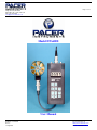
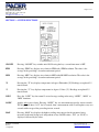
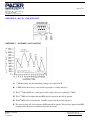
1450 First Ave.
Chippewa Falls, WI 54729
(800) 283-1141 or (715) 723-1141
Fax: (715) 723-7890
[email protected]
Page 1 of 12
Model DTA4000
User Manual
DTA4000 User Manual
Rev 1.0
11-Aug-2007
Pacer Instruments, Inc
www.pacer-instruments.com
Phone: 1-800-283-1141
1450 First Ave.
Chippewa Falls, WI 54729
(800) 283-1141 or (715) 723-1141
Fax: (715) 723-7890
[email protected]
Page 2 of 12
Warranty
This product is fully warranted against defective materials and/or workmanship for a period of one year
after purchase, provided it was not improperly used. For your protection, please use this product as soon as
possible. If returned, it must be securely wrapped, sent prepaid and insured to:
Pacer Industries, Inc.
1450 First Avenue
Chippewa Falls, WI 54729
PH: 715-723-1141
FX: 715-723-7890
Please include a note with name, address, telephone number and description of the problem. Although we
provide assistance on Pacer products both personally and through our literature, it is still the total
responsibility of the customer to determine the suitability of the product for use in their application.
This manual is provided by Pacer Industries without any kind of warranty. Precautions have been taken in
accurately preparing this manual; however, we neither assume responsibility for any omissions or errors that
may appear nor assume liability for any damages that result from the use of the products in accordance with
the information contained in the manual.
DTA4000 User Manual
Rev 1.0
11-Aug-2007
Pacer Instruments, Inc
www.pacer-instruments.com
Phone: 1-800-283-1141
1450 First Ave.
Chippewa Falls, WI 54729
(800) 283-1141 or (715) 723-1141
Fax: (715) 723-7890
[email protected]
Page 3 of 12
INTRODUCTION
Pacer’s model DTA4000 digital thermometer-anemometer is a versatile instrument for measuring and logging
air velocity and temperature of airflow from HVAC ducts or process air flow. Included are an RS232C output
port with 9-pin serial cable and an analog output with cable.
The heavy, all metal air velocity probe can be used for airstreams which have a wide range of humidity,
temperature and contaminants without compromising accuracy. The temperature sensor is a platinum resistance
element (RTD).
Features of the air velocity probe include choice of diameters, custom cable lengths, tolerance of temperatures
up to 210ºF (98.9ºC), and durability. Optional special-purpose temperature-only probes may be purchased from
factory.
SECTION 1 - SPECIFICATIONS
Range:
APT275 probe:
40 – 7800 FPM (0.2 - 40.0 MPS)
APT100 probe:
60 – 6800 FPM (0.3 – 35.0 MPS
Temperature:
-22º to 212ºF (-30º to 100ºC)
Temperature-only probes (optional):
-100º to 575˚F (-100º to 300ºC)
Accuracy:
Air Velocity:
±1.0% of reading ±1 digit
Temperature:
±0.2% of Reading ±1 digit
Resolution:
Air Velocity:
1 FPM or 0.01 MPS
Temperature:
0.2ºF or 0.1ºC
Response time:
Temperature:
Approximately 60 seconds
Operating temperature:
Instrument:
32º to 125ºF (0º to 50ºC)
Air velocity probe:
-4º to 210ºF (-20º to 98.9ºC)
Power supply:
9V alkaline battery (optional 9V
NiMH battery with charger)
Battery life:
Approximately 30 hours
Battery check:
Automatic low battery display
Data acquisition:
Storage capacity up to 999 double measurements of temperature and air velocity
with manual “SAVE”.
Data link:
Standard RS-232C at 1200 baud, including handshake signals CTS and RTS.
Display:
0.5” LCD, 4 digits
Weight:
21.9 ounces with probe
DTA4000 User Manual
Rev 1.0
11-Aug-2007
Pacer Instruments, Inc
www.pacer-instruments.com
Phone: 1-800-283-1141
1450 First Ave.
Chippewa Falls, WI 54729
(800) 283-1141 or (715) 723-1141
Fax: (715) 723-7890
[email protected]
Page 4 of 12
Dimensions:
Instrument:
7.5” x 3.2” x 1.2”
APT275 probe:
2 ¾” diameter
APT100 probe:
1” diameter
Options:
Model CG-3 charger:
PN 6043 NiMH battery/charger
Printer MD IMP2600:
PN 6233 DC/ PN 6238 AC power
Additional velocity probe: APT100 (1”) or APT275 (2 ¾”)
Extension cables:
PN 3831 (specify length)
Extra extension rod:
PN 5001 rigid, PN 5002 flexible
Special-purpose temperature probes:
PT201S:
PN 6301 GP immersion probe
PT202S:
PN 6303 air probe
PT203S:
PN 6304 surface probe
Included:
1 air velocity probe:
Choice, APT100 or APT275
3 pieces:
PN 5001 rigid extension rod
1 piece:
PN 5002 flexible extension rod
1 piece:
PN 3830 5’ air velocity cable
(attached to the APT100 probe)
1 piece:
PN 3843 5’ RS-232C cable
1 piece:
PN 3838 5’ analog output cable
1 piece:
9V alkaline battery
1 piece:
PN 6001 hard-shell carrying case
1 piece:
M2955 Operation manual
DTA4000 User Manual
Rev 1.0
11-Aug-2007
Pacer Instruments, Inc
www.pacer-instruments.com
Phone: 1-800-283-1141
1450 First Ave.
Chippewa Falls, WI 54729
(800) 283-1141 or (715) 723-1141
Fax: (715) 723-7890
[email protected]
Page 5 of 12
SECTION 2 – SWITCH FUNCTIONS
ON/OFF
Pressing “ON/OFF” key switches unit ON. Pressing the key a second time turns it OFF.
FPM
Pressing “FPM” key displays air velocity in FPM with 1 FPM resolution. The value is the
average of the preceding 2 second measurement period.
MPS
Pressing “MPS” key displays air velocity in MPS with 0.01 MPS resolution. The value is the
average of the preceding 2 second measurement period.
ºF
Pressing the “ºF” key displays temperature in degrees Fahrenheit (ºF). Readings are updated 2.5
times/second.
ºC
Pressing the “ºC” key displays temperature in degrees Celsius (ºC). Readings are updated 2.5
times/second.
2/SEC
Press the “2/SEC” key for normal 2 second average readings after using “16/SEC”, “MAX” or
“MIN” functions.
16/SEC
Applies only to air velocity: Pressing “16/SEC” key sets measurement period to sixteen seconds.
The display will show “16 S” for 16 seconds, then a measurement value. It will update every two
seconds with average of the preceding sixteen seconds.
MAX
Pressing “MAX” key displays the highest reading since turn-on for the parameter being
measured in the units being used, independent of any SAVED values. “H 2” (or “H 16”) is
displayed, followed by the value.
DTA4000 User Manual
Rev 1.0
11-Aug-2007
Pacer Instruments, Inc
www.pacer-instruments.com
Phone: 1-800-283-1141
1450 First Ave.
Chippewa Falls, WI 54729
(800) 283-1141 or (715) 723-1141
Fax: (715) 723-7890
[email protected]
Page 6 of 12
MIN
Pressing “MIN” key displays the lowest reading since turn-on for the parameter being measured
in the units being used, independent of any SAVED values. “L 2” (or “L 16”) is displayed,
followed by the value.
NOTE: The “- 2” or “- 16” above refer to the averaging period being used. Press “2/SEC” key to
clear MAX/ MIN mode. See APPENDIX C for description of algorithm that saves MAX/MIN.
SAVE
Pressing “SAVE” during a measurement mode will store a data double consisting of the air
velocity and temperature values being measured at that instant, for a maximum of 999 data
doubles.
DUMP
Pressing the “DUMP” key will transfer the SAVED measurements to a connected printer or PC.
Measurements will be retained for at least 1 year or until memory is cleared by holding the
“DUMP” key when turning unit on.
ANALOG OUTPUT Analog outputs for temperature and airspeed provide 0-2V FS. See APPENDIX G for
details.
SECTION 3 – OPERATION
NOTE: Unit should be “OFF” before changing batteries or attaching cables.
1) Remove battery compartment lid and insert battery; replace lid.
2) Attach the probe cable by carefully aligning the keyway, inserting the connector and turning the
collar to tighten. (See APPENDIX A for unit’s connector wiring diagram).
3) Press the “ON/OFF” key to turn unit ON. The display will show all elements followed by the
remaining battery capacity (“8.2” means the battery is at 8.2V), followed by “P” and a 3 digits
(i.e. “P025 which means 24 data points are stored). If the “DUMP” key in held when pressing
“ON/OFF” key at turn-on, the data point memory will be cleared.
NOTE: If the battery drops below 6V during use, an “L” shows in the leftmost digit implying a
new (or recharged) battery is required.
4) To view airspeed, press “FPM” or “MPS” key to display desired units. Place probe in the air
stream with the axis or direction arrow (if present) in the direction of airflow. To calculate
volume flow rate see APPENDIX D.
5) To view temperature, press “ºF” or “ºC” key and place probe in area to be measured. See
APPENDIX E if “E-xx” (error xx) is displayed.
6) To SAVE the displayed reading (see SAVE in SECTION 2), press the “SAVE” key.
7) To correctly measure the air velocity from a large duct, set unit to “16/SEC” mode and move
probe about the area of the opening. After 16 seconds, the unit will display the average velocity
for the preceding 16 seconds, updating after that every 2 seconds by adding the latest 2 second
measurement and dropping the oldest 2 second measurement.
DTA4000 User Manual
Rev 1.0
11-Aug-2007
Pacer Instruments, Inc
www.pacer-instruments.com
Phone: 1-800-283-1141
1450 First Ave.
Chippewa Falls, WI 54729
(800) 283-1141 or (715) 723-1141
Fax: (715) 723-7890
[email protected]
Page 7 of 12
8) To get maximum readings since turn-on, press “MAX” key; to get minimum readings, press
“MIN” key. For explanation of the displayed views, see “MAX” and/or “MIN” paragraph in
SECTION 2. For explanation of algorithm that calculates MAX and MIN see APPENDIX C.
9) To dump data to a PC, see SECTION 4.
A.
SECTION 4 – INSTRUCTIONS FOR DUMPING MEMORY
For use with Win 95, 98, NT4, 2000 and Win XP using resident HyperTerminal (See APPENDIX F for data
explanation)
Open HyperTerminal
1) Click “Start” button on task bar.
2) Highlight “Programs”
3) Highlight “Accessories”
4) Highlight “Communications” or open “HyperTerminal” folder (Win 95)
5) Choose and open “HyperTerminal” program
B. The “Connection Description” window comes up
1) Under “Name” type: “Pacer”
2) Choose (click on) an icon or accept default
3) Click “OK”
C. The “Connect To” or “Phone Number” (Win 95) window comes up
1) In “Connect using:” box select the Com port you will use (probably “Com1” if not presently in
use)
2) Click “OK”
D. The “Com() Properties” window comes up
1) Set “Bit per second:” to “1200”
2) Set “Data bits:” to “7”
3) Set “Parity:” to “odd”
4) Set “Stop bits:” to “1”
5) Set “Flow control:” to “Hardware”, click “Apply” and “OK”
6) Under “File” menu click “Properties”
7) In “Pacer Terminal Properties” window click “Settings” tab
8) Click “ASCII Setup…” box at bottom right
9) Check “Force incoming data to 7-bit ASCII” under “ASCII Receiving”
10) Click “OK” in “Properties” windows, then click “Save” under “File” menu
E. Under the “Transfer” menu select “Capture Text…”
1) The “Capture Text” window appears
2) Type in a name for the file you want the data placed into
3) Click “Start”
F. Connect the cable from the data logger
1) Connect the RS232 cable to the serial port.
2) Turn on the DTA4000
G. Transfer the data
1) Press the “ºF/ºC” key on the data logger
2) Press the “DUMP” key
DTA4000 User Manual
Rev 1.0
11-Aug-2007
Pacer Instruments, Inc
www.pacer-instruments.com
Phone: 1-800-283-1141
1450 First Ave.
Chippewa Falls, WI 54729
(800) 283-1141 or (715) 723-1141
Fax: (715) 723-7890
[email protected]
Page 8 of 12
3) The flowing data will now appear in the “Pacer – HyperTerminal” window
4) Wait until the data has finished transferring
5) Highlight “Capture Text” under the “Transfer” menu
6) Select “Stop”
7) The data is now in the file named in step E2
H. Select “Exit” under the “File” menu
1) Note message “You are currently connected. Are you sure you want to disconnect now?”
2) Click “Yes”
3) If the message “Do you want to Save Session ()?” appears, click “Yes”
4) Your data is now downloaded and saved
I. Instructions for moving transferred data into an Excel spread sheet
1) Find and double-click the file name of the data file you created in G above.
2) The “Open With” window should appear
3) Select “Notepad” and open the file
4) Select any amount of data and execute “Copy”
5) Open a new Excel spreadsheet, select “Paste”
6) The A column now contains the data.
J. Split data into temperature and air velocity
1) Under “Data” menu select “Text to columns…” and click “Next” in the open window
2) Follow the directions to separate the data
3) After the column breaks are in place, click “Finish”
APPENDIX A – CONNECTOR DIAGRAM
DTA4000 User Manual
Rev 1.0
11-Aug-2007
Pacer Instruments, Inc
www.pacer-instruments.com
Phone: 1-800-283-1141
1450 First Ave.
Chippewa Falls, WI 54729
(800) 283-1141 or (715) 723-1141
Fax: (715) 723-7890
[email protected]
Page 9 of 12
APPENDIX B – RS-232C CABLE PINOUTS
APPENDIX C – MAX/MIN CALCULATIONS
A) 1st MAX reading; also first minimum reading, to be replaced at B.
B) 1st MIN at B is the lowest yet and will be registered as velocity increases.
C) This 2nd, higher MAX at C will register as the velocity decreases, replacing 1st MAX.
D) This 2nd MIN at D is higher than the MIN already registered and will be ignored.
E) This 4th MIN at E is lower than the 1st MIN, registered at B, and will replace it.
F) The zero crossing at F does not form a MIN and will be ignored. This protects against false MIN
readings when the probe is withdrawn from the air stream.
DTA4000 User Manual
Rev 1.0
11-Aug-2007
Pacer Instruments, Inc
www.pacer-instruments.com
Phone: 1-800-283-1141
1450 First Ave.
Chippewa Falls, WI 54729
(800) 283-1141 or (715) 723-1141
Fax: (715) 723-7890
[email protected]
Page 10 of 12
APPENDIX D – AIRFLOW VOLUME CALCULATIONS
Theory:
To calculate cubic feet per minute (CFM) from a measured air velocity (FPM), you need the
calculated cross-sectional area of the airflow stream:
Volume Flow (CFM) = Velocity (FPM) X Area (sq ft).
In rectangular ductwork this cross sectional area equals the Width times the Height.
W x H=A (cross-sectional area)
In circular ductwork this cross section area equals the radius squared times π (3.14).
Example:
Step 1:
Step 2:
Step 3:
R x R x 3.14=A (cross-sectional area)
To convert an area calculated in square inches to an area calculated in square feet (which is
required for the Volume Flow equation above) divide by 144: (area in sq in.)/144 = (area in sq
ft.).
The air duct is rectangular, the width is 24 in. and the height is 12 in. The air velocity reading
through the duct is 450 FPM. Calculate the Volume Flow.
Cross-sectional area = 24 in. x 12 in. = 288 sq in.
288 sq in /144 = 2 sq ft.
Volume flow = Air Velocity x Area, therefore, Volume flow rate = 450 FPM x 2 sq ft. = 900
CFM.
APPENDIX E – ERROR CODES
“E-02” Data logger is filled to maximum capacity of 999 SAVED measurements.
“E-03” Storage is empty. No measurements have been SAVED since last time memory was cleared.
“E-04” No communication is occurring through the RS232 data link with the printer or PC.
“E-08” Temperature is below range (<-99.9 ºC or ºF).
“E-09” Temperature is above range (>300.0ºC or >575ºF).
“E-XX” Error codes of 50 or higher are internal errors. In this case, contact the manufacturer.
DTA4000 User Manual
Rev 1.0
11-Aug-2007
Pacer Instruments, Inc
www.pacer-instruments.com
Phone: 1-800-283-1141
1450 First Ave.
Chippewa Falls, WI 54729
(800) 283-1141 or (715) 723-1141
Fax: (715) 723-7890
[email protected]
Page 11 of 12
APPENDIX F – DATA COMMUNICATIONS
The instrument provides an RS-232 data output. The voltage levels are plus and minus 9V. A
voltage of +9V represents a space (logical “0”). A voltage of -9V represents a mark (logical “1”).
The protocol is: 1 start bit, 7 data bits, 1 odd parity bit, 1 stop bit, ASCII data format, 1200 baud.
Sample data items:
001 76.9 dgF 2385 FPM
002 24.9 dgC 12.12 MPS
RS-232 Data Pin-out Connections:
Signal
4P-Female
Gnd
1
Transmit - TXD
2
Clear/send-CTS
3
Ready/send-RTS
4
9-pin Printer
5
7
2
2
7
5
8
4
After pressing the “DUMP” key an RTS (1) appears on the RS-232 cable. The PC or printer must
respond with a CTS (0) within 1 second; if not, an “E-04” shows and DUMP mode ends. If handshaking occurs, ASCII data transfers at 1200 baud. Each data line (record) is terminated with a
CR (carriage return) and LF (line feed). At the end of transmission the instrument generates an
EOF (end of file) character. The PC can then return to the OS.
APPENDIX G – ANALOG OUTPUTS
TEMPERATURE:
Range: -148º to 572ºF (-100º to 300ºC)
Scale: 360ºF/V (200ºC/V)
Offset: -0.4111V for ºF; -0.5V for ºC
Example: For Vout = 1V:
ºF temp is: (1-0.4111)V x 360ºF/V = 212ºF
ºC temp is: (1-0.5)V x 200ºC/V =100ºC
AIR VELOCITY:
Range: 0 to 7935 FPM (0 to 40.31 MPS)
Scale: 3967.5FPM/V (20.155 MPS/V)
Example: For Vout = 1V:
Velocity in FPM: 1V x 3967.5FPM/V =3967.5FPM
Velocity in MPS: 1V x 20.155MPS/V =20.155MPS
DTA4000 User Manual
Rev 1.0
11-Aug-2007
Pacer Instruments, Inc
www.pacer-instruments.com
Phone: 1-800-283-1141
1450 First Ave.
Chippewa Falls, WI 54729
(800) 283-1141 or (715) 723-1141
Fax: (715) 723-7890
[email protected]
Page 12 of 12
Notes:
DTA4000 User Manual
Rev 1.0
11-Aug-2007
Pacer Instruments, Inc
www.pacer-instruments.com
Phone: 1-800-283-1141


![PathoDx Strep Grouping [FR]](http://vs1.manualzilla.com/store/data/006482237_1-0696bde666d7c2388790b287f1e15786-150x150.png)