1
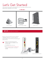
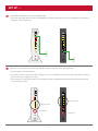
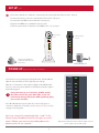
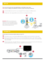
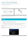
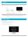
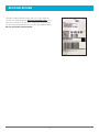
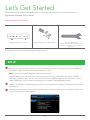
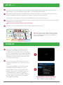
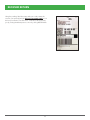
SELF-INSTALLATION GUIDE
Welcome to FrontierTV
You are just a few quick connections away from the most amazing TV
experience you’ve ever had. The colors are stunning and the sound is
astonishing.
Just follow the enclosed step-by-step instructions, and you’ll get hundreds
of all digital channels, tons of HD channels and thousands of On Demand
titles at your fingertips. All in crystal clear lifelike clarity.
This guide will make it quick and easy to replace your Wireless Router and
add or replace a Wireless TV Receiver.
WIRELESS ROUTER REPLACEMENT.................................................................. 3
WIRELESS TV RECEIVER........................................................................................ 9
WIRELESS RECEIVER REPLACEMENT........................................................15
WIRED RECEIVER REPLACEMENT..............................................................20
WIRELESS ROUTER REPLACEMENT
Let’s Get Started
These instructions will guide you through the process of replacing your Wireless Router.
Approximate installation time: 35 minutes
In the box:
Voice Line Splitter
Battery Backup Unit (BBU)
Wireless Router
PHONE LINE
3
1
• Set the BBU aside; do not use.
2
CAL ETHERNE
T
4
• Unplug the existing Wireless Router
and Battery Backup Unit (BBU) from the
electrical outlet.
RESET
• Refer to Equipment Return and Recycling
on page 8 of this guide for recycling of
the BBU.
POWER
A
PHONES
Begin by setting up the Wireless Router and then
establishing each service. You will not have TV,
Internet and Voice service while you’re replacing your
Wireless Router.
LINES 1 & 2 AU
SET UP Approximate time: ten minutes
Existing Wireless Router
4
1
Replacement Wireless Router
SET UP cont.
B
• Stand the new Router next to the existing Router.
3
2
PHONES
POWER
RESET
1
CAL ETHERNE
T
4
PHONE LINE
LINES 1 & 2 AU
• Disconnect the data cable from the existing Wireless Router’s green phone line port and plug it into the green
data port on the new Router.
• Remove one connection at a time from the Ethernet (yellow) ports of the existing Router.
• Connect them to the new Router.
• If you have a cable connected to the Coaxial port of your existing Router, disconnect the cable and connect it to
your new Router as tightly as possible.
PHONES
PHONE LINE
LINES 1 & 2 AU
• The connectors on the back panel of the new Router may be arranged differently, but the names, shapes and
colors will be the same.
3
1
2
Ethernet Ports
Coaxial Port
Coaxial Port
RESET
CAL ETHERNE
T
4
Ethernet Ports
POWER
C
5
SET UP cont.
D
• Disconnect the phone cord that is connected to the existing Router’s Phone Lines 1 & 2 port.
• Connect the phone cord to the new Router’s Phone Lines 1 & 2 port.
• Connect the new BBU to the new Router’s power port.
• Plug the new BBU into a standard electrical outlet.
Phone Lines
1&2
Phone Lines
1&2
A Voice Line Splitter is
required if you have two
Voice lines.
3
2
POWER
RESET
1
CAL ETHERNE
T
4
PHONE LINE
PHONES
LINES 1 & 2 AU
• Turn the power switch on the back of the BBU to the “on” position.
Battery Backup Unit
POWER UP Approximate time: 15 minutes
Power
Your Router is now powering up. During this time, the Broadband
light will turn red and the Power light may turn orange.
Wait up to 15 minutes for the indicator lights for Broadband and
Service to turn solid green and the Local Ethernet indicator light to
start blinking green.
During this time (up to 15 minutes), do NOT unplug
the power cord or the green data cable, as this can
permanently damage the Router AND significantly delay
your service activation.
If the Broadband and Service lights do not turn solid green or
continue to blink after 15 minutes, see the Having Trouble? section
on page 13 of this guide.
You have successfully completed steps 1 and 2 if the
Router Power, Broadband and Service lights are solid
green. Reboot your receivers by holding down the
power button for ten seconds.
6
Ethernet
Wireless
Home PNA
Phone 1
Phone 2
Broadband
Service
Replacement Wireless Router indicator lights on front
panel. Lights may vary with set up.
GO Wi-Fi Approximate time: ten minutes
You will need to complete this step in order to reestablish your Wi-Fi connections. Example: If you have set a Custom
SSID or Wireless Network Key, the replacement Wireless Router will be reset to defaults and any custom settings would
need to be reconfigured.
Write down your new Network Name (SSID) and new Wireless Network Key (WPA) to configure a Wi-Fi device. This
information is on the side of your Wireless Router. The Network Name consists of “2WIRE” and/or “Frontier” plus the last
three digits of the Wireless Router’s serial number. Be sure to record this information in the form on this page.
Now configure your new wireless network:
1. G
o to your computer’s “Wireless Network Settings”
and refresh the network list.
SN::
2. S
elect your Network Name (SSID) from the list.
You may need to scroll through the list to find your
SSID.
3. E
nter the ten-digit Wireless Network Key (WPA) in
the Password field to connect to your network.
For
Fo
or Advanced
Advanced Configuration:
Co
onfiguration: http://192.168.1.254
System
Sy
ystem
mP
Passw
Password:
word::
Mac
Address:
M
ac A
dd
dress:
Wireless
W
Wirele
esss Net
Network
twork Key::
WPA
Network Name (SSID)
2
W
I
R
E
Ten-digit Wireless Network Key (WPA)
4. C
onnect all your Wi-Fi devices with the new SSID
and new Wireless Network Key.
HAVING TROUBLE?
Many issues can be resolved with these simple steps:
1. Check your connections.
Ensure all cables and cords are connected properly and securely. Cables usually make an audible click when secure.
2a. Check power.
If you have power and the Router is turned on, the Power light on the front of your Wireless Router will have a green
light. If no lights are on:
1. Ensure the Router is plugged into a working electrical outlet.
2. Ensure power cable on the back of the Router is pushed in firmly.
At this point, your Power light on the front should be green; if not, try another phone outlet and remove any power
strips.
2b. Power light green; Broadband/Service lights red or blinking.
1. If after 15 minutes your Broadband/Service light is not green, check that the green cable or
coaxial cable is connected securely.
2. If cables are secure, power down the Wireless Router by holding the red-circled reset button
located on the back of the Router for 15 seconds and wait an additional ten minutes.
7
Reset button
HAVING TROUBLE? cont.
SPECIFIC ISSUES
My Power indicator light turns orange during the power up sequence.
Don’t worry. This is a normal part of the power up sequence—just remember not to unplug the power cord or data cable depicted
in green in this guide when the light is still orange. At the end of the sequence, the Broadband and Service indicator lights will be
solid green.
Every time I try to browse a Web page, I get a message saying “Detecting Proxy Settings.”
In Internet Explorer under Tools > Internet Options > Connections > LAN Settings, uncheck any checked boxes and click OK.
My screen is snowy/black or indicating No Signal.
Please make sure to select the appropriate TV input (source) in the TV configuration. Consult your TV manual for details.
I followed the instructions in this guide, but my Wireless Router is still not working.
Reset the Router by pressing and holding the red-circled reset button located on the back of the Router for 15 seconds. Check all
cable connections to make sure they are secure.
My receivers/TV are not responding.
Confirm that the Broadband and Service lights are solid green on the Router. If they are, power down the affected receivers: Hold
the power button down for ten seconds and release, then wait five minutes.
I don’t have a dial tone.
Check all cables and cords to ensure they are connected properly and securely. Go to step D and verify your setup.
Check to make sure you have a working phone jack.
EQUIPMENT RETURN AND RECYCLING
Returning your Wireless Router.
The Router is to be returned in the box provided and affix the
UPS label provided.
Recycling/disposing of your Battery Backup Unit.
For battery replacement and recycling/disposal information,
visit their Web site at
www.belkin.com/us/gatewaybattery.
8
WIRELESS TV RECEIVER
Ready to install your Wireless TV Receiver?
Let’s Get Started
Approximate installation time: 20 minutes
What’s in the box?
To install your Receiver, you will need:
POWER
Wireless TV Receiver
Wireless Access Point
Wireless TV Receiver power cord (two parts)
Ethernet cable
Remote control
Wireless Access Point power cord
HDMI and coaxial cable
What else do you need?
Your existing Wi-Fi Router (actual model may vary)
Your TV’s user manual
Note: Additional cable(s) (HDMI, RCA, Coaxial, etc.) that connect(s) TV with Wireless Receiver not included.
10
SET UP
First, you need to connect your existing Wi-Fi Router to the Wireless Access Point.
NOTE: If you are adding a Second Wireless TV Receiver, skip this step and go to Power Up.
A Connect the Wireless Access Point to your existing Wi-Fi Router using the yellow Ethernet cable.
B Use the power cord to plug the Wireless Access Point into a working electrical outlet.
A
B
Remember: Make sure you have an open
Ethernet port on your existing Wi-Fi Router,
and be sure to leave existing cables plugged
in. No open port? You’ll need to purchase an
Ethernet hub with additional ports.
Wi-Fi Router
(back)
Wireless Access Point
(back)
POWER UP
The next step is to connect your Wireless Receiver to your TV.
A Connect the receiver to your TV with an HDMI cable (not included). You may also use RCA or Coaxial cables.
ower up your TV and go to the Input Source screen. Your TV manufacturer’s remote control may have an Input
B Pbutton
that will take you there. Select the Source you used in the previous step. For instance, if you used an HDMI
cable, select HDMI.
Put the two-part power cord together. Then use it to plug the receiver into an electrical outlet, and it will power up
C automatically. After about a minute, you’ll receive additional onscreen instructions.
A
B
C
11
PAIR UP
Now let’s get your Wireless TV Receiver and Wireless Access Point talking to each other.
Follow the instructions on your TV screen. A On the front of your new receiver, press the OK button.
Your TV screen should look like this.
Note: Pairing occurs quickly. To ensure you have proper signal strength, there should be at least three LED green bars
lit up on the receiver.
ress the Wi-Fi Protected Setup (WPS) button on the front of the Wireless Access Point, and you’ll see a fastB Pblinking
LED light up on the unit.
Your TV screen should look like this.
hen you see a green antenna icon on your TV screen, or a green LED on the front of your receiver, you’ve
C Wpaired
successfully. It may then take a few more minutes before live TV appears.
Your TV screen should look like this.
Great job. The initial steps are over—now it’s time to enjoy your TV.
12
HAVING TROUBLE?
If you see a red antenna:
1. D
isconnect your Wireless TV Receiver from its current location.
2. P
lug the receiver into a power cord that is closer to the Wireless Access Point.
3. G
ive it a minute and then repeat the last two steps on “Pair Up.”
REMOTE CONTROL INFORMATION
New Frontier customers or current customers adding a new receiver will need to program the new remote control.
Programming instructions are available online at Frontier.com/HelpCenter and in the remote control user guide
packaged with the remote control.
13
ADDING A SECOND WIRELESS TV RECEIVER
A Complete the installation of the first TV Receiver.
B Repeat steps in the instructions for Power Up and Pair Up sections in this guide with the second TV Receiver.
14
WIRELESS RECEIVER REPLACEMENT
Let’s Get Started
These instructions will guide you through the process of replacing your wireless TV receiver.
Approximate installation time: 15 minutes
Gather materials needed for set up:
POWER
Replacement Frontier receiver
Replacement power cord (two parts)
The appearance of your receiver and power cord may differ from above pictures.
Equipment return instructions are on page 19 of this guide.
SET UP
efore you begin, you’ll want to make note of your current screen resolution setting. To do this, press MENU on
A Byour
remote control. The Menu screen should display on your TV.
Note: If your receiver cannot display the menu, skip this section.
From the Menu screen, use the arrows on your remote control to select “OPTIONS,” then select “SYSTEM
OPTIONS,” and press “OK.” Now choose “TV screen resolution (HD/SD)” and press the “OK” button on your
remote. Make note of your current Screen Resolution. For example, 720p High Definition (HD).
nplug your existing receiver and remove the power cord. Set this power cord aside, you will not need to use this
B Ucord
anymore.
stack your new receiver on top of your existing receiver. This will allow you to reconnect the cables one at
C Ca arefully
time, keeping them all in the right place.
16
SET UP cont.
he back of your receiver and the connections may
D Tvary
depending upon the model. If the connectors
are in different places, just follow the names, shapes
and colors, as they will all be the same.
VIDEO OUT
his illustration of the existing receiver shows various
E Tconnection
possibilities. You will only need to use one
Pb
NETWORK
Video
Y
Audio
Pr
VIDEO IN
Existing
HDMI
NETWORK
New
Power
Cord
S-Video
Optical
of the connections (HDMI, Component, Composite or
Coaxial) to connect your receiver to the TV.
POWER
HDMI
Replacement
Pb
Y
Pr
S-Video
S- eo
Video
Audio
USB
VIDEO OUT
USB
POWER
The illustration of the replacement receiver shows
HDMI, which is the preferred connection.
ORANGE BOX:
shows Component video connection (red, green, blue) and
RCA audio connection (red, white). Yellow connector is not
used in this case.
fter you have successfully completed your wireless
F Areceiver
connections, plug your new power cord
RED BOX:
shows Composite video (yellow) and audio (white
and red) connections.
BLUE BOX:
HDMI (preferred connection)
Note: If using coaxial connection, apply sufficient force to tighten
the connectors past “finger tight.” Failure to properly tighten this
connection will degrade the signal and can cause intermittent or
continuous video problems.
into your wireless receiver first, and then into the
electrical outlet. Your new receiver will power
up automatically. Please wait for the onscreen
instructions to appear on your TV. Do not turn off the
TV or receiver during this process.
Do not reuse the power cord from your old
receiver.
POWER UP
Now let’s get your Wireless TV Receiver and Wireless Access Point talking to each other. Follow the instructions on
your TV screen. A On the front of your new receiver, press the OK button.
the Wi-Fi Protected Setup (WPS) button on
B Ptheressfront
of the Wireless Access Point, and you’ll
see a fast-blinking LED light up on the unit.
Your TV screen should look like this.
Note: Pairing occurs quickly. To ensure you have proper signal
strength, there should be at least three LED green bars lit up on the
receiver.
17
Your TV screen should look like this.
POWER UP cont.
hen you see a green antenna icon on your TV screen or a green LED on the front of your receiver, you’ve paired
C Wsuccessfully.
It may then take a few more minutes before live TV appears.
Your TV screen should look like this.
Congratulations—you are connected! Press “Guide” to start watching TV.
Great News! Continue to use your existing remote control—it will work with your new receiver. To review
programming instructions for your remote control, visit frontier.com/helpcenter.
HAVING TROUBLE?
If you see a red antenna:
1. Disconnect your Wireless TV Receiver from its current location.
2. M
ove the Receiver closer to the Wireless Access Point.
Now reconnect it to another power outlet.
3. Give it a minute and then Power Up and Pair Up.
See Equipment return instructions on the next page.
18
RECEIVER RETURN
Using the packing label that came with your order, return the
receiver you replaced and the old two-part power cord as-is in
the box provided to The UPS Store®. Find the location nearest
you by visiting www.theupsstore.com or by calling 800.789.4623.
Do not return your remote control.
19
WIRED RECEIVER REPLACEMENT
Let’s Get Started
These instructions will guide you through the process of replacing your FrontierTV receiver with a new receiver.
Approximate installation time: 15 minutes
Gather materials needed for set up:
Replacement Frontier receiver
Replacement power cord (two parts)
Not included: wrench
You may also need a 7/16-inch wrench to loosen
the existing coaxial cable connection on the back
of the receiver.
The appearance of your receiver and power cord may differ from above pictures.
SET UP
efore you begin, you’ll want to make note of your current screen resolution setting. To do this, press MENU on
A Byour
remote control. The Menu screen should display on your TV.
Note: If your receiver cannot display the menu, skip this section.
From the Menu screen, use the arrows on your remote control to select “OPTIONS,” then select “SYSTEM
OPTIONS,” and press “OK.” Now choose “TV screen resolution (HD/SD)” and press the “OK” button on your
remote. Make note of your current Screen Resolution. For example, 720p High Definition (HD).
nplug your existing receiver and remove the power cord. Set this power cord aside, you will not need to use this
B Ucord
anymore.
stack your new receiver on top of your existing receiver. This will allow you to reconnect the cables one at
C Ca arefully
time, keeping them all in the right place.
21
SET UP cont.
he back of your receiver and the connections may vary depending upon the model. If the connectors are in
D Tdifferent
places, just follow the names, shapes and colors, as they will all be the same.
his illustration of the existing receiver shows various connection possibilities. You will only need to use one of the
E Tconnections
(HDMI, Component, Composite or Coaxial) to connect your receiver to the TV.
The illustration of the replacement receiver shows HDMI, which is the preferred connection.
fter you have successfully completed your receiver connections, plug your new power cord into your receiver first,
F Aand
then into the electrical outlet.
Do not reuse the power cord from your old receiver.
G Continue to use your existing remote control—it will work with your new receiver.
Pb
Y
L
R
New
Power
Cord
TO WALL
TO TV
(VIDEO OUT) (VIDEO IN)
Replacement
NETWORK
USB
Pr
Pb
S-VIDEO
VIDEO
OUT
Y
AUDIO
OUT
L
OPTICAL
POWER
Note: If using coaxial connection, apply sufficient force to tighten
the connectors past “finger tight.” Failure to properly tighten this
connection will degrade the signal and can cause intermittent or
continuous video problems.
R
TO TV
(VIDEO OUT)
TO WALL
W
(VIDEO IN)
Existing
NETWORK
YELLOW BOX:
shows Network connection
USB
Pr
S-VIDEO
VIDEO
O
OUT
ORANGE BOX:
shows Component video connection (red, green,
blue) and RCA audio connection (red, white).
Yellow connector is not used in this case.
AUDIO
DIO
OUT
OPTICAL
RED BOX:
shows Composite video (yellow) and audio
(white and red) connections.
POWER
BLUE BOX:
HDMI (preferred connection)
POWER UP
new receiver will power up automatically.
A YItour
may take several minutes for this process to
complete. Do not turn off the TV or receiver during
this process. When the process is finished, the LINK
light will turn green. If the light doesn’t turn green,
unplug the receiver from the electrical outlet, wait
15 seconds, and try again.
A
you can set your TV screen resolution. If you
B Now
noted your settings earlier, you can use those as a
reference.
To do this, press MENU on your remote control.
The Menu screen should display on your TV.
B
From the Menu screen, use the arrows on your
remote control to select “OPTIONS,” then select
“SYSTEM OPTIONS,” and press “OK.” Now
choose “TV screen resolution (HD/SD)” and press
the “OK” button on your remote. For example,
720p High Definition (HD).
Congratulations—you are connected!
Press “Guide” to start watching TV.
22
RECEIVER RETURN
Using the packing label that came with your order, return the
receiver you replaced and the old two-part power cord as-is in
the box provided to The UPS Store®. Find the location nearest
you by visiting www.theupsstore.com or by calling 800.789.4623.
23