1
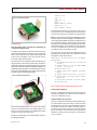
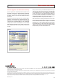
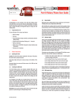
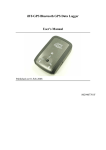
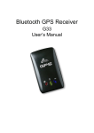
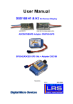
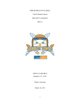
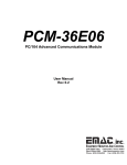
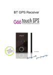
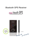
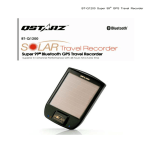
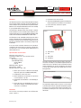
website:
6175 LONGBOW DRIVE, SUITE 200
USA
BOULDER, COLORADO
sparkfun.com
zip code:
Sharing
1 2 . 2 1 . 2 0 0 7 Ingenuity
80301
303
284.0979 [ general ]
443.0048
P
F
ÜberTracker User Guide
W W W. S P A R K F U N . C O M
Overview
1) Power Switch, turns unit on and off.
The ÜberTracker represents a merger of GPS and Cellular technologies
into one package capable of real-time asset tracking. GPS fixes are
taken according to a user specified interval, then reported via email or
GPRS to the user’s designated email address or web server according
to a user specified number of logs per report.
2) Status LED. Red during GPS operations, flashing green
during cell operations, blue indicates successful report.
The ÜberTracker is designed to work with a 6V input, or between
8V and 14V with the use of the included regulator module for use in
automotive applications. It uses the Telit GM862 Quad GSM cellular
module and the US Globalsat EM406 GPS SiRF 3 GPS module.
3) Power cable. Red is +6V, black is negative.
4) Cell antenna.
Figure 1
The ÜberTracker is FCC and PTCRB certified. Use of this device
requires a SIM card with an active AT&T Wireless® data account,
preferably an unlimited account to avoid the possibility of excessive
data fees. An unlimited account is not necessary, though we do
recommend it.
If the user wishes to alleviate themselves of the hardware,
configuration and network support of operating an ÜberTracker,
we invite them to visit our tracking partner TRACK America at
www.trackamerica.net.
Specifications and Features
Dimensions: 4.55”x3.30”x1.25”
Input Voltage: 6V (Max 7.2V), or 8V to 14V with converter
Current Draw:
GPS operations: 160 mA
Cellular GPRS Operations:
Average: 400mA
Peak: 2A
GPRS Output Power: 1W peak
GPS Sensitivity: -158dBm
Operating temperature: +80 to –30C
1) Able to report via email in 3 different formats: Google
Maps links, regular text and NMEA standard (RMC)
A) Power Switch
B) LED
C) Power Cable
D) Cell Antenna
The power converter (shown in Figure 2) takes its input from a
12V source on the white (+12V) and black (negative) leads, and
should connect to the ÜberTracker (red to red and black to black)
with the included wire nuts. For noise considerations, the converter
is of linear type, and thus may become slightly warm to the touch
during operations.
Figure 2: Power Converter
2) Configurable to send to a web server
3) Able to take GPS fixes as frequently as one per minute
or as infrequently as 1 per day
4) Configurable to send between 1 and 6 GPS logs per
report
5) Device will retain up to 240 individual logs in areas of
poor cellular coverage, and will report them when a
connection is re-established
Hardware
The Programming adapter (shown in Figure 3) is used for setting
up the ÜberTracker with your configuration and firmware upgrades.
It plugs into a 6-pin female header inside the ÜberTracker case,
accessible by removing the four screws from the top of the
ÜberTracker.
There are only a few things to observe on the ÜberTracker
(shown in Figure 1):
ÜberTracker_UG_v071221
1/4
12.21.2007
Figure 3: Programming Adapter
ÜberTracker User Guide
Interval = 10
Logs = 3
GPRS_fail = 0
Mode = 1
Remote Address = Blank
Remote Port = 0
Email Address = Blank
The ÜberTracker will now wait for 5 seconds for the user to press
their space bar to access the configuration menu. If the space bar
is not pressed in that time, the unit will go into regular operation.
Configuration
Note: Read this entire section before attempting to
configure the ÜberTracker.
To configure the ÜberTracker, you will need a computer running a
terminal emulator (Hyperterminal, Teraterm, etc), a serial cable (or
USB to serial), and you will need to provide the ÜberTracker with
a power source. If installing in a car or truck, it may be easiest to
do this with a laptop inside the vehicle.
First, remove the 4 screws that retain the top of the ÜberTracker case
and pull off the top. In the corner by the power switch, you will find a
small female header. Plug the programming adapter into this port as
shown. Figure 4 shows the switch on the programming adapter in the
programming position (toward the center, indicated by an arrow and
the text “prog”). For configuration, set the switch in the other direction
(toward the outside of the programming adapter).
Note: It is important that the ÜberTracker DOES NOT run regular
operations with the serial adapter plugged in. The COM port that is
used is shared with the GM862 cell module. Port conflicts will occur
if the programming adapter is plugged in and the cellular module
becomes active, as indicated by the flashing green status LED.
Under default conditions, the user would have to wait 30 minutes
for this to occur. Nonetheless, the user must be aware that this is
a possibility and take care to avoid the condition.
At this point, press the space bar and the configuration menu will
be displayed in the terminal window (exact firmware version and
date subject to change without notice):
ÜberTracker, Firmware Version 1.0, 11/29/07,
WAAS Enabled
1)Change GPS lock interval, currently 10
minutes
2)Change number of logs per Email/GPRS
report, currently 3
3)Reset failure log
4)Change remote server address, currently
Blank
5)Change remote server port, currently 0
Figure 4: ÜberTracker with top off
6)Change mode, currently email, Google
Maps links
7)Change email address, currently Blank
9)Save and exit
Description of the Configuration Menu Items
1) Change GPS lock interval
Pressing “1” will allow you to change the frequency with which the
ÜberTracker gets GPS fixes. This number is in minutes, and can be
set from 1 to 1440 minutes (1 day).
2) Change number of logs per report
Connect the programming adapter to your serial cable and your
cable into your computer. Open up your terminal emulator to the
port you’ve connected to and set it up for 38400 baud, 8-bit data,
no parity, one stop bit and no flow control.
Now turn on your ÜberTracker. In the terminal window, you will see
the following information:
ÜberTracker_UG_v071221
Pressing “2” will allow you to change the number of GPS fixes that
are contained within each report, between 1 and 6. This setting
combined with the lock interval setting will determine how often
the ÜberTracker will report. For example, the default settings are
10 minutes for lock interval and 3 fixes per report, which means
that the unit will report every 30 minutes. This setting allows the
ÜberTracker to report as often as every minute, or as infrequently
as once in six days.
2/4
12.21.2007
3) Reset Failure Log
The ÜberTracker keeps a log of how many times it fails to report
data. This can happen in areas of poor network connectivity, but
also if there is a fault with the unit. Keeping track of this number
can help to diagnose a faulty unit. Pressing “3” will allow you to
reset this number.
4) Change Remote Server Address
Pressing “4” will allow you to enter a remote server address to
which you wish to connect and report (setting up a web server is
beyond the scope of this document). The address can be entered
as an IP address in the format “xxx.xxx.xxx.xxx”, or a regular host
name like “www.sparkfun.com”. The remote address can be up
to 64 bytes in length. Note: the format for the GPRS report will be
covered later in this document.
5) Change Remote Server Port
Pressing “5” will allow you to change the remote server port
number, from 0 to 65535.
6) Change Mode
Pressing “6” will toggle between four different reporting options:
GPRS, email Google Maps links, email readable text, and email
NMEA standard format.
In all email formats, the subject line will contain the IMEI number of
the unit. This can aid in identification when running multiple units.
Time and date are UTC.
The body format of the Google Maps link emails will be as follows
(for example, SparkFun corporate offices):
11/27/07, 21:52:56, http://maps.google.com/maps?q=40.064754,
-105.209854
The body format of the text log emails will be as follows:
11/27/07, 21:52:56, 40.064754,-105.209854
The body format of the NMEA standard emails will be as follows:
21.52.56.000,A,4003.8852,N,10512.5912,W,0.03,75.15,271107
This is an abridged form of the NMEA 0183 RMC sentence. For a
complete breakdown of the NMEA standard, please visit http://
www.gpsinformation.org/dale/nmea.htm.
If the user is intending to operate the ÜberTracker in GPRS mode
and set up their own web server, the user will most likely need a
rather complete description of the data format to facilitate effective
data parsing. The data comes as ascii and is as follows:
$ID<IMEI#, 15 chars><LF><CR>
<LF><CR><Log>
<LF><CR><Log>
<LF><CR><Log>...
ÜberTracker User Guide
Each log is preceded by <LF+CR>, ascii 10 and 13. Also, each
log can vary in length, but is usually around 57 characters. The
format of the log is identical to the NMEA standard RMC sentence
shown above in the previous example. The last log to be sent will
be immediately followed with “+++”. The ÜberTracker will then
kill the connection.
7) Change Email Address
Pressing “7” will allow you to change the email address to which
to send reports. The email address may be up to 32 characters
in length. When you receive your emails, they will show your
address as the sender.
8) Save and Exit
Pressing “9” will save your new settings. After choosing this
option, turn off the ÜberTracker and disconnect it from the
programming adapter. Make sure to insert your AT&T Wireless®
SIM card into the cell module, and screw the top back on. It’s
now ready to run.
What you’ll see when it’s running...
When the ÜberTracker is first switched on, the status LED will
flash red/blue after initialization. It will then wait for 5 seconds
(no LED) for an external communication link indicator. If none
is found, it will turn on the GPS module to get a position fix,
indicated by the red status LED. When it acquires its location,
it will either wait for the next GPS lock if logs per report is set
to a number greater than one, or it will attempt to report. If
waiting for the next lock to occur, the status LED will go dark.
If reporting, the red LED will go off and the green LED will flash
during cellular operations (more quickly at first, then more slowly
once it acquires a network connection, then quickly again when
it shuts down). If the unit was able to successfully report, the
blue status LED will blink once shortly after the green LED stops
blinking. The unit will then go quiet until the next GPS lock.
You may notice that the ÜberTracker may not always hit the time
marks that you expect, or may add a minute to the reporting
schedule occasionally. This is because the cellular activities
are not a part of the timing, and the time necessary to do the
network communications can be somewhat unpredictable. As an
example, suppose we’re running an ÜberTracker with a 5 minute
interval and 3 logs per report. Every 15 minutes the device will
report. The time count starts at time = 0 and stops at time =
15 minutes, at which time the ÜberTracker will issue a report.
The count effectively stops while the device attempts to “phone
home” and starts up again when it’s done. If it takes 1 minute to
do the network communications, the whole 15 minute frame will
shift 1 minute forward. The reason for doing this is because it’s
possible to set the parameters in such a way that the GPS lock
time could occur before the report has finished if the network
time were inclusive. If that were to occur, the device would go
to sleep for 24 hours. But since the network connection time is
not inclusive to the lock timing, such an overrun cannot occur.
+++
ÜberTracker_UG_v071221
3/4
12.21.2007
Firmware Upgrades and Additional Functionality
Firmware updates will undoubtedly become available for the
ÜberTracker as time goes on. We fully anticipate and welcome
comments and suggestions regarding the operability of the
ÜberTracker, and source code can be made available to developers
upon request.
To program your Uber Tracker you will need a copy of Flash Magic,
available for free download at http://www.flashmagictool.com/.
Remove the top of the case by removing the 4 screws retaining
it. Then plug in the programming adapter as in the configuration
example, but this time the switch should be set in the “PROG”
position. Bring up Flash Magic on your computer, and set it up as
shown (except with your own correct port number and firmware
selection):
ÜberTracker User Guide
Once you have the correct port and firmware selected turn on your
Uber Tracker. The status LED on the Uber Tracker should NOT blink
in this configuration. If it does, turn it off and verify your connection
and the switch position on the programming adapter. With power
on, hit the start button in Flash Magic and new firmware will begin
downloading immediately. When it’s done, go back and repeat the
configuration procedure to verify your previous settings.
With a small amount of tweaking, the ÜberTracker can be used in
battery powered applications. With the addition of a solar panel
and an SLA battery, the ÜberTracker is capable of extended field
operations of 1 to 3 years without maintenance. Our business
partner, TRACK America, has done extensive field testing to verify the
robustness of the design. For more information regarding extended
field operations, please visit www.trackamerica.net.
Figure 4
© SparkFun Electronics, Inc. All Rights Reserved. Product features, specifications, system requirements and availability are subject to change without notice. ÜberTracker is a trademark of SparkFun Electronics, Inc. All other
trademarks contained herein are the property of their respective owners.
This device complies with part 15 of the FCC Rules. Operation is subject to the following two conditions: (1) This device may not cause harmful interference, and (2) this device must accept any interference received, including
interference that may cause undesired operation.
This equipment has been tested and found to comply with the limits for a Class A digital device, pursuant to part 15 of the FCC Rules. These limits are designed to provide reasonable protection against harmful interference when the
equipment is operated in a commercial environment. This equipment generates, uses, and can radiate radio frequency energy and, if not installed and used in accordance with the instruction manual, may cause harmful interference
to radio communications. Operation of this equipment in a residential area is likely to cause harmful interference in which case the user will be required to correct the interference at his own expense.
Warning: The power cord on this product contains lead, a chemical known to the State of California to cause birth defects or other reproductive harm. Wash hands after handling.
ÜberTracker_UG_v071221
4/4