1
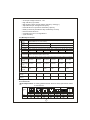
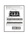
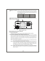
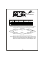
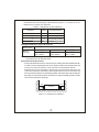
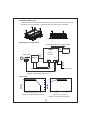
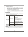
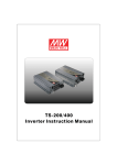
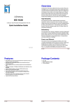
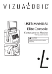
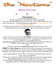
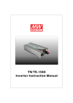
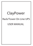
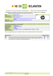
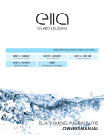
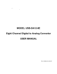
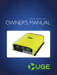
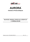
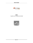
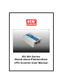
ISI-501 Series
Stand-alone Photovoltaic
(PV) Inverter User Manual
Stand-alone Photovoltaic
(PV) Inverter User Manual
Table of Contents
1.Safety Guidelines ................................................................................... 1
2.Introduction ............................................................................................ 1
2.1 Features........................................................................................... 1
2.2 Main Specification ............................................................................ 2
3.User Interface Panel ............................................................................... 2
3.1 Front Panel ...................................................................................... 2
3.2 LED indicator on Front Panel ............................................................ 3
3.3 Rear Panel ....................................................................................... 3
4.Output Voltage and Frequency Settings .................................................. 4
4.1 Initial Factory State .......................................................................... 4
4.2 Procedure to Setting Output Voltage and Frequency ......................... 4
5.Operating ............................................................................................... 6
6.Protection .............................................................................................. 7
6.1 Input Protection ............................................................................... 7
6.2 Output Protection ............................................................................. 7
7.Installation & Wiring ................................................................................ 7
8.Troubleshooting ...................................................................................... 10
9.Warranty ................................................................................................ 10
Nov. 2013 Version 0
1.Safety Guidelines (Please read through this manual before assembling the Inverter)
‧Risk of elect rical sho ck and e nerg y hazard. All failures sho uld be examined by a
qualified tec hnician. Ple ase do n ot remove the case of the inv erte r by you rself!
‧Plea se d o no t install the inverter in places with hig h moisture o r nea r wa ter.
‧Please do no t install the inverter in places with high am bie nt tempe rature, u nde r
direct sunlight, or near fire source.
‧Ple a se o nly co n ne c t ba t ter i es w ith t he s am e b ra nd a nd mo d el n um b er i n o n e
battery bank. Using batteries from different manufacturers or different capacities
is st rictl y prohib ited!
‧Never allow a spark or fla me in the vic inity of the batteries.
‧Make sure the airflow from the fan is not obstructed at both sides (front and back)
of the inverter. (Please allow at least 15cm of space)
‧Please do not stack any objects on the inverter as it may im pede heat dissipation.
‧Please t urn o ff th e inverter throug h th e po wer ON /OFF sw itch , before rem ovin g
the battery.
WARNING: Batteries will have aging problems after years of operation.
It is suggeste d to exe cute re g ul ar battery maintena nce
(e.g. every year). Once aged, the batteries should be changed
by a p rofessional technician, or the failed batteries may
cause fire or other hazards.
Inverter
Inverter
Don't
disasse mble
Keep away from
moistu re
Inverter
Keep away from
fire or high
temperatur e
Don't stack on
the inverter
Inve rter
K eep good
ve ntilation
2.Introduction
‧ISI-5 01 is a t rue sine wav e DC/AC inv erte r eq uip ped with a so lar char ger (with
MPPT) which is digitally controlled by an advanced microprocessor and is designed
for high frequency operation. This high performance inverter can be paired with both
battery and PV modules / panels.
‧ISI-501 can provide 500W pure sine wave output continuously, 550W for 1 minute,
and sustain a peak lo ad of 1000W as long as 30 AC pow er c ycle s.
‧ISI-501 adopts a high frequency design which greatly reduces product weight and
improves ma ximum e fficiency to 88%.
‧ISI-501 has a built-in solar charger with the MPPT function which effectively utilizes
energy from the PV modu le.
‧IS I-5 01 p rog ress es t he c onc ept o f a m iniatur e ind epe nde nt p owe r sta tion . It is
ideal for areas suitab le fo r PV module s an d where mains power is abse nt.
2.1 Features
‧500W rated output
‧Surg e power capability up to 1000W
‧True sine wave (THD<3%)
1
‧AC o utput voltage tole rance : ±3%
‧H igh effic iency up to 88%
‧Built in M PPT solar ch arger, M PPT efficiency: 98% (Typ.)
‧Adjustable ou tput voltage and freq uency
‧LED indication fo r ope ration and battery capacity
‧Battery low a larm (with ele ctrically iso lated dry contact)
‧R em ote O n/Off function
‧C om pliance to FCC / CE regulations
‧3 year warranty
2.2 Ma in Specification
O
U
T
P
U
T
I
N
P
U
T
MODEL
Po wer
Ra ting
Factory
Setting
Output Voltage
112
12 4
148
212
224
248
500W continuous; 550 W for 1 m in.; 100 0W for 3 0 AC power cycle s (450W ;
495W ; 900W f or 112, 2 12 mode ls)
Protection
Bat. Voltage
AC sh ort, over load, an d over te mperatu re
10.5 ~ 15.0V 21.0 ~ 30.0V 42.0 ~ 60.0V 1 0.5 ~ 15.0V 21.0 ~ 30.0V 42.0 ~ 60.0V
DC Current
50A
30 A
15A
5 0A
30A
15A
Efficiency
85%
87 %
87%
8 6%
88%
88%
110Va c, 60Hz (Default )
230Vac, 50Hz (D efault)
100 / 110 / 115 / 120Va c (Adjus table)
200 / 220 / 230 / 2 40Vac ( Adjustab le)
Off Mode
Current Draw Under 1.0mA w hile pow er switch OFF
PROTECTION Ove r current, battery reve rse polarity (internal fuse ), battery low alarm, battery low shutdown
P Open Circu it
35~50 V
V Voltage
M
o
d
u
l
e
45~90V
90~160V
35~ 50V
35~90V
70~1 60V
M PPT Voltage
Range
25~50 V
35~90V
70~160V
25~ 50V
35~90V
70~1 60V
Ma ximum
Sho rt Circu it
Current
11A
7A
4.5A
11A
7A
4.5A
Charg e
Voltag e
14.4V
28. 8V
57.6V
14.4V
28 .8V
57.6V
Charg e
Curre nt
30A
17A
8.5A
30A
17 V
8.5A
AC Charger
3.Main S pec ification
3.1 Front Panel
A AC Output Outlet: To satisfy global demands, there are many optional AC outlets
to choose from.
Receptacle
type
Country
TYPE-A
Standard
USA
TYPE-B
Standard
EUROPE
TYPE-C
Optional
AUSTR ALIA
Certificate
TYPE-D
Optional
U.K
TYPE-E
Optional
JAPAN
TYPE-F
Optional
GFCI
TYPE-U
Optional
UNIVERSAL
Non
2
B LED Indicator (Status): Displays the operation status of the ISI-501.
C LED Indicator (Battery): Displays remaining capacity of battery.
D Function Setting: Output voltage and frequency can be set through this button.
E P ow er O N/O FF S witch : Th e inve rt er will tu rn OFF if the s witc h is in the OFF
position.
F Ventila tion Slits: T he inverter requires good ve ntilation for proper o peration
and for prolonging its lifetime.
E
A
A C OUT PUT
ON
Stat us
O FF
B
Battery
F
C
Setting
D
Figure 3.1 F ront Panel(Type A)
3.2 LED Indicator On Fron t Pa nel
Operation Status Indicator (Status LED) : Represents the current ISI-501 state.
G reen
R ed
Orange
LED Display
Status
N ormal Operation
Remote Off
Error
*Note : When an error occurs, please refer to chapter 8 "Troubleshooting" of the
use r manua l.
Battery Ca pacity Indica tor (Battery LED):R epresents the re maining capacity
of e xte rnal batterie s.
LED Display
Battery Capacity
Orange
40 ~ 70%
G reen
>70%
R ed
<40%
3.3 Rear Pane
A Battery Input(+ ),(-): Pay extra caution to battery polarity whe n wiring.
B Fan Ve ntil atio n Op eni n g: The inv erte r req u ire s go od v e nt ilatio n fo r pr o pe r
ope ration and for prolonging its lifetime.
C Remote ON/OFF Control: While set at ON, the ISI-501 can be powered ON/OFF
through remote control.
Connector Status
Inverter Status
Open
Rem ote ON
Short
Rem ote OFF
3
D Battery Low Alarm: This is an electrically isolated dry contact which can provide
the user with an external control signal. User will be alarmed
of a low battery when the two pins are open while the ISI-501
makes a "Beep" sound.
Ba ttery Status
Conne ctor Status
Alarm
Ba ttery Low
Conne ctor Open
"Beep" Sound
Ba ttery Normal Conne ctor Short
-----
E PV Input Terminal(+),(-): Pay extra caution to PV module polarity whe n wiring.
F Grounding Terminal(FG).
C
D
Rem ot e
ON/ OFF
Bat t er y
l ow al arm
B
BAT TERY I NPUT
A
SOLAR IN PUT
F
Reverse Polarity
Will Damage T he Unit.
E
Figure 3.2 Rear Panel
4.Output Voltage and Frequency Settings
4.1 Initial Factory State
Initially the ISI-501 is set to output 110Vac at 60Hz or 230Vac at 50Hz.
4.2 Procedure to Setting Output Voltage and Frequency
The user can adjust the output voltage and frequency through the function setting
bu tton on the front p an el. A fter chan gin g th e se tting s, th e in verter w ill re boo t
an d se t th e us e r in p ut v alu e s a s d e fau l t. I n the fut u re, e ve n if t h e b att e ry i s
re m ove d, o r is the r e is no s o urc e o f pow er, the inve rter will kee p th ese m os t
rec ent v alu es t hat t he u ser inpu t.
Step 1: The inverter sho uld be turned off while resetting. Input batteries should
be connected and the loads should be remov ed.
Step 2: Use an insulated stick to pre ss do wn on th e se tting bu tton and then turn
on the power sw itch; the Panel's orange colored LED shou ld flash. After
pressing for 5 seconds, the inverter will send out a "Beep" sound. User
can release the button a nd g o on with the setting procedure.
Step 3: Check output voltage and frequency with table 4-1. If the output is desired,
please continue to s tep 5; if not, please continue adjusting according to
step 4 u ntil it is.
4
AC OUTPUT
ON
Status
OFF
Ba tter y
Use an i nsu la ted pl ast ic
st ick to press on t he "Set ti ng"
bu tton
Se tting
Figure 4.1 Adjustin g output voltage and frequen cy
Table 4-1 Voltage & Frequency Chart
O/P Voltage
F reque ncy
100 Vac
(200 Vac)
110Vac
(2 20Vac)
115Va c
( 230Va c)
120 Vac
(240 Vac)
Status
50Hz Battery
Status
60Hz
Battery
●
●
★
●
●
★
★
★
●
●
★
●
●
★
★
★
● Lig ht
Red
Green
Red
Green
Red
Gree n
Red
Gree n
Red
Yell ow
Red
Yell ow
Re d
Yellow
Re d
Yellow
★ Fla shing
S te p 4: P re ss t he se ttin g bu tton aro und 1 secon d befor e let ting go. T he LED
indicators (Table 4-1) will cha nge sta tus. Please adjus t accordingly.
110 Vac
(220Vac) 5 0Hz
115Vac
(2 30Vac) 50Hz
120Vac
(240Vac) 5 0Hz
100Vac
(200Vac) 5 0Hz
1 00Vac
(200Vac) 60Hz
120 Vac
(240Vac) 6 0Hz
115Vac
(2 30Vac) 60Hz
110Vac
(220Vac) 6 0Hz
Figure 4 .2 O utput vo ltage & frequency changing sequence
Ste p 5: When th e outpu t is a t us er's d es ired value, p ress a nd hold th e se tting
button for 3~5 seconds until the inverter makes a "Beep" sound. The output
setting is now complete; the inverter will now save the settings and restart.
5
5.Operation
System On Battery Low Shutdown
Auto Recovery
(SW-ON) Protection
t
AC Output
14.4/28.8/57.6V
Battery
Voltage
13/26/52V
10.5/21/42V
t
ON
Charger
Status
OFF
t1
ON
OFF
OFF
t2
t3
t4
t5
t6
t
t7
Figure 5 .1 O peration Sequence
t1 : Wh en us er turns on the I SI-501 , ba ttery vo ltag e wi ll be sens ed. If battery
voltage is greater than 13/26/52V, it is adequately charged and the charger
circuit will not activate to prevent overcharging.
t2: While the ISI-501 ope rates, battery voltage will slow ly drop; w hen battery
voltage is lower than 13/26/52V, battery low signal is sensed and the charger
will automatically activate and charge accordingly.
t3: If the power provided by the PV module is greater than load consumption, the
battery will increase in voltage. When this battery voltage reaches 14.4/28.8/
57.6, the charger circuit will shut off its charging current to the battery modules,
to prevent the batteries from overcharging.
t4: When battery voltage drops to 13 / 26 / 52V again,the charger will automatically
restart charging action.
t5: If the power provided by the PV module is less than load consumption, even
if the charger is operational, the battery voltage will still drop. When battery
voltage is below 10.5/21/42V, the ISI-501 will shut down output vo ltage to
prevent the battery from over discharging thereby increasing its lifetime.
t6: Under circumstances that the charger continuously charges the battery, the
battery voltage will slowly increase. When battery voltage reaches 13/26/52V,
th e s ystem will re sta rt after three minu te s and s tart prov idi ng AC volta ge
output.
t7: Same action as t3.
The status of the inverter changes depending on the power provided by the
PV module and its load consumption.
6
6.Protection
6.1 Input Protection
(A)PV Module Reverse Polarity Protection: In the case where the user accidently
reverses the polarity of th e PV mo dule, the ISI-501 interna l fus e will blow to
protect o ther circuitr y. Please contact your neare st distribute r or send the
goods back to Mean Well for repair.
(B)Battery Reverse Polarity Protection: In the case where the user accidently
reverses the pola rity of th e battery connection, the ISI-501 internal fuse will
blow to protect other circuitry. Please contact your nearest distributer or send
the goods back to Mean Well for repai r.
(C)Battery Low Shutdown Protection: When the battery voltage is lower than
rated shutdown point, the ISI-501 will shut down to guarantee the lifetim e of
the battery.
(D)Battery Overvo ltag e Protection: W hen the battery volta ge is too high, the
inverter will shut down and an alarm will sound. Please resolve the error and
restart the inverter to return to normal operation.
WARNING:
Before installation or after use, make sure the power ON/OFF switch at
the front panel is in the OFF position to safely wir e or remove battery.
Under normal working conditions, please choose suitable batteries that
are within the input DC voltage range of the inverter (refer to spec ).
If the input DC voltage is too low (e.g. using 12Vdc battery bank for 24Vdc
models), the inverter cannot startup properly.
If the input DC voltage is too high (e.g. using 48Vdc battery bank for 24Vdc
models), the inverter will g et damaged .
6.2 Output Protection
If the ISI-501 detects any of the following errors while operating, the status LED
indicators will stay lit until the error is removed.
(A)Over Temperature Protection(OTP) : When the internal temperature of th e
ISI-501 reaches a threshold, over temperature protection will activate causing
shut down. Wait at least 30 minutes before restarting to recover normal operation.
(B) AC Output Short Circuit Protection: When the AC output of the ISI-501 is
short circuited, it will go into protection. Restart to recover normal operation.
(C) Over Load Protection: When the load is in the over load range of 500~550W
(450~495W for 112/212 mode ls), the inverter can continue supplyi ng power
for a short duration of 1 minute. If the load is no t removed, the sensing circuit
will activate causing shut down.
7. Installation & Wiring
(A)Wiring for batteries: Wire connection should be made as short as possible less
tha n 1. 5m is highly reco mmended. Also m ake sure s uita ble wires are chosen
based on safety requirement and current rating. Cross sections that are too small
will result in lower efficiency, less output power, and the wires may also become
7
o ve rh eat ed a nd c au s e d a nge r. P lea se re fe r to ta bl e 7 .1 o r co nsu lt u s or o ur
distributors if yo u have any questions.
Table 7-1 Sug gestion for w ire selection
Cross section of wire
2
lead(mm )
AWG
Suggested Model
1.5
14
PV module input wire
2.5
12
48V b attery m odels
4
10
24V b attery m odels
6
8
12V b attery m odels
(B)Suggested Ba ttery Type and Capacity
Battery Typ e
Battery
Capacity
Lead-acid
12V models
24V models
48V m odels
12V / 120Ah ~
24V / 60Ah ~
48V / 30Ah ~
12V / 400Ah
24V / 200A h
48V / 100A h
Note : If the desired battery type is not Lead-Acid based, please contact the battery
manufacturer for an advised value.
(C)Installation Requirements:
‧The unit should be mounted on a flat surface or holding rack with suitable strength.
In order to ensure the lifespan of the unit, please refrain from operating the unit
in dusty or mo ist e nvironments. This is a power unit with built-in DC fan.
P lease m ake sure the ve ntilation opening s are no t blo cke d an d refrain from
c ontinuous opera tion with heavy l oad in high am bient environment becaus e
this may prevent inverter from operating properly and its life span may be affected.
We highly recommend tha t there should be no objects impeding airflow within
15cm of the ventilation openings.
>15cm
Air
>15cm
Inverter
Air
Figu re 7.1: E xam ple of In stallation
8
(D)Suggested Mounting
The case has four reserved holes for fixing, the user can utilize these to mount
the ISI-501 as shown below. It is advi sed to mount the ISI-501 horizontal.
(E)Example of System Setup
Leads should be as short as possible
Large r
than
15cm
AC O/P
Solar panel
ISI-501
Inverter
Larger
than
15cm
Battery
DC I/P
+
AC Load
- +
-
S olar
I/P FG
+ -
Wall or system FG
Leads should be less than 1.5m
Based on th e actual length o f wiring, choose
suitabl e cross-sect ion of the leads
(F)Deratin g
100
100
80
80
60
60
50
40
40
20
20
-20
0
10
20
30
40
50
60
10.5VDC
21VDC
42VDC
Ambi ent Temperature (℃) Ta
11.5VDC
23VDC
46VDC
15VDC
30VDC
60VDC
(HORIZONTAL)
Bat tery In put Vo ltage (V)
Figure 7.2 Output Derating Curve
Figure 7.3 Input Derating Curve
9
(G)
Notes on O utput Loads:
ISI-501 Series can power most equipment requiring an AC source of 500W,
but for certain type of load, the unit may not work properly.
(1 )Sin c e indu ctive loa d s o r mo tor based e quip ments n eed s a la rge s ta rt up
current (6~10 times of its rated current), please make sure this startup current
is less than the maximum current capability o f the inverter.
(2 )Wh en the loads are cap acitive o r rectified equip ments (such as switching
power supply), we suggest operating these equipment at no load or light load
during power ON. Increase the load slowly only after the IS I-501 has started
up to ensure proper operation.
8. Troubleshooting
ISI-50 1 is a complex product which should b e serviced by pro fessional technician.
Improper usage or modification may damage the unit or result in shock hazard. If you
are not able to clear the failure condition according to the following instructions, please
contact us or your closest d istributo r for repair se rvice.
Failure S tatu e
Possible Reason s
Recommended Solutions
Abnormal Input
Check the DC input sources (PV/ battery)
to make sure the voltage is within the
required range
M a k e s u re t ha t t he v e n ti la t io n i s n o t
Over Temperature
Protection
N o A C Ou tpu t
Voltage
Ma k e su re t he o utp ut lo ad do e s n o t
Overload Protection
Battery
D isch arging
Period to short
blocked and the ambient temperature
is not too high. Please derate load usage
or lower the ambient temperature
ex cee d th e ra t ed val u e or t he peak
startup current is not too high, typically
found in inductive or capacitive loads
Short Circuit Protection
Make sure the output is not overloaded
or short circuited
Battery Aged or Broken
Replace the batteries
Battery Capacity is
too Sma ll
Reconfirm battery specification and
enlarge the battery capacity as suggested
9. Warranty
Three years of warranty is provided under normal operating conditions. Please
do not change components or modify the unit by yourself or attempt to repair
the unit by yourself because Mean Well reserves the right to void the w arranty.
10