1
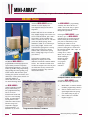
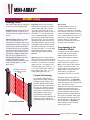
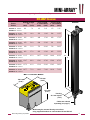
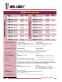
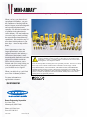
™
MINI-ARRAY
Measuring Light Screen System
™
MINI-ARRAY
Measuring Light Screen System
MINI-ARRAY Features
Advanced MINI-ARRAY software†
includes on-screen displays for
error/diagnostic analysis and sensor
alignment.
Emitters and receivers are available in
array lengths ranging from 6 inches to 4
feet in 6 inch increments, plus 5 and 6
foot models. All are available with
either .375-inch (9.53 mm) or .750-inch
(19.05 mm) beam spacing, which
translates to either 32 or 16 beams per
foot of array length. Sensors with
3/8-inch beam spacing have a sensing
range of up to 20 feet (6.1 meters).
Sensors with 3/4-inch beam spacing
have a sensing range of up to 55 feet
(16.8 meters).
The Banner MINI-ARRAY is a
programmable measuring light screen
system ideally suited for inspection
and profiling applications. It excels at
on the fly product sizing and profiling,
edge-guiding and center-guiding, loop
tension control, hole detection, parts
counting, die ejection verification, and
similar uses. Each system consists of a
controller module, an
emitter and receiver, and
two interconnecting cables.
The MINI-ARRAY ’s
compact controller module
may be either factory or
user programmed for any
one or two of ten
measurement modes and
any one of four scanning
modes. Programming is
accomplished via the
controller’s built-in serial
interface using a PCcompatible computer
running Windows® 3.1,
Windows® 95, or OS/2®.
2
†
System status, including sensor
alignment, is displayed via LED
indicators on both the controller and the
sensors. The controller module offers
two discrete outputs (one reed relay and
one solid-state dc relay) which can be
separately assigned to any of the ten
measurement modes.
The MINI-ARRAY ’s programming
versatility also allows the user to
“blank” areas of the array to ignore
objects that must pass undetected
through the light curtain.
Utilizing the MINI-ARRAY ’s serial
interface, up to 15 MINI-ARRAY
controllers may be assigned separate
IDs and either placed on an RS485
party line or controlled by a host.
Scanning can either be set for
continuous operation or triggered by a
presence-sensing device connected to
the optically-isolated “Gate” input. In
lieu of a presence
sensing device, “Host
Mode” may be used, in
which scanning is
initiated by either
a host computer
or a programmable logic
controller.
Compact Emitters and Receivers
A complete MINI-ARRAY system
includes the following components:
1
Model MAC-1 controller module
(includes programming software)
1 ea.
Sensors: emitter and receiver of
equal length and beam spacing
(see model listing on page 6)
2
Sensor cables (see available
lengths on page 7)
Programmable Windows® Software
Banner Engineering Corporation
™
MINI-ARRAY
Measuring Light Screen System
MINI-ARRAY Programming Features
Measurement Modes
The MAC-1 controller is a highlyversatile microcontroller-based module.
It is configured using the supplied
Banner software via its built-in RS-232
interface, using a PC-compatible
computer running Windows® 3.1 or 95
or OS/2®. The Banner MINI-ARRAY
System may be programmed for any
one or two of the following
Scan Analysis Modes:
First Beam Blocked (FBB):
The controller identifies the location of
the first blocked beam. Beams are
numbered, beginning at the cabled end
of the sensor, and continuing in
sequence to the opposite end of the sensor.
Last Beam Blocked (LBB):
The controller identifies the location of
the last blocked beam.
Total Beams Blocked (TBB):
The controller totals the number of
blocked beams.
Contiguous Beams Blocked (CBB):
The controller totals the number of
contiguous beams blocked in each
group of blocked beams along the
length of the sensor.
First Beam Made (FBM):
The controller identifies the location of
the first unblocked beam.
Last Beam Made (LBM):
The controller identifies the location of
the last unblocked beam.
Total Beams Made (TBM):
The controller totals the number of
unblocked beams.
Contiguous Beams Made (CBM):
The controller totals the number of
contiguous unblocked beams in each
group of unblocked beams along the
length of the sensor.
All Data (ALL):
The controller passes all beam condition
data for every scan to the serial interface
for analysis by a host computer or
controller.
Vehicle Separation (VHS):
Controller output #1 is energized
whenever six or more inches of curtain
length are blocked (i. e. - contiguous
beams blocked), and de-energizes when
all beams become unblocked.
Output Programming
The controller offers two outputs.
Output #1 is a reed relay contact rated
at 125V ac or dc maximum (10VA
maximum resistive load).
Output #2 is a current sinking solidstate switch rated at 30V dc max., 150
mA max. One scan analysis mode may
be assigned to Output #1 and a second
(different) analysis mode to Output #2.
For each scan analysis mode, the
following output response criteria may
be programmed:
Set Point (Low and High) determines
where within the array the output(s) will
respond. In the case of total or
contiguous beams made or blocked,
these settings determine the minimum
and maximum number of beams
required to produce an output.
Hysteresis (Low and High) determines
how much change must occur at each
set point to cause the associated output
to change state. Hysteresis avoids
unstable output conditions (e. g. “chattering” of the output) when the
scanning condition exactly matches one
of the set points.
Scan # is the number of consecutive
scans of the array that are required
before the associated output is updated.
The controller may be programmed for
from 1 to 9 consecutive scans. The scan
data must be identical for all
consecutive scans in order for the
outputs to be updated.
Invert (Y/N) allows the output to be
either normally open (“No”) or
normally closed (“Yes”).
Output #2, labeled Alarm on the
controller module, can be
programmed to function as the
alarm output for the module’s
self-diagnostic circuitry
whenever it is not assigned to a
scan analysis mode. Alternatively,
Output #2 may be programmed to
serve as a trigger input to initiate
the scan sequence of another
MINI-ARRAY System.
Banner Engineering Corporation
3
™
MINI-ARRAY
Measuring Light Screen System
MINI-ARRAY Scanning
Scanning Modes
The control module may be configured
for any one of four scanning modes:
Straight Scan is the default mode. All
beams are scanned in sequence from
the cable end to the opposite end of the
sensors.
Interlaced Scan alternates a straight
scan with a slanted-beam scan. A
slanted-beam scan begins with a beam
established between the #2 emitter and
the #1 receiver, and next between the
#3 emitter and #2 receiver, continuing
to between the last emitter and next to
last receiver. The last emitter is then
reactivated to establish a beam to the
last receiver to complete the scan.
Alternating slanted-beam scans with
straight scans improves optical
resolution within the middle one-third
of the scanning distance. See the
figure, below.
Resolution is increased
in the middle 1/3 of the
range
Edge Scan activates only the beams
located near the top edge of an object
which is in the light screen. (NOTE:
“top edge” refers to the edge of the
object passing nearest to the top end of
the sensors, i. e. - the top of the light
screen.) Each scan begins six beams
prior to the last beam blocked during
the previous scan. The scan continues
upward from this point and ends at the
first unblocked beam. Edge Scan mode
is designed to reduce sensing response
time when measuring or locating only
one edge of an object. Use of the Edge
Scan mode limits the scan analysis
mode selection to LBB (Last Beam
Blocked).
Skip Scan quickens sensing response
time at the expense of decreased sensing
resolution. The Skip Scan mode allows
from one to seven beams to be skipped
during each scan. For example, with
one beam skipped, only beams #1, 3, 5,
7, etc. will be interrogated. With two
beams skipped, only #1, 4, 7, 10, etc.
will be interrogated, and so on.
Control of Scanning
Interlaced Scan Mode
4
The controller module may be
programmed for either continuous
scanning or gated scanning. The
module’s optically-isolated GATE
input is energized by application of
10 to 30V dc. Gating is typically
accomplished using a dc presence
sensing device. Alternatively, the
MINI-ARRAY System may be
programmed for “Host Mode”
control, which allows scanning to be
initiated by a host computer or a
programmable logic controller (PLC).
Host Control
The MINI-ARRAY System can
communicate with either a host
computer or a controller via either RS232 or RS-485 serial protocol. The host
can direct the MINI-ARRAY System to
scan on demand and/or receive the scan
data directly from the MINI-ARRAY
System in binary or ASCII form.
Selectable communication baud rates
are 9600, 19200, and 38400.
Programming of the
Controller Module
Configuration of the MINI-ARRAY
control module is done using the
Banner-supplied software and an
ordinary PC-compatible computer.
Programmed system configurations,
called “Parameter Setup Files” (or
PSFs), can be stored in the controller
module’s non-volatile memory. The
supplied software can create and store
multiple PSFs in computer files for
instant call-up of a particular
configuration whenever it is needed.
The Banner software also offers two
other useful features. An Alignment
screen displays the individual status of
each beam along the entire length of the
array. The same screen also
summarizes the total beams blocked and
unblocked and indicates the beam
numbers of the first beam blocked, the
first beam unblocked, the last beam
blocked, and the last beam unblocked.
This screen is invaluable during setup
for monitoring and analyzing exactly
what is being seen by the light screen.
The second feature, a Diagnostics
screen, indicates problems with the
emitter or the receiver.
Banner Engineering Corporation
™
MINI-ARRAY
Measuring Light Screen System
MINI-ARRAY Dimensions
Housing Length
L1
(mm)
(inch)
Sensor
Models
Array Length
Y (16 beams/ft)
(mm)
(inch)
Array Length
Y (32 beams/ft)
(mm)
(inch)
BMEL6..A emitter
BMRL6..A receiver
201
7.9
143
5.62
133
5.25
BMEL12..A emitter
BMRL12..A receiver
356
14.0
295
11.62
286
11.25
BMEL18..A emitter
BMRL18..A receiver
505
19.9
448
17.62
438
17.25
BMEL24..A emitter
BMRL24..A receiver
659
26.0
600
23.62
591
23.25
BMEL30..A emitter
BMRL30..A receiver
810
31.9
752
29.62
743
29.25
BMEL36..A emitter
BMRL36..A receiver
963
37.9
905
35.62
895
35.25
BMEL42..A emitter 1115
BMRL42..A receiver
43.9
1057
41.62
1048
41.25
BMEL48..A emitter 1267
BMRL48..A receiver
49.9
1210
47.62
1200
47.25
BMEL60..A emitter 1572
BMRL60..A receiver
61.9
1514
59.62
1505
59.25
BMEL72..A emitter 1877
BMRL72..A receiver
73.9
1819
71.62
1810
71.25
Sensors
L1
Y
MAC-1 Controller Module
75.0 mm
(2.95")
1
M
C INIO A
N R
TR R
O AY
LL
ER
R
S-
M
23
2
AC
1
100.0 mm
(3.94")
2
s
W
ire
9
8
EM
TR
7
6
5
R
C
VR
4
3
5
BU
BR
PO
2 WE
R
1
+12V
11
15
14
13
AL
IG
12
N
G
AT
E
10
D
O
U
T
AR 1
M
L
16 2
-3 L
1.2 0V 1
m AC
A
3
M
CO
DR
IA
G
D
3
IA
G
D
2
IA
G
1
15
14
T/R
AL
F1
4
13
3
15 0V
12
0m
11
AL Ma A AR x RS +
10
48
M
5
9
10
-3
8
G 0V +
AT D
E C 50
7
0m
M
O ax A
6
U
W
T
1
5
H
BK
N
T/R
110.0 mm
(4.33")
Housing
38.1 mm square
(1.50")
Cables are ordered
separately (see page 7)
Module may be mounted directly to a surface
using supplied hardware or onto standard 35 mm DIN rail.
Banner Engineering Corporation
5
™
MINI-ARRAY
Measuring Light Screen System
MINI-ARRAY Sensor Specifications
Emitter
Receiver
Emitter
Receiver
Emitter
Receiver
Emitter
Receiver
Emitter
Receiver
Emitter
Receiver
Emitter
Receiver
Emitter
Receiver
Emitter
Receiver
Emitter
Receiver
Array
Length
143 mm
(5.62 in)
295 mm
(11.62 in)
448 mm
(17.62 in)
600 mm
(23.62 in)
752 mm
(29.62 in)
905 mm
(35.62 in)
1057 mm
(41.62 in)
1210 mm
(47.62 in)
1514 mm
(59.62 in)
1819 mm
(71.62 in)
Total
Beams
8
16
24
32
40
48
56
64
80
MINI-ARRAY Sensors - 32 beams/foot
models with 0.38" (9.7 mm) beam spacing
MINI-ARRAY Sensors - 16 beams/foot
models with 0.75" (19.1 mm) beam spacing
Models
BMEL616A
BMRL616A
BMEL1216A
BMRL1216A
BMEL1816A
BMRL1816A
BMEL2416A
BMRL2416A
BMEL3016A
BMRL3016A
BMEL3616A
BMRL3616A
BMEL4216A
BMRL4216A
BMEL4816A
BMRL4816A
BMEL6016A
BMRL6016A
BMEL7216A
BMRL7216A
96
Models
BMEL632A
BMRL632A
BMEL1232A
BMRL1232A
BMEL1832A
BMRL1832A
BMEL2432A
BMRL2432A
BMEL3032A
BMRL3032A
BMEL3632A
BMRL3632A
BMEL4232A
BMRL4232A
BMEL4832A
BMRL4832A
BMEL6032A
BMRL6032A
BMEL7232A
BMRL7232A
Emitter
Receiver
Emitter
Receiver
Emitter
Receiver
Emitter
Receiver
Emitter
Receiver
Emitter
Receiver
Emitter
Receiver
Emitter
Receiver
Emitter
Receiver
Emitter
Receiver
Array
Length
133 mm
(5.25 in)
286 mm
(11.25 in)
438 mm
(17.25 in)
591 mm
(23.25 in)
743 mm
(29.25 in)
895 mm
(35.25 in)
1048 mm
(41.25 in)
1200 mm
(47.25 in)
1505 mm
(59.25 in)
1810 mm
(71.25 in)
Emitter/receiver range:
3/8” Beam Spacing
3/4” Beam Spacing
0.6 to 6.1 m (2 to 20 ft) for sensors < 4 feet
0.9 to 17 m (3 to 55 ft) for sensors < 4 feet
0.6 to 4.6 m (2 to 15 ft) for sensors > 4 feet
0.9 to 14 m (3 to 45 ft)for sensors > 4 feet
Note: Maximum range is specified at the point where 3x excess gain remains
Minimum object sensitivity:
3/8” Beam Spacing
3/4” Beam Spacing
19.1 mm (.75 in)
38.1 mm (1.5 in)
Interlaced Mode: 12.7 mm (.5 in)*
Interlaced Mode: 25.4 mm (1.0 in)*
*Note: Assumes sensing is in middle one-third of scanning range (see page 4)
Sensor Scan time
55 microseconds per beam, plus 1 millisecond processing time per scan.
Power Requirements:
12V dc ±2% supplied by
controller
Emitter
0.10 amps max. @ 12V dc
Total
Beams
16
32
48
64
80
96
112
128
160
192
Receiver
3/8-inch beam spacing - 0.75 amps max. @ 12V dc
3/4-inch beam spacing - 0.50 amps max. @ 12V dc
Note: Maximum current is for a 6-foot sensor
Connections:
Sensors connect to controller using two 5-conductor quick disconnect cables (one for emitter and one for receiver),
ordered separately. Use only Banner cables, which incorporate a “twisted pair” for noise immunity on RS485 data
communication lines. Cables measure .32-inch (8.1 mm) in diameter, and are shielded and PVC-jacketed. Conductors
are 20-gauge. Emitter and receiver cables may not exceed 250 feet, each. See bottom of page 7.
Status indicators:
Emitter
Red LED lights for proper operation
Enclosures:
Emitter and receiver:
Size: see Figure, page 5
Material: Aluminum, with black anodized finish; acrylic lens cover
Rating: NEMA 4, 13 (IP 65)
Operating Temperature:
-20 to 70º C (-4 to 158º F); 95% max. rel. humidity (non-condensing)
6
Receiver
Green = sensors aligned (> 3x excess gain)
Yellow = marginal alignment (1x < excess gain < 3x)
Red = sensors misaligned or beam(s) blocked
Banner Engineering Corporation
™
MINI-ARRAY
Measuring Light Screen System
MINI-ARRAY Controller Specifications
Power requirements:
16 to 30V dc @ 1.25 amps max. (see current requirements for sensors); controller, alone,
(without sensors connected) requires 0.1 amp.
Inputs:
MINI-ARRAY sensor input (5 connections); emitter and receiver wire in parallel to five
terminals. GATE input is optically-isolated, requires 10 to 30V dc (7.5K input impedance) for
gate signal.
Response Time:
Outputs are inactive for 5 seconds after system power up. Maximum response time for the
discrete outputs are two scan cycles. A scan cycle includes a sensor scan plus any serial data
transmission. Serial transmission (if activated) follows every sensor scan.
Discrete Outputs:
Output 1 (OUT 1) - Reed relay contact rated 125V ac/dc max., 10 VA max. resistive load (noninductive).
Output 2 (ALARM) - Open collector NPN transistor rated 30V dc max., 150 mA max, shortcircuit protected; may be configured as a second data analysis output, a system alarm output,
or a scan trigger output for a secondary device (e.g. camera, MINI-ARRAY etc.).
OFF-STATE Leakage Current:
ON-STATE Saturation Voltage:
< 10µA @ 30V dc
< 1V @ 10mA
<1.5V @ 150mA
Serial Data Outputs:
RS-232, RS-485, ASCII or binary data format,
Baud rate: 9600, 19.2K, or 38.4K,
8 data bits, 1 start bit, 1 stop bit, even parity,
Clear data may be suppressed,
Header string may be suppressed in binary format,
Up to 15 controllers may be given unique addresses for RS485 party line.
Controller programming:
Via RS232 to PC-compatible computer running Windows® 3.1 or 95 or OS/2® operating system
and using supplied Banner software (see user manual).
Status Indicators:
The following status LEDs are located on the top surface of the module:
OUT 1 (red) - Indicates that Output 1 is energized,
ALARM (red) - Indicates that Output 2 is energized,
GATE (red) - Indicates voltage is applied to GATE input,
ALIGN (green) - Indicates sensors aligned (excess gain > 1x),
DIAG 1 (green) - Indicates power is applied to the module,
DIAG 2 (red) - Indicates receiver failure,
DIAG 3 (red) - Indicates emitter failure.
Enclosure:
Size: see Figure, page 5
Material: Polycarbonate
Rating: NEMA 12 (IP 52)
Operating Temperature:
-20 to +70°C (-4 to 158°F); 95% relative humidity (non-condensing).
Cables (2 required per system)
Model
Length
QDC-515C
4.6 m (15 ft) cable, straight QD connector
QDC-525C
7.6 m (25 ft) cable, straight QD connector
QDC-550C
15.2 m (50 ft) cable, straight QD connector
Banner Engineering Corporation
7
™
MINI-ARRAY
Measuring Light Screen System
When you buy your photoelectric
equipment from Banner, you gain
the confidence of dealing with the
nation's largest, most knowledgeable
and experienced photoelectric
company. We have the broadest line
of products in the photoelectric
sensor industry. We can handle any
size order, large or small, utilizing
the most advanced manufacturing
capabilities. We can deliver any of
more than 10,000 products in just
three days – most can ship within
hours.
Just as important, we have the
largest photoelectric sales and
support network in the industry, a
collection of the industry's most
knowledgeable distributors and sales
engineers, available worldwide.
We're close by wherever you're
located, and we're ready to help you
with your applications, plus give
you excellent service support.
When you add it all up, you'll find
more value in Banner products.
For more information or
applications assistance:
Call 612-544-3164
Banner Engineering Corporation
P.O. Box 9414
Minneapolis, MN 55440
Phone: 612-544-3164
Fax: 612-544-3213
P/N 44925
Printed in USA
!
WARNING! These photoelectric presence sensors do NOT include the selfchecking redundant circuitry necessary to allow their use in personnel safety
applications. A sensor or controller failure or malfunction can result in either
an energized or a de-energized condition.
Never use these products as sensing devices for personnel protection. Their use as a safety
device may create an unsafe condition which could lead to serious injury or death.
Only MINI-SCREEN™, MULTI-SCREEN™, MACHINE-GUARD, and PERIMETERGUARD Systems, and other systems so designated, are designed to meet OSHA and
ANSI machine safety standards for point-of-operation guarding devices. No other Banner
sensors or controls are designed to meet these standards, and they must not be used as
sensing devices for personnel protection.