1
HI-3638
ELF / VLF
Electric Field Meter
User Manual
ETS-Lindgren Inc. reserves the right to make changes to any product described
herein in order to improve function, design, or for any other reason. Nothing
contained herein shall constitute ETS-Lindgren Inc. assuming any liability
whatsoever arising out of the application or use of any product or circuit
described herein. ETS-Lindgren Inc. does not convey any license under its
patent rights or the rights of others.
© Copyright 1994–2013 by ETS-Lindgren Inc. All Rights Reserved. No part
of this document may be copied by any means without written permission
from ETS-Lindgren Inc.
Trademarks used in this document: The ETS-Lindgren logo and Probeview II are
trademarks of ETS-Lindgren Inc.
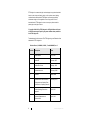
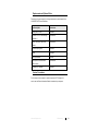
Revision Record | MANUAL,HI-3638 | Part #H-600062, Rev. G
Revision
ii
Description
Date
Initial Release
July, 1994
A
Added CE
October, 1997
B
Added Error Codes
January, 1998
C
Updated area code
February, 2000
D
Rebrand
March, 2009
E
Updated electric field information,
Replacement and Optional Parts,
Specifications, Operating Protocols
February, 2011
F
Added Operating Protocols as
appendix
April, 2011
G
Updated Replacement and
Optional Parts
April, 2013
www.ets-lindgren.com
Table of Contents
Notes, Cautions, and Warnings ................................................ v
1.0 Introduction .......................................................................... 7
ETS-Lindgren Product Information Bulletin ................................................. 8
2.0 Maintenance ......................................................................... 9
Annual Calibration ...................................................................................... 9
Maintenance of Fiber Optics ..................................................................... 10
Replacement and Optional Parts .............................................................. 11
Service Procedures .................................................................................. 11
3.0 Specifications ..................................................................... 13
HI-3638 Typical Frequency Response ...................................................... 15
4.0 HI-3638 Controls and Connectors .................................... 17
Transmit / Receive .................................................................................... 17
ELF/OFF/VLF ........................................................................................... 18
Charge...................................................................................................... 18
Ground ..................................................................................................... 18
Output....................................................................................................... 18
5.0 Battery Charger .................................................................. 19
Setting the Voltage ................................................................................... 19
Charging the Battery ................................................................................. 20
Battery Tips .............................................................................................. 21
Operating Temperature ..................................................................... 21
Charging ........................................................................................... 21
6.0 Application ......................................................................... 23
Meter ........................................................................................................ 23
Sensor Theory .......................................................................................... 23
7.0 Power Frequency Fields.................................................... 25
8.0 Guidelines for EMF Exposure ........................................... 29
Radio Frequency Exposure / Emission Standards Pertinent to VDT
Frequency Range ..................................................................................... 30
Appendix A: Warranty ............................................................. 31
www.ets-lindgren.com
iii
Appendix B: Operating Protocols .......................................... 33
Communication Protocol ........................................................................... 33
Information Transfer Protocol .................................................................... 33
Probe Commands ..................................................................................... 34
Error Codes .............................................................................................. 35
Appendix C: References ......................................................... 37
Appendix D: EC Declaration of Conformity .......................... 41
iv
www.ets-lindgren.com
Notes, Cautions, and Warnings
Note: Denotes helpful information intended to
provide tips for better use of the product.
Caution: Denotes a hazard. Failure to follow
instructions could result in minor personal injury
and/or property damage. Included text gives proper
procedures.
Warning: Denotes a hazard. Failure to follow
instructions could result in SEVERE personal injury
and/or property damage. Included text gives proper
procedures.
See the ETS-Lindgren Product Information Bulletin for safety,
regulatory, and other product marking information.
www.ets-lindgren.com
v
This page intentionally left blank.
vi
www.ets-lindgren.com
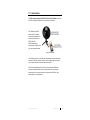
1.0 Introduction
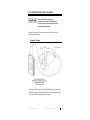
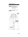
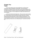
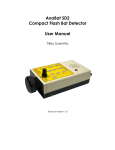
The ETS-Lindgren Holaday HI-3638 ELF/VLF Electric Field Meter provides full
ELF/VLF (extremely low frequency/very low frequency) capability.
The HI-3638 covers MPR
bands I and II for Swedish
low-emission standards, plus
meets test requirements for
IEEE 1140-1994
(IEEE standard for the
measurement of electric fields
from video display terminals).
(Tripod not included)
The HI-3638 is useful in low field intensity measurements such as video display
terminals (VDTs) and computer monitors, as well as higher field environments
such as power transmission lines and industrial locations.
The HI-4416 Digital Readout/Control Unit is included with the HI-3638 and
provides an optically isolated, full control digital readout for quick and easy
measurements in any sensor orientation. An optional HI-4413P Fiber Optic
Modem allows for a serial interface.
www.ets-lindgren.com
Introduction
7
ETS-Lindgren Product Information Bulletin
See the ETS-Lindgren Product Information Bulletin included with your shipment
for the following:
8
Warranty information
Safety, regulatory, and other product marking information
Steps to receive your shipment
Steps to return a component for service
ETS-Lindgren calibration service
ETS-Lindgren contact information
Introduction
www.ets-lindgren.com
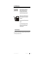
2.0 Maintenance
Before performing any maintenance,
follow the safety information in the
ETS-Lindgren Product Information
Bulletin included with your shipment.
WARRANTY
Maintenance of the HI-3638 is limited to
external components such as cables or
connectors.
Warranty may be void if the enclosure is
opened.
If you have any questions concerning
maintenance, contact ETS-Lindgren
Customer Service.
Annual Calibration
See the Product Information Bulletin included with your shipment for information
on ETS-Lindgren calibration services.
www.ets-lindgren.com
Maintenance
9
Maintenance of Fiber Optics
Fiber optic connectors and cables can be damaged from airborne particles,
humidity and moisture, oils from the human body, and debris from the connectors
they plug into. Always handle connectors and cables with care, using the
following guidelines.
Before performing any maintenance, disconnect
the fiber optic cables from the unit and turn off
power.
When disconnecting fiber optic cables, apply the
included dust caps to the ends to maintain their
integrity.
Before connecting fiber optic cables, clean the
connector tips and in-line connectors.
Before attaching in-line connectors, clean them
with moisture-free compressed air.
Failure to perform these tasks may result in
damage to the fiber optic connectors or cables.
10
Maintenance
www.ets-lindgren.com
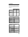
Replacement and Optional Parts
Following are the part numbers for ordering replacement or optional parts for the
HI-3638 ELF/VLF Electric Field Meter.
Part Description
Part Number
Battery Pack, 12 VDC
H-491069
Universal 12 VDC Trickle Charger
(110/240 V)
H-491063-06
Cable, Fiber Optic, Glass, Dual,
2-Meter
H-491106-02
HI-3638 Carrying Case
H-491100
Tripod
H-491009
Fiber Optic Modem
HI-4413P
Fiber Option to USB Converter,
USB interface
HI-4413USB
Probeview II™ Software
H-491255
Service Procedures
For the steps to return a system or system component to ETS-Lindgren for
service, see the Product Information Bulletin included with your shipment.
www.ets-lindgren.com
Maintenance
11
This page intentionally left blank.
12
Maintenance
www.ets-lindgren.com
3.0 Specifications
Instrument accuracy is derived from a field calibration using a 30 cm TEM cell
creating a known electric field. A sinusoidal voltage impressed on the TEM cell is
directly measured using a true RMS detector and used to calculate the electric
field strength in V/m.
Band 1 ELF
Frequency Range:
Filter Attenuation:
Band II VLF
5 Hz–2000 Hz
2 kHz–400 kHz
Bandwidth (-3dB)
Bandwidth (-3dB)
-80 dB/dec
below 5 Hz
-80 dB/dec
below 2 kHz
-40 db/dec
above 2 kHz
-40 dB/dec
above 400 kHz
Bands I and II
Measuring Ranges:
4, 40 V/m, 0.4, 4, 40 kV/m F.S.
Measuring Limit:
1 V/m
Linearity:
±0.5 dB + 1% of Full Scale
Calibration Accuracy:
±0.5 dB @ Calibration Points
Display Resolution:
3 1/2 Digit LCD
0.01 V/m
Waveform Out
Output Sensitivity:
1 Volt/Full Scale Range
Output Impedance:
1Ω
Waveform Out Jack:
Grounding Jack:
www.ets-lindgren.com
3.5 mm (0.14 in) Phone Jack
Standard Banana Jack
Specifications
13
+10°C to +40°C
Operating Temperature:
+50°F to +104°F
Humidity:
5% to 95% Relative Humidity,
Non-condensing
Isotropicity:
Single Axis
Fiber Optic Connectors:
Standard FSMA
Fiber Optic Cable:
200 Micron, Graded Index,
Multimode
Readout:
HI-4416 Digital Readout/Control
Unit
Probe Mount:
1/4–20 UNC tapped hole
(internal thread)
Two, 90 degrees apart
Battery
Battery Type
Current Consumption:
Battery Life:
Battery Charger:
Battery Charger Jack:
12 Volt DC, 1400 mAh
Nickel-Cadmium (NiCd)
35 mA
40 Hours (Nominal)
110/240 VAC, 16 Hour
2.5 mm (0.1 in) Phone Jack
Physical Specifications
Height:
Diameter
Weight:
14
Specifications
102 mm (4 in)
305 mm (12 in)
0.91 kg (2 lb)
www.ets-lindgren.com
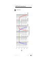
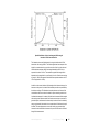
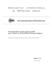
HI-3638 Typical Frequency Response
Measured at 20 V/m.
www.ets-lindgren.com
Specifications
15
This page intentionally left blank.
16
Specifications
www.ets-lindgren.com
4.0 HI-3638 Controls and Connectors
Before connecting or operating any
components, follow the safety information in
the ETS-Lindgren Product Information Bulletin
included with your shipment.
Following is a description of the controls and connectors for the HI-3638
ELF/VLF Electric Field Meter.
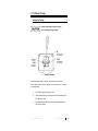
Transmit / Receive
Plug the fiber optic cable from the HI-4416 Digital Readout/Control Unit into the
TRANSMIT connector and RECEIVE connector on the HI-3638, matching white
to white (for transmit) and yellow to yellow (for receive).
www.ets-lindgren.com
HI-3638 Controls and Connectors
17
When the fiber optic cable is not connected, cover the cable and connectors with
the protective plastic caps supplied. This prevents dirt or other contaminants from
entering the connector and causing communication problems. See Maintenance
of Fiber Optics on page 10 for more information.
ELF/OFF/VLF
This switch activates and deactivates the HI-3638 as well as the selection of ELF
or VLF bands. LEDs indicate which band is selected.
In the ELF or VLF position the HI-3638 is powered by the internal 12 VDC
nickel-cadminum (NiCd) battery. To prolong battery life, set the switch to OFF
when not in use.
Charge
A 16-hour trickle battery charger is supplied with the HI-3638. The
battery charger can charge the HI-3638 or the HI-4416.
Slight overcharging up to 24 hours will not harm the battery; however, charging
the battery longer than 24 hours may degrade battery performance.
Ground
Connect GND to earth ground to establish a reference for the HI-3638.
Output
Connect an oscilloscope to OUTPUT to observe the waveform of the signal
driving the true RMS to DC converter circuit.
18
HI-3638 Controls and Connectors
www.ets-lindgren.com
5.0 Battery Charger
Setting the Voltage
Disconnect the battery charger from power
before changing the voltage setting.
Check the viewing window on the power entry module to verify that the
battery charger is set to the proper voltage for your AC power source. To change
the voltage setting:
1.
Disconnect the battery charger from power.
2.
Use a small screwdriver to loosen and remove the fuse assembly from
the power entry module.
3.
Slide the small board located on the back of the fuse assembly from
right to left to remove it.
www.ets-lindgren.com
Battery Charger
19
4.
Rotate the board so the desired voltage is facing up, and then reinsert
it into the fuse assembly. The desired voltage should be visible in the
viewing window.
5.
Firmly re-seat the fuse assembly back into the power entry module.
The battery charger is ready to use.
Charging the Battery
The HI-3638 ELF/VLF Electric Field Meter contains a rechargeable
nickel-cadmium (NiCd) battery. A fully-charged battery (nominal output voltage of
12 VDC) provides up to 40 hours of continuous operation.
Always check the condition of the battery prior to making any
measurements.
Never attempt to charge a non-rechargeable
battery.
1.
Verify that the battery charger is set to the proper voltage for your
AC power source. See Voltage Setting on page 19 for more
information.
2.
Connect the battery charger to a power source.
3.
Switch the HI-3638 to OFF.
4.
Insert the charging plug into the CHARGE connector on the HI-3638.
When the charging plug is connected, the LED on the battery charger
illuminates. It remains illuminated until the charging plug is
disconnected.
5.
A full charge will be completed after approximately 16 hours of
charging. Disconnect the charging plug after this amount of time.
Charging the battery longer than 24 hours could
damage the battery cells and reduce battery life.
20
Battery Charger
www.ets-lindgren.com
Battery Tips
If the battery exhibits low terminal voltage during charging or if it appears unable
to acquire or maintain an appreciable charge, individual cells in the battery may
be shorted or damaged. If your battery needs replacement, contact
ETS-Lindgren Customer Service.
OPERATING TEMPERATURE
Although NiCd batteries are rated for operation in temperatures from -20°C to
+65°C (-4°F to +140°F), operating the HI-3638 in extreme temperatures
significantly reduces operating time. The optimum operating temperature range is
+20°C to +30°C (+68°F to +86°F).
CHARGING
The HI-3638 battery does not require periodic deep discharges to reverse the
capacity-depleting memory effect caused by repeated shallow discharges;
however, undercharging can reduce battery capacity. Therefore, after the
charging procedure is complete, verify that the battery is fully charged before
resuming field operation.
www.ets-lindgren.com
Battery Charger
21
This page intentionally left blank.
22
Battery Charger
www.ets-lindgren.com
6.0 Application
Meter
The HI-3638 ELF/VLF Electric Field Meter is a single axis meter (responsive to
one polarization component at a time) designed to be responsive to electric
fields, including non-sinusoidal waveforms, from 5 Hz to 400 kHz.
When the HI-3638 is immersed in an electric field, the sensor generates a
current. An input op-amp then generates a voltage which correlates to this
sensor current. This voltage is fed into a filter which isolates the ELF and VLF
ranges and discards the out of band signals. The output of the selected filter
stage, ELF or VLF, is passed to a software controlled gain stage with selectable
gains of x1, x10, x100, x1k, x10k. The output of the gain stage is converted to its
RMS DC equivalent which is then converted to a digital number. This digital
number is then converted to a displayable value and sent through fiber optic
cable to the HI-4416 Digital Readout/Control Unit.
Sensor Theory
Electric fields are measured through the employment of a displacement current
sensor. A displacement current sensor operates on the principle that two parallel
conductive flat-plate electrodes, when electrically connected together, will exhibit
a displacement current which flows between the two plates when immersed in an
electric field. This can be visualized by remembering that the electric field
between two such plates must be zero when they are connected together;
because they are at the same potential there can be no electric field between
them (an electric field exists when the potential on the two electrodes is
different).
Another way of viewing this phenomenon is to understand that when immersed in
an electric field, the external field causes a redistribution of electric charge on the
two electrodes and this redistribution, or charge, is just flow of current, a
displacement current between the two plates.
www.ets-lindgren.com
Application
23
The HI-3638 uses this principle to detect electric fields by measuring the
displacement current caused by the ambient field between two closely spaced
circular disks. By placing such a detector in a known electric field, the
displacement current can be related directly to the magnitude of the field causing
it, permitting calibration. A circular sensing plate surrounded by a guard ring is
used in the HI-3638 and the displacement current developed between this
100 mm diameter disk and a closely spaced 300 mm circular disk electrode is
sensed and converted to equivalent electric field strength. Because the larger
electrode is used as a reference in the measurement process, for accurate
measurements of electric fields the sensor must be oriented perpendicular to the
incident field lines for maximum readings.
24
Application
www.ets-lindgren.com
7.0 Power Frequency Fields
Before connecting or operating any component,
follow the safety information in the
ETS-Lindgren Product Information Bulletin
included with your shipment.
Use care when operating this instrument near
energized conductors.
www.ets-lindgren.com
Power Frequency Fields
25
The previous illustration portrays an electric field environment surrounding a
typical power transmission line. It illustrates a single-circuit, three phase
power line consisting of three separate electrical conductors, each having an
impressed voltage which is 120 degrees out of phase with its neighboring
conductors. A shield wire may be present above the three phases of the line; this
grounded wire acts as a preferred point for lightning strikes which could, if
unprotected, strike the current carrying conductors, potentially damaging and
removing the line from service for repairs. A double circuit line would consist of
two sets of the three phase conductors.
Electric and magnetic fields produced by the power line originate because of the
voltages impressed on the conductors and the magnitude of current (electricity)
flowing through the conductors. The previous illustration depicts the approximate
spatial orientation of these fields; electric field lines are shown to be directed
such that they terminate at perpendicular angles to the surface of the earth and
magnetic field lines are shown as lines encircling the conductors. At any
particular point in space, the field can be determined by the superposition of the
fields associated with each conductor; because the voltage and current of each
conductor is out of phase with that in any of the others, and the conductors have
some finite spacing between them, the resulting electric and magnetic fields are
calculated on the basis of the vector sum of fields caused by each of the
three conductors. At some points the fields can constructively add together
causing a relatively elevated field strength. At other points the fields from the
conductors may destructively add leading to minima in the fields. Thus,
power line fields can have rather complex spatial distributions about the line.
26
Power Frequency Fields
www.ets-lindgren.com
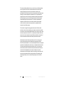
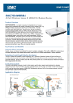
Spatial distribution of electric and magnetic field strength
beneath a 345 kV transmission line
This illustration shows the field distribution for a typical double circuit 345 kV
transmission line carrying 1000 A. The field strengths have been computed for a
height of one meter above the ground from one side of the line to the other and
indicate that the maximum electric field strength beneath the 345 kV line is
expected to be about 3.4 kV/m. The maximum magnetic field strength will be
dependent on the magnitude of current flowing in the line. If the line was carrying
a current of 1000 A, the magnetic fields indicate an expected maximum value of
175 mG (equivalent to 14 A/m).
In addition to the normal variation in field strength which is observed along a line
transverse to the power line, electric fields beneath power lines are perturbed by
the local surroundings. This illustration shows the phenomenon of electric field
concentration which occurs above the head of a person standing under the line.
Localized enhancement of the electric field will lead to decreased field strength in
other nearby areas. Because electric field lines have a tendency to terminate on
grounded objects, and because the human body is conductive and is electrically
near ground potential, there tends to be a concentration of field lines at the top of
the head. This same phenomenon occurs with virtually any grounded object
immersed in the electric field environment of a power line and can be confirmed
through field measurements.
www.ets-lindgren.com
Power Frequency Fields
27
This inherent shielding effect of the body, unless the body is sufficiently distant
from the instrument, can lead to inaccurate measures of the electric field
strength. Depending on the proximity and orientation of the body, the
perturbation effect of the body can lead to either enhanced electric field strength
readings or reduced readings when compared to the true unperturbed field
strength. While in some cases it may be desirable to determine the enhanced
fields near objects, in general, most field measurements should be directed
toward assessing the unperturbed values. For example, unperturbed field
strengths or free space values, are more easily related to internal induced
currents in the body. Induced currents represent one potential dosimetric
measure of electric field exposure.
The illustration on page 25 also suggests that the electric field lines which
terminate on the earth are essentially purely vertically oriented directly beneath
the conductors, but at extended lateral distances from the line there can be some
horizontal component to the field. Thus, in measurements of electric fields near
power lines, it may be important to explore different polarization components of
the field to assess the resultant electric fields at points above the earth.
Measurement of electric field strength under a power line or near any other
source of electric fields may be accomplished by supporting the HI-3638
ELF/VLF Electric Field Meter on a non-conductive tripod. Because of the physical
asymmetry in the displacement current sensor it is imperative that the front side
of the sensor be directed toward the electric field source. In this position, the
electric field lines which are directed downward toward the earth will strike the
correct side of the displacement current sensor resulting in an accurate
measurement of the field strength. In addition, the presence of the operator will
tend to perturb the electric field that is being measured. The operator should
remain approximately one to two times their height away from the HI-3638
sensor.
28
Power Frequency Fields
www.ets-lindgren.com
8.0 Guidelines for EMF Exposure
To provide a means for judging the significance of measured electromagnetic
field emissions found near a VDT, the scientific literature can be examined for
information on suggested exposure or emission limits. The exposure standards
used for the content presented in this manual apply to humans for the purpose of
establishing safe working or living environments where electromagnetic fields
exist. The exposure limits in this manual are those found that correspond most
closely to the predominant frequency range of VDTs. In some cases, the
standards apply to occupational exposure environments and in other cases, to
the general living environment; often standards for this latter case are referred to
as general population or public exposure limits.
Traditional approaches to radiation protection, principally derived from ionizing
radiation protection practices, usually differentiate between occupational and
public exposure. Generally, occupational exposure limits are higher (more
permissive) than public limits. This is because of the greater uncertainties
associated with the general public; in the work place, employees are generally
healthier, and possible exposure to potentially hazardous physical agents is
usually under much better control. For example, employers can inform workers of
situations which should be avoided; this is not the case for the general population
as a whole. Regardless of these considerations, it is informative to examine
some of the recommended exposure guides that apply to different organizations
and/or countries.
www.ets-lindgren.com
Guidelines for EMF Exposure
29
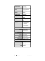
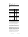
Radio Frequency Exposure / Emission Standards
Pertinent to VDT Frequency Range
Many RF exposure standards are under development or revision. The
following table should be used only as an orientation to existing
standards.
Standard/
Reference
Frequency
(kHz)
ACGIH
0–0.1
0.1–4
4–30
E (V/m)
RMS
25000
2500/f *
625
IEEE C95.1-1991
3–100
614
2.05
50/60 Hz
5000
1.0
0.005–2
2–400
25
2.5
0.0025 (0.25µT)
0.00025 (0.25nT)
UK(1986)(occ)
750 Hz–50 kHz
2000
1.25
UK(1986)(public)
750 Hz–50 kHz
800
0.05
0.03–0.3
25
—
IRPA
(gen. pop. 24 hr)
Swedish
Guidelines **
USSR(public)
(Slesin, 1985)
H (gauss)
RMS
—
0.6/f *
—
* Frequency in kHz
** Guidelines based on what was technically possible, not biological effects
This table summarizes the electromagnetic field exposure standards found in the
literature that either directly apply to the frequency range appropriate to VDT
emissions or pertain to a frequency range close to that of interest. As can be
seen, the primary difficulty in applying many RF exposure standards to VDT
emission levels is that the applicable frequency range of the standards does not
extend down low enough. From the literature searched, only one reference was
found that offered a quantitative emission limit as a guideline specific to VDTs
(Telecom, 1984). This Occupational Health Policy Guideline for screen-based
equipment was developed by Telecom Australia for internal use until such time
as there is a national standard for VDTs in Australia. The guide specifies that the
levels of radiation emitted from cathode-ray VDTs in the frequency range of
50 Hz to 0.3 MHz shall be as low as possible, and should not at any time exceed
an electric field strength of 50 V/m, measured 30 cm from the terminal.
30
Guidelines for EMF Exposure
www.ets-lindgren.com
Appendix A: Warranty
See the Product Information Bulletin included with your shipment for
the complete ETS-Lindgren warranty for your HI-3638.
DURATION OF WARRANTIES FOR HI-3638
All product warranties, except the warranty of title, and all remedies for warranty
failures are limited to one year.
Product Warranted
Duration of Warranty Period
Model HI-3638 ELF/VLF
Electric Field Meter
1 Year
www.ets-lindgren.com
Warranty
31
This page intentionally left blank.
32
Warranty
www.ets-lindgren.com
Appendix B: Operating Protocols
The information in this section is subject to change, and is included for
reference only.
The following information assumes that the HI-4413P Fiber Optic Modem or
HI-4413USB Fiber Optic to USB Converter was purchased and is communicating
directly with the probe.
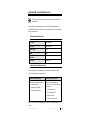
Communication Protocol
Data Type:
RS-232 Serial
Data Mode:
Asynchronous
Word Length:
7 bit
Parity:
Odd
Stop Bits:
1
Data Rate:
9600 baud
Information Transfer Protocol
The probe responds to commands from another device; it transmits no data
without first receiving instructions to do so.
Probe Command Structure
Probe Response Structure
A command to a probe consists of:
When the probe completes the
command, it responds with a string
consisting of:
A command letter
Parameters (if required)
<CR> (a carriage return)
A start character (":")
The command letter
Data (if required)
<CR> (a carriage return)
If an error occurs, the probe responds with an error code. See page 35 for error
codes.
www.ets-lindgren.com
Operating Protocols
33
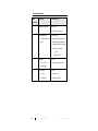
Probe Commands
Probe
Description
Probe Response
Command
B
Read battery voltage
:Bxx.xx<CR>
xx.xx=battery voltage
D1
Read probe data
1 enables short form
output
:Dxx.xxuuu<CR>
xx.xx=reading; the position of
the decimal point depends on
the range setting of the probe
uuu=units; for example,
_V_=V/m
mW2=mW/cm
Rx
Ux
Set range
:Rx<CR>
x=1, 2, 3, 4, or
N (next range)
Rx=range currently in use
Set unit type
:Ux<CR>
x=1, V/m
x=2, mW/cm
34
2
U1=set to V/m
2
Operating Protocols
U2=set to mW/cm
2
www.ets-lindgren.com
Error Codes
If an error occurs, the probe will respond with one of the following strings. These
strings begin with a colon and end with a carriage return.
E1
Communication error (for example, overflow)
E2
Buffer full error; too many characters contained between the
start character and carriage return sequence
E3
Received command is invalid
E4
Received parameter is invalid
E5
Hardware error (for example, EEPROM failure)
E6
Parity error
www.ets-lindgren.com
Operating Protocols
35
This page intentionally left blank.
36
Operating Protocols
www.ets-lindgren.com
Appendix C: References
ACGIH (1987). Threshold limit values for chemical substances in the work
environment adopted by ACGIH with intended Changes for 1987-88. American
Conference of Governmental Industrial Hygienists, Cincinnati.
ANSI (1982). Safety levels with respect to human exposure to radiofrequency
electromagnetic fields, 300 kHz to 100 GHz. American National Standard
C95.1-1982, American National Standards Institute, September 1.
Australia (1985). Maximum exposure levels-radiofrequency radiation-300 kHz to
300 GHz. Australian Standard 2772-1985, Standards Association of Australia,
January 31.
Boivin, W. S. (1986). RF electric fields: VDT's vs. TV receivers. Paper presented
at the International Scientific Conference "Work With Display Units" in
Stockholm, Sweden, May.
Bracken, T.D., W.H. Bailey and J.M. Charry (1985). Evaluation of the DC
electrical environment in proximity to VDT's. Journal of Environmental Science
and Engineering, A20(7), pp. 745-780.
Diffrient, N., A.R. Tilley and D. Harman (1981). Humanscale 7/8/9.
Cambridge, Massachusetts: MIT Press.
FDA (1984). Procedures for laboratory testing of video display terminals and
selected television receivers, monitors and viewfinders. Winchester Engineering
and Analytical Center, Winchester, MA 01890, May.
Germany (1984). Gefahrdung aurch elektromagnetische felder schutz von
personen im frequenzbereich von 10 kHz bis 3000 GHz. VDE 0848 Teil 2,
Deutsche Elektrotechnische Kommission im DIN und VDE (DKE), July.
Grandolfo, M. (1986). Occupational exposure limits for radiofrequency and
microwave radiation, Applied Industrial Hygiene (1), 2, July.
Guy, A.W. (1987). Measurement and analysis of electromagnetic field emissions
from 24 video display terminals in American Telephone and Telegraph office
Washington, D.C. A report prepared for the National Institutes of Occupational
Safety and Health, Cincinnati, March 16.
www.ets-lindgren.com
References
37
Harvey, S.M. (1982). Characteristics of low frequency electrostatic and
electromagnetic fields produced by video display terminals. Ontario Hydro
Research Division report no. 82-528-K, Toronto, Ontario, Canada, December 16.
Harvey, S.M. (1983a). Analysis of operator exposure to electric fields from video
display units. Ontario Hydro Research Division report no. 83-503-k,
Toronto, Ontario, Canada, December 13.
Harvey, S. M. (1983b). Characterization of low frequency magnetic fields
produced by video display units. Ontario Hydro Research Division
report no. 83-504-K, Toronto, Ontario, Canada, November 23.
Harvey, S.M. (1984a). VDU shielding. Ontario Hydro Research Division report
no. 84-327-K, Toronto, Ontario, Canada, October 31.
Harvey, S.M. (1984b). Electric-field exposure of persons using video display
units. Bioelectromagnetics (5), pp. 1-12.
Harvey, S.M. (1985). Risk assessment of VDU electric and magnetic field
exposures. Ontario Hydro Research Division report no. 85-85-K,
Toronto, Ontario, Canada, March 29.
IRPA (1984). Interim guidelines on limits of exposure to radiofrequency
electromagnetic fields in the frequency range from 100-kHz to 300-GHz.
Health Physics (46), 4, pp. 975-984, April.
Joyner, K.H., et al. (1984). Electromagnetic emissions from video display
terminals (VDTs). Australian Radiation Laboratory report ARL/TR067, December.
Mantiply, E.D. (1984). An automated TEM cell calibration system. Report EPA
520/1-84-024, U.S. Environmental Protection Agency, Las Vegas, NV, October
[NTIS order number PB85-134377].
Marha, K. and D. Charron (1983). The very low frequency (VLF) emission testing
of CCOHS video display terminals. Canadian Centre for Occupational Health and
Safety, Hamilton, Ontario, Canada, December.
Mass (1983). Regulations governing fixed facilities which generate
electromagnetic fields in the frequency range of 300 kHz to 100 GHz and
microwave ovens. 105 CMR 122.000, Commonwealth of Massachusetts,
Massachusetts Register, issue no. 379, September.
38
References
www.ets-lindgren.com
MPR (1987). Testing Visual Display Units-test methods, MPR-P 1987:2, National
Council for Metrology and Testing, Stockholm, Sweden, May 15, 1987.
NATO (1979). Control and recording of personnel exposure to radio-frequency
radiation. Standardization Agreement STANAG No. 2345, February 16.
Nylen, P., U. Bergqvist, R. Wibom and B. Knave (1984). Indoor air: Swedish
Council for Building Research, 3, pp. 163-167.
Olsen, W.C. (1981). Electric field enhanced aerosol exposure in visual display
environments. Prepared for the Norwegian Directorate of Labor Inspection.
CMI No. 803604-1.
Paulsson, L.E., et al., (1984). Stralning fran dataskarmar. Report a 84-08,
National Institute for Radiation Protection, Stockholm, Sweden, February 4.
Petersen, R.C., M.M. Weiss and G. Minneci (1980). Nonionizing electromagnetic
radiation associated with video-display terminals, Ocular Effects of Non-ionizing
Radiation, Vol (229) SPIE (Society of Photo-Optical Instrumentation Engineers),
Box 10, Bellingham, Washington 98227 USA, pp. 179-186.
Roy, C.R., et al., (1983). Measurement of electromagnetic radiation emitted from
visual display terminals (VDTs). Australian Radiation Laboratory
report ARL/TR053, Yallambie, Victoria, March.
Slesin, L. (1985). New Soviet Population Standard: 10 uW/cm2 at MW
frequencies. Microwave News (V), 5, June, pp. 1-5.
Stuchly, M.A., D.W. Lecuyer and R.D. Mann (1983). Extremely low frequency
electromagnetic emissions from video display terminals and other devices.
Health Physics, (45), No. 3 (September), pp. 713-722.
Telecom (1984). Telecom Australia occupational health policy & guidelines
screen based equipment. Telecom internal guideline 15.1, Melbourne, Victoria,
September.
Tell, R.A. (1983). Instrumentation for measurement of electromagnetic fields:
equipment, calibration, and selected applications. In Biological Effects and
Dosimetry of Nonionizing Radiation, (Eds., M. Grandolgo, S. Michaelson, and
A. Rindi), NATO Advance Study Institute Series, Series A.: Life Sciences,
Vol. 49, Plenum Publishing Company.
www.ets-lindgren.com
References
39
UK (1986). Advice on the protection of workers and members of the public from
the possible hazards of electric and magnetic fields with frequencies below
300 GHz: a consultative document. National Radiological Protection Board,
Chilton, Didcot, Oxon, United Kingdom, May.
USAF (1987). AFOSH standard 161-9, occupational health, exposure to
radiofrequency radiation, Department of the Air Force, October 12.
USSR (1976). Occupational safety standards electromagnetic fields of
radiofrequency general safety requirements. Official publication
GOST 12.1.006-76 of the State Committee on Standards of the Council of
Ministers of the USSR, Moscow, January 22.
Weiss M.M. and R.C. Petersen (1979). Electromagnetic radiation emitted from
video computer terminals, American Industrial Hygiene Association Journal (40),
pp. 300-309, April.
40
References
www.ets-lindgren.com
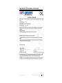
Appendix D: EC Declaration of Conformity
www.ets-lindgren.com
EC Declaration of Conformity
41