1
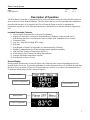
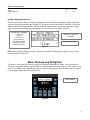
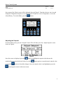
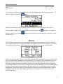
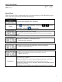
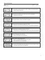
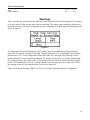
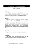
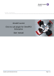
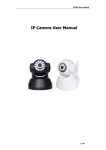
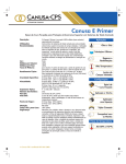
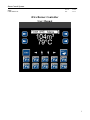
Guest Control Systems
Revision:
Date:
IFIRE
USER MANUAL
00 000
11/07/11
iFire Burner Controller
User Manual
1
Guest Control Systems
Revision:
Date:
IFIRE
USER MANUAL
00 000
11/07/11
Table of Contents
Description of Operation ........................................................................................................................... 3
Included Selectable Features .............................................................................................................. 3
Screen Display ....................................................................................................................................... 3
Ignition Startup Sequence .................................................................................................................... 4
Menu Features and Navigation ............................................................................................................... 4
Adjusting the Setpoint ........................................................................................................................... 5
Historical Trends .................................................................................................................................... 6
Alarm History .......................................................................................................................................... 6
Alarms .......................................................................................................................................................... 7
Alarm Details .......................................................................................................................................... 8
Warnings ................................................................................................................................................... 10
Communications ...................................................................................................................................... 11
2
Guest Control Systems
Revision:
Date:
IFIRE
USER MANUAL
00 000
11/07/11
Description of Operation
The iFire Burner Controller is programmed to be a universal burner controller with selectable options to
meet a variety of needs in most situations. The iFire allows the user to select and adjust the temperature
desired inside the tank. At its simplest, the iFire will turn the flame on and off to maintain the
temperature setpoint as well as shut down the burner if the fluid level in the tank becomes dangerously
low.
Included Selectable Features
1. Level Control (Float Switches or Pressure Transmitter)
2. High Level alarm (Dry Contacts for Skid shutdown or Hydraulic 'pump-to-tank' valve)
3. Auto Restart after Low Level Shutdown (only available with Transmitter Level Control)
4. Continuous Pilot
5. Low Fire / High Fire for High BTU output
6. Soft Start
7. Auto Restart on Flame Fail (adjustable to a minimum delay of 60min)
8. Modbus Communication for Scada including remote shutdown capability
9. 48hr and 24hr Trends on Temperature and Level
10. Alarm history (last 30 alarms) including date and time
11. Operator Adjustable temperature setpoint
12. Auto Restart on Power Cycled
Screen Display
During normal operation the screen will display one of the two home screens depending on the level
monitoring devices in use. If a pressure transmitter is used to determine the level of fluid in the tank than
the home screen is shown in Figure1. If Float Switches are used for level control, the current tank level
is unknown and the home screen is shown in Figure2.
Burner Status
Current Temperature
Current Fluid Level
Figure1: Level Transmitter
Burner Status
Current Temperature
Figure2: Level Switch (Float)
3
Guest Control Systems
Revision:
Date:
IFIRE
USER MANUAL
00 000
11/07/11
Ignition Startup Sequence
The iFire will turn the flame off when the temperature in the tank has reached the operator selectable
setpoint. Once the temperature has dropped 2ºC below the setpoint, the Burner Controller will turn the
flame on and begin heating the tank. During the ignition sequence the screen will display the current
stage of ignition and walk the user through the process. This screen is shown in Figure3.
Current Stage of Ignition:
Pre Purge 30s
Igniting
Purging 15s
Pilot Stabilizing
Main Brnr Soft Start
Main Brn Stabilizing
Main Burner Stable
Number of Ignition
Attempts.
Stage Count Down
Figure3
Note: During Ignition Startup Sequence, the Burner Controller will attempt to ignite the gas 3 times
before going into Flame Fail
Menu Features and Navigation
The menu is accessible to the user by simply pressing the button that the ‘Menu’ word is pointing to.
The only time that the Menu is not reachable is during the Ignition Startup Sequence. The ‘Menu’ word
may be in a different place depending on which screen is being displayed, but the menu can be reached
by pressing the button that is being pointed to.
Menu Button
Figure4
4
Guest Control Systems
Revision:
Date:
IFIRE
USER MANUAL
00 000
11/07/11
Once pressed, the ‘Menu' screen will be displayed shown in Figure5. From here the user can view and
change the Temperature Setpoint, access the Historical Trends for Level or Temperature, or view the
Alarm History. To exit the Menu, press the
button.
Figure5
Adjusting the Setpoint
From the Menu screen, press the ‘Setpoint’ button. This will take you to the ‘Adjust Setpoint’ screen
shown in Figure6.
Figure6
Once this screen is displayed, press the
button to highlight the setpoint value then use the
numbered keys to enter the desired value. Press the
or press the
button again to accept the newly entered value,
button to discard the changes. Once the setpoint value is not highlighted, press the
button again to return to the menu screen.
5
Guest Control Systems
Revision:
Date:
IFIRE
USER MANUAL
00 000
11/07/11
Historical Trends
From the Menu screen, press the ‘Level Trend’ button to view the historical trend of the tank level. This
will take you to the screen shown in Figure7 which shows a graph of the tank level over the past 48
hours.
Figure7
The graph is scaled from 0m³ to 160m³. The operator may also press the ‘24hr’ button to view the tank
levels 24 hour graph. From the 24 hour trend screen press the
screen and from the 48hr trend screen press the
button to return to the 48hr trend
button to return to the menu screen.
To view the historical trends of the tank temperature, press the ‘Temp Trend’ button from the menu
screen. This will display the 48 hour trend of the tank temperature which is scaled from 50ºC to 100ºC.
Navigating the temperature trend screens is the same as the level trend screens.
Alarm History
The iFire Burner Controller records and stores the 30 most recent alarms that have occurred including
the date and time the alarm was triggered. To view the alarm history press the ‘Alarms’ button from the
menu screen. This will display the 6 most recent alarms that have occurred which is shown in Figure8.
Figure8
Once the ‘Alarm History’ screen is displayed the operator may press the
or
up and down and view alarms 1 through 6. The operator can also use the
button to skip to the very
button to scroll
top of the list or use the
button to skip to the bottom of the list. The ‘Alarm History’ screen allows
the operator to view 6 alarms at a time.
6
Guest Control Systems
Revision:
Date:
IFIRE
USER MANUAL
00 000
11/07/11
To view the next 6 alarms go to the bottom of the list and highlight the selection named ‘Alarms 7-12’
shown in Figure9 and press the
button.
Figure9
Now the Alarm History screen will display alarms 7 through 12 and at the bottom of that list is a
selection named ‘Alarms 13-18’. Highlight this selection and press the
through 18 and so on. Press the
the menu screen.
button to view alarms 13
button to go back to the previous alarm group, and also to exit to
Alarms
The iFire Burner Controller has been developed to shut down onsite equipment if an unsafe situation
arises. When an alarm state is triggered an alarm screen appears which is shown in Figure10. The alarm
screen displays the alarm type, what equipment has been shutdown or operator action required.
Figure10
In this case, the alarm type is Power Cycled which means that the controller has lost power and now the
power has been restored. It informs the operator that a reset is required to begin normal operation. Also
displayed on the alarm screen is the current tank level and fluid temperature. The alarm screen only
allows the viewing or resetting of 1 alarm at a time. To view any other alarm that has been triggered
press the button that the ‘Next ALM’ is pointing to. This will cycle the display to the next pending alarm
condition. By pressing this button multiple times the operator can view all pending alarms by cycling
through them. The operator can also get into the menu screen by pressing the button that the ‘Menu’ is
pointing to. From there the Alarm History and Historical Trends may be viewed to provide a more
detailed diagnostics.
7
Guest Control Systems
Revision:
Date:
IFIRE
USER MANUAL
00 000
11/07/11
Alarm Details
There are several ‘Alarm’ states that may result in a burner shutdown or well ESD and this section
details each alarm, what caused it and troubleshooting tips.
iFire has been Halted and is NOT operating
Action
Press
to highlight the “Idle Mode” then use the
“Run Mode” and press
or
to select
again to accept it.
Power has been lost and is now restored
- Note: The Auto Start feature enables the iFire to auto run on a power
cycle
Temperature Transmitter (Thermocouple) Error
- Burner has been shut down
Low fluid level inside the tank (either float switch or transmitter)
- Burner has been shut down
Low fluid level inside the tank has recovered and is now safe
- Burner can be reset.
Description
When using a Level Transmitter there is an ‘Auto Reset’ feature on the Low
Level Recovery parameter.
This means that the iFire can be setup to shutdown the burner on low level
and automatically restart the burner once the level has recovered.
The time delay between recovery and Auto Restart can be adjusted but has a
minimum of 30 minutes.
This feature is not available when using a float switch for level control
8
Guest Control Systems
Revision:
Date:
IFIRE
USER MANUAL
00 000
11/07/11
The temperature inside the tank has reached a dangerously high temperature
- Burner has been shut down
High fluid level inside the tank (either float switch or transmitter)
- Skid has been shut down
The Ignition Module (Fenwal) has failed to respond
The burner has been shutdown remotely (SCADA)
- The burner can’t be reset until the remote source disables the shutdown
The skid has been shutdown remotely (SCADA)
- The skid can’t be restarted until the remote source disables the shutdown
Pressure Transmitter (for level) Error
- Burner and Skid have been shut down
Flame Failed to light during ignition
- Burner will automatically reset and retry ignition
- Reset manually to retry immediately
One or more of the Initial Setup values has been lost or not entered correctly
- The burner and skid have been shutdown
9
Guest Control Systems
Revision:
Date:
IFIRE
USER MANUAL
00 000
11/07/11
Warnings
This is a feature that lets the user know when any value is approaching an alarm setpoint and is intended
to be used with SCADA or some other form of monitoring. This feature can be enabled or disabled by a
qualified technician. The screen will display any active warnings, the High Temperature Warning screen
shown in Figure11.
Figure11
It is important to know that Warnings are NOT Alarms, there are no shutdowns performed and they
auto-clear. For example, in Figure11 the High Temp has been set to 95ºC and the High Temp Warning
has been set to 92ºC. As the Temperature in the tank reaches 92ºC the High Temp Warning screen is
displayed but there are no shutdowns performed. The operator can use the reset switch to acknowledge
this warning and clear the screen, or the screen will auto clear itself after the temperature has dropped
below a 2ºC deadband from the 92ºC warning setpoint. Once the temperature has cooled below to 90ºC
the warning screen will clear and the home screen will be displayed.
There are 4 different warnings: High Level, Low Level, High Temperature and Low Temperature.
10
Guest Control Systems
Revision:
Date:
IFIRE
USER MANUAL
00 000
11/07/11
Communications
The iFire Burner Controller is Modbus ready and can communicate via RS485. The parameters that can
be read and written are described below.
Read ONLY Bits
Description
Modbus Address
Alarm (any alarm active)
43600.01
Burner Flame ON
43600.02
Level Transmitter Failed
43600.03
High Fluid Level
43600.04
Low Fluid Level
43600.05
Temp Transmitter Failed
43600.06
High Temperature
43600.07
Setup Incomplete
43600.08
High Fluid Level Warning
43600.09
Low Fluid Level Warning
43600.10
High Temperature Warning
43600.11
Low Temperature Warning
43600.12
Burner OFF by Remote
43600.13
Engine OFF by Remote
43600.14
Low Fuel Gas Pressure
43600.15
High Fuel Gas Pressure
43600.16
Write ONLY Bits
Modbus Address
Turn OFF Burner Remotely
3600
Turn OFF Engine Remotely
3601
11
Guest Control Systems
IFIRE
USER MANUAL
Revision:
Date:
00 000
11/07/11
Read ONLY Integers (16bit)
Description
Modbus Address
Current Fluid Depth
43601
High Fluid Level Deadband
43602
High Fluid Level Setpoint
43603
Low Fluid Level Deadband
43604
Low Fluid Level Setpoint
43605
Low Level Auto Reset Count Down*
43606
Temperature Setpoint
43607
Current Temperature
43608
High Temperature Setpoint
43609
High Temperature Deadband
43610
Flame Fail Auto Reset Count Down**
43611
High Level Warning Setpoint
43612
Low Level Warning Setpoint
43613
High Temperature Warning Setpoint
43614
Low Temperature Warning Setpoint
43615
Tank Height in inches
43616
Tank Diameter in inches
43617
Level Transmitters Height in inches
43618
Burner Tubes Height in inches
43619
Level Transmitters Range 0-XX psi***
43620
Oil Density (Specific Gravity)
43621
Read ONLY Real (32bit)
Description
Modbus Address
Current Fluid Depth REAL
43651-2
Current Temperature REAL
43653-4
* Low Level Auto Reset Count Down:
Once a Low Level alarm is triggered the iFire may AutoStart after a minimum time delay of 30 minutes (only available if using level transmitter. See Low Level
Safe on Page 8). This register shows minutes left until auto-start.
** Flame Fail Auto Reset Count Down: Once a Flame Failed alarm is triggered the iFire will AutoStart after a minimum time delay of 60 minutes (See ‘Flame Fail’ on Page 10). This register shows
minutes left until auto-start.
*** Level Transmitters Range:
This register shows the range of the pressure transmitter used to
determine fluid level. Standard sites will use a 0-15psi transmitter; however, any transmitter that is
relative to zero may be used. This register shows the top-end range of the pressure transmitter in use. For
example, when using a 0-15psi transmitter this register will show 15, when using a 0-25psi transmitter
this register will show 25. A 10-40psi transmitter cannot be used; it must be relative to zero.
12
Guest Control Systems
Revision:
Date:
IFIRE
USER MANUAL
00 000
11/07/11
Alarm Codes:
0
No Alarm Recorded
1
Temperature Transmitter Error
2
High Temperature
3
Low Level
4
Level Transmitter Error
5
Ignition Module Failed
6
Flame Failed
7
High Level
8
Setup Incomplete
9
Remote Burner Off
10
Remote Skid ESD
11
Power Cycled
12
Low Gas Pressure
13
High Gas Pressure
Alarm History (see alarm code table above)
Description
Modbus Address
Alarm 1 Code
43700
Alarm 1 minute
43701
Alarm 1 hour
43702
Alarm 1 day
43703
Alarm 1 month
43704
Alarm 2 Code
43705
Alarm 2 minute
43706
Alarm 2 hour
43707
Alarm 2 day
43708
Alarm 2 month
43709
----Continues Sequentially---Alarm 29 Code
Alarm 29 minute
Alarm 29 hour
Alarm 29 day
Alarm 29 month
Alarm 30 Code
Alarm 30 minute
Alarm 30 hour
Alarm 30 day
Alarm 30 month
43840
43841
43842
43843
43844
43845
43846
43847
43848
43849
13