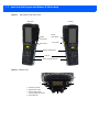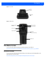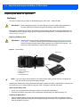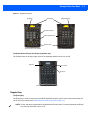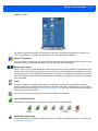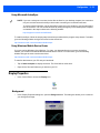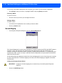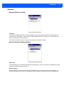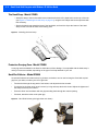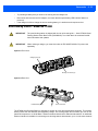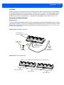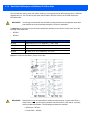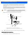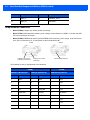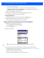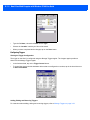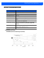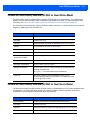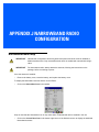
1
OMNII HAND-HELD
COMPUTER
USER GUIDE
for Windows Embedded CE 6.0
i
OMNII HAND-HELD COMPUTER USER GUIDE
(Windows Embedded CE 6.0)
8000211-001
Revision A
April 2015
ii
Omnii Hand-Held Computer with Windows CE 6.0 User Manual
Copyright
No part of this publication may be reproduced or used in any form, or by any electrical or mechanical means,
without permission in writing from us. This includes electronic or mechanical means, such as photocopying,
recording, or information storage and retrieval systems. The material in this manual is subject to change
without notice.
The software is provided strictly on an “as is” basis. All software, including firmware, furnished to the user is on
a licensed basis. We grant to the user a non-transferable and non-exclusive license to use each software or
firmware program delivered hereunder (licensed program). Except as noted below, such license may not be
assigned, sublicensed, or otherwise transferred by the user without prior written consent from us. No right to
copy a licensed program in whole or in part is granted, except as permitted under copyright law. The user shall
not modify, merge, or incorporate any form or portion of a licensed program with other program material, create
a derivative work from a licensed program, or use a licensed program in a network without written permission
from us. The user agrees to maintain our copyright notice on the licensed programs delivered hereunder, and
to include the same on any authorized copies it makes, in whole or in part. The user agrees not to decompile,
disassemble, decode, or reverse engineer any licensed program delivered to the user or any portion thereof.
We reserves the right to make changes to any software or product to improve reliability, function, or design.
We do not assume any product liability arising out of, or in connection with, the application or use of any
product, circuit, or application described herein.
No license is granted, either expressly or by implication, estoppel, or otherwise under any of our intellectual
property rights. An implied license only exists for equipment, circuits, and subsystems contained in our
products.
iii
Disclaimer
Every effort has been made to make this material complete, accurate, and up-to-date. In addition, changes are
periodically incorporated into new editions of the publication.
We reserve the right to make improvements and/or changes in the product(s) and/or the program(s) described
in this document without notice, and shall not be responsible for any damages including, but not limited to,
consequential damages, caused by reliance on the material presented.
Zebra and the Zebra head graphic are registered trademarks of ZIH Corp. The Symbol logo is a registered
trademark of Symbol Technologies, Inc., a Zebra Technologies company.
Workabout Pro4 and the names of other products and services provided by us are trademarks of ours.
Windows® and the Windows Logo are trademarks or registered trademarks of Microsoft Corporation in the
United States and/or other countries.
The Bluetooth® word mark and logos are owned by Bluetooth SIG, Inc. and any use of such marks by us is
under license.
All trademarks used herein are the property of their respective owners.
iv
Omnii Hand-Held Computer with Windows CE 6.0 User Manual
Revision History
Changes to the original guide are listed below:
Change
Rev -001A
Date
04/2015
Description
Zebra rebrand.
Table of Contents
TABLE OF CONTENTS
About This Guide ............................................................................................................................ xi
Text Conventions ............................................................................................................................ xii
Overview of the Omnii Hand-Held Computer.................................................................................. xii
Regulatory Labels ........................................................................................................................... xvi
Chapter 1: Basic Operation
Omnii Features ............................................................................................................................... 1-1
Omnii Modules Available ................................................................................................................ 1-3
Documents Available ..................................................................................................................... 1-3
Preparing the Omnii for Operation .................................................................................................. 1-4
The Battery .....................................................................................................................................1-4
Switching the Omnii On and Off...................................................................................................... 1-5
Resetting the Omnii ........................................................................................................................ 1-5
Performing a Warm Reset..............................................................................................................1-6
Performing a Cold Reset ................................................................................................................1-6
Performing a Clean Start ................................................................................................................1-6
Boot to BooSt..................................................................................................................................1-6
Performing a Hard Reset................................................................................................................1-7
Attaching Carrying Accessories ...................................................................................................... 1-7
Calibrating the Touchscreen ........................................................................................................... 1-7
Imager and Scanner Options .......................................................................................................... 1-7
Connectivity .................................................................................................................................... 1-7
Data Transfer ................................................................................................................................. 1-8
Voice Communication ..................................................................................................................... 1-8
Chapter 2: Getting To Know Your Omnii
Operating System ........................................................................................................................... 2-1
Battery Details................................................................................................................................. 2-1
Battery Safety .................................................................................................................................2-1
Battery Swap Time .........................................................................................................................2-1
Charging the Battery ......................................................................................................................2-2
The Keyboard ................................................................................................................................. 2-2
ii
Omnii Hand-Held Computer with Windows CE 6.0 User Guide
Regular Keys ..................................................................................................................................2-3
Modifier Keys ..................................................................................................................................2-4
Activating Modifier Keys...................................................................................................... 2-5
Locking Modifier Keys ......................................................................................................... 2-5
Function Keys and Macro Keys .....................................................................................................2-6
Function Keys ..................................................................................................................... 2-6
Macro Keys ......................................................................................................................... 2-6
Numeric Keyboards — Accessing Alpha Keys ..............................................................................2-7
The Keypad Backlight.....................................................................................................................2-8
The Display..................................................................................................................................... 2-8
Adjusting the Display Backlight ......................................................................................................2-8
Calibrating the Touchscreen...........................................................................................................2-8
Indicators ........................................................................................................................................ 2-9
LEDs ...............................................................................................................................................2-9
Battery Charge Status LED ................................................................................................. 2-9
Operating System Status LED ............................................................................................ 2-9
Radio Status LED................................................................................................................ 2-10
Scanner Status LED............................................................................................................ 2-10
Onscreen Indicators .......................................................................................................................2-10
Audio Indicators..............................................................................................................................2-12
Vibrations........................................................................................................................................2-12
Inserting the microSD Card and SIM Card ..................................................................................... 2-12
Inserting the Cards .........................................................................................................................2-12
Scanners and Imagers.................................................................................................................... 2-13
Basic Scanner Operations..............................................................................................................2-14
Scanning Techniques .....................................................................................................................2-14
Scanner Status LED, Sounds, and Vibrations ...............................................................................2-14
Troubleshooting ..............................................................................................................................2-15
Operating One Dimensional (1D) Internal Laser Scanners ...........................................................2-15
Operating Internal Two Dimensional (2D) Imagers........................................................................2-15
Windows Embedded CE 6.0........................................................................................................... 2-16
Navigating in Windows Embedded CE and Applications ..............................................................2-16
Navigating Using a Touchscreen ........................................................................................ 2-16
Navigating Using the Keyboard .......................................................................................... 2-17
The Windows Classic Shell Startup Desktop .................................................................................2-18
The Taskbar ........................................................................................................................ 2-19
The Start Menu ................................................................................................................... 2-20
The Kiosk Desktop Shell................................................................................................................. 2-25
Restoring the Windows Classic Shell.............................................................................................2-26
General Maintenance ..................................................................................................................... 2-27
Caring for the Touchscreen ............................................................................................................2-27
Cleaning the Omnii .........................................................................................................................2-27
Chapter 3: Configuration
Overview of Software...................................................................................................................... 3-1
Software Advantage .......................................................................................................................3-1
Table of Contents iii
Microsoft Software..........................................................................................................................3-2
The Control Panel ........................................................................................................................... 3-2
Control Panel Applications .............................................................................................................3-3
App Launch Keys............................................................................................................................ 3-6
Bluetooth® Setup.......................................................................................................................... 3-7
Paired ............................................................................................................................................3-8
Device ............................................................................................................................................3-9
Discovering and Removing Devices ................................................................................... 3-9
Filtering By Class of Device (COD)..................................................................................... 3-10
Device Pop-up Menu........................................................................................................... 3-10
Pairing a Device .................................................................................................................. 3-10
Servers ..........................................................................................................................................3-12
Mode ..............................................................................................................................................3-13
About .............................................................................................................................................3-13
The Bluetooth GPRS WAN Connection .......................................................................................3-14
Certificates ...................................................................................................................................... 3-17
Compass......................................................................................................................................... 3-17
Data Transfer between Omnii and a PC ........................................................................................ 3-18
Uploading Data in a Docking Station..............................................................................................3-18
Using Microsoft ActiveSync............................................................................................................3-19
Using Windows Mobile Device Center...........................................................................................3-19
Display Properties........................................................................................................................... 3-19
Background ...................................................................................................................................3-19
Appearance ...................................................................................................................................3-20
Backlight ........................................................................................................................................3-20
Dr. Debug ....................................................................................................................................... 3-21
Status..............................................................................................................................................3-21
Utilities ............................................................................................................................................3-21
Motion Meter...................................................................................................................................3-22
Settings...........................................................................................................................................3-23
Error Reporting ............................................................................................................................... 3-23
GPS (Global Positioning System) Settings ..................................................................................... 3-23
Power..............................................................................................................................................3-24
Profiles............................................................................................................................................3-24
Programs ........................................................................................................................................3-25
AGPS..............................................................................................................................................3-25
Info..................................................................................................................................................3-26
Imager & Camera Settings ............................................................................................................. 3-26
Input Panel...................................................................................................................................... 3-27
Keyboard Properties ...................................................................................................................... 3-28
Key Repeat.....................................................................................................................................3-29
Keyboard Backlight ........................................................................................................................3-29
Keyboard One Shot Modes............................................................................................................3-30
Keyboard Macro Keys ....................................................................................................................3-31
Unicode Mapping ...........................................................................................................................3-32
Scancode Remapping....................................................................................................................3-33
iv
Omnii Hand-Held Computer with Windows CE 6.0 User Guide
Lock Sequence...............................................................................................................................3-35
Manage Triggers............................................................................................................................. 3-36
Trigger Mappings............................................................................................................................3-36
Add and Edit Trigger Mapping........................................................................................................3-37
Microphone .................................................................................................................................... 3-38
TekTerm Client ................................................................................................................................ 3-39
PartnerUp ....................................................................................................................................... 3-39
Pocket PC Compatibility ................................................................................................................. 3-39
Power Properties ............................................................................................................................ 3-40
Battery Capacity .............................................................................................................................3-40
Power Saving Suspend ..................................................................................................................3-40
Suspend Threshold and Estimated Battery Backup ......................................................................3-41
Advanced .......................................................................................................................................3-42
Built-in Devices ...............................................................................................................................3-42
Battery Health .................................................................................................................................3-43
Kiosk Access .................................................................................................................................. 3-44
Administrator Password..................................................................................................................3-45
Shell Settings..................................................................................................................................3-46
Restrictions ....................................................................................................................................3-48
Control Panel Settings....................................................................................................................3-48
Import/Export to File .......................................................................................................................3-49
Remote Desktop Connection ......................................................................................................... 3-50
Scanners......................................................................................................................................... 3-50
Barcodes ........................................................................................................................................3-51
Scanner............................................................................................................................... 3-51
Restoring Default Settings .................................................................................................. 3-51
Options ..........................................................................................................................................3-52
Double Click Parameters .................................................................................................... 3-53
Display Parameters............................................................................................................. 3-53
Data Handling ..................................................................................................................... 3-54
Translations ...................................................................................................................................3-54
Case Rules ......................................................................................................................... 3-56
Ports ...............................................................................................................................................3-56
Port Replicator Port A (COM5) and Port B (COM6)............................................................ 3-57
Screen Rotation .............................................................................................................................. 3-58
Storage Manager ............................................................................................................................ 3-59
Formatting a Memory Card ............................................................................................................3-59
Creating Partitions ..........................................................................................................................3-59
Partition Management ....................................................................................................................3-60
Stylus Properties............................................................................................................................. 3-62
Double-Tap .....................................................................................................................................3-62
Calibration.......................................................................................................................................3-62
Touch ..............................................................................................................................................3-63
System Properties .......................................................................................................................... 3-63
Total Recall ..................................................................................................................................... 3-64
Creating a Backup ..........................................................................................................................3-64
Creating a Clone.............................................................................................................................3-65
Table of Contents v
Managing Profiles...........................................................................................................................3-66
Viewing a Profile ................................................................................................................. 3-66
Profile Options..................................................................................................................... 3-66
Deleting a Profile ............................................................................................................................3-68
TweakIt............................................................................................................................................ 3-68
Advanced........................................................................................................................................3-69
Advanced CE Services Settings ......................................................................................... 3-69
Advanced Interface and Network Settings .......................................................................... 3-69
Advanced Services Settings ............................................................................................... 3-70
Registry Editor ................................................................................................................................3-70
Voice – Using the WWAN Phone Dialer ......................................................................................... 3-70
Dialing a Number............................................................................................................................3-71
Receiving an Incoming Call............................................................................................................3-72
Voice Menu.....................................................................................................................................3-72
Call Management ................................................................................................................ 3-72
Call Lists.............................................................................................................................. 3-73
Services .............................................................................................................................. 3-74
File Menu – Phonebook Management...........................................................................................3-74
Volume & Sounds Properties .......................................................................................................... 3-75
Volume Adjustments.......................................................................................................................3-76
Sound Adjustments ........................................................................................................................3-76
Wi-Fi Config .................................................................................................................................... 3-76
Wi-Fi Config: Status .......................................................................................................................3-77
Wi-Fi Config: Configure .................................................................................................................3-77
Manually Creating a Network .............................................................................................. 3-78
Authentication Mode ........................................................................................................... 3-78
Encryption ........................................................................................................................... 3-79
EAP .................................................................................................................................... 3-79
Verify Server Certificate ...................................................................................................... 3-80
Enable OPMK ..................................................................................................................... 3-80
Connecting the Wireless Network ....................................................................................... 3-81
Configuring TCP/IP ........................................................................................................................3-82
IP Address........................................................................................................................... 3-82
Name Server ....................................................................................................................... 3-83
Wi-Fi Config: Advanced .................................................................................................................3-84
Monitoring the Network Connection...............................................................................................3-85
WiFi Connect A.R.C........................................................................................................................ 3-85
Chapter 4: Accessories
Pistol Grips...................................................................................................................................... 4-1
Removing the Trigger Cover ..........................................................................................................4-1
Attaching the Pistol Grip.................................................................................................................4-2
Carrying and Protective Accessories ............................................................................................. 4-3
The Hand Strap - Model ST6025 ...................................................................................................4-4
Protective Carrying Case - Model ST6090 ....................................................................................4-4
Hard Shell Holster - Model ST6055 ...............................................................................................4-4
Power Accessories ......................................................................................................................... 4-5
vi
Omnii Hand-Held Computer with Windows CE 6.0 User Guide
Snap Modules................................................................................................................................4-5
AC Wall Adaptor - Models ST1050 and ST1050-AR .....................................................................4-7
Vehicle Power Outlet Adaptor - Model ST3113..............................................................................4-7
Chargers and Docking Stations: General Information .................................................................... 4-8
Important Charger Safety Instructions............................................................................................4-8
Charging the Battery.......................................................................................................................4-8
Installation — Chargers and Docking Stations...............................................................................4-8
Operator Controls ...........................................................................................................................4-9
Power Consumption Considerations..............................................................................................4-9
Desktop Docking Stations - Models ST4002 and ST4003 .............................................................. 4-9
Charging a Battery Installed in the Omnii.......................................................................................4-11
Indicators ........................................................................................................................................4-11
Operation .......................................................................................................................................4-11
Charging the Omnii Battery................................................................................................. 4-11
Charging the Spare Battery................................................................................................. 4-11
Cleaning the Desktop Docking Station...........................................................................................4-12
Troubleshooting ..............................................................................................................................4-12
Docking station does not seem to power on. ...................................................................... 4-12
The Omnii charge indicator LED stays off........................................................................... 4-12
The Omnii charge indicator LED is red. .............................................................................. 4-12
Spare battery LED is red with a battery installed. ............................................................... 4-12
Spare battery LED does not turn on when a battery is installed. ........................................ 4-12
Quad Docking Station – Model No. ST4004 ................................................................................... 4-13
Operator Controls ...........................................................................................................................4-14
Indicators ........................................................................................................................................4-14
Quad Docking Station Operation....................................................................................................4-14
Charging the Omnii Battery................................................................................................. 4-14
Installation ........................................................................................................................... 4-15
Connecting to the Ethernet Network ................................................................................... 4-15
Cleaning the ST4004......................................................................................................................4-16
Troubleshooting ..............................................................................................................................4-16
The Omnii Charge Indicator LED Stays Off ........................................................................ 4-16
Power LED Does Not Light Up ........................................................................................... 4-16
The Omnii Charge LED Flashes Yellow.............................................................................. 4-16
The Omnii Charge Indicator LED is Red............................................................................. 4-16
Powered Adaptor LED Stays Off......................................................................................... 4-16
Vehicle Cradles - Models ST1000 and ST1002 ............................................................................ 4-16
Vehicle Cradle Mounting Recommendations ................................................................................4-17
Insertion and Removal of Omnii.....................................................................................................4-19
Maintaining the Vehicle Cradle.......................................................................................................4-20
ST1002 Powered Cradle Installation..............................................................................................4-20
Wiring Guidelines................................................................................................................ 4-20
Installation in High Voltage Vehicles ................................................................................... 4-21
Wiring Vehicle Power and Communications to the Cradle.................................................. 4-21
Battery Charger (6-Slot) - Model ST3006 ....................................................................................... 4-22
Installation.......................................................................................................................................4-23
Operator Controls ...........................................................................................................................4-24
Table of Contents vii
Charge Indicators ...........................................................................................................................4-24
Charging Batteries..........................................................................................................................4-24
Troubleshooting..............................................................................................................................4-24
Improper Battery Storage .................................................................................................... 4-24
Power Self-test LEDs Don’t Light Up .................................................................................. 4-25
Indicator Does Not Light When Battery Installed ................................................................ 4-25
Appendices
Appendix A: Port Pinouts
Omnii Docking Connector ............................................................................................................... A-1
Snap Modules Connectors.............................................................................................................. A-2
Cable Connectors for Vehicle Cradle Model ST1002 ..................................................................... A-3
Omnii Battery Contacts ................................................................................................................... A-4
Appendix B: Imager & Camera Settings
Introduction ..................................................................................................................................... B-1
Required Applets ............................................................................................................................ B-1
Presets ........................................................................................................................................... B-1
Predefined Presets ................................................................................................................... B-2
Barcode Predefined Presets (Barcoding Menu)........................................................................ B-2
Barcode Decoding Symbology Predefined Presets ............................................................ B-2
Barcode Decoding Camera Predefined Presets ................................................................. B-3
Image Capture Predefined Presets (Imaging Menu)................................................................. B-3
Using the Imagers Applet................................................................................................................ B-3
Configuring the Image Capture Presets (Imaging Menu).......................................................... B-3
Selecting a Camera............................................................................................................. B-4
Setting the Active Preset..................................................................................................... B-4
Viewing a Preset ................................................................................................................. B-4
Creating a Custom Preset................................................................................................... B-5
Modifying a Custom Preset ................................................................................................. B-5
Removing a Custom Preset ................................................................................................ B-6
Configuring the Barcode Decoding Camera Presets (Barcoding Menu)................................... B-6
Selecting a Camera............................................................................................................. B-7
Setting the Active Preset..................................................................................................... B-7
Viewing a Preset ................................................................................................................. B-7
Creating a Custom Preset................................................................................................... B-7
Modifying a Custom Preset ................................................................................................. B-8
Removing a Custom Preset ................................................................................................ B-8
Configuring the Barcode Decoding Symbologies (Barcoding Menu) ........................................ B-9
Setting the Active Preset..................................................................................................... B-9
Viewing a Preset ................................................................................................................. B-9
Creating a Custom Preset................................................................................................... B-10
Modifying a Custom Preset ................................................................................................. B-10
Removing a Custom Preset ................................................................................................ B-11
Barcoding Menu – Configuring Symbologies ............................................................................ B-11
Symbology Settings ............................................................................................................ B-11
Filter Menu – Manipulating Barcode Data................................................................................. B-12
viii
Omnii Hand-Held Computer with Windows CE 6.0 User Guide
Modifying a Barcode Setting ............................................................................................... B-12
Translation Menu – Configuring Rules...................................................................................... B-13
Advanced Menu ........................................................................................................................ B-13
File Locations for Captured Images .................................................................................... B-13
Configuring Triggers............................................................................................................ B-14
Barcode Symbologies..................................................................................................................... B-15
Imager Barcode Symbologies................................................................................................... B-16
Color Camera Barcode Symbologies........................................................................................ B-17
Appendix C: Scanner Settings
Barcode Settings ............................................................................................................................ C-1
Scanner Options ....................................................................................................................... C-1
Restoring Default Settings ........................................................................................................ C-2
Decoded (Internal) Scanners.......................................................................................................... C-3
Options...................................................................................................................................... C-3
Decoded (Internal) Advanced Options...................................................................................... C-4
Decoded (Internal) Data Options .............................................................................................. C-5
Decoded (HHP) .............................................................................................................................. C-6
Decoded (Intermec ISCP)............................................................................................................... C-6
Decoded (ISCP) Options .......................................................................................................... C-7
Decoded (ISCP) Advanced Options ......................................................................................... C-7
Non-Decoded Scanners ................................................................................................................. C-8
Options...................................................................................................................................... C-9
Appendix D: Internal Imager & Scanner Specifications
SE955 Scanner............................................................................................................................... D-1
SE955 Decode Zones............................................................................................................... D-2
SE965 Scanner............................................................................................................................... D-2
SE965 Decode Zones............................................................................................................... D-3
SE1224HP - High Performance Scanner ....................................................................................... D-4
SE1224HP Decode Zones........................................................................................................ D-4
SE1524ER – Extended Range Scanner......................................................................................... D-5
SE1524ER Decode Zones........................................................................................................ D-5
SE1524ER Decode Zone A (Short Range, Small Codes) .................................................. D-5
SE1524ER Decode Zone B (Long Range, Large Codes)................................................... D-6
EV15 Imager................................................................................................................................... D-6
EV15 Imager Decode Zone ...................................................................................................... D-6
EA11 Decoded 2D Imager .............................................................................................................. D-7
EA11 Typical Reading Distances .............................................................................................. D-7
EA20X Imager ................................................................................................................................ D-8
EA20X Typical Reading Distances ........................................................................................... D-9
HHP 5080SR Imager/Decoder ....................................................................................................... D-9
HHP 5080SR Working Range................................................................................................... D-10
SE4500SR – Standard Range Imager............................................................................................ D-10
SE4500SR Decode Zone.......................................................................................................... D-12
SE4600LR – Long Range Imager................................................................................................... D-13
SE4600LR Decode Zones ........................................................................................................ D-15
Table of Contents ix
Appendix E: Omnii Specifications
The Omnii Hand-Held Computer (Model 7545) .............................................................................. E-1
Hardware .................................................................................................................................. E-1
Regulatory Approvals................................................................................................................ E-3
Lithium-ion Smart Battery 5000 mAh (ST3003) .............................................................................. E-4
Wireless Radios .............................................................................................................................. E-5
Cinterion MC75i GSM/GPRS/EDGE Radio .............................................................................. E-5
Cinterion PH8-P GSM/GPRS/EDGE/UMTS/HSPA+ Radio ...................................................... E-6
Model RA2070 802.11a/b/g/n Radio ......................................................................................... E-8
Bluetooth Radio ....................................................................................................................... E-10
RA1202 Narrowband Radio ...................................................................................................... E-10
Appendix F: Omnii XT15f Freezer Variants
The Omnii XT15f Hand-Held Computer (Model 7545XT) ............................................................... F-1
Hardware Specifications ........................................................................................................... F-2
Regulatory Approvals................................................................................................................ F-4
The Freezer Keyboards ............................................................................................................ F-4
Lithium-ion Smart Battery 5000 mAh (ST3003) for Omnii Chiller Model ........................................ F-5
Lithium-ion Smart Battery 5300 mAh (ST3002) for Omnii Arctic Model.......................................... F-5
Quick Defrost Application................................................................................................................ F-6
Settings ..................................................................................................................................... F-7
Heater Info ................................................................................................................................ F-8
Appendix G: Wireless Wide Area Network (WWAN) Settings
Wireless WAN ................................................................................................................................. G-1
Taskbar Icons............................................................................................................................ G-1
Establishing a Packet Data Connection .................................................................................... G-2
Disconnecting From a Network ........................................................................................... G-3
Shutting Down the Wireless WAN User Interface ............................................................... G-3
Advanced Information ............................................................................................................... G-4
Entering a PIN Number ....................................................................................................... G-4
Error States ......................................................................................................................... G-4
Tools Menu................................................................................................................................ G-5
WWAN Data Configuration.................................................................................................. G-5
Security Configuration......................................................................................................... G-8
Network Configuration......................................................................................................... G-9
Driver Mode Configuration ................................................................................................. G-10
Modem Information ............................................................................................................. G-11
User Interface...................................................................................................................... G-12
AT Terminal ......................................................................................................................... G-13
SMS Menu ............................................................................................................................... G-13
New ..................................................................................................................................... G-13
Inbox ................................................................................................................................... G-13
Outbox................................................................................................................................. G-14
SMS Configuration .............................................................................................................. G-14
Voice ......................................................................................................................................... G-14
Power Mode.................................................................................................................................... G-14
Table of Contents x
Appendix H: Wireless Zero Config Settings
Wireless Information ....................................................................................................................... H-1
Wireless Statistics .................................................................................................................... H-2
Wireless Information ................................................................................................................ H-2
Assigning An IP Address ................................................................................................................ H-5
Name Server............................................................................................................................. H-5
Advanced Features......................................................................................................................... H-5
Rearranging Preferred Networks .............................................................................................. H-5
Deleting A Preferred Network ................................................................................................... H-5
Changing Network Properties ................................................................................................... H-6
Appendix I: Omnii XT15ni Non-Incendive Safety Guidelines
Omnii XT15ni (non-incendive) Important Safety & Regulatory Information .................................... I-1
Omnii XT15ni Battery Information................................................................................................... I-2
Appendix J: Narrowband Radio Configuration
Narrowband Radio Setup................................................................................................................ J-1
Basic Tab ........................................................................................................................................ J-2
Channels Tab .................................................................................................................................. J-3
Advanced Tab ................................................................................................................................. J-6
Tune Poll Settings ........................................................................................................................... J-6
Statistics Screen ............................................................................................................................. J-6
Index. . . . . . . . . . . . . . . . . . . . . . . . . . . . . . . . . . . . . . . . . . . . . . . . . . . . . . . . . .. . . . . . . . . . . . . . . . . . . . . . . . . . . . . . . . . . . . . . . . . . . . . . . . . . .I
ABOUT THIS GUIDE
ABOUT THIS GUIDE
About This Guide
This guide applies to the following models:
• 7545MBW
• 7545MBWP
• 7545MBWPT
• 7545MBWT
• 7545MBWN
• FCC ID: GM37545MBW, GM37545MBWM and GM37545MBWP
• IC: 2739D-7545MBW and 2739D-7545MBWP
This user guide describes the configuration, operation, and maintenance of the Omnii Hand-Held Computer.
Chapter 1: Basic Operation. describes the steps required to get the Omnii ready for operation.
Chapter 2: Getting To Know Your Omnii. describes Omnii features, including how to charge and maintain
the battery, the keyboard features, the display, using the internal scanner, etc. This chapter also
describes the Microsoft® Windows® Embedded CE 6.0 desktop, and how to change the appearance and actions of the desktop from Windows Classic Shell to the Kiosk Shell.
Chapter 3: Configuration. describes the programs and applications accessed through two main areas from
the Desktop Start Menu: Programs and Settings>Control Panel. The software includes both Zebra
Software Advantage and Microsoft programs, and details how to use them to configure the Omnii,
along with scanners/imagers, Bluetooth, etc. This chapter also details the Kiosk program, which
enables you to customize your computer settings.
Chapter 4: Accessories. describes the peripherals and accessories available for your Omnii computer.
Appendix A: Port Pinouts. describes the Omnii and accessories pinouts.
Appendix B: Imager & Camera Settings. describes in detail your imager’s settings.
Appendix C: Scanner Settings. details your barcode options.
xii
Omnii Hand-Held Computer with Windows CE 6.0 User Manual
Appendix D: Internal Imager & Scanner Specifications. lists the specifications for the Omnii scanners and
imagers.
Appendix E: Omnii Specifications. lists the specifications for your Omnii computer, radios, and battery.
Appendix F: Omnii XT15f Freezer Variants. describes the hardware and heating software of the freezer
units.
Appendix G: Wireless Wide Area Network (WWAN) Settings. describes WWAN configuration information.
Appendix H: Wireless Zero Config Settings. outlines the steps used to configure your radio using Windows
Zero Config.
Appendix I: Omnii XT15ni Non-Incendive Safety Guidelines. lists the approvals, important warnings, and
cautions for the Omnii XT15ni (non-incendive) Hand-held Computer.
Appendix J: Narrowband Radio Configuration. describes setting up the RA1202 Narrowband radio.
Text Conventions
NOTE Notes highlight additional helpful information.
IMPORTANT
WARNING!
These statements provide particularly important instructions or additional information that is critical to the operation of the equipment.
These statements provide critical information that may prevent
physical injury, equipment damage or data loss.
Overview of the Omnii Hand-Held Computer
The Omnii Hand-Held Computer is a modular, industrial hand-held computer. A variety of options are available
to suit applications in courier/delivery, field service, manufacturing facilities, material handling applications in
warehouses, ports and yards, with a focus on real time wireless data transactions. Barcode input methodologies are supported by a variety of available scanners. Optimization for specific operational environments is
also supported with a wide range of peripheral options and carrying accessories.
The Omnii XT15f (Freezer Variant) combines modularity, customizability and performance with added technology to resist condensation for use in cold, condensing environments. For details, see Appendix F: Omnii
XT15f Freezer Variants.
NOTE The Omnii Hand-Held Computer is a body worn device, and to maintain compliance
with the FCC RF exposure guidelines, use a Zebra approved carrying case. Use of
non-approved accessories may violate FCC RF exposure guidelines.
NOTE For product specifications, refer to Appendix E: Omnii Specifications.
About This Guide
xiii
Model Variants
•
Omnii RT15 Hand-Held Computer (rugged) - Model 7545XC
•
Omnii XT15 Hand-Held Computer (extremely rugged) - Model 7545XA
•
Omnii XT15f (Freezer Variant) Hand-Held Computer (extremely rugged) - Model 7545XT
Processor and Memory
•
Texas Instruments® Sitara AM37xx, ARM Processor 800 MHz (OMAP3® compatible)
•
Flash ROM: 1 GB
•
RAM: 512 MB
•
3 axis accelerometer
Operating System
•
Microsoft® Windows® Embedded CE 6.0
Bundled Applications
•
Internet Explorer® 6
•
Windows Mobile Device Center
•
WordPad®, ActiveSync®
Supported Applications*
•
TekTerm Client - Terminal Emulation
•
Wavelink TN - Terminal Emulation
* Note that Tekterm Client is the only application available when a Narrowband radio is installed in the unit.
Device Management and Utilities
•
Kiosk
•
Total Recall, TweakIt, Dr. Debug – Utilities
•
SOTI MobileControl – Mobile Device Management
- Easy configuration management and provisioning platform.
- Powerful remote control and troubleshooting functionality.
- Integrated real time geofencing and location services.
- Advanced device security, user authentication and lockdown features.
User Interface
•
Colour/Touch Display 9.4 cm (3.7 in) diagonal
- VGA (640 x 480) Transflective
- High visibility option: superior sunlight visibility with 165 cd/m2 brightness
- Extreme Duty option: withstands 1.25 Joule impact, superior low temperature operation (to -20° C/-4° F),
with 160 cd/m2 brightness. Better abrasion resistance.
•
Touchscreen
- Passive stylus or finger operation; pan and flick gestures supported
- Signature capture
•
Keyboards
xiv
Omnii Hand-Held Computer with Windows CE 6.0 User Manual
- Large selection of backlit keypads in both alpha and numeric formats. For a list of currently
available keyboard configurations, consult your Zebra representative, or go to:
http://www.zebra.com/US-EN/Product+Lines/Psion/?WT.mc_id=psion_us_p_handheld
•
Voice, Audio & Feedback
- High volume beeper: 95 dBA
- Integrated microphone and speaker
- Optional Push-to-Talk Speaker
•
Walkie-talkie style Push-to-Talk – VoIP over WiFi or WWAN
•
Vibration feedback
Wireless Connectivity
•
Integrated Bluetooth® V2.0 + EDR
•
Integrated 802.11a/b/g/n WiFi
•
Bluetooth® coexistence
•
CCX v4
•
Optional SIRF III GPS Receiver
•
Optional GPS/GPRS/EDGE WWAN radio
•
Optional GPS/GPRS/EDGE with UMTS/HSPA+ WWAN radio
•
Optional RA1202 Narrowband radio
NOTE 802.11b/g and Bluetooth are available simultaneously.
The following figures illustrate the main features of the Omnii — for detailed views, please see Omnii Features
on page 1-1.
About This Guide
Figure 1
Figure 2
Omnii XT15 and RT15 Alphanumeric Variants
Omnii XT15
Omnii RT15
59-Key ABC Keyboard
55-Key ABC Keyboard
Omnii XT15f Freezer Variants
Alphanumeric
Numeric
xv
xvi
Omnii Hand-Held Computer with Windows CE 6.0 User Manual
Figure 3
Figure 4
Bottom View (Docking Connector)
Top View (Scanner Window)
Laser Aperture
Regulatory Labels
Figure 5
Laser Warning Label
WARNING!
Using controls or adjustments or performing procedures other than
those specified herein may result in hazardous radiation exposure.
This label is affixed below the scanner window.
Figure 6
SE955 Laser Warning Label
About This Guide
Figure 7
SE965 and SE4500 Laser Warning Label
Figure 8
LED Radiation Notice Label
Figure 9
SE4600 Laser Warning Label
Thi l b l i
ffi d b l
th
i d
xvii
CHAPTER 1 BASIC OPERATION
BASIC OPERATION
1
Omnii Features
Figure 1-1 Front View of the Omnii XT15 Model with Alphanumeric Keyboard
Speaker
LEDs
Beeper
Display
Scan Key
Microphone
SYM Key
FN Modifier Key
Enter/Power Key
NOTE The Omnii 55- and 66-key keyboards are equipped with a Power button as
shown in Figure 1-1 Front View of the Omnii XT15 Model with Alphanumeric
Keyboard on page 1-1.
1-2
Omnii Hand-Held Computer with Windows CE 6.0 User Guide
Figure 1-2
Side Views of the Omnii XT15
Left Side
Right Side
Vertical
scroll button
Volume
rocker button
Scan button
Enter button
Battery release button
Side rail
Slot for Snap Module arm
Figure 1-3 Bottom View
1
2
1 - Docking Connector
3
2 - Alignment Pin Holes
3 - M2.5 Locking Screws
(for firmly attaching devices)
4 - Hand Strap Slot
2
3
4
Basic Operation 1 - 3
Figure 1-4 Top View
Laser
Aperture
End-Cap
Figure 1-5 Back View
Rear PTT Speaker
(optional)
Camera Aperture
Scanner Window
Scanner Pod
Expansion Back
Pistol Grip
Attachment Screws (4)
Battery Pack
Omnii Modules Available
To see a current list of Omnii accessories and modules, please go to the website at:
http://www.motorlolasolutions.com/US-EN/Product+Lines/Psion/?WT.mc_id=psion_us_p_handheld
Documents Available
To see a current list of documents and download what you need, please go to the Knowledge Base on the
IngenuityWorking community website:
http://www.ingenuityworking.com/knowledge/w/knowledgebase/product-manuals.aspx
1-4
Omnii Hand-Held Computer with Windows CE 6.0 User Guide
Preparing the Omnii for Operation
The Battery
The Omnii is powered by a Lithium-ion Smart Battery pack, 5000 mAh — Model ST3003.
IMPORTANT
Before charging the battery, it is critical that you review the battery safety guidelines in
the Omnii Hand-Held Computer Regulatory & Warranty Guide (PN 8000191).
Battery packs shipped from the factory are charged to approximately 40% and must be fully charged prior to
use. Batteries can be charged using a variety of chargers and docking stations. For detailed information, see
Battery Details on page 2-1.
Replacing the Battery Pack
IMPORTANT
Always switch the unit off before changing the battery (see Switching the Omnii On and
Off on page 1-5). However, assuming the default power saving parameters and battery
reserve level have not been altered, battery swap time is a minimum of 4 minutes — you
will not lose data if the battery is replaced within this time frame.
Figure 1-6 Omnii Battery
Battery Top
1
2
4
Contacts
1
1 - Release button
2 - Battery compartment
3 - Guide tabs
4 - Release button tabs
3
4
Battery bottom
3
3
NOTE If you are using a docking station or an external power supply, you can insert an uncharged battery and use the device while the battery charges.
Assuming the default power saving parameters and battery reserve level have not been altered, a battery can
be removed for up to 4 minutes without losing data. After 4 minutes the terminal may reboot.
Removing the Battery Pack
•
If your unit is equipped with a hand strap, unhook it from the base of the battery.
•
Press the two buttons at the sides of the compartment simultaneously, and slide the battery out.
Installing the Battery Pack
•
Slide the charged battery with the contoured plastic facing you into the unit with the contacts matching
position and the guide tabs moving into the corresponding slots at the base of the compartment. Click both
sides of the battery into place.
Basic Operation 1 - 5
•
If your computer is equipped with a hand strap, re-attach the clip to the slot at the base of the battery.
•
Switch the unit on (see Switching the Omnii On and Off on page 1-5).
Switching the Omnii On and Off
Follow the instructions below for your Omnii. If your keyboard has a power button (55- and 66-key keyboards
only), press that instead of the [FN]+[Enter/Power] key combinations described.
Switching the Omnii On
•
Press and hold down the [Enter/Power] key for at least one second.
When the unit is turned off, normally it automatically enters a power-saving, “suspend” state. When the Omnii
is switched on from the suspend state, within a few seconds operation resumes in the screen in which you
were working prior to turning the computer off.
IMPORTANT
If your Omnii fails to power up, consider the following troubleshooting options:
The battery may be overheated (>60C°), a non-Zebra battery may be installed, or the
battery may have fallen below the configured Suspend Threshold. See Suspend Threshold and Estimated Battery Backup on page 3-41 for details.
To switch on the hand-held, you will need to replace the overheated battery.
However, if you supply AC power to the Omnii with a battery that falls below the
configured Suspend Threshold, the unit will switch on.
Switching the Omnii Off
•
To switch off the Omnii, press the [FN] key and then press and release the [Enter/Power] button. The
Omnii will automatically enter the Suspend state.
IMPORTANT
Turning off the hand-held does not result in a complete shutdown; rather, the unit enters
a power-saving, “suspend” state. When the Omnii is turned on from suspend state, operation resumes within a few seconds.
IMPORTANT
If the word ‘FN’ is displayed underlined in the taskbar area at the bottom of the screen,
this key is locked “on” and the Omnii will not switch off. Press the [FN] key twice followed
by [Enter/Power] to switch the Omnii off.
However, if you’ve set the mode to “Lock” (see Keyboard One Shot Modes on page 3-30),
the Omnii can be turned off even when the [FN] key is locked ‘on’.
Resetting the Omnii
To perform a warm or cold reset, you can access the menu by going to Start>Shutdown. Alternatively you can
use the keyboard shortcuts described below.
NOTE If your Desktop is switched to the Kiosk Shell (refer to The Kiosk Desktop Shell on page 2-25),
resetting the unit is done solely by use of the keyboard shortcuts.
1-6
Omnii Hand-Held Computer with Windows CE 6.0 User Guide
Performing a Warm Reset
During a warm reset, running programs are halted. The contents of the file system, RAM Disk, Flash Disk, and
the registry are preserved.
• Press and hold down the [FN] key and the [Enter/Power] key simultaneously for a minimum of
four seconds.
NOTE You need to reset your Omnii after configuring the radio by switching between Windows Zero
Config and WiFi Config.
Performing a Cold Reset
A cold reset reinitializes all hardware. All RAM including the RAM Disk is erased. Non-volatile storage such as
the Flash Disk is preserved, as is the file system.
To execute a cold reset:
• Press and hold down the [SYM] key, the [FN] key, and the [Enter/Power] key, simultaneously for a
minimum of four seconds.
NOTE As part of the normal Windows Embedded CE cold boot process, the screen may go blank for a
few seconds after the splash screen loading bar reaches the end. The desktop is displayed after
a few moments.
Performing a Clean Start
A clean start returns the Omnii to factory settings, flushes the registry keys, and deletes volatile storage and
the file system. The Flash Disk is preserved.
•
Press and hold down the [FN] key, the [Enter/Power] button and the [SCAN] key simultaneously for a
minimum of six seconds.
The Omnii displays the Boot to BooSt menu.
•
On an alpha keyboard, type .clean.
•
On a numeric keyboard, type .25326.
Boot to BooSt
If you choose Boot to BooSt, the BooSt menu is loaded.
•
Press and hold down the [FN] key, the [Enter/Power] button and the [SCAN] key for a minimum of four
seconds.
Basic Operation 1 - 7
•
Press [1] to launch the OS.
Performing a Hard Reset
IMPORTANT
This procedure is recommended as a last resort, when all other methods fail.
To execute a hard reset:
•
Remove the battery.
•
Using a coin, or other conductive item, connect pins 5 and 6 of the battery contacts for at least six seconds.
Pin 6
•
Pin 5
Replace the battery and power Omnii on. The terminal will boot as if from a cold reset.
Attaching Carrying Accessories
Zebra recommends that a carrying accessory — a hand strap — be installed on the Omnii before use. For
detailed information, please see Carrying and Protective Accessories on page 4-3.
Calibrating the Touchscreen
NOTE The touchscreen function can be turned off (see Touch on page 3-63).
The Omnii touchscreen feature is factory-calibrated and ready-to-go; however, over time the touchscreen's
operating parameters may change, and it may need to be recalibrated for correct operation. Refer to Calibrating the Touchscreen on page 2-8 for details.
Imager and Scanner Options
If your Omnii is equipped with an internal imager or scanner, please review the relevant sections: Appendix B:
Imager & Camera Settings and Appendix C: Scanner Settings for details.
Appendix B: Imager & Camera Settings lists their current model numbers, descriptions, and specifications.
Connectivity
For information on connecting the Omnii to a PC, please refer to Data Transfer between Omnii and a PC on
page 3-18.
1-8
Omnii Hand-Held Computer with Windows CE 6.0 User Guide
The Omnii contains an integrated 802.11a/b/g/n radio module. The Wi-Fi Config application is used to
configure the radio for one or more wireless network profiles. To configure the radio, follow the steps outlined
under the heading Wi-Fi Config on page 3-76.
To configure your Bluetooth settings, please go to Bluetooth® Setup on page 3-7.
If you have a GPS (Global Positioning System) module, you can choose from a set of GPS profiles built into
the modem and set up AGPS (Assisted Global Positioning System). See GPS (Global Positioning System)
Settings on page 3-23.
The Omnii is available with one of the following Wireless WAN radio options: the Cinterion MC75i EDGE and
the Cinterion PH8-P HSPA+. See Appendix E: Omnii Specifications for full specifications. With either of these
radios and a SIM card, you can wirelessly transfer data (see Appendix G: Wireless Wide Area Network
(WWAN) Settings), and you can use the Omnii voice option to place phone calls (see Voice Communication on
page 1-8 below).
To see the radio specifications, please go to Wireless Radios on page E-5.
Data Transfer
Data transfer options vary slightly depending on the type of operating system installed in your PC. Various
options exist depending on whether you are using Windows XP or earlier, Windows Vista®, Windows 7 or later.
For connection details, please refer to Data Transfer between Omnii and a PC on page 3-18.
Voice Communication
If the MC75i EDGE or the Cinterion PH8-P HSPA+ WWAN radio modem is installed and enabled, the Phone
icon and the GSM signal strength icon will appear automatically on the taskbar. For details on using your Voice
options, please refer to Voice – Using the WWAN Phone Dialer on page 3-70.
NOTE The voice option is not available in North America for the MC75i EDGE radio.
CHAPTER 2 GETTING TO KNOW YOUR
OMNII
GETTING TO KNOW YOUR OMNII
2
Operating System
•
Microsoft® Windows® Embedded CE 6.0
Battery Details
Omnii Hand-Held Computers are powered by a lithium-ion battery pack, Model ST3003.
Please see the following sections for detailed battery information:
•
Installation: Preparing the Omnii for Operation on page 1-4.
•
Calibration and power settings: Power Properties on page 3-40.
•
Chargers and docking stations: Chapter 4: Accessories.
•
Specifications: Lithium-ion Smart Battery 5000 mAh (ST3003) on page E-4.
•
Contact pinout: Omnii Battery Contacts on page A-4.
Battery Safety
IMPORTANT
Before attempting to install, use, or charge the battery pack, it is critical that you review
and follow the important safety guidelines in the quick reference guide entitled the Omnii
Hand-Held Computer Regulatory & Warranty Guide, PN 8000191.
Battery Swap Time
Assuming the default power saving parameters and battery reserve level have not been altered, battery swap
time is a minimum of 4 minutes — you will not lose data if the battery is replaced within this time frame.
To protect data, the safest place to store data is on a microSD memory card or externally to the device on a
USB memory stick or on a PC. You can also save data in the “Flash Disk” partition of the file system.
Refer to Suspend Threshold and Estimated Battery Backup on page 3-41 for details about reserving battery
power for data backup purposes.
The Suspend Threshold adjustment in the Power Properties tab allows you to determine the battery capacity at
which the Omnii will be shut down. If left at the default value, Maximum Operating Time, the unit will run until
2-2
Omnii Hand-Held Computer with Windows CE 6.0 User Guide
the battery is completely empty; the RAM is only backed up for a short period of time. If you choose Maximum
Backup Time, the Omnii shuts off with more energy left in the battery so RAM can be backed up for a longer
period of time.
IMPORTANT
If your Omnii fails to power up, consider the following troubleshooting options:
The battery may be overheated (>60C°), a non-Zebra battery may be installed, or the
battery may have fallen below the configured Suspend Threshold. See Suspend Threshold and Estimated Battery Backup on page 3-41 for details.
To switch on the hand-held, you will need to replace the overheated battery.
However, if you supply AC power to the Omnii with a battery that falls below the
configured Suspend Threshold, the unit will switch on.
Charging the Battery
Batteries shipped from the factory are charged to approximately 40% of capacity. Lithium-ion battery packs
must be fully charged before use. These batteries can be charged with a variety of chargers and docking
stations. For detailed information on these accessories, please see Chapter 4: Accessories.
Normally it takes 3 to 4 hours to charge a battery. The Omnii intelligent charging system protects the battery
from over-charging by terminating the charge process when the battery is at maximum capacity.
% Charge Completed
During Sleep Mode
While Operating
100%
4 hrs.
8 hrs.
75%
2 hrs.
6 hrs.
IMPORTANT
To avoid damaging the battery, chargers will not begin the charge process until the
battery temperature is between 0°C to 40°C (32°F to 104°F).
The Keyboard
The Omnii offers a wide variety of Alpha and Numeric keyboard layouts.
See http://www.zebra.com/US-EN/Product+Lines/Psion/?WT.mc_id=psion_us_p_handheld for a list of available configurations. Most of the keys on these keyboards operate much like a desktop computer. Where a key
or key function is not consistent with the PC keyboard, those differences are described in the following
sections.
The Omnii is equipped with either an [Enter/Power] key or Power button (55- and 66-key keyboards only) that
allows you to switch the unit on and to shut down the unit to Suspend mode. For details refer to Switching the
Omnii On and Off on page 1-5.
There are a number of modifier keys that provide access to additional keys and system functions, as described
in Modifier Keys on page 2-4.
The [Blue/FN] modifier key provides access to additional keys and system functions. These functions are
colour coded in blue print above the keyboard keys.
Getting To Know Your Omnii 2 - 3
Figure 2-1 Keyboard Layouts
[SCAN] Key
[SYM] Key
[FN] Modifier Key
[Enter/Power] Key
[SHIFT] Modifier Key
[Windows] Key
36-Key Numeric 123 Keyboard
59-Key Alpha ABC Keyboard
The Power Button (55-Key and 66-Key Keyboards only)
The [Power] button in the upper right corner of the keyboard switches the unit on and off.
[Talk] key
Power button
[End] key
55-Key Alpha ABC Keyboard with phone
Regular Keys
The [Enter] Key
The [Enter] key is used to execute the usual Enter keyboard functions, and on some units to also power the
unit on and off (for details refer to Switching the Omnii On and Off on page 1-5).
NOTE 55-key and 66-key keyboards are equipped with a Power button. For these keyboards, the [Enter]
key does not switch the unit on or off.
2-4
Omnii Hand-Held Computer with Windows CE 6.0 User Guide
The [SHIFT] Key
The [SHIFT] key is used to display uppercase alpha characters and to provide access to other symbols and
functions on the numeric keyboards. Press the [SHIFT] key to turn the shift state 'on' (it will be represented by
an up arrow in the taskbar), then press another key to access the shifted function of that key.
Press the [SHIFT] key twice to lock the shift state on (the up arrow in the taskbar will be underlined). Press
[SHIFT] again to turn the shift state off.
To access CAPS LOCK mode, press [FN] + [SHIFT]. In this state, if you press a numeric key, the number is
displayed rather than the normal shifted function of that key. Press [FN] + [SHIFT] again to turn the CAPS
LOCK mode off.
The Arrow Keys
The [Arrow] keys are located near the top of the keyboard, and are represented on the keyboard as triangles
pointing in different directions. The [Arrow] keys move the cursor around the screen in the direction of the
arrow: up, down, left and right. The left arrow key should not be confused with the [BACKSPACE] key which is
depicted as a left arrow. The cursor is the flashing box or underline character that indicates where the next
character you type will appear.
The [BACKSPACE/DEL] Key
The [BACKSPACE] key (represented on the keyboard as an arrow pointing left) moves the cursor one character to the left, erasing the previous key stroke.
The [DEL] key ([FN] +[BACKSPACE]) erases the character at the current cursor position.
The [CTRL] and [ALT] Keys
The [CTRL] and [ALT] keys modify the function of the next key pressed and are application dependent.
Pressing either key twice locks it 'on' (it appears underlined on the Taskbar). Pressing the key once again
unlocks it.
The [TAB] Key
Typically, the [TAB] key moves the cursor to the next field to the right or downward.
The [ESC] Key
Generally, this key is used as a keyboard shortcut to close the current menu, dialog box, or activity.
The [SPACE] Key
The [SPACE] key is represented on the keyboard by a long, low horizontal line contained by a small vertical
line on each side. Pressing this key inserts a blank space between characters. In a Windows dialog box,
pressing the [SPACE] key enables or disables a check box.
The [SCAN] Key
The Omnii is equipped with a single [SCAN] key on the keyboard and an extra [SCAN] button located on the
left side of the unit. [SCAN] keys activate the scanner beam. For units that do not have internal scanners, these
keys can be remapped to serve other functions.
Modifier Keys
The [SHIFT], [CTRL], [ALT], [FN] and [SYM] keys are modifier keys that change the function of the next key
pressed.
The [SHIFT], [CTRL] and [ALT] keys operate much like a desktop keyboard except that they are not chorded
(two keys held down simultaneously). The modifier key must be pressed first followed by the key whose function you want modified.
Getting To Know Your Omnii 2 - 5
[SHIFT] and [FN]
The [SHIFT] and [FN] modifier keys provide access to additional keys and system functions. The functions
related to these modifier keys are colour-coded in white and blue print respectively above the keyboard keys,
dependant on your keyboard format.
[SYM]
NOTE When using the Mobile Devices SDK Developers' Guide (PN 8100016), note that the [SYM] key
is interchangeable with the [ORANGE] key.
The Symbol [SYM] modifier key is represented on the keyboard by the characters SYM and provides access to
commonly used symbolic characters. Pressing the key brings up the Symbol soft input panel (SIP) onscreen
keyboard, with symbols mapped to each key. If you wish to adjust the settings for the pop-up screen (e.g. time
of delay before screen appears, etc.), modify the file softinputpanel.xml, located in the Windows folder.
NOTE Modifier keys are remapped in Control Panel, and the Symbol SIP will automatically show and
use the new mappings after the next reboot.
The onscreen keyboard corresponds to the specific keyboard on your Omnii — either numeric
or alphanumeric.
Figure 2-2 Symbol Soft Input Panels
Internet Browser Keys
[SPACE] Key
36-KEY Numeric Keyboard
59-KEY Alpha Keyboard
Activating Modifier Keys
When a modifier key is pressed, it is shown in the softkey bar at the bottom of the screen, making it easier to
determine whether a modifier key is active. For example, if the [CTRL] key is pressed, Ctrl is displayed at the
bottom of the unit screen. Once the next key is pressed, the modifier key becomes inactive and disappears
from the taskbar.
Locking Modifier Keys
When a modifier key is pressed twice, it is locked on. A locked modifier key is displayed in underlined letters in
the taskbar. For example, pressing the [FN] key twice locks it on — it is displayed as an underlined blue FN in
the taskbar at the bottom of the computer screen. The same is true of the [SYM] key, which is shown as an
underlined orange SYM in the taskbar.
The locked modifier key will remain active until it is pressed a third time to unlock or turn it off. Once a modifier
key is unlocked, the underline representation at the bottom of the screen is no longer displayed.
2-6
Omnii Hand-Held Computer with Windows CE 6.0 User Guide
NOTE The locking function of the modifier keys can be changed so that pressing a key once will lock the
key on.
If you disable the One Shot function of the key, pressing it once will lock the key on. Pressing the
same key a second time will unlock or turn it off. Refer to Keyboard One Shot Modes on page 3-30
for details.
Function Keys and Macro Keys
In addition to the standard keyboard functions (see The Keyboard on page 2-2), the Omnii supports function
keys and macro keys.
All function keys and macro keys can be custom defined for each application. The TekTerm Client application
utilizes these keys (for detailed information, see the TekTerm Client Software User Manual, PN 8000073).
Function Keys
Function keys perform special, custom-defined functions within an application. These keys are accessed by
pressing one of the dedicated function keys on the keyboard, or through the appropriate [SHIFT] or [FN] key
sequence, depending on the keyboard variant being used.
Alphanumeric Keyboard Function Keys
The Alphanumeric keyboards are equipped with up to thirty function keys, including those function keys that
are colour-coded in blue print above the alpha keys or function keys (depending on your keyboard).
To access the blue function keys, press the [FN] key followed by the appropriate alpha or function key.
Function keys [F1] through [F24] can be used with the Windows Embedded CE operating system or another
application. The additional function keys, [F25] through [F30] along with the macros, are not used as part of the
Windows Embedded CE operating system.
Numeric Keyboard Function Keys
The Numeric keyboards are equipped with up to 24 function keys, including those function keys that are
colour-coded in white print above the function keys. Function keys F25 through F30 can only be accessed by
remapping another key to that function.
To access the white function keys, press the [SHIFT] key followed by the appropriate function key.
Macro Keys
IMPORTANT
Refer to Keyboard Macro Keys on page 3-31 for details about creating macros.
Several of the Omnii keyboards are equipped with a series of macro keys that can be programmed to replace
frequently used keystrokes, along with the function of executable keys like the [Enter/Power] key, the [BACKSPACE] key, any function key and arrow key, etc.
59-Key Alphanumeric Keyboard Macro Keys
These keyboards have six macro keys: [M1] to [M6], located on the S to X keys (second-last row of keys).
To access a macro key, press the [FN] key followed by the macro key.
36-Key Numeric Keyboard Macro Keys
These keyboards are equipped with five macro keys: [M1] to [M5]. These keys are colour coded in blue print
above function keys [F1] to [F5].
Getting To Know Your Omnii 2 - 7
To access a macro key, press the [FN] key followed by the macro key.
Numeric Keyboards — Accessing Alpha Keys
On the Numeric Omnii keyboards, all alphabetic characters are printed on the unit plastic in blue typeface
above the keys. Alpha characters are accessed by pressing the [FN] modifier key, then pressing another key
on the keyboard.
The Alpha Modified Numeric 789 keyboard has each blue alphabetic character assigned as a single
[FN]-shifted character on individual keys. An indicator in the left corner of the taskbar displays the currently
selected character.
The Numeric 123 keyboards have telephone-style alphabetic keys, with the blue alphabetic characters located
in groups of 3 or 4 above each of the numeric keys. To access characters on these keyboards, a few extra
steps are needed, as described below.
Choosing a Single Alpha Character
NOTE The following examples assume that the [FN] key is enabled as Lock mode in the One Shot
screen (accessible through the Control Panel Keyboard icon). In Lock mode, pressing the [FN]
key once locks it on. Refer to Keyboard One Shot Modes on page 3-30 for details.
The examples below illustrate how to access A, B and C, all of which are printed in blue characters above the
numeric key [2]. The letters you choose appear in the softkey bar as you press the numeric key, providing a
visual indicator of which letter will be displayed on the screen.
To choose the letter a:
•
Press the [FN] key, and press the numeric key [2].
•
Press the [FN] key again to unlock or turn it off.
To choose the letter b:
•
Press the [FN] key, and press [2] twice.
•
Press the [FN] key again to unlock or turn it off.
To choose the letter c:
•
Press the [FN] key, and press [2] three times.
•
Press the [FN] key again to unlock or turn it off.
NOTE Keep in mind that there is a timeout of one second between key presses when sequencing
through the alphabetic characters on a key. If you pause longer than one second between key
presses, the alphabetic character that is displayed at that time will be entered.
Selecting Uppercase Letters
To display a single capital letter, press the [SHIFT] key first, then the letter you want.
To access CAPS LOCK mode, press [FN] + [SHIFT]. In this state, if you press a numeric key, the number is
displayed rather than the normal shifted function of that key. Press [FN] + [SHIFT] again to turn the CAPS
LOCK mode off.
2-8
Omnii Hand-Held Computer with Windows CE 6.0 User Guide
The Keypad Backlight
The intensity of the keypad backlight and the conditions under which this backlight is activated can be configured using the Keyboard icon in the Windows Embedded CE Control Panel. The behaviour of the keypad
backlight is tailored in the Keyboard Properties dialog box. Refer to Keyboard Backlight on page 3-29 for
details about this option.
NOTE Keep in mind that this option may be restricted to supervisory use only.
The Display
The Omnii is equipped with display backlighting to improve character visibility in low light conditions. The backlight switches on when a key is pressed.
Adjusting the Display Backlight
The behaviour of the display backlight and the intensity of the backlight can be specified in the Display Properties dialog box in the Control Panel.
NOTE Refer to Backlight on page 3-20 for details about the Display Properties dialog box.
Calibrating the Touchscreen
If your Omnii touchscreen has never been calibrated, or if you find that the stylus pointer is not accurate when
you tap on an item, use the Stylus Properties dialog box in the Control Panel to recalibrate the screen.
•
In the Control Panel, choose the Stylus icon to display the Stylus Properties window.
•
Select the Calibration tab, and then choose the Recalibrate button.
•
Follow the directions on the calibration screen to calibrate the screen.
Getting To Know Your Omnii 2 - 9
Indicators
The Omnii uses LEDs (Light Emitting Diodes), onscreen messages, vibrations, and audio tones as indicators.
LEDs
The Omnii is equipped with four coloured LEDs. This section outlines what these LEDs indicate.
IMPORTANT
If an LED is illuminated in red, the operator should be cautious as this generally indicates
an abnormal operating condition or active laser emission.
Figure 2-3 LED Status Indicators
1
2
3
4
1. Battery Charge Status
2. Operating System Status
3. Radio Status
4. Scanner Status
Battery Charge Status LED
The far left LED is reserved for battery charge status. This indicator is active even when the hand-held is
inserted in a docking station (and in suspend mode) so that the charge status of the battery can be
detected easily.
Charge LED Behaviour
Function
OFF
External power not detected.
Solid Green
Battery charging complete.
Flashing Green
Charge in progress.
Yellow
Cell temperature out of range for charge.
Solid Red
Unable to charge battery.
Operating System Status LED
The second LED indicates system notifications and operating system status. It is also available for user-loaded
custom Windows Embedded CE applications.
2 - 10 Omnii Hand-Held Computer with Windows CE 6.0 User Guide
Operating LED Behaviour
Function
OFF when unit is in Suspend or Shutdown.
Normal operating status.
Solid Yellow
The unit is powering on.
Fast Flashing Yellow
The unit is entering Suspend mode.
Flashing Yellow
This LED is controlled by the Microsoft NLED api.
Radio Status LED
The third LED from the left indicates that the GPS radio is enabled or that the WWAN radio is enabled.
Radio Traffic LED Behaviour
Function
OFF
The radio is disabled.
Slow Flashing Blue
The radio is enabled and active.
Scanner Status LED
The fourth (far right) LED indicates scanner status.
Scan LED Behaviour
Function
OFF
The scanner is not in use.
Solid Red during scan
Scan in progress.
Solid Green after decode
Successful scan.
OFF when scan ended
Flashing Red
Unsuccessful scan.
Onscreen Indicators
The taskbar at the bottom of the screen displays a variety of system status indicators, including the Input Panel
button if you have chosen to show that option in the Taskbar and Start Menu settings.
Getting To Know Your Omnii
2 - 11
Figure 2-4 Taskbar
The taskbar changes dynamically, and only those icons that are applicable are displayed. For example, if a
radio is not installed in your Omnii, the radio signal icon is not displayed in the taskbar.
Windows® Start Button
If you are using the touchscreen, you can either tap the Windows icon at the bottom left of the screen, or press
the [Windows] key to display the Start Menu, and then tap on the desired application.
Modifier Key Indicators
[SHIFT], [CTRL], [ALT], [FN] and [SYM] are modifier keys that have onscreen indicators to show when a key is
active or locked. If a modifier key is pressed once to activate it, the key is displayed in the taskbar, for example,
pressing the [FN] key once displays FN in the taskbar. If a modifier key is pressed twice, it is locked on and the
onscreen indicator is displayed with underlined letters in the taskbar, for example, pressing [FN] twice displays
FN in the taskbar.
Power
The battery shaped icon displayed in the taskbar provides quick access to the charge state of the battery.
Tapping on the icon once will show the percentage charge left in the battery. Tapping on the icon twice opens
the Power Properties menus (see Power Properties on page 3-40), where you can set the low battery warnings
levels, and time to enter Suspend.
If the Omnii is using external AC power, an AC icon is displayed in the taskbar.
802.11 Radio Signal Quality
Increasing radio signal quality is represented by longer, filled bars within this icon.
Good
Reception
Weak
Reception
No Radio
Link
WWAN Radio Signal Quality
Wireless WAN icons in the taskbar indicate the status of your wide area network connection. For details, see
Taskbar Icons on page G-1.
2 - 12 Omnii Hand-Held Computer with Windows CE 6.0 User Guide
Docking Device
When a hand-held is inserted in a docking station, charger or cradle, an associated icon appears in
the taskbar.
Combo Charger &
Combo Docking Station
Quad Docking Station
Powered Vehicle Cradle, Desktop Dock
& Snap Module
Bluetooth Radio
This icon displayed in the taskbar represents the installed Bluetooth radio.
Input Panel
You can tap the Input Panel icon to activate the soft keyboard application.
Audio Indicators
The Omnii supports several audio options, including Bluetooth. The optional rear speaker can be used for
system (Windows) sounds and .wav files. When a rear speaker is absent, those sounds are routed to the front
receiver. The beeper provides a variety of sounds and can be configured to emit a sound when a key is
pressed, a keyboard character is rejected, scan input is accepted or rejected, an operator’s entry does not
match in a match field or the battery is low. The volume rocker button is located on the left side of the
hand-held. Information on configuring sounds is detailed in Volume & Sounds Properties on page 3-75.
Vibrations
You can set the Omnii to vibrate when a successful or unsuccessful barcode scan is performed. See Scanners
on page 3-50.
Inserting the microSD Card and SIM Card
There are two slots available in the battery compartment — the lower slot is provided for a microSD (Secure
Digital) card, which provides additional non-volatile memory to your Omnii, and the upper slot is for a SIM
(Subscriber Identity Module) card, which allows access to the Voice option, access to the Internet, and so on.
microSD Card Slot
OPEN
SD Cover
Inserting the Cards
•
Switch off the power to the Omnii.
•
Remove the battery.
LOCK
SIM Card Slot
Getting To Know Your Omnii
•
2 - 13
Use a Phillips screwdriver to remove the SD cover screw. Flip the cover open or remove it.
For a microSD card:
•
Slide the microSD card door to the left to unlock it. Flip it open.
•
Slide the microSD card into the guides on the SD card door.
•
Close the microSD card door, and slide it to the right to lock it.
Micro
For a SIM card:
•
Slide the SIM card metal door latch to the right to unlock it, then flip the door open.
•
Slide the card into the guides on the SIM card door.
•
Swing the hinged door back down into place, and slide the metal door latch to the left to lock it.
OPEN
LOCK
Scanners and Imagers
IMPORTANT
It is critical that you review the “Laser Warnings” in the Omnii Hand-Held Computer Regulatory & Warranty Guide (PN 8000191) before using any of the scanners described in
this chapter.
For detailed scanner specifications and decode zone tables, refer to Appendix D: Internal
Imager & Scanner Specifications.
NOTE To enable a newly-installed imager or scanner, press and hold down the [FN] key and the
[Enter/Power] key simultaneously for a minimum of three seconds.
If your unit has a [Power] button, press and hold down the [FN] key and the [Power] button for a
minimum of three seconds.
The Omnii supports a wide range of scanner options to address a variety of user application requirements.
Refer to the following sections for detailed information:
•
Scanner list and specifications: Appendix D: Internal Imager & Scanner Specifications.
•
Configuration: Scanners on page 3-50 and Manage Triggers on page 3-36.
•
Scanning Techniques on page 2-14 outlines the mechanics of a successful scan.
•
Scanner Status LED, Sounds, and Vibrations on page 2-14 details how to interpret whether or not a
barcode has been successfully scanned.
2 - 14 Omnii Hand-Held Computer with Windows CE 6.0 User Guide
•
Barcode Parameters: Appendix C: Scanner Settings.
•
Imager Settings: Appendix B: Imager & Camera Settings.
•
Troubleshooting on page 2-15 provides some helpful suggestions should the scan fail.
Scanner types include:
•
Long Range: reads large 1D barcodes (55 mil) at long distances (up to 3m).
•
Standard Range/High Performance: reads damaged or low contrast regular 1D barcodes (5 - 55mil) at
medium distances (up to 1m).
•
Extended Range: reads regular 1D barcodes (5 - 55mil) at short to medium distances (1m), as well as
large 1D barcodes (e.g. 55 mil) at long distances.
•
1D Imager: reads regular 1D and PDF417 barcodes at short to medium distances.
•
EA11 2D imager: reads 1D and 2D barcodes including damaged and low contrast regular 1D barcodes;
smallest barcode at 5 mil with a minimum read distance to 2.8 in. / maximum read distance of 5.1 in.;
largest barcode at 40 mil with a minimum read distance of 3.1 in. / maximum distance of 32.4 in.
•
EA20X 2D imager: reads 1D and 2D barcodes including damaged and low contrast regular 1D barcodes;
shortest barcode at 6 mil with a minimum read distance of 6.1 inches / maximum read distance of 9.1
inches; longest barcode at 40 mil with a minimum read distance of 5.1 inches / maximum read distance of
49.2 inches.
•
SE4600LR imager: captures digital images for transmission to a decoder to decode a barcode of any
format supported by the decoding software. Uses laser aiming, LED illumination, and CMOS sensors to
capture barcode images over an extended range and under a wide variety of lighting conditions.
Basic Scanner Operations
•
Turn the hand-held on. Wait until the unit has booted up completely.
•
Aim at the barcode and press the scan key or the trigger. A scan beam and a warning indicator appear until
a successful decode is achieved or six seconds have elapsed.
Scanning Techniques
•
Hold the scanner at an angle. Do not hold it perpendicular to the barcode.
•
Do not hold the scanner directly over the barcode. In this position, light can reflect back into the scanner
exit window and prevent a successful decode.
•
Scan the entire barcode. If you are using a 1D or PDF laser scanner, make certain that the scan beam
crosses every bar and space on the barcode, including the margins on either end of the symbol.
•
If you are using a 2D imaging scanner, make certain the red, oval shaped framing mark is centered within
the barcode you want to scan.
•
When using imaging scanners, do not move the scanner while decoding the barcode. Movement blurs the
image.
•
Hold the scanner farther away for larger barcodes.
•
Hold the scanner closer for barcodes with bars that are close together.
Scanner Status LED, Sounds, and Vibrations
The scanner LED (the far right LED) indicates whether or not your scan is successful. The LED behaves as
follows:
•
Scan In Progress: scan LED displays solid red colour.
Getting To Know Your Omnii
•
Successful Scan: scan LED displays solid green colour and turns off when the scan is ended.
•
Unsuccessful scan: scan LED flashes red.
2 - 15
A barcode icon appears on the screen during a scan. While the scanner beam is active, the onscreen message
states: SCANNING. If you want to turn off the onscreen message, disable the “Scan Indicator” parameter in the
Control Panel>Scanners>Options>Display menu.
When the scan is successful, the barcode data is displayed on the screen until the scan button (or pistol
trigger) is released, but only if the “Scan Result” parameter is turned on in the Control Panel>Scanners>Options>Display menu.
You can also enable sounds and vibrations to indicate good and bad scans by enabling those options in the
Control Panel>Scanners>Options>Display menu.
Troubleshooting
If the scanner is not working, investigate the following:
•
Is the unit on?
•
Check that the barcode symbology being scanned is enabled for the hand-held you are using. Check any
other parameters that affect the scanning procedure or the barcode.
•
Check the barcode to make sure it is not damaged. Try scanning a different barcode to verify that the
problem is not with the barcode.
•
Check that the barcode is within the proper range.
•
Does the hand-held display the warning without scanning? This suggests a hardware problem in the
hand-held.
•
Is the laser beam scanning across the barcode?
•
Once the scan beam has stopped, check the scanner window for dirt or fogging.
Operating One Dimensional (1D) Internal Laser Scanners
•
Turn the hand-held on. Wait until the unit has booted up completely.
IMPORTANT
If an aiming dot is available on the installed scanner, the dot will be enabled for a configurable time period (including off), after which normal scanning begins. Refer to Dot Time
(msec) on page C-3 for details.
Double-clicking the trigger will override the aiming delay and initiate an immediate scan.
Note that the aiming dot is standard on long-range and high visibility internal scanners.
•
Aim at the barcode and press the scan key or the trigger. A scan beam and a warning indicator appear until
a successful decode is achieved or six seconds have elapsed.
Operating Internal Two Dimensional (2D) Imagers
An imager scanner takes a snap shot of a single barcode or multiple barcodes (at one time). It can find a
barcode regardless of its orientation — that is, even a barcode printed at a 45 degree angle to the hand-held
will be decoded successfully.
2 - 16 Omnii Hand-Held Computer with Windows CE 6.0 User Guide
NOTE When scanning multiple barcodes, ensure that all of the desired barcodes are within the field of
view of the scanner. It is possible that even when all barcodes are within the field of view, not all of
them will be decoded. Only successfully decoded barcodes are passed to the application program. The application program then issues a warning, asking that you scan the missing barcodes.
When scanning a single barcode, ensure that only the desired barcode is within the field of view
of the scanner.
Because imager scanners generally have a shorter depth of field than laser scanners, some practise may be
required to find the optimal distance from the types of barcodes being scanned. Although the imager includes
illumination LEDs, ambient light will help the imager decode the barcodes, especially if the barcode is far from
the hand-held.
IMPORTANT
Keep in mind that the imager scanner is a camera, and the LED illumination is a flash.
Glare can be an issue on reflective media such as plastic coated barcodes, just as glare
is an issue for photographers. When pointing at a shiny surface, either shift the barcode
to the side or top, or angle the barcode so that the glare reflects away from the imager
scanner.
Most imagers take several snap shots of the barcode in order to decode it. It is normal for
the LEDs to flash two or three times. Hold the unit steady between flashes to improve
decode performance.
•
Turn the hand-held computer on. Wait until the unit has booted up completely.
•
Aim at the barcode and press the scan key or the trigger. Hold the trigger until a successful or failed scan
result is obtained.
•
When the scan button or trigger is pressed, a red, oval shaped light (the framing marker) is displayed.
Centre the framing marker in the field — either in the centre of the barcode you want to scan or in the
centre of the area in which multiple barcodes are to be scanned.
The illumination LEDs will flash (typically several times) and a picture of the barcode is taken.
Windows Embedded CE 6.0
Navigating in Windows Embedded CE and Applications
Graphic user interfaces such as Windows Embedded CE for portable devices and desktop Windows (Windows
Vista™, Windows 7, Windows 8, etc.) utilize point and click navigation. An equivalent keyboard shortcut is also
available for every point and click action.
Windows Embedded CE supports the same point and click user interface and keyboard shortcuts as desktop
Windows with one difference — the point and click action is accomplished using a touchscreen rather than a
mouse. Actions can be performed using any combination of keyboard shortcuts or touchscreen tapping. In
those applications that support it, you can also flick and pan your finger to scroll through screens.
Navigating Using a Touchscreen
NOTE If the touchscreen is not registering your screen taps accurately, the touchscreen may need recalibration. Refer to Calibrating the Touchscreen on page 2-8.
The Omnii comes equipped with a stylus — a pointing tool that looks like a pen. The stylus is used to select
objects on the touchscreen. You can also use gestures with your fingers. You can use two gestures: pan and
Getting To Know Your Omnii
2 - 17
flick. Use left or right flicks to quickly move between tabs of a multi-tab control panel, or to scroll long lists of
options. Use panning by touching and dragging a page that has scrollbars.
NOTE To prevent damage to the touchscreen, use only a finger touch or the stylus (pen) supplied with
your Omnii.
To choose an icon, open a file, launch an applet or open a folder:
•
Double-tap on the appropriate icon.
Navigating Using the Keyboard
If you would like to use keyboard input to choose icons and navigate dialog boxes, refer to the table following.
Operation
Key or Key Combination
Switch between active
applications
[ALT] [TAB]
Open task manager
[ALT] [ESC]
Move the cursor
Arrow keys
Open file, folder or icon
[Enter]
Exit & Save
[Enter]
Close/Exit & Do Not Save
[ESC]
Navigate Dialog Boxes
[TAB]
To move cursor up [SHIFT] [TAB]
To display the contents of the next tab in a dialog box
[CTRL] [TAB]
Select Radio Button/Press Button [SPACE]
Go to Start Menu
[Windows]
Keep in mind that unlike a desktop computer, the Omnii does not support key chording (pressing two keys at
the same time). You must press one key followed by the next in sequence.
2 - 18 Omnii Hand-Held Computer with Windows CE 6.0 User Guide
The Windows Classic Shell Startup Desktop
When the Omnii boots up, the default startup desktop (Windows Classic Shell) is displayed. Any applications
stored in the Startup folder start up immediately.
NOTE The startup folder is located in \Windows\StartUp and \Flash Disk\StartUp.
Figure 2-5 Omnii Windows Classic Shell Startup Desktop
To access desktop icons:
•
Double-tap on the icon to open a window or, in the case of an application icon, launch an application.
On the keyboard:
•
Use the arrow keys to highlight the icon, and press [Enter] to launch the highlighted icon.
NOTE If the arrow keys do not highlight the desktop icons, the desktop may not be selected. Press [Windows] to display the Start Menu, and select Desktop. Now the desktop will be “in focus” and the
arrow keys will highlight the icons.
Getting To Know Your Omnii
2 - 19
The Taskbar
The Omnii is equipped with a taskbar at the bottom of the screen. It displays icons through which you can view
the battery capacity and radio signal quality of your unit. If the hand-held is attached to a charger, cradle,
docking station, or Snap Module, an associated icon is displayed. In addition, the taskbar displays the application(s) currently running on your unit.
The taskbar also displays active modifier keys: [SHIFT], [ALT], [CTRL], [FN] and [SYM]. Keys that have been
locked “on” are displayed with underlined letters. For example, if you have set the [CTRL] key lock to “on” in
the Keyboard menu and you press the key, it is displayed as an underlined Ctrl in the taskbar. (For detailed
information on modifier keys and keyboard options, see The Keyboard on page 2-2).
Using the Taskbar
A tooltip is displayed as each taskbar icon is highlighted. The tooltip provides the status of each icon.
If you’re using the touchscreen:
•
Tap and hold on an icon to display the icon's tooltip. Double-tap the icon to open the Control Panel dialog
box associated with the icon. For example, double-tap the battery icon to display a dialog box listing the
current battery capacity information.
On the keyboard:
•
Press [Windows] to display the Start Menu.
•
Choose Shortcuts from the Start Menu, and then press the [RIGHT] arrow key to display the sub-menu.
•
Choose System Tray in the sub-menu.
•
Use the arrow keys to highlight the icon in the taskbar about which you’d like more information.
•
Press [Enter] to display the appropriate dialog box.
Customizing the Taskbar
To customize the taskbar so that it displays only those icons you require:
•
In the Start Menu, choose Settings, and then Taskbar.
If you’re using the keyboard:
•
Press [Windows] to display the Start Menu.
2 - 20 Omnii Hand-Held Computer with Windows CE 6.0 User Guide
•
Highlight the Settings option, highlight Taskbar in the sub-menu, and press [Enter].
The Taskbar and Start Menu dialog box is displayed.
•
Tap on the items you want to activate or deactivate. The check mark indicates active items.
If you’re using the keyboard:
•
Highlight the options you want to activate, and press the [SPACE] key to select them. A check mark indicates active items.
The Start Menu
The Start Menu lists the operations you can access and work with. It is available from the startup desktop or
from within any application.
•
To display the menu, tap on the Start Menu.
NOTE Tap on the item in the menu with which you want to work.
If you’re using the keyboard:
•
Use the arrow keys to highlight a menu item, and press [Enter], or
If the menu item has an underlined character:
•
Type the underlined alpha character. For example, to display the Run dialog box, type the letter r.
Programs
Getting To Know Your Omnii
•
2 - 21
Choose Programs to display a sub-menu of options. The programs displayed will be those resident in the
Windows\Programs folder of the computer.
Figure 2-6 Program Sub-Menu
This sub-menu allows you to choose Command Prompt, Internet Explorer, installed applications (e.g., Microsoft WordPad), Kiosk Access, Remote Desktop Connection, Wi-Fi Config, or Windows Explorer.
Demo
This folder contains the Scanner Demo, Demo Signature and Demo Sound applications. Scanner Demo can
be used to test how the hand-held reads barcodes. Demo Signature allows you to capture a signature written
on the screen with your stylus and save it to a file. Demo Sound allows you to record and playback sound files.
The Sample Rate and the Bits Per Sample are the rates at which the sound will be recorded. Sounds recorded
at the higher sample rate or bits per sample will be higher quality sound but will require more file storage
space. Lower sample rates and/or bits per sample produces a smaller file, but the sound quality suffers. The
record and play buttons operate the same as any recording device. The X icon deletes the sound and the
diskette icon allows you to save your sound.
Command Prompt
Command Prompt is used to access the DOS command prompt. At the prompt, you can type DOS commands
such as dir to display all the directories in the drive.
Internet Explorer
The Omnii is equipped with Microsoft Internet Explorer for Windows Embedded CE. You can access the
Internet Options icon through the Start Menu under Settings>Control Panel or by double-tapping on the
desktop icon My Device and then, double-tapping on the Control Panel icon.
Microsoft WordPad
WordPad is a basic word processor used to create, edit, and print .rtf, .doc, and .txt files.
Kiosk Access
Kiosk Access allows you to change the appearance and actions of the desktop from the default Windows
Classic Shell to the Kiosk shell.
2 - 22 Omnii Hand-Held Computer with Windows CE 6.0 User Guide
Remote Desktop Connection
Remote Desktop Connection is an Omnii application used to connect to a Windows Terminal Server so that
you can run a “session” on the Server machine using the hand-held (Windows Embedded CE device). Remote
Desktop Connection on page 3-50 provides a website with details about this option.
Wi-Fi Config
The Wi-Fi Config application is used to configure the Omnii 802.11a/b/g/n radio for one or more wireless
network profiles.
Windows Explorer
The Windows Explorer installed on your Omnii is consistent with all Windows Embedded CE devices.
Shortcuts
Figure 2-7 Shortcuts Sub-Menu
System Tray
If your touchscreen is not enabled, you can use the System Tray option to access the icons in the taskbar at
the bottom of the screen. The taskbar displays indicators such as a radio signal icon. These indicators are
attached to dialog boxes that provide additional information.
•
Choose Shortcuts>System Tray.
When System Tray is chosen, the taskbar icons become accessible. To display the dialog box attached to
an icon:
•
Use the arrow keys to highlight an icon, for example, the Bluetooth icon.
•
Press [Enter] to display the Bluetooth menus.
Cycle Tasks
When Cycle Tasks is selected (and the Task Manager is not open), you can cycle through active applications.
To cycle through your active applications:
•
Choose Shortcuts>Cycle Tasks, or
•
Press [ALT] [TAB].
Task Manager
The Task Manager allows you to switch to another task or to end an active task. To display the task
manager window:
Getting To Know Your Omnii
•
Tap on Shortcuts>Task Manager, or
•
Press [ALT] [ESC].
2 - 23
Settings
The Settings sub-menu includes the following settings: Control Panel, Network and Dial-up Connections and
Taskbar and Start Menu.
Figure 2-8 Settings Sub-Menu
Control Panel
The Control Panel contains applets used to configure hardware, the operating system and the shell. If your
Omnii is running with the TekTerm application or another application, additional configuration applets may
appear in the Control Panel.
Network and Dial-Up Connections
The Network and Dial-up Connections window allows you to configure the Omnii network interfaces or execute
an existing configuration. Refer to Connectivity on page 1-7 for radio setup details.
Taskbar and Start Menu
The Taskbar and Start Menu option displays a dialog box in which you can customize the taskbar, choosing
which options will be displayed. Refer to Customizing the Taskbar on page 2-19 for additional details about this
option.
2 - 24 Omnii Hand-Held Computer with Windows CE 6.0 User Guide
Run
Choosing the Run option from the Start Menu displays a dialog box in which you can enter the name of the
program, folder or document you want to open or launch.
Shutdown
The Shutdown menu includes these options: Suspend, Warm Reset and Cold Reset.
Suspend
The Suspend option suspends the Omnii immediately. This is equivalent to turning the hand-held off.
Warm Reset
The Warm Reset option resets the hand-held, leaving all saved files and registry settings intact. Any unsaved
data is lost.
Cold Reset
The Cold Reset option resets the hand-held. Any files not stored in permanent memory are lost; however, the
registry settings are saved.
Getting To Know Your Omnii
2 - 25
The Kiosk Desktop Shell
The appearance and actions of the desktop can be changed by tapping on the Kiosk Shell icon on your
desktop, which activates the Kiosk shell.
NOTE The Omnii will be reset if you choose to switch shells.
Figure 2-9 Switch to Kiosk Shell
After resetting the Omnii, the desktop appearance will be very different. The programs are accessed with finger
(or stylus) taps and swipes. If there are more applications than shown on one screen, a white animated dot will
be present on the side of the screen in the direction of the next set of icons. Swiping the screen to that direction
will move the display to the next screen.
NOTE Although the Desktop appearance defaults to the “Ingenuity” theme, the theme is
not changed using the Kiosk Shell icon. To change themes, open the Shell Settings>Advanced menu in Kiosk Access (see Shell Settings on page 3-46).
Hold the stylus or your finger on the Active Tasks, Favourites, or Notifications Bar,
and swipe to the left or right to switch to the next screen.
Active Tasks Bar
Favourites Bar
Notifications Bar
2 - 26 Omnii Hand-Held Computer with Windows CE 6.0 User Guide
A different program, Kiosk Access, enables you to customize your computer settings, remove or add shortcuts
to the Favourites Bar and Control Panel, and limit access to various different components on the computer and
the system tray icons for security. For details see Kiosk Access on page 3-44. To change your Desktop background, refer to Shell Settings on page 3-46.
Active Tasks Bar
Open applications are shown in the top bar — the most recently opened is the first icon on the left. Tapping
once on a program icon will maximize the application. This feature replaces the Task Manager of the Windows
Classic Shell.
Date/Time Bar
Tapping once on the date or time will open the Date/Time Properties settings to enable you to change your
settings and time zone.
Favourites Bar
The Favourites Bar replaces the Windows Classic Shell Desktop and Start Menu. These icons are the program
shortcuts from your Windows>Start Menu. Tapping once will open the program. If you tap and hold on an icon,
the application name is displayed.
Notifications Bar
This bar shows the run-time program notifications for Battery, Volume, Wi-Fi, Phone or GPRS, and other notifications for the programs you are running. This feature replaces the Taskbar of the Windows Classic Shell.
Desktop Minimized View
When an application is opened and maximized, the desktop view is minimized and the Notifications Bar is
shown at the bottom of the screen. Tapping anywhere on the Notifications Bar (except on the SIP) will restore
the Kiosk desktop.
NOTE In order to use the SIP, turn on the automatic settings in Control Panel>Input Panel
Kiosk Access
The Kiosk Access program allows you to open a different program, Kiosk, which enables you to customize
your computer settings, remove or add shortcuts to the Favourites Bar and Control Panel, and limit access to
various different components on the computer and the system tray icons for security. For details see Kiosk
Access on page 3-44. To change your Desktop background, refer to Shell Settings on page 3-46.
To open Kiosk:
•
Tap on the Kiosk Access icon in the Favourites Bar.
Restoring the Windows Classic Shell
The default Desktop appearance and actions can be restored by tapping on the Kiosk Shell icon in the
Favourites Bar.
Getting To Know Your Omnii
2 - 27
Figure 2-10 Shell Switch to Windows Classic Shell Desktop
NOTE The Omnii will be reset if you choose to switch shells.
General Maintenance
Caring for the Touchscreen
The touchscreen is covered with a thin, flexible polyester plastic sheet with a conductive coating on the inside.
The polyester can be permanently damaged by harsh chemicals and is susceptible to abrasions and
scratches. Using sharp objects on the touchscreen can scratch or cut the plastic, or crack the internal conductive coating. The chemicals listed below must not come into contact with the touchscreen:
•
mustard
•
ketchup
•
sodium hydroxide
•
concentrated caustic solutions
•
benzyl alcohol
•
concentrated acids
If the touchscreen is used in harsh environments, consider applying a disposable screen protector (RV6105).
These covers reduce the clarity of the display slightly but will dramatically extend the useful life of the touchscreen. When they become scratched and abraded, they are easily removed and replaced.
Do not to expose the touchscreen to direct sunlight for prolonged periods of time. If this is unavoidable, use a
UV screen protector to extend the life of the screen.
Cleaning the Omnii
IMPORTANT
Do not immerse the unit in water. Dampen a soft cloth with mild detergent to wipe the
unit clean.
To prevent damage to the touchscreen, use only your finger or the stylus (pen) supplied with your Omnii.
•
Use only mild detergent or soapy water to clean the hand-held unit.
2 - 28 Omnii Hand-Held Computer with Windows CE 6.0 User Guide
•
Avoid abrasive cleaners, solvents or strong chemicals for cleaning. The Omnii has a plastic case that is
susceptible to harsh chemicals. The plastic is partially soluble in oils, mineral spirits and gasoline. The
plastic slowly decomposes in strong alkaline solutions.
•
Exposure to aircraft de-icing fluids can degrade the plastics on Omnii. If the Omnii is used near aircraft
de-icing environments, regular rinsing with water is recommended.
•
To clean ink marks from the keypad and touchscreen, use isopropyl alcohol.
CHAPTER 3 CONFIGURATION
CONFIGURATION
3
Overview of Software
The Omnii programs and applications are accessed through two main areas from the Desktop Start Menu:
Programs and Settings>Control Panel. This chapter details the configuration for the major software from both
areas, listed alphabetically.
Software Advantage
Software Advantage is a collection of applications and features designed to support system administrators and
end users. These tools enable enterprises to customize the product to meet their needs and to maximize
productivity.
•
AGPS
•
App Launch Keys
•
Battery Health
•
Bluetooth Manager
•
Compass
•
Dr. Debug
•
Manage Triggers
•
PartnerUp
•
Kiosk
•
Scanner
•
Total Recall
•
TweakIt
•
WiFi Config
•
WiFiConnect A.R.C.
3-2
Omnii Hand-Held Computer with Windows CE 6.0 User Guide
Microsoft Software
Windows CE 6.0 R3 is a 32-bit, real-time, multitasking Operating System. The OS features a small footprint,
with compatibility to port existing Win32 applications and Touch & Gesture support.
Some of the major Windows CE 6.0 R3 components are:
•
Control Panel, where both our Advantage product and Microsoft applications are listed
•
Flash Lite
•
Internet Explorer Embedded
•
Microsoft WordPad
•
Remote Desktop Connection
•
Windows Explorer
The Control Panel
The Windows Embedded CE Control Panel provides a group of applications through which you can set a
variety of system-wide properties, such as power, keyboard sensitivity, network configuration, system backup,
desktop appearance, and so on.
When the Omnii boots up, the startup desktop (Windows Classic Shell) is displayed, and any applications
stored in the Startup folder start up immediately.
To access the Control Panel:
•
Press the [Windows icon] to display the Start Menu.
•
Tap on Settings>Control Panel.
If you’re using the keyboard:
•
Press the [Windows icon] to display the Start Menu.
•
Highlight Settings in Start Menu, and press the [RIGHT] arrow key to highlight the Control Panel.
•
Press the [Enter] key.
The Control Panel folder contains icons used in the setup of your Omnii.
Figure 3-1 Control Panel Icons
Configuration 3 - 3
Control Panel Applications
The Control Panel provides a group of applications that allow you to customize and adjust settings on your
Omnii. This section shows the related icons in the Control Panel and gives a brief description of each.
App Launch Keys
By mapping keys to applications using this program, you can then launch those applications from a single
key-press.
Bluetooth
Opens the Bluetooth Manager which provides options for configuring various Bluetooth peripherals. It also
provides the capability to use a Bluetooth-enabled cellular phone as a data modem to exchange information
with other Bluetooth devices and provide network access.
Certificates
This program provides access to the Certificates Manager and Stores. The Certificates Manager displays the
certificates in the Windows Certificates Store, and allows you to import, delete, and view these certificates.
Compass on page 3-3 directs you to the appropriate setup information.
Compass
The internal compass can be calibrated to indicate in which direction the unit is pointed.
Date/Time
Allows you to set the current Month, Date, Time, and Time Zone on your unit.
Dialing
Specifies dialing settings, including area code, country code, dial type and the code to disable call waiting. You
can store multiple patterns — for example, Work, Home, and so on using this dialog box.
Display
Changes the display backlight and the appearance (colour scheme) on the unit desktop.
Dr. Debug
Provides both error diagnostic and troubleshooting tools.
Error Reporting
Allows you to enable or disable Microsoft error reporting prompts.
GPS Settings
Allows you to enable and configure GPS operation.
Imagers
The Imagers applet is used to create, modify, delete, and activate imager settings. This icon is only present
when the appropriate imager is installed. For detailed information, see Appendix B: Imager & Camera Settings.
Input Panel
Provides the framework for a Microsoft Soft Input Panel (SIP) should you need to design your own SIP, or
change some soft keyboard options.
3-4
Omnii Hand-Held Computer with Windows CE 6.0 User Guide
Internet Options
Provides options to configure your Internet browser. You can determine items such as the default and search
page that the browser applies when connecting to the Internet, the cache size, the Internet connection options,
and the security level that is applied when browsing.
Keyboard
Toggles character repeat on and off and specifies delay and rate for repeated characters. It also allows you to
adjust the keyboard backlight threshold and intensity, and many other functions.
Manage Triggers
This utility allows you to define buttons as triggers for different devices. For example you would use this utility
to configure a button for the scanner, RFID reader, and camera.
Microphone
Enables you to adjust the gain for the specific microphones associated with your hand-held.
Network and Dial-up Connections
Displays network interfaces and allows new dial-up and VPN interfaces to be created. It also allows Windows
configuration of the interface. Refer to Connectivity on page 1-7 for details.
Owner
Provides fields in which you can specify owner information. A Notes tab allows additional information to be
entered and displayed when the unit is powered up. Network ID tab information is used to access network
resources. (This information should be provided by your System Administrator.)
PartnerUp
This app displays a number of pre-loaded applications. By tapping on an application in the list, you are taken to
the associated web site and allowed to install the application.
Password
Allows you to assign a password to restrict access to elements of the unit. Once assigned, password access
cannot be circumvented so it is important that you write down your password and keep it in a safe place.
PC Connection
Enables direct connection to a desktop computer (or through ActiveSync — see Data Transfer on page 1-8).
Selecting the Change Connection button allows you to change the type of direct connection to your PC.
Power
Displays battery pack power status. (Alternately, battery status can be accessed through the taskbar.) Additional tabs allow you to determine suspend states and specify a suspend threshold.
Kiosk
Kiosk enables you to customize your computer settings, remove or add shortcuts to the desktop and Control
Panel, and lock down access to various different components on the computer and the system tray icons for
security. With Kiosk and Kiosk Shell (see The Kiosk Desktop Shell on page 2-25) you can customize the entire
look and feel of your User Experience.
Quick Defrost
The optional Heater Control feature for the OmniiXT15f freezer models is used in cold environments to prevent
condensation from developing on or inside the Omnii. Refer to Appendix F: Omnii XT15f Freezer Variants for
detailed information.
Configuration 3 - 5
Region and Language
Allows you to specify the local language that is to be displayed on the hand-held screen along with the format
of numbers, currency, time and date for your region.
Remove Programs
Lists the programs that can be removed from your unit. To remove a program, select it and then click on the
Remove button.
Scanners
Provides scanner parameters and the barcode symbologies that the Omnii barcode scanner will successfully
read.
Screen Rotation
This feature enables you to change screen orientation into either landscape, portrait, or both modes.
Storage Manager
Allows you to view information about the storage devices that are present, such as SD-MMC flash cards. For
details, see Storage Manager on page 3-59.
Stylus
Adjusts how Windows Embedded CE recognizes your double-tap (as slow or rapid successive taps). In the
Calibration tab, you can recalibrate your touchscreen by tapping on the Recalibrate button and following the
directions on the screen.
System
You can display the system and memory properties, as well as create your device name. In the Memory tab,
you can allocate memory between storage memory and program memory.
System Properties
Identifies the computer’s software and hardware components, indicating which components are installed, their
version or part numbers, and whether they are enabled or disabled.
Total Recall
Provides access to a backup/restore and deployment utility to maintain applications and settings over cold
reboots and for multiple devices.
TweakIt
Allows you to change Advanced System Settings (interface, network, and servers), User System Settings
(display font size), and provides the Registry Editor.
Volume & Sounds
Allows you to adjust the volume of the sound emitted to indicate events like warnings, key clicks, and screen
taps. You can also configure system (Windows) sounds and .wav files.
Wireless WAN
Provides access to technology like GSM/GPRS, which allows wide area networking capability such as internet
browsing via GSM/GPRS. It also provides access to the Phone API. For detailed information, see Appendix G:
Wireless Wide Area Network (WWAN) Settings.
3-6
Omnii Hand-Held Computer with Windows CE 6.0 User Guide
App Launch Keys
The App Launch Keys icon allows you to map a key to an application so that you can then launch the application from a single key-press.
•
In the Control Panel, choose the App Launch Keys icon.
To assign an application key:
•
Tap the Add button.
•
Press the key you want to use to launch an application. (If an unsupported key is pressed, a message
appears on this screen letting you know.)
The cursor moves to the App field and a new screen is displayed where you can choose the application to
which you want to assign the application key. If you need to, you can Browse through the information in your
Omnii until you locate the application you want to launch.
•
Once you’ve selected the file you want to map, tap on OK.
The cursor moves to the Data field. You can use this field if you need to need to define command line parameters for your application. If you don’t want to assign any parameters, you can leave the Data field blank. If, for
example, you want to assign an application launch key to launch the WordPad application, you can leave this
field blank. If you want to assign an application launch key that will open a specific document in the WordPad
application, you need to browse to and choose that document while the cursor is in the Data field.
•
Tap on OK.
Configuration 3 - 7
•
If you need to Edit, Remove or Add another App Launch Key, you can do it from this final screen. Otherwise, tap on OK to save your Application Launch Key.
•
To launch the application you chose, press the application key you assigned.
Bluetooth® Setup
Bluetooth is a global standard for wireless connectivity for digital devices and is intended for Personal Area
Networks (PAN). The technology is based on a short-range radio link that operates in the ISM band at 2.4 GHz.
When two Bluetooth-equipped devices come within a 10 metre (32 ft.) range of each other, they can establish
a connection. Because Bluetooth utilizes a radio-based link, it does not require a line-of-sight connection in
order to communicate.
It is possible to communicate with a variety of Bluetooth peripherals, including GSM/GPRS handsets, scanners, printers, and so on.
We provides built-in support for:
•
GSM/GPRS universal handset
•
Bluetooth printer
•
Bluetooth headset
Keep in mind that Bluetooth and IEEE 802.11g radios both operate in the 2.4GHz band. Although the Omnii
includes features to minimize interference, performance of the system will not be optimal if you use both radios
simultaneously. Typically, when both radios operate in the hand-held at the same time, they cannot transmit
simultaneously — this has a negative impact on overall system throughput. To minimize the impact on the
backbone 802.11 network, we recommend using Bluetooth peripherals that have low transaction rates (such
as printers and scanners).
Bluetooth peripherals are configured by choosing the Bluetooth icon in the Control Panel. In addition, review
the manual shipped with your Bluetooth device to determine the method used to associate with the Omnii host.
NOTE The Bluetooth radio uses an internal antenna.
•
In the Control Panel, choose the Bluetooth icon to display the Bluetooth Manager screen.
3-8
Omnii Hand-Held Computer with Windows CE 6.0 User Guide
The Bluetooth Manager allows users to search, pair and connect to other Bluetooth devices within their
personal area network.
The Bluetooth radio is disabled by default. Before you begin the setup process:
•
Tap on the Mode tab, and tap in the check box next to Turn on Bluetooth. Tap on OK.
When the radio is enabled, a Bluetooth icon appears on the taskbar at the bottom of the screen. It is ready
for setup.
Paired
This tab lists all paired devices and their corresponding services. The format of the name is <Device
Name>:<Service Name>. Additional information may appear in this screen such as the Port Numbers for Serial
Profiles service.
To learn how to scan for devices to pair, review Device on page 3-9.
NOTE If a service is actively paired and connected, the device and its services are displayed in bold typeface in this list.
•
Tap on an item in the Paired tab to display an associated pop-up menu.
The displayed menu depends on the type of the service chosen.
Query Services and Remove Commands
•
Query Services displays a Services dialog box where a pairing service is chosen.
•
Remove unpairs the highlighted service and deletes the entry from the tab.
Configuration 3 - 9
OBEX OPP (Object Exchange-Object Push Profile) Commands
The OPP defines two roles — a Push Server and a Push Client. Push Server is the device that provides an
object exchange server. Push Client is the device that pushes and pulls objects to and from the Push Server.
OBEX OPP contains the following unique menu option:
•
Send File displays an Open File dialog box where the file to be sent can be selected. When the transmission begins, another dialog box tracks the progress of the file transmission.
HSP/HFP (Headset Profile/Hands-Free Profile) Service Commands
The HSP (Headset Profile) allows users to connect their device to Bluetooth enabled headsets and other
audio devices.
HSP/HFP services provide the following unique menu options:
•
Connect Audio establishes an audio connection to the Bluetooth headset.
•
Disconnect Audio disconnects the audio connection from the Bluetooth headset.
•
Volume Control displays a dialog box where the headset and microphone volume can be adjusted.
Device
In this tab, users can discover and display Bluetooth devices.
Discovering and Removing Devices
Scan discovers Bluetooth devices in range of the Omnii and lists them in this tab. Any existing devices previously discovered and listed will also be displayed.
Clear removes all Bluetooth devices listed except those with currently paired and connected services.
NOTE To limit the number of devices listed to a particular type of device, refer to Filtering By Class of
Device (COD) on page 3-10, next section.
3 - 10 Omnii Hand-Held Computer with Windows CE 6.0 User Guide
Filtering By Class of Device (COD)
This menu allows you to filter the displayed devices by their COD. If, for example, you choose Computer from
this menu, only the devices that have the matching Computer COD value will be displayed. Choosing All lists
all detected devices.
Device Pop-up Menu
The Device pop-up menu allows you to pair a device, update a device name or delete a device from the list.
Pair begins the pairing process by querying the services and profiles of the discovered device. An authentication dialog box is displayed the first time a Bluetooth device is paired.
Refresh Name repeats the device name inquiry, updating the name. This command is useful if a device is listed
without a name (unknown), or if a device name has been changed remotely.
Delete removes this device from the list.
Pairing a Device
To pair devices:
•
Follow the manufacturer’s instructions to place the remote device in pairing mode.
•
Choose the Devices tab and Scan for devices in your area.
•
When the scan is complete, tap on the device to which you want to pair.
•
In the pop-up Device menu, tap on Pair.
An Authentication dialog box is displayed.
Configuration
•
If the remote device has authentication enabled, type the PIN in this dialog box.
•
To proceed without authentication, tap on Next.
3 - 11
After entering the device PIN, the Services dialog appears with a list of services available for that device.
•
Click in the check box to the left of the service to activate it.
•
Click on Done.
Services that require more information present a configuration dialog box. Serial Profile is an example.
This dialog box offers a number of additional options such as enabling Encryption and selecting four different
Modes: Serial, ActiveSync, Scanner, and Printer Port.
Serial is used for simple serial port communication.
ActiveSync is for ActiveSync-over-Bluetooth.
3 - 12 Omnii Hand-Held Computer with Windows CE 6.0 User Guide
Scanner is used to create a connection to a barcode scanner. A serial connection is created, then the
Scanner Services is notified of the connection so that the incoming barcode scan will be forwarded directly to
Scanner Services.
Printer Port must be chosen here if you want to communicate with a paired Bluetooth printer. For further
details, see Mode on page 3-13.
•
Once you’ve completed the information, tap on Next and then in the Services screen, click on Done.
Servers
When a remote Bluetooth device initiates a Bluetooth connection to the Omnii, the remote device is considered
the Bluetooth master and the hand-held, the Bluetooth slave. In order for the remote device to connect to the
hand-held, the Omnii must offer a service in the form of a server. The Servers tab allows these services to be
enabled and configured. There are three server services available: Serial, Scanner and OBEX OPP.
Serial server enables the Serial Port Profile server; a Serial Port can be selected from the drop-down menu.
You can assign either a BSP or a COM prefix from the drop-down menu. BSP (Bluetooth Serial Port) was
created by Microsoft to allow Bluetooth to have its own serial prefix in order to free up virtual COM prefixes as
these are limited and are widely used.
NOTE Even after a Serial Port Profile server is created, an application must open the created port before
a remote device can connect.
Scanner server enables a Serial Port Profile server and then relays it to the Scanner Service (SCS). This is
used for Bluetooth barcode scanners that operate in client mode. SCS opens the server port and handles the
scanner input.
OBEX OPP server enables the Object Push Profile server. A warm reset must be performed on the Omnii after
a change is made to this option. The OPP Server allows other Bluetooth devices to send files to this device.
•
Tap on the check box to activate the server.
Configuration
3 - 13
Mode
Turn on Bluetooth activates the Bluetooth radio.
Discoverable determines whether the Omnii is visible or invisible to other devices.
Printer Port allows you to assign and enable a virtual outgoing COM port selected from the drop-down menu
to communicate with a paired Bluetooth printer. Keep in mind that when a port is chosen, the printer must be on
and connected to the chosen port for a remote device to be able to connect.
•
Select a port within the Printer Port drop-down list, e.g. BSP1:
•
Check the Printer Port check box.
•
Open the Device tab and tap on Scan.
•
Tap-and-hold each Bluetooth Printer device entry and then select Pair, key-in the Passcode (if needed)
and then tap Done. DO NOT select any services!
•
Close the Bluetooth Manager.
•
Select the Bluetooth device to print to — you will need to key-in (or programmatically raise) the following
key sequence [CTRL] [ALT] [F1].
•
You can now select the Bluetooth device to which you wish to print.
Allow Bluetooth to wake system allows remote Bluetooth devices to wake the Omnii by requesting a Bluetooth service that requires host intervention. This feature can also be used when the Omnii is waking from
suspend to significantly to reduce the initialization time of the Bluetooth system.
About
Device Name displays the broadcasted name of the hand-held. The name can be changed in the System
Properties applet: Start>Settings>Control Panel>System icon>Device Name tab.
3 - 14 Omnii Hand-Held Computer with Windows CE 6.0 User Guide
Local Address displays the MAC address (BD_Addr) of the Bluetooth chip.
HCI Version & LMP Version display the version of the chip firmware.
Component indicates the version of the Bluetooth Subsystem (the manager, drivers, etc).
Profiles lists the supported profiles on this specific Omnii.
The Bluetooth GPRS WAN Connection
The following steps describe how to set up an Internet data connection using a GSM cellular telephone with
Bluetooth. The Omnii communicates via Bluetooth to the cell phone, which then accesses a WAN (Wide Area
Network) and transfers data using GPRS.
1. Enable the Dial-Up Networking service in the cell phone.
2. Make the phone discoverable.
3. Pair the phone service with the Omnii Dial-Up Networking service using the Bluetooth Manager. (For
instructions on pairing devices, refer to Pairing a Device on page 3-10.)
4. To set up the Internet parameters, choose the Network And Dial-up Connections icon from the
Control Panel.
5. Tap on Make New Connection.
6. In the Make New Connection dialog box, choose Dial-Up Connection. Enter a name for your GPRS
network connection.
Configuration
3 - 15
7. Choose the Next button to display the Modem dialog box.
8. In the drop-down menu labelled Select a modem, choose the name of the modem with which you want
to connect, and then choose the Configure button to display the Device Properties dialog box.
The Omnii communicates via Bluetooth to your Bluetooth equipped cellular telephone and retrieves the
parameters for the Device Properties dialog box. Omnii then disconnects.
9. Under the Call Options tab, turn off Cancel the call if not connected within, and press [Enter] to
save your changes.
10. In the Modem dialog box, choose the Next button to display the Phone Number dialog box.
3 - 16 Omnii Hand-Held Computer with Windows CE 6.0 User Guide
The phone number you enter is network carrier dependent. Once you’ve specified all the necessary information, choose the Finish button.
11. In the Control Panel, choose the Dialing icon.
12. The values in the Dialing Properties dialog box need to be edited according to your network carrier
specifications.
Once you’ve edited this dialog box to reflect your network carrier requirements, press [Enter] to save
your changes.
13. At this point, return to the Control Panel, and choose the Network and Dial-up Connections icon.
14. In the network connection window, the new network configuration — in this case, New Connection is
displayed. Tap on the new icon.
Configuration
3 - 17
When you tap on your new connection, an onscreen message indicates the status of your connection:
connected, disconnected, error messages, and so on.
Certificates
This program provides access to the Certificate Manager and Stores. The Certificate Manager displays the
certificates in the Windows Certificate Store, and allows you to import, delete, and view these certificates.
Omnii checks that the certificate has been digitally signed by a certification authority that the Omnii explicitly
trusts. This option is used in conjunction with 802.1x authentication to enhance Omnii security.
•
In the Control Panel, choose the Certificates icon.
Your Omnii has certificates preinstalled in the computer. My Certificates is the repository for the device’s
personal certificate store, Other Authorities is the repository for the intermediate certificate store, and Trusted
Authorities is the repository for the Trusted Root certificate store.
You can import or remove certificates, and view certificate information for any listing, including names, dates,
serial numbers, etc.
For a detailed description about Certificate setup for both the server and client-side devices (Omnii Hand-Held
Computers), refer to the following website:
http://technet.microsoft.com/en-us/windowsserver/dd448615.aspx
Compass
Like all compasses, the Omnii digital compass indicates the direction in which the unit is pointed. If you find
that the compass is inaccurate, you may need to calibrate it.
•
In the Control Panel, choose the Compass icon.
3 - 18 Omnii Hand-Held Computer with Windows CE 6.0 User Guide
•
Tap on the Calibrate button and follow the directions to calibrate the compass. Make certain that
you perform the figure 8 indicated in the instructions in a fairly wide loop to better ensure
successful calibration.
When the compass recalibration is complete, a message appears on the Omnii screen indicating
successful calibration.
NOTE The accuracy of the digital compass is affected by the following:
a) close proximity to large magnets or metal structures, and
b) internal scanner/imager activation.
Data Transfer between Omnii and a PC
Data transfer options vary slightly depending on the type of operating system installed in your PC.
For Windows XP SP2 operating systems or earlier, Microsoft® ActiveSync® connectivity software can be used
to connect your Omnii to PCs.
If the Windows Vista®, Windows 7 or later, operating system is installed in your PC, ActiveSync is not required
to transfer data between your Omnii and your PC.
By using a Snap Module or Desktop Docking Station with your Omnii, you can connect to a PC with a cable to:
•
View Omnii files from Windows Explorer.
•
Drag and drop files between the Omnii and the PC in the same way that you would between PC drives.
•
Back up Omnii files to the PC, restore them from the PC to the hand-held again, etc.
Uploading Data in a Docking Station
The Desktop Docking Stations allow your hand-held to upload transaction data to a server computer when a
radio link is not available. When the Omnii is properly inserted in a docking station, a dock icon is displayed in
the taskbar at the bottom of the unit screen. For detailed information, refer to Desktop Docking Stations Models ST4002 and ST4003 on page 4-9.
Configuration
3 - 19
Using Microsoft ActiveSync
NOTE If you use a serial port to connect devices like the Omnii to your desktop computer, the connection
may not succeed because ActiveSync has trouble connecting at non-default baud rates.
To work around this problem, set the ActiveSync baud rate on the desktop to use the same baud
rate as the device. You can set the baud rate by editing the registry on the desktop host computer,
as detailed in the steps outlined at the following website:
http://support.microsoft.com/kb/324466
To install ActiveSync, follow the step-by-step instructions provided with the program setup wizard. For details,
go to the following website and type the name into the search box:
http://www.microsoft.com/downloads/en/default.aspx
Using Windows Mobile Device Center
If you are running Windows Vista, Windows 7, or later, your data transfers do not require ActiveSync.
Instead, you will need to download Windows Mobile Device Center. For instructions, go to the following
website and type the name into the search box:
http://www.microsoft.com/downloads/en/default.aspx
To transfer data between your PC and your hand-held:
•
Tap on Start>Computer to display the drives. The Omnii will be visible here.
•
Open drives, files and folders as you would on your PC.
Display Properties
•
In the Control Panel, choose the Display icon.
Background
•
In the Display Properties dialog box, open the Background tab. This dialog box allows you to customize
your background image.
3 - 20 Omnii Hand-Held Computer with Windows CE 6.0 User Guide
Appearance
•
In the Display Properties dialog box, open the Appearance tab. This dialog box allows you to customize
the display colour scheme.
Backlight
The backlight is activated for a configurable amount of time. The Display Properties dialog box in the Control
Panel allows you to specify the intensity of the backlight along with how long the backlight remains on when the
unit is not in use (no key press, scanner trigger, etc.).
NOTE Keep in mind that this option may be restricted to supervisory use only.
•
In the Display Properties dialog box, open the Backlight tab.
NOTE Backlight changes take effect immediately. You do not need to reset the unit.
To maximize battery run time, keep the display backlight brightness and active durations as low
as possible.
Intensity
This parameter is used to adjust the light intensity of the Omnii backlight. Sliding the bar to the left lowers the
light intensity, and sliding it to the right raises the intensity.
Bright For
The value chosen from this drop-down menu determines the duration of time that the backlight stays on at the
configured intensity after the last user action (keypress, scan trigger).
Configuration
3 - 21
Dim For
The value chosen from this drop-down menu determines the duration of time that the backlight stays on at half
the configured intensity (dimmed backlight) after expiration of the Bright For delay and as long as no user
action takes place (such as a keypress or scan trigger). At the expiration of the Dim For duration, the display
backlight shuts off.
External Power Check Box
When you select the check box next to When using external power keep the backlight always ON, the backlight remains ON at the configured intensity when the Omnii is operating with external power (not battery
power). If the Omnii is drawing power from its battery, this option is ignored and the other parameters defined in
Display Properties dialog box take effect.
Dr. Debug
Dr. Debug is an error diagnostic and troubleshooting tool.
•
Tap on Start>Settings>Control Panel. Tap on the Dr. Debug icon.
Status
This tab indicates the status (on/off) of the debug engines. Tapping on Browse logs displays error logs for
your review. The logs should be used as reference when working with Technical Support personnel.
Utilities
The Utilities tab can be used to log network traffic. When you tap on the Start button, debug data is collected
so that, if necessary, it can be forwarded to a technician for evaluation.
3 - 22 Omnii Hand-Held Computer with Windows CE 6.0 User Guide
The Utilities tab can also be used to log heater control logic board information.
Motion Meter
Tapping on the Start button enables the Motion Meter feature. Once enabled, this applet records the number of
impacts the Omnii has sustained, the distance of the fall in meters, the duration in 10ths of a second, and the
date and time that the event occurred. The top 40 events are logged in a non-volatile location and can be used
for diagnostic purposes by us or the site administrator.
Configuration
3 - 23
Settings
•
Choose an Error Level from the drop-down menu.
•
To change the location where debug information will be stored, tap on the button to the right of the Log
Folder option.
Error Reporting
Error Reporting allows you to enable or disable Microsoft error reporting prompts.
•
Tap on Start>Settings>Control Panel>Error Reporting icon to access your options.
GPS (Global Positioning System) Settings
This applet allows you to define how the GPS module operates. You can determine when the GPS module is
powered and operating, and choose from a set of GPS profiles built into the modem. You can also set up the
AGPS Manager (an assisted GPS utility).
•
Tap on Start>Settings>Control Panel>GPS Settings icon.
3 - 24 Omnii Hand-Held Computer with Windows CE 6.0 User Guide
Power
This tab allows you to dictate how the GPS module behaves. The GPS Power drop-down menu is used to
control when the GPS is powered on and off.
•
Off – the GPS module is left off, always.
•
Always on – the GPS module is powered on at all times regardless of the power state of the hand-held
(suspend).
•
On, and off in suspend – the GPS module is powered on, but if the Omnii is in suspend mode, the GPS
module is turned off.
Profiles
Tapping on the GPS Profile Selection drop-down menu allows you to choose an appropriate profile: Default,
Automotive or Pedestrian.
•
Default profile is a good general profile suitable for most uses.
•
Automotive profile is designed for in-vehicle use, providing quick location updates as the vehicle moves.
When the GPS module is set to this profile and the vehicle enters an area such as a tunnel where satellite
coverage is interrupted, it will attempt to predict the vehicle position.
•
Pedestrian profile is designed for those using the GPS module while walking. It takes into account the
slower pace of the pedestrian when mapping the location of the user. When the GPS module is set to this
profile and the operator moves into an area where satellite coverage is interrupted, the GPS module will
not attempt to predict the operator’s movement.
Configuration
3 - 25
Programs
Tap on the GPS Program Port drop-down menu to choose the communication (COM)
port that the GPS software will use to communicate with the GPS receiver.
AGPS
To determine your location, a GPS module receives data from three or more GPS satellites in fixed orbit
around the Earth. The GPS module triangulates your location based on the time it takes for signals to get to
and from the satellites. This works well in fairly clear areas, outdoors for example. However, if you’re
attempting to triangulate your location in city centres where signals bounce off tall concrete buildings or from
within a building, the GPS module will have greater difficulty calculating a fix.
AGPS reduces Time To First Fix (TTFF) and increases the likelihood of finding and keeping a fix in poor
coverage areas such as indoor sites. AGPS downloads satellite ephemeris (orbital) data to the Omnii periodically through Wi-Fi or WWAN. The downloaded data is used by the GPS module to speed the process of
getting a fix.
Update
•
Click on the Update button to download Extended Ephemeris (EE) files from a secure host on the Internet
using any interface that has an Internet connection. These files contain several days worth of ephemeris
(orbital) data that can be used if the satellite broadcast ephemeris is not available.
The Status field above the Update button displays the progress of the download, and once successfully downloaded, the Status field will read Idle.
Settings
•
Click on the Settings button to define the AGPS server connection settings.
3 - 26 Omnii Hand-Held Computer with Windows CE 6.0 User Guide
The AGPS server connection settings drop-down menu allows you to choose from two settings: Use default
settings and Use custom settings.
The Use default settings option is generally acceptable for most applications. Note that aside from the Update
field in which you can choose how long the fix is stored in your Omnii, the field values cannot be edited.
The Use custom settings option is generally used to configure devices that will have access only to an intranet
rather than the Internet and should only be altered with the assistance of qualified personnel. They will be able
to help you configure our devices and web server to retrieve the ephemeris data.
Info
This tab provides general information about the GPS module such as the firmware version, the date on which
files were last updated, and so on. If GPS module support service is required, you may be asked to tap on the
Save button in this tab and forward the information to our support staff.
Imager & Camera Settings
The Imagers applet is used to create, modify, delete, and activate imager and camera settings. The principle
uses of the applet are to decode barcodes and to capture images. A Demonstration Application is provided to
demonstrate how the imager works. Refer to Demo on page 2-21 for details.
Refer to Appendix B: Imager & Camera Settings for configuration details.
•
In the Control Panel, choose the Imagers icon.
Configuration
3 - 27
NOTE This icon is only displayed when the appropriate imager is installed in your Omnii. If there is an
imager installed but this icon is not present, additional software (ICS) may need to be installed.
To enable a newly-installed imager, Press and hold down the [FN] key and the [Enter/Power] key
simultaneously for a minimum of three seconds.
Input Panel
The Omnii is equipped with a Soft Input Panel (SIP). Shown below is the standard Microsoft SIP, accessed
from the Control Panel.
Soft Keyboard
Input Panel
Button Icon
Tapping on the Input Panel button displays a soft input panel (soft keyboard) that can be customized using the
Input Panel dialog box.
IMPORTANT
If the Input Panel button icon is not visible in the taskbar, from the Start menu, tap on Settings>Taskbar and Start Menu. Tap the check box next to Show Input Panel Button. To
remove this icon from the taskbar, tap in the check box to erase the check mark.
3 - 28 Omnii Hand-Held Computer with Windows CE 6.0 User Guide
The soft keyboard operates just like a standard keyboard except that rather than pressing a key, you tap on
letters, numbers, modifier keys, etc. on the Omnii screen.
To customize the appearance and behaviour of the soft keyboard:
Tap on the Input Panel icon in the Control Panel.
Figure 3-2 Input Panel Properties
•
Tap on the Options button to change the appearance of your soft keyboard.
NOTE You can also display this dialog box by double-tapping on the Input icon in the far-right corner of
the taskbar.
Figure 3-3 Soft Keyboard Options
Keyboard Properties
This icon displays the Keyboard Properties dialog box in which you can adjust the repeat rate of the keys, the
intensity of the keyboard backlight and the behaviour of the [FN] and [SYM] modifier keys. This dialog box also
allows you to define macro keys and Unicode characters.
•
In the Control Panel, choose the Keyboard icon.
Configuration
3 - 29
Key Repeat
NOTE These settings apply when a key is held down continuously.
•
In the Keyboard Properties dialog box, open the Repeat tab.
Repeat Delay
The value assigned for this parameter determines the delay in milliseconds between repeat characters. Sliding
the Repeat Delay bar to the left increases the delay between key repeats, and sliding the bar to the right
shortens the repeat delay time.
Repeat Rate
The value assigned for the Repeat Rate parameter determines how quickly the key you press repeats and is
measured in characters per second (cps). Sliding the bar to the left slows the repeat rate, and sliding the bar to
the right increases the repeat rate.
NOTE Use the field at the bottom of this dialog box to test the repeat delay and rate settings
you’ve chosen.
Keyboard Backlight
•
In the Keyboard Properties dialog box, open the Backlight tab.
Intensity
This parameter is used to adjust the light intensity of the Omnii keyboard backlight. Sliding the bar to the left
darkens the keyboard backlight intensity, and sliding it to the right lightens the intensity.
3 - 30 Omnii Hand-Held Computer with Windows CE 6.0 User Guide
NOTE The keypad backlight maximum brightness will decrease over time as it ages. Use mid-range
intensity settings when possible to extend the backlight lifespan. When the backlight starts to dim,
use this parameter to make it brighter.
ON For
The value chosen from this drop-down menu determines the duration of time that the keyboard backlight stays
on after the last user action (keypress or scan trigger).
NOTE Tapping in the check box next to When using external power, keep the backlight always ON
forces the keypad backlight to remain on when the unit is operating with external power.
Keyboard One Shot Modes
•
In the Keyboard Properties dialog box, open the One Shots tab.
The options in this tab allow you to determine how modifier keys on your Omnii behave. For each modifier key
— [ALT], [SHIFT], [CTRL], [FN], and [SYM] — you have the following options in the drop-down menu: Lock,
OneShot, and OneShot/Lock.
NOTE Keep in mind that checking the taskbar lets you know whether or not these keys are locked on.
For example, if the [FN] key is locked on, the taskbar at the bottom of the screen displays it
underlined. If this key is displayed without the underline in the taskbar, you’ll know that the key is
not locked. It will become inactive following a key press.
IMPORTANT
Once you’ve assigned a One Shot mode to a modifier key, you need to tap on the OK
button at the top of the tab to activate your selection.
Lock
If you choose Lock from the drop-down menu, pressing a modifier key once locks it on until you press the
modifier key a second time to unlock or turn it off.
OneShot
If you choose OneShot, the modifier key remains active only until the next key is pressed.
OneShot/Lock
OneShot/Lock allows you to combine these functions. When you choose this option and you press the modifier
key once, it remains active only until the next key is pressed.
Configuration
3 - 31
If you press the modifier key twice, it is locked on, remaining active until the modifier key is pressed a third time
to turn it off.
Keyboard Macro Keys
•
In the Keyboard Properties dialog box, open the Macros tab.
A macro has 200 programmable characters (or “positions”). The macro keys can be programmed to replace
frequently used keystrokes, along with the function of executable keys including [Enter], [BACKSPACE] and
[DEL] ([FN]-[BACKSPACE]), function keys and arrow keys.
Recording and Saving a Macro
You can program up to 6 physical macro keys, depending on your keyboard layout. You can also increase the
number of virtual macro keys up to 15 using Scancode Remapping (for details, see Scancode Remapping on
page 3-33).
•
In the Macro menu highlight a macro key number, for example macro 1, to assign a macro to macro key
[M1]. Choose the Record button.
A message screen is displayed instructing you to Enter Key Strokes to Record.
•
Type the macro sequence you want to assign to the Macro key. You can type text and numbers, and you
can program the function of special keys into a macro.
•
When you’ve finished recording your macro sequence, press the key sequence: [CTRL] [ALT] [Enter], or
choose the Stop Recording button.
3 - 32 Omnii Hand-Held Computer with Windows CE 6.0 User Guide
A new screen Verify Macro displays the macro sequence you created. The Save button is highlighted.
•
Press [Enter] to save your macro, or highlight CANCEL and press [Enter] to discard it.
Executing a Macro
To execute a macro:
•
Press the macro key to which you’ve assigned the macro.
Deleting a Macro
To delete a macro:
•
In the Macros tab, highlight the macro number you want to delete.
•
Choose the Delete button.
Unicode Mapping
•
In the Keyboard Properties dialog box, open the Unicode Mapping tab.
The Unicode Mapping tab is used to map combinations of virtual key values and [CTRL] and [SHIFT] states to
Unicode™ values. This tab shows the configured Unicode character along with the Unicode value. For
example, the sample screen above shows “a (U+0061)” indicating that the character “a” is represented by the
Unicode value “0061”, and so on. Keep in mind that Unicode configurations are represented as hexadecimal
rather than decimal values.
All user-defined Unicode mappings are listed in the Unicode Mapping tab in order of virtual key value, and then
by order of the shift state. If a Unicode mapping is not listed, the Unicode mapping is mapped to the default
Unicode value.
Adding and Changing Unicode Values
IMPORTANT
•
Changes to Unicode mappings are not saved until you exit the Keyboard Properties
dialog box.
Choose the Add/Change button.
Configuration
3 - 33
•
Highlight a value in the Unicode mapping list. In the sample screen above, a value will be assigned to
virtual key 0 (VK 0).
•
Position the cursor in the Unicode Mapping field, and type a Unicode value for the highlighted key.
NOTE To add a shifted state, [SHIFT] and/or [CTRL], press [TAB] to position the cursor in the check box
next to SHIFT Pressed and/or CTRL Pressed. Press [SPACE] to select the shift state you want
to assign.
Removing Unicode Values
•
In the Unicode Mapping tab, highlight the item you want to delete, and choose the Remove button.
Scancode Remapping
A scancode is a number that is associated with a physical key on a keyboard. Every key has a unique scancode that is mapped to a virtual key, a function or a macro. Scancode Remapping allows you to change the
functionality of any key on the keyboard. A key can be remapped to send a virtual key (e.g. VK_F represents
the F key; VK_RETURN represents the [Enter] key, etc.), perform a function (e.g. turn the scanner on, change
volume, etc.) or run a macro.
There are three different tables of scancode mappings: the Normal table, the FN table and the SYM table.
NOTE When using the Mobile Devices SDK Developers' Guide (PN 8100016), note that the [ORANGE]
key is interchangeable with the [SYM] key. Similarly, in the context of the scancode mapping
tables, Orange is interchangeable with SYM.
The Normal table defines unmodified key presses; the FN table defines key presses that occur when the [FN]
modifier is on; the SYM table defines key presses that occur when the [SYM] modifier is on. The default
mappings of these scancodes can be overwritten for each of these three tables using the Scancode Remapping tab accessed from the Keyboard Properties dialog box.
3 - 34 Omnii Hand-Held Computer with Windows CE 6.0 User Guide
The first column in the Scancode Remapping tab displays the scancodes in hexadecimal. If the scancode is
remapped to a virtual key, that virtual key is displayed in the next column labelled V-Key. A virtual key that is
Shifted or Unshifted is displayed in the third column labelled Function.
If the scancode is remapped to a function or a macro, the first and second columns remain blank while the third
column contains the function name or macro key number (e.g., Macro 2).
Adding a Remap
To add a new remapping:
•
Choose the Add button at the bottom of the dialog box.
The Remap Scancode dialog box is displayed.
•
Type the scan code in hexadecimal in the field labelled Scancode.
NOTE The Label field displays the default function of the scancode you are remapping.
Virtual Key, Function and Macro
The radio buttons at the bottom of the dialog box allow you to define to what the scan code will be remapped:
Virtual Key, Function or Macro.
Configuration
3 - 35
When Virtual Key is selected, you can choose to force [SHIFT] to be on or off when the virtual key is sent. If
No Force is selected, the shift state is dependent on whether the shift state is on or off at the time the virtual
key is sent.
When Function is selected, a list of valid functions appears in the dialog box.
When Macro is selected, the macro keys available on your unit are listed in the dialog box.
•
Choose Virtual Key, Function or Macro.
•
Choose a function from the Function list in the dialog box, and tap on OK.
Editing a Scancode Remap
To edit a scancode:
•
In the Scancode Remapping tab, tap on the remap you want to edit.
•
Tap on the Edit button, and make the appropriate changes.
•
Tap on OK to save your changes.
Removing a Remap
To delete a remap:
•
In the Scancode Remapping tab, highlight the scancode you want to delete, and tap on the Remove
button.
•
Tap on OK.
Lock Sequence
The Lock Sequence menu allows you to lock the Omnii keyboard to prevent keys from being pressed accidentally when, for example, the unit is inserted in a holster.
•
To lock the keyboard, tap in the check box next to Enable key lock sequence.
•
Tap in the check box next to Keyboard locked at startup.
•
In the Key sequence drop-down menu, choose the key sequence you will need to type to unlock
the keyboard.
NOTE It is useful to leave the Show popup message enabled (default) so that anyone attempting to use
the keyboard will see the key sequence they will need to enter to unlock the keyboard displayed on
the screen.
A locked keyboard icon is displayed in the softkey bar when the keyboard is locked.
3 - 36 Omnii Hand-Held Computer with Windows CE 6.0 User Guide
Locked Keyboard
Icon
•
Type the key sequence to unlock the keyboard.
Manage Triggers
Allows users to configure how barcode scanners and other devices such as RFID readers are triggered. You
can configure the trigger ID for each trigger button for both single- and double-click, and the double-click time.
•
In the Control Panel, choose the Manage Triggers icon.
•
In the Manage Triggers screen you’ll see a list of trigger mappings.
Trigger Mappings
A trigger mapping is an association between a particular key on the keyboard and a driver or application, the
module(s) — sometimes referred to as trigger consumer(s) — of the trigger source. Along with keyboard keys,
the external trigger (scan button) is software-based. When the specified key is pressed, the owner (for
example, a decoded scanner) is sent a message.
Configuration
IMPORTANT
3 - 37
It is not possible to have two or more identical mappings — for example [F1] cannot be
mapped to the Non-Decoded Scanner twice — even if the trigger type is different.
A keyboard key that is used as a trigger source will no longer generate key data, or
perform its normal function. For example, if the space button is used as a trigger source,
it will not be able to send space characters to applications.
Double-Click
When a key is pressed and released, then pressed again within the configured time (between 0 to 1000 msec),
a double-click occurs. See also Trigger-Press Type on page 3-38.
Show All Modules
By default, the trigger mapping list only shows active mappings. Mappings for drivers or applications that are
not currently active are not normally displayed. By checking this check box, all mappings, both active and inactive, are displayed.
Add
Tapping this button brings up the Add Mapping dialog (see Add and Edit Trigger Mapping on page 3-37), so
that you can add new trigger mappings.
Edit
Tapping this button brings up the Edit Mapping dialog (see Add and Edit Trigger Mapping on page 3-37), so
that you can edit existing trigger mappings.
Remove
Tapping this button removes an existing mapping.
OK
The OK button in the top right of the Manage Triggers screen saves all changes made. If the cancel button X is
tapped instead, or the [ESC] key is pressed, all changes made will be discarded.
Add and Edit Trigger Mapping
These dialogs allow you to add and edit trigger mappings.
Trigger Key
This drop-down list allows you to specify the source of the trigger events, such as the Soft Scan, Left Scan,
etc., for the trigger module selected.
3 - 38 Omnii Hand-Held Computer with Windows CE 6.0 User Guide
NOTE It is possible to map the same source to different modules (trigger consumers) — for example, to
both the Imager and Non-Decoded Scanner. If so, both devices/operations will occur simultaneously. This is not recommended in most cases, especially with devices such as Imagers or RFID
Readers.
It is also possible to map different sources to the same module (trigger consumer) — for example, two different trigger keys can be mapped to the RFID File System.
Add Key
Only existing trigger sources are shown in the Source combo-box. To add a new source to this list, tap on the
Add Key button. A dialog will pop up and allow you to select the keyboard key to use as a trigger source.
Trigger-Press Type
You can enable either an Up/Down or Double Click response to a trigger press. Normally, when a trigger
(keyboard key, etc.) is pressed and released, a “trigger down” event is sent to the owner — that is, the application receiving the trigger press information — followed by a “trigger up”. If Double Click is chosen in this menu,
when the trigger is pressed, released, and then pressed again, a “double-click” event will have occurred. If a
mapping with the type Up/Down has also been configured for the same source, it will only receive the first set
of trigger events.
Module Trigger
This identifies the driver or application receiving the trigger presses.
Show All Modules
By default, inactive owners are not shown. By checking this check box, all owners, both active and inactive, are
displayed.
Microphone
•
In the Control Panel, choose the Microphone icon. Use this dialog box to adjust the gain for the specific
microphones associated with your hand-held.
Configuration
•
Tap on the drop-down menu, and choose the microphone for which you want to adjust the gain.
•
Slide the microphone tab to the left to decrease the gain and to the right to increase the gain.
3 - 39
Tapping on the Default button sets the current microphone you’ve chosen to the default gain. Tapping on
Default All sets all microphones listed to their default gain.
TekTerm Client
TekTerm Client is a powerful emulation application ideally suited for real time data transaction applications
associated with mainframes and servers. The Omnii includes unique features that support TekTerm Client, an
application we have designed that has the ability to maintain multiple simultaneous sessions with a variety of
host computers. For detailed information, please refer to the TekTerm Client Software User Manual, PN
8000073.
PartnerUp
This app displays a number of pre-loaded applications. Tapping on an app in the list takes you to an associated
web site.
The operator can then install the application. If a license is required, it can be obtained by sending an e-mail to
the software license mailbox or by contacting a Sales Representative from our contact web page.
http://www.zebra.com/US-EN/Pages/Contact_Us/?WT.mc_id=psion_us_about_contact_psion-offices
Additional pieces of software such as a server must be obtained through us.
Tapping on a preloaded client in the PartnerUp screen displays a drop-down menu from which the operator can
choose from an array of related options.
Pocket PC Compatibility
The Omnii supports the AYGShell API set that allows Pocket PC-compatible applications to run on the
hand-held. Windows Embedded CE includes application programming interface (API) compatibility support for
the Microsoft Windows Powered Pocket PC 2002 shell in units running Windows Embedded CE.
3 - 40 Omnii Hand-Held Computer with Windows CE 6.0 User Guide
The website listed below describes the APIs exposed through AYGShell and the application compatibility
between Windows Powered Pocket PC 2002-based applications and Windows Embedded CE based devices:
http://msdn.microsoft.com/library/default.asp?url=/library/en-us/dncenet/html/WINCENET_CEPCC_App.asp
Power Properties
This icon displays a Power Properties dialog box that indicates the unit’s battery capacity and allows you to
manage battery use.
•
In the Control Panel, choose the Power icon.
Battery Capacity
•
In the Power Properties dialog box, open the Battery tab to view battery details.
Power Saving Suspend
•
In the Power Properties dialog box, open the Suspend tab.
Power Source
This drop-down menu allows you to specify whether the unit is using AC Power or Battery Power.
Configuration
3 - 41
Suspend Timeout
IMPORTANT
We recommends setting the Suspend value to 3 minutes. To further reduce power consumption, carefully consider the duration of time that the display backlight is on (see
Backlight on page 3-20).
When the Omnii is idle — not receiving any user input (a key touch, a scan, and so on) or system activity
(serial data, an activity initiated by an application, and so on) — the hand-held uses the value assigned in the
Suspend Timeout field to determine when the unit will go to sleep (appear to be off).
When the time in the Suspend Timeout field elapses without any activity, the unit enters suspend state. In
suspend state, the Omnii CPU enters a sleep state, and wireless communication is shut off. The state of the
device (RAM contents) is preserved. Pressing [Enter] wakes the system from suspend state.
Suspend Threshold and Estimated Battery Backup
The Suspend Threshold adjustment tells the system when to shut down when the battery drains. If you choose
Maximum Operating Time, the unit will run until the battery is completely empty; the RAM is only backed up for
a short period of time. If you choose Maximum Backup Time, the hand-held shuts off with more energy left in
the battery so RAM can be backed up for a longer period of time.
IMPORTANT
Selecting Maximum backup time will reserve approximately 20% of the battery capacity for memory backup. Once the battery is drained, the system RAM memory is lost
and the unit must cold boot.
In most real-time transaction environments this is not a problem (it only takes a few
seconds to cold boot). Batch transaction environments, where data is not saved to a
non-volatile memory (such as an SD FLASH card), may need to pay particular attention to this parameter. We do not recommend the storage of any valuable data in
system RAM.
The Omnii Windows Embedded CE 6.0 environment does not store any critical data in
RAM (such as the registry or file system).
If your application does not save data to RAM, we recommend keeping the Suspend
Threshold setting as low as possible to maximize battery run time.
The Estimated Battery Backup is the amount of battery power that has been reserved or set aside to protect
data until a charged battery can be installed in the hand-held. When the battery capacity is depleted up to the
Estimated Battery Backup reserve specified in the Suspend Threshold menu, the Omnii shuts off automatically
and uses the reserve power to preserve the data stored on the computer. Once the Omnii shuts down, it
cannot be switched on until a fresh battery is installed, or the unit is inserted in a docking station or cradle.
3 - 42 Omnii Hand-Held Computer with Windows CE 6.0 User Guide
•
Slide the Suspend Threshold button to the right to increase the battery capacity reserved for backup purposes. Data will be preserved to a maximum of 124 hours.
•
Slide the Suspend Threshold button to the left to decrease the power reserved for backup purposes; this
increases the Omnii operating time — the amount of time the unit will operate before shutting down — but
reduces the power reserved for backup purposes to a minimum of 24 hours.
Internal super-capacitors will protect the data stored in the computer while the battery is swapped for a fully
charged one.
IMPORTANT
Once the battery is removed, the super-capacitors will preserve the data stored on the
Omnii for approximately 4 minutes. It is critical that you install a charged battery before this
time elapses.
Advanced
•
In the Power Properties dialog box, open the Advanced tab.
Allow Suspend With
This menu allows you to specify whether or not your unit will enter Suspend Mode while it is operating with an
active PPP connection, network interface or active TCP/IP connection.
Low Power Warnings
The sliding scale at the bottom of this menu allows you to specify the remaining battery capacity at which a
warning message is displayed on the Omnii screen, from 0% to 20%.
Built-in Devices
•
In the Power Properties dialog box, open the Built-in Devices tab.
Configuration
3 - 43
WWAN Power Mode
This menu allows you to enable power to your WWAN radio, and whether or not the radio will turn off when the
Omnii enters Suspend Mode. To configure the radio, please refer to Appendix G: Wireless Wide Area Network
(WWAN) Settings.
Battery Health
The Battery Health service provides an estimate of battery health based on a number of different measurements, beyond just capacity.
IMPORTANT
•
Battery Health is an estimate and should not be depended on to provide a 100% account
of battery condition.
In the Power Properties dialog box, open the Battery Health tab.
Current Battery Health Meter
The Current Battery Health Meter default values are shown here as ***** (Excellent), *** (Used), and * (Battery
should be replaced). If you tap on the battery icon in the taskbar, a pop-up screen will show the state of the
battery. The image below shows the default Excellent status screen.
Enable Battery Health Service
This option allows you to enable the service. To access the menus after enabling the service, you will need to
either wait until a resume from Suspend or restart the Omnii.
Wakeup Device on Battery Insert
When this option is enabled, whenever the battery is replaced the Omnii is powered up from Suspend and the
current health of the battery is displayed.
Add Health Colour to the Taskbar Battery Tray Icon
Enabling this option changes the background colour for the battery icon in the Taskbar, based on battery condition: Green (excellent), Yellow (used), and Red (battery should be replaced).
3 - 44 Omnii Hand-Held Computer with Windows CE 6.0 User Guide
Show Popup UI on Device-Resume
You can decide when the battery status pop-up user interface (UI) will appear, for how many seconds, and
whether the battery cycle count is displayed (off by default).
Edit – Changing Ratings Text
You can customize the ratings text with the Edit option. By enclosing your text within the html tag used for Bold
<b> (or removing the tag to unbold the text), you can change the text that will appear in the pop-up battery
status screen. For example, the default text “Excellent” can be changed to: “Battery is excellent, and will last
one day shift.”...
Kiosk Access
Kiosk Access enables you to customize your computer settings, remove or add shortcuts to the desktop and
Control Panel, and limit access to various different components on the computer and the system tray icons
for security.
NOTE The Desktop theme can be changed from the default Windows Classic Shell to the Kiosk Shell
either in the Kiosk Access settings (see Other Shell Themes on page 3-47) or by tapping on the
Desktop icon Kiosk Shell (see The Kiosk Desktop Shell on page 2-25).
•
In the Control Panel, choose the Kiosk icon.
When opening the Kiosk application, the Kiosk Access dialog will come up that enables you to either proceed
to the Kiosk Settings menus, or change from you current Access mode to the other (Administrator or User).
The computer must be reset following a change, and a confirmation will appear to enable you to continue or
dismiss the change.
Configuration
3 - 45
When opening the Kiosk Settings option, the following menus will be available:
Figure 3-4 Kiosk Settings
Administrator Password
By setting an Administrator Password, you can limit access to various different components on the computer
and the system tray icons for security. The default security setting allows User access to all options, therefore
restrictions and settings can be configured without setting a password.
NOTE If a setting or restriction is configured without setting an Administrator password, the following message is displayed: “!Administrator password is currently not set.” Once a password has been set,
the message will disappear.
When an administrator password is set, the restricted options are accessed using a key combination. If a password has been set, the user would be prompted for the password.
3 - 46 Omnii Hand-Held Computer with Windows CE 6.0 User Guide
The option Show Password changes the displayed password from hidden (***) to readable.
Shell Settings
The Shell Settings application has two menus: Applications and Advanced.
Applications
The Applications menu lists all the applications installed on the computer, alphabetically. The items checked in
this view are shown on the Desktop.
The Add and Edit buttons allow you to search for and add an application to the list of items in the selection
window. You can add a maximum of 18 applications, after which the Add option will be greyed out and the
following message is displayed: “!Maximum 18 entries reached.”
When you select an application and tap on Edit, you will see fields for Command, Parameters, and
Display Name.
• Command: The Command field is prefilled with the path and name of the executable (.exe) or corresponding link (.lnk). If the selected file can’t be found (e.g. external memory card has been removed,
files have been deleted), a message will be displayed at the bottom of the screen: These files cannot
be found.
• Parameters: The Parameters option provides the option of adding extra parameters to the application
(for .exe files only, not .lnk). For example, if the Command field is running “pword.exe” (Microsoft WordPad), the Parameters field could specify a document to open.
• Display name: This is an editable field which is prefilled with the name of the application.
Configuration
3 - 47
Advanced
The Applications menu allows you to enable or disable some device functions.
Windows Classic Shell
The following options can be enabled or disabled in the Windows Classic Shell Desktop theme:
• Start Menu Bar: If disabled, access to both Start Menu and Notifications are disabled. The Notification
tooltips will still display. Any changes made will occur after a device reset.
• Start Button: If disabled, access to the Start Button and Notifications are disabled. The Notification tooltips will still display.
NOTE If “Disable access to the Start Button” is selected, but the “Kiosk Access by Key Sequence” remains
unchecked, you will see the following status-message “!A Key Sequence is required when the Start
Button is disabled.”, the check box will be auto-checked, and the focus will be set to the
key-sequence selection.
Notifications: If disabled, the Notifications tooltips will still display.
Administrator Access in Start Menu: When this box is checked, the Kiosk Access program will be
shown in the Start Menu>Programs list.
The following item is not optional:
• Administrator Key Sequence: Sets the key sequence to open Kiosk Access.
Other Shell Themes
The following options can be enabled or disabled in the Kiosk Shell Desktop themes (shown in the drop-down
list as Windows Classic Shell, Clear_Run, Ingenuity, Active_Glow, and Flip_Side_Blue):
3 - 48 Omnii Hand-Held Computer with Windows CE 6.0 User Guide
NOTE The Desktop theme can be changed from the default Windows Classic Shell to one of the Kiosk
themes shown here — but by tapping on the Desktop icon Kiosk Shell (see The Kiosk Desktop
Shell on page 2-25), the “Ingenuity” theme is automatically loaded. The computer must be reset in
order for the shell to change.
• Use this picture as the background: You can select a picture as the Desktop background.
• Notifications: If disabled, the Notifications tooltips will still display.
• Launch an application Startup: A window is displayed listing all of the installed and added applications. Any applications selected will startup after a reboot.
The following item is not optional:
•
Administrator Key Sequence: Sets the key sequence to open Kiosk Access.
Restrictions
This section deals with items that are by default available to users but can be restricted by an administrator.
Advanced
The Advanced menu lists the system features you can restrict or block.
Notifications
The Notifications menu allows you to block or disable notifications.
Control Panel Settings
In these menus you can set which applets and tabs you want to Hide in Control Panel, and which applets and
tabs will be Accessible as a shortcut icon from the Desktop.
Configuration
3 - 49
•
You have the option of setting the entire applet or specific tabs within the applet as hidden or accessible.
Any applet that can’t be set is greyed out.
•
You can add a maximum of 18 applications, after which the following message is displayed: “!Maximum 18
entries reached.”
Import/Export to File
This option enables you to Export your settings file (.xml), and save it in the location of your choice. In addition,
an Administrator has the option to Import these settings from one device to multiple devices of the same operating system.
IMPORTANT
A copy of this file should also be saved in a central repository for all our .xml files with a
predefined name so that our other utilities can locate it.
Tapping on the Export button will display a “Save As” Export Settings dialog, with the default name Kiosk_Settings.xml, which the Administrator can change even after it has been saved.
The .xml file contains all of the Kiosk configured settings, including the Administrator Password. When the file
is imported to a device, the new password is applied immediately.
•
Whether choosing to import or export files, the same file location options under My Device will be listed.
Following the action, a message stating the success of the operation and the location of the file will be
displayed.
•
With the exception of the password, changes made to settings will take effect only after a warm reset. If
further changes to the configuration are made, they will overwrite the changes caused by the import operation. After importing a file, a dialog will appear to enable you to reset now or later.
3 - 50 Omnii Hand-Held Computer with Windows CE 6.0 User Guide
Remote Desktop Connection
Remote Desktop Connection, located in Start>Programs, is an Omnii application used to connect to a
Windows Terminal Server so that you can run a “session” on the Server machine, using the Omnii (Windows
Embedded CE device).
Go to the following website to find information about setting up this connection:
http://www.microsoft.com/en-us/download/default.aspx
or contact support services.
www.zebra.com/support
Scanners
The Scanners icon in the Control Panel provides dialog boxes in which you can tailor barcode scanner configuration and choose the barcodes your scanner will recognize. The parameters are preset with the default
settings of the decoded scanner installed in the unit.
NOTE To enable a newly-installed scanner, press and hold down the [FN] key and the
[Power] key simultaneously for a minimum of three seconds.
You can test the scanner to ensure that it is operating properly by pointing the scanner window at a barcode
that your scanner was designed to decode — for example, a 1D UPC barcode or 2D barcode. Press the SCAN
key or pistol trigger, and check for a valid decode on the hand-held screen.
For a listing of available scanners and their specifications, please refer to Appendix E: Omnii Specifications.
Configuration
3 - 51
Barcodes
Scanner
The drop-down menu to the right of the Scanner option allows you to choose configurations for one of the
following scanner types, depending on what is installed in/on your hand-held: Decoded (internal), Decoded
(Intermec ISCP), Imager and Non-decoded.
The symbologies listed in the Barcodes tab change to reflect the scanner you choose and the barcodes it
supports. Always defer to your barcode scanner’s programming manual when in doubt about the availability or
settings for any parameter.
NOTE Your Omnii comes preconfigured from the factory for internal scanner types. The type of scanner installed can be determined from the System icon in the Control Panel, under the System
Properties tab.
IMPORTANT
To improve the decode speed and performance, enable (set to on) only those codes that
are required by the application.
For information on configuring the barcode symbologies, see Appendix C: Scanner
Settings.
Keep in mind that some barcode types are only available when an internal imaging scanner is installed. All
internal scanners can be configured using these dialog boxes.
Restoring Default Settings
If you want to restore the factory defaults after making changes, the defaults can be applied to a selected
parameter, sub-tree of parameters or all scanner parameters.
•
Press and hold on a symbology (e.g., Code 128) to display a pop-up menu.
3 - 52 Omnii Hand-Held Computer with Windows CE 6.0 User Guide
•
Choose Default subtree to reset only the parameters in the symbology you selected, or choose Default
all settings to reset all scanner parameters to default settings.
To reset a single parameter to its default setting:
•
Press and hold on the parameter you want to reset.
•
Choose Default parameter to reset the parameter to the default setting.
Options
This tab allows you to tailor the double-click parameters, display, and data handling options associated with
your scanner.
Configuration
3 - 53
Double Click Parameters
Click Time (msec)
This parameter controls the maximum gap time (in milliseconds) for a double-click. If the time between the first
and second clicks of the scanner trigger is within this time, it is considered a double-click. The allowable range
is 0 to 1000. A value of zero disables this feature.
A double-click produces different results depending on whether or not a value is assigned in the “Click Data”
parameter. When a value is not assigned for the “Click Data”, double-clicking the scanner trigger overrides the
target dot delay set in the “Dot Time” parameter and initiates a normal scan sweep. If a value is assigned for
the “Click Data” parameter, double-clicking the scanner trigger inserts the “Click Data” value rather than initiating a scan.
Click Data
This parameter determines which character is sent to the application installed in your Omnii following a
double-click. A dialog box appears, asking that you press the key you want to insert. The ASCII/Unicode key
value of the keypress is displayed.
Pressing the [ESC] key in this dialog box resets the data to zero.
Display Parameters
Scan Result
When this parameter is enabled, the type of barcode and the result of the scan appear on the screen. Note that
this information is only displayed after a successful decode and is visible only while the scanner trigger is
pressed. When the trigger is released, this information is cleared from the screen.
Scan Indicator
When this parameter is enabled, the laser warning logo appears on the display whenever the scanner is activated.
Scan Result Time (sec)
The value assigned to the Scan Result Time parameter determines how long the scan results of a successful
scan are displayed on the screen. Time is measured in seconds, and a value of 0 (zero) disables the parameter. When you choose this option, a dialog box appears where you can enter a value.
NOTE To remove the scan result from the screen before the “Result Time” has expired, point the scanner away from the barcode and press the trigger.
Good Scan Beep and Bad Scan Beep
These parameters determine whether or not the Omnii emits an audible scanner beep when a good
(successful) scan or a bad (unsuccessful) scan is performed. Set these parameters to either on to enable the
beeper or off to disable it.
Multiple Beep Tones
You can set the audible scanner beep to emit a series of three beeps instead of one. Set this parameter to on
to enable the multiple beep tones.
3 - 54 Omnii Hand-Held Computer with Windows CE 6.0 User Guide
Good Scan Vibrates and Bad Scan Vibrates
These parameters determine whether or not the Omnii creates a vibration when a good (successful) scan or a
bad (unsuccessful) scan is performed. Set these parameters to on to enable the vibration. You can set the
Number and Duration of vibrations, as well as the Pause between vibrations. The screen above shows the
default settings.
Soft Scan Timeout
This parameter is used by the SDK “Scan” function (soft-scan: starting a scan session via the SDK function,
instead of a physical user trigger press). The value assigned to this parameter determines the soft-scan
timeout from 1 to 10 sec (default is 3 sec).
Scan Log File
If this parameter is enabled, the input barcode and the modified/translated output barcode are logged in the file
\Flash Disk\ScanLog.txt. Keep in mind that if Scan Log File is enabled, there is a slight performance reduction
when performing multiple scans since the log file is written to persistent storage.
Data Handling
Codepage
If you are encountering a scan failure because there is an unrecognized language character in the barcode,
the Codepage option may correct the problem by allowing the ISO-8859-1 Latin 1 codepage to be used. The
default value is Default Local ASCII.
IMPORTANT
Do not change this parameter from the default setting unless you are certain that it will
correct your scan problem.
Translations
The Translations menu allows you to define up to 10 cases, each consisting of up to 10 rules in sequential
order. Only one case will be applied to a barcode and a case will only be applied if all rules specified in the
case are successful — if a rule within a case fails, the entire case fails.
Configuration
•
In the Translation menu, tap on the Case # to create rules.
•
Tap on the No rule drop-down menu to display the rules.
When you choose a rule, an associated screen is displayed in which you can define the rule.
3 - 55
3 - 56 Omnii Hand-Held Computer with Windows CE 6.0 User Guide
Case Rules
The case rules are defined as follows:
•
No rule — ignored.
•
Search and replace — replaces all instances of the match string. (Note that this rule cannot fail.)
•
Match at index — matches the match string at a specified index.
•
Match and replace at index — matches the match string at a specified index and replaces/changes it.
•
Replace at index — replaces/changes unspecified data in a given range.
•
Add barcode prefix/suffix — adds a global prefix or suffix.
•
Verify barcode size — verifies the barcode size. This rule should generally be assigned first, before creating subsequent rules.
NOTE Keep in mind that the effects of previously applied rules must be taken into account when creating subsequent rules. For example, if the barcode size is important, it should be checked before
any rules that might change the size are applied.
Translation information about the status of each case/rule is displayed in the scan log file (see Scan Log File
on page 3-54) when enabled. This is useful if a case fails, and you are trying to determine why a rule is failing.
Ports
Figure 3-5 Console and Port Replicator Port Settings
While you cannot configure the scanner, you can configure communications with a serial decoded scanner
using the options in this tab.
Configuration
3 - 57
Use these settings to ensure that the communication ports on the Omnii match the settings of the serial
devices to which they are connected. If the settings do not match exactly, the devices may not function. Note
that some devices can auto-detect serial port settings (such as baud rate), and in this case the Omnii will
dictate the settings. Baud rates often have a direct impact on performance — they should be set as high as
possible while still ensuring reliable communication.
Port Replicator Port A (COM5) and Port B (COM6)
Port Replicator Port A (COM5) and Port B (COM6) are standard RS-232 DE-9 DTE ports on the Omnii port
replicator module, available on some snap modules and cradle types.
Enabled
This parameter must be set to ON in order for the Omnii to recognize the device connected to the Port Replicator 9-pin (COM5).
Power (COM6 only)
Pin 9 on the Omnii COM6 is reserved for 5V power out and is defaulted to OFF. This parameter must be set to
ON to enable power to a Snap Module or Vehicle cradle.
Baud
Double-tapping on this parameter displays a pop-up window in which you can choose an appropriate rate of
data transfer.
Figure 3-6 Port Baud Rates
Data Bits
This parameter determines the number of data bits included in each asynchronous data byte. Most devices
use 8-bit data bytes. Double-tapping on this option displays a pop-up window in which you can choose either 7
or 8 data bits.
Parity
This parameter determines the type of parity checking used on the data going through the port replicator port.
Double-tapping on this option displays a pop-up window in which you can choose the appropriate parity.
Stop Bits
This parameter specifies the number of stop bits — 1, 1.5 or 2 — used for asynchronous communication.
3 - 58 Omnii Hand-Held Computer with Windows CE 6.0 User Guide
Trigger On Sequence And Trigger Off Sequence
If a SICK scanner connected to an Omnii port requires a serial stream of data bytes to trigger the scanner on
and another to trigger the scanner off, the Trigger On Sequence and Trigger Off Sequence parameters allow
you to define these serial streams.
Double-tapping on Trigger On Sequence or Trigger Off Sequence displays a screen with a hex array of 10
elements.
These parameters work in conjunction with Manage Triggers sending on and off data streams to the trigger
module you assigned. For example, suppose you launch Manage Triggers and choose Decoded Scanner as
the module to trigger. Next, you assign a trigger key — for this example, . (period). To define the serial stream
of data bytes to control the on and off function of the trigger key, enter a hex value in the Trigger On Sequence
and the Trigger Off Sequence fields. When you press the trigger key, the Trigger On Sequence is sent and
when you release the trigger key, the Trigger Off Sequence is sent, turning the trigger key on and off.
Screen Rotation
This option allows you to determine how your Omnii screen will behave depending on how the unit is oriented.
•
Tap Start>Settings>Control Panel, and then tap on the Screen Rotation icon.
To Maintain Screen Orientation
Choose either the Portrait or Landscape radio button and uncheck the Enable auto screen rotation box.
Your screen will appear in that mode without rotating when the Omnii is moved about.
To Enable Screen Rotation
Check the Enable auto screen rotation box and the orientation you want. Your screen will flip vertically (Portrait
mode) or horizontally (Landscape mode) as you rotate the Omnii. If you choose All orientations, the screen
rotates to portrait or landscape to match the orientation of the Omnii.
NOTE Your screen orientation option starts once you press OK and then exit Control Panel.
The Control Panel screen itself is always in upright Portrait mode.
Configuration
3 - 59
Storage Manager
The Storage Manager allows you to view information about the storage devices that are present in the Omnii,
such as SD-MMC flash cards and Compact Flash cards.
Formatting a Memory Card
Formatting a memory card bulk-erases it. Once a card is erased, partitions may be created in it, similarly to
those on a hard drive. Memory-card devices are normally mounted (made available to the system) automatically when they are inserted. They must be dismounted before they can be formatted.
To format an entire memory card:
1. Select Start> Settings>Control Panel.
2. In Control Panel, double-click on the Storage Manager icon. The Storage Manager menu opens:
1. Select the memory card from the drop-down list.
2. Press the Dismount button to dismount the memory card. All partitions on the card will be dismounted.
3. Press the Format button to format the memory card.
All partitions and information on the card will be erased during the formatting process.
Creating Partitions
Once the card is formatted, new partitions can be created in it. The default is to create one partition that occupies the whole card, but a card can be divided into more than one partition if desired. Each partition appears as
a separate folder in Windows Explorer.
To create new partitions:
1. Press the New button next to the Partitions list box. The Create New Partition dialog box appears:
3 - 60 Omnii Hand-Held Computer with Windows CE 6.0 User Guide
2. Type a name for the partition.
3. If more than one partition is desired, uncheck the Use All Available Diskspace check box, then specify
the desired number of sectors to be used by the partition.
4. Press OK. The new partition appears in the Partitions list.
The new partition is automatically mounted. This is indicated by an asterisk (*) next to its name in the partition
list. Any unallocated space on the card is indicated at the left, and additional partitions can be created in it.
Partition Management
Partitions can be individually dismounted, mounted, deleted, or formatted as well. These and additional tasks
are available from the Partition Properties dialog:
To dismount a partition:
1. Choose the desired partition.
2. Tap the Properties button. The Partition Properties dialog appears.
3. Tap the Dismount button. The partition is dismounted. The asterisk disappears next to its name in the
partitions list.
To delete a partition:
Configuration
3 - 61
1. Select the desired partition.
2. Tap the Delete button. A warning dialog appears.
3. Tap the OK button. The partition is deleted.
To format a partition:
1. Choose the desired partition.
2. Tap the Properties button. The Partition Properties dialog appears.
3. Tap the Dismount button. The partition is dismounted. The asterisk disappears next to its name in the
partitions list.
4. Tap the Format button. The Format dialog appears:
5. Choose your format options. These options include:
• Version of file system (FAT-16, for devices holding up to 4 GB; or FAT-32, for devices containing up to 32
GB).
• Number of FATs (File-Allocation Tables).
• Number of entries allowed in the root directory.
• Cluster size (.5 KB to 64 KB).
There are also two check boxes, which govern:
• Whether to use the transaction-safe FAT file system (TFAT). This file system keeps multiple copies of
the file-allocation table, changing one while maintaining another as a backup.
• Whether to perform a quick format. Quick formatting removes all reference to data in the partition
without erasing the actual partition. The partition will be treated as empty, and new data will overwrite it.
6. Tap Start. The partition is formatted.
To mount a partition:
1. Choose the desired partition.
2. Tap the Properties button. The Partition Properties dialog appears.
3. Tap the Mount button. The partition is mounted. The asterisk appears next to its name in the
partitions list.
The Partition Properties dialog has buttons for additional functions. Partitions can be defragmented, and their
file structure can be scanned.
3 - 62 Omnii Hand-Held Computer with Windows CE 6.0 User Guide
Stylus Properties
NOTE Touchscreen calibration may not be enabled on your unit. If your screen appears to require recalibration, contact your supervisor.
•
In the Control Panel, choose the Stylus icon.
Double-Tap
•
In the Double-Tap menu, follow the directions to tailor the sensitivity of the stylus when you tap on the
touchscreen.
Calibration
Touchscreens rarely require recalibration. However, if your touchscreen has never been calibrated or if you find
that the stylus pointer is not accurate when you tap on an item, follow the directions below.
•
Choose the Calibration tab, and then tap on the Recalibrate button.
•
Follow the directions in the Calibration tab to recalibrate the screen You will be prompted to save the calibration data.
If you do not receive a prompt to save your data, there could be a problem with your touchscreen hardware.
Contact your representative.
Configuration
3 - 63
Touch
This tab allows you to disable the touchscreen.
•
Choose the Touch tab. Select the check box next to Disable the touch panel.
System Properties
This program identifies the computer software and hardware components, indicating which components are
installed, their identification, version or part numbers, and whether they are enabled or disabled.
•
In Control Panel, choose the System Properties icon.
•
By choosing the Export button, you can create a log (SystemProperties.xml) of your current components,
which will be placed in the My Device folder in Windows Explorer.
•
Instead of expanding each section of items individually, you can also choose to open all the lists at once by
choosing the Expand button, which will then change to a Collapse button to enable you to collapse all the
sections as well.
3 - 64 Omnii Hand-Held Computer with Windows CE 6.0 User Guide
Total Recall
Total Recall is a utility we developed to maintain applications and settings during a cold boot, as well as clone
settings to other devices. This utility creates a restore point of a device at a known state. This can be used as a
backup of the device (the administrator can clean the terminal and restore the profile at any time), or a clone
(the administrator can store different configurations for different uses to clone to other hand-held computers).
NOTE Total Recall works differently (e.g. restore on cold boot or on clean boot) on different OS platforms
and versions (e.g. Windows CE 5.0, 6.0, Windows Mobile, Windows Embedded Hand-held). For
detailed information and other updates on Total Recall information, please go to the IngenuityWorking website: www.ingenuityworking.com/knowledge/w/knowledgebase/total-recall.aspx
•
In the Control Panel, choose the Total Recall icon.
In the start up screen, you can choose from four options: Create Backup, Create Clone, Manage Profile, and
Delete Profile.
Creating a Backup
•
Tap on the Create Backup button to begin the process.
This dialog box displays the Profile Name and the storage destination for the profile file.
•
In the Profile Name field, type a name for a profile.
•
If you want to choose another location for your backup file (optional), tap on the [...] button to the right of
the Profile Location field and choose one of a number of folders.
Configuration
IMPORTANT
3 - 65
Any profile not stored in persistent memory (Flash Disk, external USB drive) will be
erased during a clean boot, therefore you should store profiles on a persistent drive.
When performing an autorestore, the program only searches for the profile located in the
\Flash Disk\TotalRecall folder. If you store your profile anywhere else it will not be
restored. Only one profile can reside in that folder.
- Tap on Start. A backup of the current settings will be created and saved to the specified location. The
unit will then reboot.
To view profiles and choose restore options, refer to Managing Profiles on page 3-66.
Creating a Clone
Cloning allows you to copy settings or configurations from one computer to another. There are two types of
clones to choose from: a Full Clone and a Settings Only Clone.
A Full Clone contains all files, most of the registry, and the settings files.
IMPORTANT
The target device for a Full Clone MUST have the same model type and OS build as the
source, otherwise problems can occur. For example, if the target device has a newer
build of the OS, the new build may have a different set of registry keys that may conflict
with the source.
A Settings Only Clone can be copied to a wider array of devices, but it should not be used as an
autorestore profile.
•
Tap on the Create Clone button to begin the process. Your Omnii model type and OS will be identified in
the cloning statement to ensure that you target devices of the same type. Give the clone profile a name
and location, then tap on Next.
•
In this menu, select All for a Full Clone, or Selected Options for a Settings Only Clone. If you choose
Selected Options, a menu will open to enable you to decide which options you want cloned.
3 - 66 Omnii Hand-Held Computer with Windows CE 6.0 User Guide
Managing Profiles
You can view profiles and choose profile options from the menus in this section.
Viewing a Profile
•
Tap on the Manage Profile button to see your list of profiles. Highlight a profile, and then you can choose
to View the Profile Summary and go on to the next menu, Profile Details.
List of profiles
Profile Summary
Profile Details
Profile Options
•
Tap on the Manage Profile button to see your list of profiles, as shown above. Highlight a profile, and tap
on the Next button to choose from options to restore or clone the profile. You can choose from four profile
options: Restore Now, Set for Autorestore, Upload to A.R.C., and Clone to USB.
Configuration
3 - 67
•
Next, tap on the option button you want to use:
•
Restore Now – restores the profile immediately. If you are restoring a profile that is a backup or Full Clone,
the computer will clean reset first; if the profile is a Settings Only Clone, it will not.
•
Set for AutoRestore – creates a profile that is automatically restored following a cold reset or a clean
start. The profile is stored in the \Flash Disk\TotalRecall folder.
IMPORTANT
After setting an autorestore profile, that profile will overwrite any other profile already
placed in the \Flash Disk\TotalRecall folder.
In an autorestore, Total Recall only restores the profile located in the \Flash Disk\TotalRecall folder. If you store your profile anywhere else it will not be restored.
•
Upload to A.R.C – uploads the profile to the Active Remote Configuration server. After you tap on Send, a
message will come up either confirming that the upload was complete or that the connection to the server
failed.
•
Clone to USB – writes a clone of the profile to the USB drive. After you tap on the button, a message will
come up either confirming that the USB drive is ready for deployment, or that it is not available.
•
When you are ready to install the profile on another unit, turn on the next computer to be cloned and insert
the USB key. The profile will be automatically installed to the computer \Flash Disk\TotalRecall folder.
There is a short delay in deployment so that you can cancel the process if needed.
3 - 68 Omnii Hand-Held Computer with Windows CE 6.0 User Guide
USB drive prepared for cloning
Autorun installation on next Omnii
Deleting a Profile
•
In the Total Recall home screen, tap on Delete Profile.
•
In the next screen, locate your backup file, and tap on OK.
A warning pop-up screen appears asking if you’re certain that you want to delete this file.
•
Tap on Yes to delete the file.
TweakIt
This utility allows you to tweak or adjust Advanced system settings (interface, network, servers, driver, and
radio) and provides a Registry Editor.
Configuration
3 - 69
Advanced
Advanced CE Services Settings
FTP Server
This option is enabled by default to allow file transfers. Keep in mind that data transfer in either direction is
restricted to the Temp folder — that is, data are always loaded from the FTP Server to the Temp folder and
from the Temp folder to the FTP Server.
If this option is disabled, a warm reset must be performed to accept the change.
Advanced Interface and Network Settings
Enable IPv6
This option allows you to enabled Internet Protocol specification, version 6, that has been published to enable
128-bit IP addresses (replacing version 4).
Modem Logging
When this option is enabled, the Omnii logs AT commands (e.g., dial-out information, password string, etc.)
that the administrator can monitor for debugging purposes. Modem commands are stored in: \MdmLog.txt.
3 - 70 Omnii Hand-Held Computer with Windows CE 6.0 User Guide
Advanced Services Settings
SNTP (Simple Network Time Protocol) Server
The SNTP Server Name typed in this dialog box is used to synchronize Omnii time with the server time. A
warm reset must be performed once the server name as been entered.
Registry Editor
This option is reserved for senior administrators who have a strong understanding of registry keys and values.
WARNING!
Careless registry editing can cause irreversible damage to the Omnii.
Voice – Using the WWAN Phone Dialer
If the WWAN modem is installed and enabled, the Phone icon and the GSM signal strength icon will appear
automatically on the taskbar.
•
Double click on the Phone icon to access the phone dialer.
NOTE On 55- and 66-key Omnii keyboards, you can also press the [Talk] key to display the phone keypad
providing it has been activated. The [Talk] key is labelled with a green telephone receiver icon.
Refer to Sending and Ending Calls Using the Omnii Keyboard on page 3-71 for details.
Configuration
3 - 71
You can also follow the steps below to access the phone dialer:
•
To access the dialer, tap on Start>Settings>Control Panel.
•
Tap on the Wireless WAN icon, and then tap on the Voice tab.
The Voice tab displays a phone dialer used to dial phone numbers. The Voice menu provides commands
which allow you to manage your phone contacts, view your phone history, and so on.
Phone Number Entry Field
Send Button
Backspace Button
End Button
Universal
International
Dialing Prefix
Mute Button
Dialing a Number
To make a phone call:
•
Type the recipient’s phone number in the phone number entry field.
Send button – tap to dial the number you typed.
Backspace button – tap to erase characters in the phone number entry field.
End button – tap to disconnect the phone call.
Mute button – During a phone call, tap to mute sound transmission. Tap again to restore sound.
+ button – When making an international call, the + sign can be used as a universal substitute for any
international dialing prefix and is guaranteed to work worldwide. The entry sequence must be as follows: + country code followed by phone number.
Example: A standard phone number: 011 36 30 275 28466 using the + substitution is typed as follows: +36
30 275 28466
The + symbol replaces the universal dialing prefix 011.
Sending and Ending Calls Using the Omnii Keyboard
The 55-key and the 66-key Omnii keyboards come equipped with phone keys — each has a [Talk] and an
[End] key on the physical keyboard.
•
Press the [Talk] key to answer a call or to display the onscreen phone keypad so you can initiate a call.
•
Press the [End] key to terminate a phone call.
3 - 72 Omnii Hand-Held Computer with Windows CE 6.0 User Guide
[Talk] key
[End] key
Receiving an Incoming Call
To answer an incoming call:
•
Tap on the [Talk] button; it’s labelled with a green phone receiver.
Voice Menu
This menu allows you to manage calls, view your call history, and if required, assign a call forwarding service to
your hand-held.
Call Management
The Call Management option only becomes available in the Voice menu when at least one phone call is either
On hold or Active. When you choose this command, the currently active phone call is listed in a dialog box.
Configuration
3 - 73
Using the drop-down menu, you can choose to:
Hang Up All Calls - This option only appears when more than one call is listed.
Hang Up - This option disconnects only the call you’ve highlighted in the list.
Hold - This option places the call you’ve highlighted on hold.
Retrieve - This option is only available when a call is on hold, and choosing it retrieves the call you have
highlighted from hold.
•
In the Call Management list, highlight the phone number to which you’d like to apply a command.
•
Choose a command from the drop-down menu, and tap on Execute to carry out the command on the highlighted phone number.
If you have two active calls on your hand-held, one On Hold and one Active, you can set up a conference call
between yourself and the other callers. To set up a conference call:
•
Highlight the phone number that is currently On Hold, and choose Retrieve. Tap on Execute.
Both calls will be listed as Active in the Call Management list. All calls are now conferenced so that you as well
as your callers can speak to one another.
Call Lists
The Call List command manages your call history, listing calls you’ve Dialed, Received and Missed. When you
choose one of these commands, a dialog box lists the phone numbers.
A drop-down menu provides a list of commands you can execute on a phone number in the Call List. You can
choose to:
•
Dial the number,
•
Send a New SMS, or
•
Add to phonebook to add the highlighted phone number to your phonebook. (Refer to Phonebook on
page 3-74 for details additional details about the Phonebook.)
In the Call List:
•
Highlight the phone number with which you want to work.
•
Choose a command in the drop-down menu.
•
Tap on the Execute button to carry out the command.
3 - 74 Omnii Hand-Held Computer with Windows CE 6.0 User Guide
Services
The Service menu offers several options for your hand-held to customize the behaviour of your phone. You
can, for example, bar incoming calls, tailor to whom your caller ID will be transmitted, set up call forwarding,
enable the hearing aid service, and so on. If you choose an option, it may take a number of seconds for your
unit to read the network settings.
NOTE Keep in mind that some services may not be supported by your network, or they may not have
been subscribed to.
•
Tap on the service you want to enable.
The service dialog boxes allow you to tailor your available services to meet your requirements.
Voicemail Access
If your service includes Voicemail, choosing this option for the first time displays a screen in which you can
enter your voice mail provider phone number.
File Menu – Phonebook Management
Tapping on the File menu provides access to your Phonebook.
Phonebook
The Phonebook allows you to store frequently used phone numbers. When no numbers have been added to
your phonebook, the only command available to you is New Entry.
To add a new phone number to your phonebook:
•
Choose New Entry in the drop-down menu, and tap on Execute.
Configuration
3 - 75
•
Type the name corresponding to the phone number you want to add.
•
Press Tab and type the phone number you want to store.
•
Tap in the check box next to Store in SIM to save the phone number there, or leave this check box blank if
you prefer not to store the number on the SIM card.
•
Tap on the Execute button to save the phone number in your Phonebook.
Phonebook entries are saved even after you exit Wireless WAN.
Once you’ve added a phone number to the Phonebook, a list of new commands is available in the
drop-down menu.
You can choose one of the following:
•
New Entry to add another phone number,
•
New SMS (Short Message Service) to send a new SMS,
•
Edit Entry to change an existing name and/or phone number, or
•
Delete Entry to erase an existing phone entry.
In the Phonebook:
•
Highlight the entry with which you want to work.
•
Choose a command from the drop-down menu, and tap on Execute to carry out the command.
Volume & Sounds Properties
The Omnii supports several audio options, including Bluetooth. The beeper is used for the standard sounds:
key clicks, screen taps, and scanning. The optional rear speaker can be used for system (Windows) sounds
and .wav files. When a rear speaker is absent, those sounds are routed to the front receiver.
3 - 76 Omnii Hand-Held Computer with Windows CE 6.0 User Guide
•
In the Control Panel, choose the Volume & Sounds icon.
Volume Adjustments
•
Slide the volume button to the left to lower the volume or to the right to increase the volume.
•
Under the heading Enable sounds for, enable the conditions under which you want the hand-held to emit
a sound.
Sound Adjustments
This dialog box allows you to assign sounds to identify particular actions. For example, you can choose the
sound your hand-held will emit when you close a program and choose another sound for a failed scan, etc.
Wi-Fi Config
The Wi-Fi Config application is used to configure the Omnii 802.11a/b/g/n radio for one or more wireless
network profiles. A network profile contains settings for SSID (Service Set Identifier) and security options.
NOTE In most situations, the configuration of your 802.11 radio will require parameter setting and access
keys from a network administrator.
Configuration
3 - 77
To launch the Wi-Fi Config application:
•
Tap on Start>Programs>Wi-Fi Config.
The Wi-Fi Config screen is displayed.
Wi-Fi Config: Status
The Status tab displays information about the wireless network to which the Omnii is configured to connect.
When there are no network profiles configured, this tab is not populated.
Disable/Enable Radio: This button toggles between Disable Radio and Enable Radio depending on whether
the radio is turned off or on.
Wi-Fi Config: Configure
•
To configure the radio for a wireless network, tap on the Configure tab.
Connect: Used to connect to an already existing wireless network configuration.
3 - 78 Omnii Hand-Held Computer with Windows CE 6.0 User Guide
Add New: Used to create a new wireless network configuration.
Edit: Used to change values in an already existing wireless network configuration.
Remove: Used to delete a wireless network configuration.
Scan: Used to detect and list available wireless networks. You can highlight a network in the list, and tap on
Add New to activate the network.
There are two methods available when configuring a radio network — you can either scan for an existing
network or manually create a network. If you tap on the Scan button, a list of networks detected by the radio is
displayed. Highlighting one of the listed networks and tapping on the Add New button creates a new profile that
is completed based on the security capabilities detected by the radio. You may need to add additional information, depending on your network requirements.
Manually Creating a Network
If you tap on the Add New button rather than the Scan button, you can create a network manually.
IMPORTANT
•
The steps below describe how to manually create a network. Keep in mind that this is
intended only as an example and may vary from your own network requirements. If, for
example, you are using a different type of security for your network, the fields you complete
may not match those described here.
Enter the SSID (Service Set Identifier) for your network.
Authentication Mode
The Omnii supports several classes of authentication — Open, WEP, WPA/WPA2 (Personal PSK, Enterprise,
CCKM-WPA, CCKM-WPA2), and 802.1x with EAP. Tapping on the Auth. Mode menu displays your authentication options.
Configuration
3 - 79
NOTE Each Auth. Mode has a unique Configure Profile screen attached to it with fields appropriate to the
authorization mode you’ve chosen.
Open Authentication
Open authentication does not provide security. When this option is chosen, the Omnii will connect to wireless
networks which do not use authentication or encryption.
WEP (Wired Equivalent Privacy)
WEP provides static security to prevent others from accidentally accessing your network. If you choose this
option, you can specify the type of WEP authentication — Open or Shared, the WEP security key length — 64
bit or 128 bit and the key type — ASCII or Hex. WEP Key fields are also provided where you can specify a 5 or
13 ASCII character sequence or an equivalent 10 or 26 Hexadecimal digit sequence that matches the active
WEP key on the access point.
WPA & WPA2 Personal PSK (Pre-Shared Key)
When PSK is selected, either WPA Personal PSK or WPA2 Personal PSK — a shared key must be configured
on both the access point and the hand-held computer. One of the following can be chosen from the Encryption
drop-down menu: TKIP, AES or TKIP+AES.
802.1X, WPA & WPA2 Enterprise, CCKM-WPA & CCKM-WPA2
These authentication modes use 802.1X with EAP authentication. When 802.1X is selected, the Omnii uses
WEP encryption with automatic (as opposed to static) keying. For the others, the user may choose TKIP, AES
or TKIP+AES encryption.
Encryption
The Encryption menu allows you to choose the type of encryption that will be used to protect transmitted data.
Choose an Encryption method valid for your network from the drop-down menu. Only the Encryption options
that are compatible with the type of Auth. Mode you’ve chosen will be listed. In fact, in some cases, this menu
will not be available at all.
EAP
This menu allows you to choose the EAP (Extensible Authentication Protocol) type used for 802.1x authentication to an access point.
3 - 80 Omnii Hand-Held Computer with Windows CE 6.0 User Guide
The following EAP types are supported by Wi-Fi Config:
•
TLS: Provides strong security via the use of client certificates for user authentication.
•
PEAPv0-MSCHAPv2: Provides secure user authentication by using a TLS tunnel to encrypt EAP traffic.
MSCHAPv2 is used as the inner authentication method. This is appropriate for use against Windows
Active Directory and domains.
•
PEAPv1-GTC: PEAP authentication using GTC as the inner method which utilizes one time passwords
(OTPs) for authentication against OTP data bases such as SecureID.
•
LEAP: Is an authentication method for use with Cisco WLAN access points. LEAP does not require the
use of server or client certificates. LEAP supports Windows Active Directory and domains but requires the
use of strong passwords to avoid vulnerability to off-line dictionary attacks.
•
FAST-MSCHAPv2: Is a successor to LEAP and does not require strong passwords to protect against
off-line dictionary attacks. Like LEAP, EAP-FAST does not require the use of server or client certificates
and supports Windows Active Directory and domains.
•
Complete the fields in the Configure Profile screen. If you’re uncertain about some of the options, your
system administrator will be able to provide the correct information for your wireless network.
•
Once you’ve completed the necessary fields, tap on OK.
Verify Server Certificate
When the Verify Server Certificate box is checked, the Omnii will verify the certificate provided by the authentication server during the authentication process. This requires that an appropriate certificate be manually
installed on the Omnii for the verification.
Enable OPMK
When used with compatible wireless infrastructure, Opportunistic Key Caching (OPMK) reduces the number of
full authentications required when roaming. Only available with WPA2-Enterprise (EAP) authentication mode.
Configuration
3 - 81
Connecting the Wireless Network
Your configured network is listed in the Configure tab. An [X] next to a network indicates that this is the network
to which the Omnii will connect.
•
Tap on the Connect button to activate your network.
The Status tab is displayed. The Status field displays ASSOCIATING while the 802.11a/b/g/n radio attempts to
connect to the network. Once the association is complete, the Status tab is populated with the appropriate
information about your network.
3 - 82 Omnii Hand-Held Computer with Windows CE 6.0 User Guide
Configuring TCP/IP
If your network is not using a DHCP server, you will need to assign an IP address.
IP Address
To assign an IP address for your Omnii:
•
Tap on the radio icon in the taskbar,
or
Tap on Start>Settings>Network and Dial-up Connections. Tap on the radio icon
for which you want to assign an IP address — in the sample screen below, the icon is labelled SDIO86861.
Configuration
3 - 83
The Wireless Statistics screen is displayed.
•
Tap on the IP Information tab.
Figure 3-7 SDIO86861 IP Information
NOTE When DHCP is enabled, tapping the Renew button forces the Omnii to renew or find a new IP
address. This is useful if, for example, you are out of communication range for a longer period of
time and your hand-held is dropped from the network.
To define a static IP address:
•
Tap on the Configure button.
•
Tap on the radio button next to Specify an IP address to select it.
•
Type an IP, Subnet Mask and Default Gateway address in the appropriate fields. Press [Enter] to save
your information.
Name Server
NOTE If DHCP is enabled, name server addresses are assigned automatically.
•
In the SDIO86861 IP Information tab (see Figure 3-7 SDIO86861 IP Information on page 3-83), tap on the
Configure button.
•
Tap on the Name Servers tab.
3 - 84 Omnii Hand-Held Computer with Windows CE 6.0 User Guide
The DNS and WINS fields in the Name Servers tab allow you to specify additional WINS and DNS resolvers.
The format for these fields is ###.###.###.###.
Wi-Fi Config: Advanced
Country Options
IMPORTANT
802.11d is enabled by default for auto-country detection. If you are having difficulty associating with your access point, you may need to disable 802.11d and choose your country.
In the Wi-Fi Config>Advanced tab, choose Country Option. In the drop-down menu,
choose your country.
Use Windows to configure my wireless settings
In the Advanced tab you can set Windows to configure the radio, using Wireless Zero Config.
•
Tap on the check box to the left of Use Windows to configure my wireless settings to enable this option.
Tap here to add a checkmark
to activate the Windows radio
configuration.
Power Save Mode
This allows you to set the 802.11 power saving mode of the radio to: CAM (continuous access — always on)
(recommended); or MAX_PSP (maximum power saving mode).
Roaming - RSSI Threshold
This sets the RSSI threshold value, below which the radio will start scanning for new access points when
roaming. Values range from -55 to -90 dBm.
Configuration
3 - 85
Roaming - AP Delta
This sets how much greater (in dBm) the RSSI of a new access point must be than the RSSI of the currently
associated access point in order for the hand-held to initiate a roam. Values range from 5 to 30 dBm.
Concluding the Wi-Fi Configuration
If you’ve made changes in the Advanced menus, you will need to warm reset your Omnii.
•
Choose Start>Shutdown>Warm Reset.
•
A dialog box is displayed letting you know that you will lose all unsaved data. Tap on OK.
Once the reset is complete, if you checked the box next to Use Windows to configure my wireless settings,
the Wireless Zero Config screen is displayed on the hand-held. Refer to Appendix H: Wireless Zero Config
Settings for details.
Monitoring the Network Connection
The radio signal icon in the taskbar indicates the strength of the communication link with an 802.11
access point.
To access the radio signal icon:
•
Tap on the radio icon in the taskbar to display the wireless statistics dialog box.
To access the radio signal icon using the keyboard:
•
Press the [Windows] key to display the Start Menu.
•
Highlight Shortcuts and then choose System Tray from the sub-menu.
•
Use the [LEFT] and [RIGHT] arrow keys to highlight the radio signal icon in the taskbar.
•
Press [Enter] to display the Wireless Statistics dialog box.
NOTE Moving in and out of the radio coverage area can have varying effects on a network session. At
times, you may need to renew your connection by logging in again.
WiFi Connect A.R.C.
The WiFiConnectARC utility on the desktop provides a quick method to configure a device for use on a private
network, primarily for use with Active Remote Configuration (A.R.C.).
When you click on this icon, WiFiConnect A.R.C. configures the default WiFi interface. The WEP key is set to
PsionPsion123. The SSID is set to Psion. The default interface becomes the active interface. Keep in mind
that you must configure the access point and the hand-held(s) to use the same settings.
Refer to the Active Remote Configuration (A.R.C.) Administrators Guide, PN 8000252, for details about
updating devices on your network. This manual is available at:
www.ingenuityworking.com/knowledge/w/knowledgebase/1189.a-r-c-active-remote-configuration.aspx
CHAPTER 4 ACCESSORIES
ACCESSORIES
4
Pistol Grips
Pistol Grip Description
Model Number
Pistol Grip Standard Pod Kit
ST6000
Pistol Grip Standard Back A Kit
ST6100
Pistol Grip Standard Back B Kit
ST6400
Pistol Grip Freezer Standard Back Kit
ST6500
Removing the Trigger Cover
Before installing the pistol grip, you need to remove the trigger cover.
Using a flathead screwdriver, gently and carefully pry the trigger cover off the hand-held.
4-2
Omnii Hand-Held Computer with Windows CE 6.0 User Guide
Figure 4-1 Removing the Trigger Cover
Attaching the Pistol Grip
NOTE Prior to installation, make sure the trigger mechanism is securely snapped into the pistol grip body
and that the trigger operates properly.
The pistol grip is attached to the back of the Omnii using the four threaded inserts in the upper part of the Omnii
casing (see Figure 4-2 Attaching the Pistol Grip on page 4-2). Four M3x6 Phillips head screws are provided.
•
Position the pistol grip so that it fits snugly over the back of the unit and the holes in the pistol grip are
aligned with the threaded inserts on the back of the hand-held.
•
Using a Phillips screwdriver, tighten the screws to a torque of 3 lbs-in (3kgf-cm) to secure the pistol grip
in place.
Figure 4-2 Attaching the Pistol Grip
Accessories 4 - 3
Carrying and Protective Accessories
NOTE The Omnii Hand-Held Computer is a body worn device, and to maintain compliance with the FCC
RF exposure guidelines, use a Zebra approved carrying case. Use of non-approved accessories
may violate FCC RF exposure guidelines.
There are several Omnii carrying and protective accessories to help you work safely and comfortably.
Attaching Carrying Accessories
If your Omnii is not fitted with a hand strap, you can install it using the carrying accessory kit supplied.
You’ll need:
• A Phillips head screwdriver.
IMPORTANT
Do not use adhesives such as Loctite to secure screws on carrying accessories. These
chemicals may damage the plastic casing.
Accessory
Model Number
Wrist Strap
ST6040
Hand Strap
ST6025
Soft Shell Holster
ST6050
Hard Shell Holster
ST6055
Forklift Holster
ST6051
Carrying Case
ST6090
Pouch
ST6091
Screen Protector
RV6105
Rubber Boot:
Yellow – Standard back covers A & B
ST6080
Grey – Standard back covers A & B
ST6081
Yellow – Expansion Back Covers
ST6082
Grey – Expansion Back Covers
ST6083
Yellow – Expansion Back Covers, WWAN End-cap
ST6084
Grey – Expansion Back Covers, WWAN End-cap
ST6085
Blue – Freezer Standard Back Covers
ST6086
4-4
Omnii Hand-Held Computer with Windows CE 6.0 User Guide
The Hand Strap - Model ST6025
• Attach the strap to the two threaded inserts located at the back of the hand-held near the top of the unit
(see Figure 4-3 Attaching the hand strap on page 4-4), using the two Phillips head screws provided with
this accessory.
• Stretch the hands trap toward the base of the hand-held, and hook the clip at the bottom of the hand
strap into the slot near the base of the battery pack.
Figure 4-3 Attaching the hand strap
Clip
Hand strap slot
Protective Carrying Case - Model ST6090
A carrying case is available for the Omnii to shield the unit from damage. It is compatible with the hand strap. A
variety of cases are available, depending on the type of end-cap attached to your unit.
Hard Shell Holster - Model ST6055
A hard shell holster that includes a belt, leg tie-down, and tether, can be used to hang the Omnii with a pistol
grip from your waist, on either your left or right side.
•
Feed the belt through the top panel of the holster, and adjust the belt as needed.
•
If using the leg tie-down strap, wrap it around your leg and snap the buckle closed. Adjust the tightness of
the strap for security and comfort.
•
Place the Omnii into the holster with the grip extending back through the custom opening.
•
If desired, attach the tether to the pistol grip.
Figure 4-4 Hard Shell Holster (pistol grip tether not shown)
Accessories 4 - 5
Power Accessories
The following accessories can be ordered for your Omnii:
Description
Model Number
AC Wall Adaptor
ST1050 or ST1050-AR
Vehicle Power Outlet Adaptor
ST3113
Snap Module – Charger Only
ST4000
Snap Module – USB Host/Client plus Charger
ST4001
Snap Module – DE9M powered serial plus Charger
ST4005
Snap Modules
NOTE The Snap Modules are shipped with their own quick start guide (Omnii Snap Modules Quick Start
Guide, PN 8000220). The guide should be reviewed for additional information and updates.
Snap Modules are mobile power chargers for the Omnii. They are compatible with the AC wall adaptor
(Model ST1050 or ST1050-AR) and the Vehicle Power Outlet Adaptor (Model ST3113).
Three types of Snap Modules are available:
•
Model ST4000 (Charger only variant): powers and charges the hand-held.
•
Model ST4001 (USB variant): powers and charges the hand-held. It provides communications via USB
1.1/2.0 Host and USB 2.0 Client connectors and provides a DC IN port. When attached to the Omnii, it
allows ActiveSync or Windows Mobile Device Center connectivity with your PC, and the use of a USB
device such as a USB memory key or supported peripheral.
•
Model ST4005 (Serial variant): provides a powered DE9M serial connector. It powers and charges the
Omnii, and provides serial communications to tethered devices. The DE9M connector is capable of speeds
up to 115,200 bps. Pin 9 is reserved for 5V power out and is defaulted to off. To enable power to this port,
in your Omnii desktop, go to Control Panel>Scanners, which opens the Scanner Settings menus. In the
Ports menu, select on for the Power parameter under the COM6 port.
4-6
Omnii Hand-Held Computer with Windows CE 6.0 User Guide
Figure 4-5 Snap Module Ports
ST4001 (USB)
ST4000 (Charger)
No ports
Micro-B port
Type A (Host) USB port
(5 VDC, 500 mA max)
ST4005 (Serial)
Powered DE9M Serial port
(9 pin, 5VDC, 1A max)
Back of Snap Modules
DC IN port (12V, 2.5 A)
Figure 4-6 Snap Module Installation
Side rail
Locking clip
Hand strap slot
DC IN port
To attach the Snap Module charger to the Omnii:
•
Make sure that the charger connector and the Omnii docking connector are free of dust or any other debris
before connecting them.
•
A slot in the side rail on each side of the hand-held accommodates the locking clips of the charger. To
attach the charger, align it with the base of the hand-held and gently slide up until the locking clips snap
into place (Refer to Figure 4-6 Snap Module Installation on page 4-6).
•
To remove the charger, press down on the base of the clip arms to release them from the Omnii side rails
and slide the adaptor off.
Accessories 4 - 7
•
Connect the charger to an AC or DC power source using the appropriate regional plug or cable. Then
connect the charger DC plug into the Snap Module DC jack. You can also attach an ST4001 or ST4005
Snap Module to the Omnii and use the Omnii battery to power USB or serial peripherals, for enhanced
mobility.
NOTE If you are using a hand strap, there is no need to remove it before installing the Snap Module,
since the Omnii hand strap slot will still be accessible.
AC Wall Adaptor - Models ST1050 and ST1050-AR
The AC wall adaptor available for your docking station or Snap Module allows you to operate your hand-held
using AC power while charging the battery inserted in the unit.
The ST1050 is shipped with adaptor plugs suitable for use in the following regions: United Kingdom, Australia,
Europe and North America.
•
Choose the adaptor plug that is suitable for use in your country. Slide the adaptor plug into the Universal
AC power supply, snapping it into place. These two pieces, coupled together, are referred to as an AC wall
adaptor.
•
Insert the DC plug into the docking station or Snap Module jack.
•
Plug the pronged end into an AC outlet.
Figure 4-7 ST1050 AC Wall Adaptor and plugs
Adaptor plugs
AC power supply
DC power plug
The ST1050-AR wall adapter is kitted with an AC plug that is suitable for use in Argentina.
Vehicle Power Outlet Adaptor - Model ST3113
The Vehicle Power Outlet Adaptor allows you to power your hand-held and recharge your battery using power
drawn from your vehicle’s automotive power outlet when used in conjunction with a Snap Module.
Figure 4-8 ST3113 Vehicle Power Outlet Adaptor
DC power plug
Adaptor plug
•
Attach a Snap Module to the base of the hand-held. Refer to Snap Modules on page 4-5 if you require
further details.
•
Insert the DC power plug on the Vehicle Power Outlet Adaptor into the DC IN port on the Snap Module.
4-8
Omnii Hand-Held Computer with Windows CE 6.0 User Guide
•
Insert the Vehicle Power Outlet Adaptor plug into automotive power outlet in your vehicle.
NOTE Battery charging continues whether the hand-held is switched on or off.
Chargers and Docking Stations: General Information
Important Charger Safety Instructions
IMPORTANT
Before charging a battery with a desktop docking station, it is critical that you review
the safety guidelines in the Omnii Hand-Held Computer Regulatory & Warranty
Guide (PN 8000191) and the Omnii Hand-Held Accessories Regulatory &
Warranty Guide (PN 8000205).
Charging the Battery
The Omnii Hand-Held Computer operates with lithium-ion battery pack Model ST3003. Preparing the unit for
operation requires that the battery pack be charged and installed in the hand-held.
Batteries shipped from the factory are charged to approximately 40% of capacity. Lithium-ion battery packs
must be fully charged before use. These batteries can be charged with a variety of chargers and docking
stations. Currently the following are available:
•
The Snap Module is a mobile adaptor for the Omnii. Three models are available — see Snap Modules on
page 4-5.
•
The AC Wall Adaptor operates as an AC power source and also charges the battery installed in the unit —
see AC Wall Adaptor - Models ST1050 and ST1050-AR on page 4-7.
•
The Vehicle Power Outlet Adaptor powers the Omnii and recharges the battery using power drawn from
your vehicle’s automotive power outlet — see Vehicle Power Outlet Adaptor - Model ST3113 on page 4-7.
•
The Desktop Docking Stations operate as both chargers and docking stations. Operating as a charger,
both the battery installed in the Omnii and a spare battery can be charged. Priority is given to charging the
hand-held's battery. See Desktop Docking Stations - Models ST4002 and ST4003 on page 4-9.
Normally it takes 3 to 4 hours to charge a battery. The Omnii intelligent charging system protects the battery
from over-charging by terminating the charge process when the battery is at maximum capacity.
% Charge Completed
During Sleep Mode
While Operating
100%
4 hrs.
8 hrs.
75%
2 hrs.
6 hrs.
IMPORTANT
To avoid damaging the battery, chargers will not begin the charge process until the
battery temperature is between 0°C to 40°C (32°F to 104°F).
Installation — Chargers and Docking Stations
When installing a charger or docking station, consider the following guidelines.
•
Keep chargers and docking stations away from excessive dirt, dust, water and other liquids, and
contaminants.
Accessories 4 - 9
•
Chargers will not charge batteries outside an ambient temperature range of 0°C to 40°C (32°F to 104°F). It
is recommended that the charger or docking station be operated at room temperature — between 18°C
and 25°C (64°F to 77°F) for maximum performance.
After unpacking your unit:
•
Visually inspect the charger for possible damage.
•
Install the IEC power cord (if applicable) and apply power.
Operator Controls
The Omnii docking stations and chargers have no operator controls.
Power Consumption Considerations
Check to ensure the mains circuit supplying chargers and/or docking stations is adequate for the load, especially if several chargers and docking stations are being powered from the same circuit.
Desktop Docking Stations - Models ST4002 and ST4003
NOTE Specialized versions of the desktop docking station are available for Argentina and Korea. For
Argentina, model number ST4002-AR is packaged with a wall adaptor and a suitable, regional AR
plug. For Korea, model number ST4002-KR is packaged with a wall adaptor and a KR plug.
IMPORTANT
The desktop docking station is shipped with its own quick start guide (ST4002 and ST4003
Desktop Docking Stations Quick Start Guide, PN 8000203). It is critical that it be reviewed
for additional information and updates.
The Omnii can be inserted into two desktop docking stations which are designed to charge the battery installed
in the hand-held along with a spare battery pack: Models ST4002 and ST4003.
IMPORTANT
These docking stations can only be used to charge Zebra approved lithium-ion batteries.
The ST4002 and ST4003 desktop docking stations feature:
•
Fast charging of the internal battery.
•
Fast charging of the spare battery pack.
•
A Host USB port to connect peripherals such as a printer, keyboard, etc.
•
A Client USB port to connect the docking station to a PC.
NOTE The ST4002 desktop dock can be upgraded to include the DE9M and RJ45 interfaces by using
the ST4100 Xmod (Expansion Module).
The ST4003 desktop docking station additionally provides:
•
A DE9M serial port (unpowered) and an RJ45 10Base-T Ethernet interface. Both these interfaces are compatible with the USB to Ethernet/serial drivers included in the Omnii (see Figure 4-10 Back of ST4003
Desktop Docking Station on page 4-10).
4 - 10 Omnii Hand-Held Computer with Windows CE 6.0 User Guide
Figure 4-9 Desktop Docking Station - Models ST4002 and ST4003
Omnii charge indicator
LED (far left)
(Indicates charge status of
internal Omnii battery.)
Omnii charging bay
Release button
Spare battery
Spare battery charging bay
Spare battery LED
(Indicates charge status of
a spare battery inserted
in the rear charging bay of
the docking station.)
The desktop docking station storage temperature is -30°C to +60°C (-22°F to 140°F). Operating temperature
and humidity are: 5 - 95% non-condensing and 0°C to 40°C (32°F to 104°F).
The desktop docking station uses careful charge algorithms designed to maximize battery life while ensuring
the shortest possible charge time. See Battery Details on page 2-1 for more information regarding battery
capacity, charge times and battery life. See Charging the Spare Battery on page 4-11 for spare battery
charge information.
Figure 4-10 Back of ST4003 Desktop Docking Station
Locking arm
Omnii
charging bay
Spare battery
charging bay
Connector pins
DC IN port
RJ45 Ethernet port
Host USB port
Client USB port
DE9M serial port
Accessories
4 - 11
Charging a Battery Installed in the Omnii
•
Insert the DC power cable to the DC IN port on the desktop docking station. Plug the pronged end of the
cable into an AC outlet.
•
Slide the hand-held into the docking station, making certain that the hand-held is securely seated on the
docking station connector pins and engages the locking arms of the docking station. When the Omnii is
switched on, a message is displayed briefly on the screen indicating that the unit is properly installed in the
station and the docking station icon is displayed in the taskbar.
The LED on the Omnii lights up indicating that the unit has external power and battery charging will begin. It is
safe to leave the unit in the desktop docking station while it is not in use — the battery will not be overcharged.
Indicators
The front-mounted LED on the desktop docking station indicates the spare battery charge status. The LED on
the Omnii is active even when the hand-held is inserted in a docking station (and in suspend mode) so that the
charge status of the battery can be detected easily.
Charge LED Behaviour
Function
OFF
No battery detected
Solid Green
Battery charging complete
Flashing Green
Charge in progress
Flashing Yellow
Battery is not charging due to out-of-temperature conditions
Solid Red
Battery is not charging due to out-of-temperature conditions
Operation
Charging the Omnii Battery
The desktop docking station supplies DC power to enable the Omnii internal fast charger.
When installed in the dock, the Omnii battery charge LED will illuminate to indicate the unit has external power
and can charge the internal battery. The Omnii charge indication follows the same convention as the charger's
spare battery indicator (Figure 4-9 Desktop Docking Station - Models ST4002 and ST4003 on page 4-10).
NOTE Battery charging continues whether the Omnii is switched on or off.
Charging the Spare Battery
IMPORTANT
Do not store spare batteries in a charger for more than 72 hours. Doing so may damage
the battery or reduce its charge capacity.
•
Install the battery in the battery charging bay (rear slot of the desktop docking station). Place the battery
contacts down to mate with the connector, and pivot the battery into place in the battery charging bay.
•
The desktop docking station spare battery LED lights up immediately. During charge the LED will be
flashing green.
•
When the battery has finished charging, the LED turns solid green.
•
The charge stops when the battery is fully charged and the LED remains green.
4 - 12 Omnii Hand-Held Computer with Windows CE 6.0 User Guide
A full charge will take 3 to 4 hours for a 5000 mAh battery. This may take up to 8 hours if the hand-held is also
docked and charging.
Cleaning the Desktop Docking Station
IMPORTANT
•
Do not immerse the unit in water. Dampen a soft cloth with mild detergent to wipe the
unit clean.
Use only mild detergent or soapy water on a slightly damp cloth to clean the desktop docking station. Avoid
abrasive cleaners, solvents or strong chemicals for cleaning. The plastic case is susceptible to harsh
chemicals. The plastic is partially soluble in oils, mineral spirits and gasoline. The plastic slowly decomposes in strong alkaline solutions.
Troubleshooting
The indicators, applications, and drivers required to use and monitor the desktop docking station as a dock (as
opposed to a charger) are installed on the Omnii — no applications are present on the docking station itself.
Docking station does not seem to power on.
•
When first connected to the DC power supply, the charger LED should flash a sequence of red, yellow, and
green.
•
If not, the charger is defective and requires service.
The Omnii charge indicator LED stays off.
When the Omnii is docked into a powered desktop docking station and the Omnii charge indicator LED stays
off, there could be a problem with the hand-held or with the docking station. Use a hand-held with a properly
functioning charge indicator to isolate the problem.
NOTE The desktop docking station charge LED only shows the status of the spare battery.
The Omnii charge indicator LED is red.
If the Omnii charge indicator is red when the hand-held is docked:
•
Remove the Omnii and disconnect the adaptor DC power cable.
•
Wait at least 20 seconds, and then plug the cable in again.
•
If the Omnii indicator still shows a fault, the hand-held requires service.
Spare battery LED is red with a battery installed.
•
Try inserting a battery that is known to be working with another charger.
•
If the charge slot LED continues to show red with the known working battery, the charger is defective and
requires service.
•
Your Zebra battery and desktop docking station are carefully designed for safety and capacity performance. If the battery or charger are not Zebra approved products, or the safety mechanism is faulty, the
spare charge slot LED or the Omnii LED will display red.
Spare battery LED does not turn on when a battery is installed.
•
Inspect the charge slot contacts for damage (are they bent, flattened, twisted or broken?).
•
Reinstall the battery and check that it is fully seated in the slot.
Accessories
•
Try inserting a battery that you know to be working into the charger slot.
•
Disconnect and reconnect the DC adaptor, and check that the spare battery LED indicator flashes at
power-up.
•
If the charge slot fails to charge the known working battery, it is defective and requires service.
4 - 13
Quad Docking Station – Model No. ST4004
IMPORTANT
The quad docking station is shipped with its own quick start guide — Omnii ST4004 Quad
Docking Station Quick Start Guide (PN 8000222). It is critical that it be reviewed for additional information and updates.
IMPORTANT
When ordering a charger, you must also order an IEC-320/IEC-60320 C13 power cord
separately.
Figure 4-11 Front view
Charging bays (4)
Docking connectors (4)
Figure 4-12 Rear view
RJ45 Ethernet ports
DC IN connector
The ST4004 Quad Docking Station is designed to accept up to four Omnii hand-held computers. The docking
station powers the units and their internal battery charger. The docking station also connects up to four of the
hand-held computers to a 10/100 Base-T Ethernet network and allows for Ethernet data transfer. An additional
Ethernet interface is available for connecting more docking stations downstream, up to 4 on the same network.
4 - 14 Omnii Hand-Held Computer with Windows CE 6.0 User Guide
Operator Controls
The ST4004 has no operator controls or power switch.
Indicators
The quad docking station is equipped with Ethernet activity and link LEDs (see Figure 4-14 Ethernet network
connection on page 4-15).
Quad Docking Station Operation
Charging the Omnii Battery
•
Insert the DC power plug into the ST4004 rear DC IN connector (see Figure 4-14 Ethernet network
connection on page 4-15).
IMPORTANT
Use IEC-320 C13 power cords approved by Zebra, with the ground pin connected to a
proper earth-grounded receptacle. Check with a qualified electrician if you are uncertain
of your receptacle grounding.
The ST4004 supplies DC power to enable the Omnii internal fast charger. Normally, a full charge of the battery
will take from 3 to 4 hours.
•
Insert up to four Omnii computers into the docking station charging bays, pressing down gently but firmly to
seat them securely.
•
During the charge, the Omnii LED slow flashes green.
•
When the battery finishes charging, the LED turns solid green.
•
To remove the Omnii, push down on the release mechanism on the front face of the docking bay. The
hand-held will detach from the docking bay release arms and can be pulled up and out.
NOTE Battery charging continues whether the Omnii is switched on or off.
Figure 4-13 Insertion and removal of Omnii computers
Release arm
Release mechanism
Accessories
4 - 15
Installation
Place the charger in an area that is free from excessive dirt, dust, water and other liquids, and contaminants.
The ambient temperature must be in the range 0° C and 40° C (32° F to 104° F). The docking station will not
charge batteries outside of this temperature range. For maximum performance, it is recommended that the
charger be operated at room temperature — a temperature range between 18°C to 25°C (64°F to 77°F).
Connecting to the Ethernet Network
Network Access
The Omnii automatically detects insertion into the docking station and loads the appropriate drivers to communicate with the network. To connect more docking stations downstream (up to 4 on the same network), use the
Ethernet cable supplied with your quad docking station as the daisy chain cable (see Figure 4-15 Daisy chain
configuration on page 4-15).
Figure 4-14 Ethernet network connection
Left-side RJ45 port
(Ethernet connector to network)
Activity LED
(flashing green)
Right-side RJ45 port
(Ethernet connector to
other docks)
Link LED
(solid amber)
10 or 100 Base-T
Ethernet connector
Figure 4-15 Daisy chain configuration
Maximum of four ST4004 Quad Docking Stations on one network cable
Ethernet network cable
Daisy chain cable
Daisy chain cable
4 - 16 Omnii Hand-Held Computer with Windows CE 6.0 User Guide
Cleaning the ST4004
IMPORTANT
Do not immerse the unit in water. Dampen a soft cloth with mild detergent to wipe the
unit clean.
Use only mild detergent or soapy water on a slightly damp cloth to clean the ST4004. Avoid abrasive cleaners,
solvents or strong chemicals for cleaning. The plastic case is susceptible to harsh chemicals. The plastic is
partially soluble in oils, mineral spirits and gasoline. The plastic slowly decomposes in strong alkaline solutions.
Troubleshooting
The Omnii Charge Indicator LED Stays Off
When the Omnii is docked in a powered ST4004 and the hand-held’s charge indicator LED stays off, there may
be a problem with the Omnii or with the docking station. Make sure a battery is installed in the Omnii, otherwise
use an Omnii with a properly functioning charge indicator to isolate the problem.
Power LED Does Not Light Up
•
Remove all Omnii units, and unplug the docking station.
•
Connect another device to the mains outlet to ensure there is power.
•
Remove the IEC mains power cable from the charger, and check it for damage.
•
Reconnect the mains cable in the charger and mains outlet.
The Omnii Charge LED Flashes Yellow
A flashing yellow Omnii charge LED (the left-most LED on the hand-held) indicates that the battery is not within
the allowable charging temperature range – 0° C and 40° C (32° F to 104° F). Allow the battery to come to an
acceptable range before reinserting the Omnii in the docking station.
The Omnii Charge Indicator LED is Red
If the Omnii charge indicator is red when the Omnii is in any of the four bays, the quad dock cannot read the
battery, is in charging timeout, or it is not a Zebra battery.
•
Remove the computers and disconnect the adaptor DC power cable.
•
Wait at least 20 seconds, and then plug the cable in again.
•
If the Omnii indicator still shows a fault, the Omnii requires service.
Powered Adaptor LED Stays Off
•
Check the AC cable. Replace with the same type if the cable is suspect.
•
If the adaptor LED stays OFF, the adaptor is defective and requires service.
Vehicle Cradles - Models ST1000 and ST1002
IMPORTANT
The vehicle cradles are shipped with their own quick start guide — Omnii Vehicle Cradles
Quick Start Guide (PN 8000221). It is critical that it be reviewed for additional information
and updates.
The Omnii vehicle cradles are highly ruggedized, single station docks. Although they provide quick insertion
and removal, the cradles hold the Omnii securely even when operated in high vibration environments (such as
vehicles not equipped with suspensions).
Accessories
4 - 17
The Omnii vehicle cradle is available in two models:
•
Model ST1000 - Unpowered cradle.
•
Model ST1002 - Powered cradle with communications port. A DE9M serial port (powered) and two USB
Host interfaces.
Figure 4-16 Front and back of ST1002 with Omnii
Mounting holes
Release button
Power/Communications port
Zebra also supplies a range of standard mounts for the hand-held vehicle cradles, and the Omnii vehicle
cradles are compatible with all of them.
Vehicle Cradle Mounting Recommendations
WARNING!
Before mounting a vehicle cradle in a vehicle, there are a number of operator safety
issues that require careful attention. An improperly mounted cradle may result in
one or more of the following: operator injury, operator visibility obstruction, operator
distraction and/or poor ease of egress for the operator. Zebra strongly recommends
that you seek professional mounting advice from the vehicle manufacturer.
Ensure that you read the ST1002 Vehicle Cradle Installation Instructions document
(PN 1020305), enclosed with the ST1002, for important safety information on connecting fuses.
Cable routing within a vehicle cab also requires careful consideration, especially for
devices with loose cables. If you are unable to obtain suitable advice, contact Zebra
for assistance. Note also that for better protection, the equipment should be
mounted inside the vehicle roll cage.
Pedestal mounts are recommended for all fixed mount locations because they offer optimal operator access. In
addition, for safety reasons, only pedestal mounts with fully locking joints should be used in vehicles. Always
adjust the pedestal for the optimum viewing angle, and securely tighten the hex and wing screws.
4 - 18 Omnii Hand-Held Computer with Windows CE 6.0 User Guide
The most effective way to mount the vehicle cradle is to use brackets with the MT3324 (short arm) or MT3325
(standard arm) kit. The ST1002 requires either the MT3326 or MT3327 bracket; the ST1000 requires the
MT3328 bracket.
IMPORTANT
It is strongly recommended that all forklift mounting solutions use clamp bases rather than
plate bases that require penetrating through the vehicle for installation.
A clamp base is required to secure the vehicle cradle/arm assembly to the vehicle. Choose from one of the
following clamp base sizes:
•
MT3505
•
MT3507
Model
Rail Width
MT3505
Clamp base (for 4" or 12" RAM arm), 2" max. width
MT3507
Clamp base (for 4" or 12" RAM arm), 3" max. width
MT3509
Rail base (for 4" or 12" RAM arm), 1-1/4" to 1-7/8"
MT3510
Rail base (for 4" or 12" RAM arm), 2" to 2 1/2"
Figure 4-17 Clamp and Rail Bases (Torque to 26 in-lbs)
IMPORTANT
Plate bases are not recommended for forklift mounting solutions. If a plate rather than a
clamp base is used, you will need to penetrate into the structure of the vehicle, a process
requiring additional hardware. The following plate bases are available:
• VESA Plate – MT3501
• Circular Plate – MT3502
Accessories
4 - 19
Figure 4-18 MT3325 Standard Arm Kit with Omnii Vehicle Cradle Clamp and Rail Bases (Torque to 26 in-lbs)
Omnii
MT3325 Arm
ST1002 Cradle
(powered)
MT3326 Bracket
To accommodate the service loop of the connector cable, leave a 4" clearance at the bottom of the cradle.
Leave a 7" (minimum) clearance at the top of the cradle to allow easy removal of the hand-held. Refer to the
detailed assembly instructions that are packaged with the cradle when selecting a mounting location (Omnii
Vehicle Cradles Quick Start Guide PN 8000221).
Insertion and Removal of Omnii
If your Omnii is equipped with a cover, or the ST6025 Double Loop Hand strap, these accessories need to be
removed before installing the unit in a vehicle cradle. There is no need to remove other hand straps or pistol
grips from the unit.
•
Slide the Omnii into the cradle, and press firmly downward until it locks into place. On a vehicle, it’s a good
idea to pull up on the Omnii to be certain that it is secure.
•
To remove the Omnii, press the release button on the front of the cradle until it releases.
Figure 4-19 Inserting Omnii into the vehicle cradle
Release button
4 - 20 Omnii Hand-Held Computer with Windows CE 6.0 User Guide
Maintaining the Vehicle Cradle
Two latches in the cradle hold the Omnii firmly in place. Although these latches are designed for at least
100,000 insertion and removal cycles, they will wear over time and will no longer lock the Omnii securely in the
cradle. For replacement parts and instructions contact Zebra. Partial disassembly is required.
ST1002 Powered Cradle Installation
The ST1002 cradle is designed to allow the Omnii to be powered by a vehicle battery. The battery installed in
the Omnii is also recharged by the vehicle battery. This option accepts DC power sources over the range 11.5V
to 30V. Voltages above that require the use of the preregulator (Model No. PS1350).
WARNING!
Applying a voltage greater than that specified, or reversing polarity, may result in
permanent damage to the cradle power option and will void the product warranty.
Operating an Omnii XT15f Arctic unit in operating temperatures from -30°C to
+50°C, requires the use of the power preregulator Model No. PS1370.
The ST1002 Vehicle Cradle has a 44-pin connector that allows connection with either the CA3001 Vehicle
Cradle Power and Communications Cable (DE9M serial port, 2 USB Host interfaces, and power cable) or the
power-only CA3000 Vehicle Cradle Power Cable. For connector pinouts and a cable connections diagram, see
Cable Connectors for Vehicle Cradle Model ST1002 on page A-3.
Figure 4-20 Connecting to vehicle power
CA3001 Vehicle Cradle Power
CA3000 Vehicle Cradle
and Communications Cable
Power Cable
For a diagram of a power with communications setup, see Figure 4-21 Connecting ST1002 to vehicle power
and communications in a typical setup on page 4-22.
The Omnii charging LED (see Battery Charge Status LED on page 2-9) indicates that external power is available, and it also indicates the charging status of the internal battery.
Wiring Guidelines
Before installing the cables between the cradle and other devices, consider the following:
•
Ensure that drilling holes will not damage the vehicle or its wiring.
•
Protect cable runs from pinching, overheating and physical damage.
•
Use grommets to protect cables that pass through metal.
Accessories
4 - 21
•
Use plastic straps and tie-downs to secure cables and connectors in their desired location, away from
areas where they may get snagged or pulled.
•
Keep cables away from heat sources, grease, battery acid and other potential hazards.
•
Keep cables away from control pedals and other moving parts that may damage the cables or interfere
with the operation of the vehicle.
Installation in High Voltage Vehicles
WARNING!
Voltages exceeding 30VDC are considered hazardous. Installation of powered
cradles in vehicles that operate above 30VDC require special consideration, as
listed below.
Due to the hazardous voltages present on these vehicles, it is necessary to ensure that the powered cradle
power supply cable connector is not accessible to the vehicle operator, and does not get exposed to water or
other liquids. Exposing an accessible power connector to water or other liquids could create a hazardous
situation resulting in serious injury or death. Avoiding this hazard can be accomplished in the following
way.
•
Use the PS1350 pre-regulator or, for freezer applications (-30°C), the PS1370 pre-regulator.
•
Ensure the power connector is wrapped securely with a waterproof electrical tape and installed in a dry
location on the vehicle, away from the vehicle operator’s reach (perhaps under a vehicle dash or in a
sealed housing).
•
Cover the power connector with a waterproof heat shrink material (see Extreme Wet Environments on
page 4-21 for additional details).
All other installation requirements outlined in this document should also be followed for High Voltage vehicles
to insure safe installation and operation of the powered cradle.
Extreme Wet Environments
For extreme wet environments, or environments where it is difficult to restrict vehicle operator access to the
power connector, Zebra offers a waterproof heat shrink kit (PN 1030022). The kit contains 3 pieces of waterproof, high shrink ratio heat shrink tubing which can be used to encapsulate the entire connector assembly. If
using this kit, please ensure that you order sufficient material to cover installation and service, remembering
that heat shrink is one-time use, and must be replaced if it is removed from the connector for any reason.
Wiring Vehicle Power and Communications to the Cradle
An optional 1.8 meter (6 foot) extension power cable (PN 13985-301 with motion detect or 13985-302) is available for your powered vehicle cradle. This cable should be wired to a filtered, fused (maximum 4A) accessory
supply on the vehicle. The power cradle draws no more than 4A (less if the accessory supply is greater than
12V). Any additional wiring, connectors or disconnects used should be rated for at least 10A. Installation of the
19440-XXX fuse assembly using a 4A 250V fuse installed is mandatory, except when using a CA3002 vehicle
power cable. The 13985-XXX cables are not used with the CA3002. The 4A fuse is already included in the
CA3002 vehicle connector assembly.
NOTE When connecting PN 13985-301 (Screen Blanking version), ensure that the screen blanking
wires (clearly labelled) and the power wires (red/black leads) are reliably secured away from
each other, or are separated with reliably secured certified insulation. A minimum 2.8mm distance, or 0.4mm distance through insulation, is required for the separation.
The red lead of the power cable attaches to the positive vehicle supply. The black lead connects to the negative supply — this should be connected to a proper terminal block and not to the vehicle body.
4 - 22 Omnii Hand-Held Computer with Windows CE 6.0 User Guide
You may have the option of connecting power before or after the key switch. It is preferable to wire the power
cradle after the key switch — that is, it cannot be turned on without the key on. However, if the operator
switches the key off repeatedly for long periods during a shift, it may make more sense to wire the cradle
before the switch.
Keep in mind that the Omnii will continue to operate with or without vehicle power as long as its battery has
sufficient charge. If an unfused power source must be used, a fuse assembly (PN 19440-300) must be added
to the extension power cable (the fuse and instructions are supplied with the cable). Use only a 4A fast blow
UL approved fuse in the fuse assembly (PN 9016622).
WARNING!
11.5–30 Vdc input only, suitable for road vehicles. A pre-regulator is required for use
on forklifts. For such installations Zebra recommends using the PS1350 (15-90 VDC)
pre-regulator or, for freezer applications, the PS1370 pre-regulator.
Figure 4-21 Connecting ST1002 to vehicle power and communications in a typical setup
Omnii
MT3325
Arm/Ball Kit
ST1002
MT3502 Circular Plate
MT3326
Mounting Bracket
CA3001 Cable
PS1350
Pre-regulator
OR
0
5
13
USB and Serial access*
li
rk
Fo
ft
r
we
po
PS
le
hic
Ve
CA3002 Vehicle Power
Outlet (CLA) Adaptor
r
we
po
* Note: The serial port is 5 VDC, 1 A maximum power out and is defaulted to off.
To enable power to this port, in your Omnii desktop, go to Control Panel>Scanners, which opens
NOTE For the CA3002 Vehicle Power Outlet (CLA) Adaptor, replace with same fuse type and rating.
Battery Charger (6-Slot) - Model ST3006
The ST3006 is designed to charge up to six Omnii lithium-ion batteries at one time.
Accessories
4 - 23
IMPORTANT
The battery charger is shipped with its own quick start guide — ST3006 6-Slot Battery
Charger Quick Start Guide (PN 8000204). It is critical that it be reviewed for additional
information and updates.
IMPORTANT
When ordering a charger, you must also order an IEC-320/IEC-60320 C13 power cord
separately.
Figure 4-22 ST3006 Battery Charger
TOP
Charging bay (6)
Charger indicator LEDs (4 per bay)
BOTTOM
Rubber feet (5)
Drain holes (6)
DC IN connector
Bracket mounting holes (2)
Installation
The charger can be wall mounted using the wall mount kit (MT2031) or it can be operated on a flat surface.
Install the charger in an area that is free from excessive dirt, dust and contaminants. The ambient temperature
must be in the range 5°C to 39°C (41°F to 102°F). The charger will not charge batteries outside of this temperature range. For maximum performance, it is recommended that the charger be operated at room temperature
— a temperature range between 18°C to 25°C (64°F to 77°F).
The charger can consume up to 6 A at 120 VAC, 3A at 240 VAC. Check to ensure the mains circuit supplying
the charger is adequate for this loading (especially if several chargers are being powered from the same
circuit). After unpacking the unit:
4 - 24 Omnii Hand-Held Computer with Windows CE 6.0 User Guide
•
Visually check the charger for damage.
•
Install the IEC power cord and apply power.
IMPORTANT
Use IEC-320 C13 power cords approved by Zebra, with the ground pin connected to a
proper earth-grounded receptacle. Check with a qualified electrician if you are uncertain
of your receptacle grounding.
All charge indicators flash momentarily at power up to indicate that the charger is ready for operation.
If you choose to wall mount the charger, detailed installation instructions are included in the Omnii 6-Slot
Battery Charger ST3006 Quick Start Guide (PN 8000204) included with the charger kit. Be sure to locate the
charger in an area where there is no risk of injury to persons walking in the vicinity.
Operator Controls
The gang charger does not have operator controls or a power switch. There is no dedicated indicator light to
show that the charger is powered, but the charge slot LEDs will light up briefly when first applying power.
Charge Indicators
Each battery charge slot is equipped with four LEDs to indicate the charge status of the battery. When the
Omnii batteries are inserted in the charger, the colour and behaviour of the LEDs associated with the charging
bays in use indicate the status of the charge.
Charge LED Behaviour Function
OFF
No battery detected.
Solid Green
Battery charging complete. Each LED represents 25% battery
capacity.
Flashing Green
Charge in progress. Each LED represents 25% battery capacity.
Flashing Yellow
Battery is not charging due to out-of-temperature conditions.
Solid Red
Unable to read battery, charging timeout, or non Zebra battery.
Charging Batteries
•
Install the battery with the battery contacts facing the charger. Slide the battery between the guide rails
until it lightly latches in place.
The 4-LED bar for the battery bay shows 25% charger per LED. A flashing green LED shows charging is under
way. The LED directly below the slot in which a battery is inserted lights up immediately. If the battery temperature is outside 0°C to 40°C (32°F to 104°F), the LED flashes yellow until the temperature is acceptable. A fully
discharged battery will normally take 4.5 hours to charge. At full capacity, it turns solid green.
When the battery is fully charged, the charger stops applying power; the battery cannot be overcharged if left in
the charger slot.
Troubleshooting
Improper Battery Storage
Storing batteries in the gang charger for extended periods (more than a week or two) is not recommended.
Lithium-ion batteries lose capacity if they are maintained at full charge for long periods of time. See the battery
handling recommendations in The Battery on page 1-4.
Accessories
4 - 25
Power Self-test LEDs Don’t Light Up
The charge slot LEDs will light up briefly when first applying power indicating the self-test mode. When
applying power to the unit, all the LEDs will light up. Yellow will show up in the 25% LED for each bay; green for
other LEDs. Then bay #1 will blink a binary representation of the firmware version (V09 = 1001). If the self-test
is not evident:
•
Remove all batteries, and unplug the charger.
•
Connect another device to the mains outlet to ensure there is power.
•
Remove the IEC mains power cable from the charger, and check it for damage.
•
Reconnect the mains cable in the charger and mains outlet.
Indicator Does Not Light When Battery Installed
•
Remove the battery, and clean the contacts on the battery and the charge slot.
•
Reinstall the battery, and check that it is fully seated in the slot.
•
Inspect the charge slot contacts for damage (are they bent, flattened, twisted or broken).
•
Try inserting a battery that you know to be working in the charger slot.
•
Reconnect the mains power cable, and check that the slot indicator flashes at power up.
APPENDIX A PORT PINOUTS
APort Pinouts
Omnii Docking Connector
The docking interface on the base of the Omnii is custom-designed to dock with a device via an array of
spring-mounted pins.
The following are the pin assignments of the interface.
Pin #
Signal
Pin #
Signal
1
GROUND
11
USB_OTG_P
2
DC_IN
12
USB_OTG_M
3
DOCK_LOW_PWR
13
CHARGE_IN
4
GROUND
14
GROUND
5
USB_OTG_VBUS
15
DC_IN
6
CHARGE_IN
16
UART_RX
7
GROUND
17
GROUND
8
DC_IN
18
UART_TX
A-2
Omnii Hand-Held Computer with Windows CE 6.0 User Guide
Pin #
Signal
Pin #
Signal
9
USBH_P
19
CHARGE_DATA
10
USBH_M
20
GROUND
Snap Modules Connectors
•
Model ST4000 (Charger only variant): power and charge.
•
Model ST4001 (USB Host/Client variant): power, charge, communications via USB 1.1/2.0 Host and USB
2.0 Client connectors, DC IN port.
•
Model ST4005 (DE9M Serial variant): powered DE9M serial connector, power, charge, serial communications. Pin 9 is reserved for 5V 1A max power out and is defaulted to off.
ST4001
USB Micro B connector
(USB device/ActiveSync)
ST4005
Powered DE9M serial port
USB Type A connector
(USB host)
The following are the pin assignments of the interfaces.
ST4001
ST4005
USB Micro B Connector
USB Type A Connector
DE9M Serial Connector
Pin #
Signal
Pin #
Signal
Pin #
Signal
1
VBus
1
VBus
1
DCD
2
D-
2
D-
2
RXD
3
D+
3
D+
3
TXD
4
ID
4
GROUND
4
DTR
5
GROUND
5
SHIELD
5
GROUND
6
SHIELD
6
DSR
7
RTS
8
CTS
9
5Vdc 1A power out
Port Pinouts
A-3
Cable Connectors for Vehicle Cradle Model ST1002
•
The ST1002 Vehicle Cradle has a 44-pin connector that allows connection with either the CA3001 Vehicle
Cradle Power and Communications Cable (DE9M serial port, 2 USB Host interfaces, and power cable) or
the power-only CA3000 Vehicle Cradle Power Cable. For installation details, see ST1002 Powered Cradle
Installation on page 4-20.
ST1002 Vehicle Cradle
44-pin connector
CA3001 Vehicle Cradle Power and
Communications Cable
DE9M serial port
Power connector
USB Type A connectors
(USB host)
The following are the pin assignments of the interfaces.
DE9M Serial
USB Type A
Power
Pin #
Signal
Pin #
Signal
Pin #
Signal
1
DCD
1
VBus
1
VIN (11.5 to 30Vdc)
2
RXD
2
D-
2
GND (not chassis
ground)
3
TXD
3
D+
3
MOTION DETECT
4
DTR
4
DGROUN
D
4
MOTION DETECT
RETURN (not ground)
5
GROUND
6
DSR
A-4
Omnii Hand-Held Computer with Windows CE 6.0 User Guide
DE9M Serial
Pin #
Signal
7
RTS
8
CTS
9
5Vdc 1A power out
USB Type A
Pin #
Signal
Power
Pin #
Signal
Omnii Battery Contacts
Figure A-1 Battery Contact Pinout
765432
Pin #
Signal Name
Description
1
BATT+
Positive lead of battery.
-
1
Plastic Rip - provides mechanical polarity.
2
BATT+
Positive lead of battery.
3
BATT-CLK
SMBus data clock.
4
BATT-ID
Connected to GND in the battery.
5
BATT-DATA
SMBus bi-directional data line.
6
GND
Negative lead of battery.
7
GND
Negative lead of battery.
APPENDIX B IMAGER & CAMERA SETTINGS
BImager & Camera Settings
Introduction
The Imagers applet is used to create, modify, delete, and activate imager settings. The principal uses of the
application are to decode barcodes and to capture images. This imager services application is used for
cameras and imagers to configure linear (1D), stacked linear, matrix (true 2D) and postal barcodes.
A Demonstration Application is provided to demonstrate how the imager works. Refer to Demo on page 2-21
for details.
Required Applets
In order to configure imaging, the Manage Triggers applet must be present in the Control Panel, along with the
Imagers applet.
NOTE The Imagers icon is only displayed when the appropriate imager is installed in your Omnii. If there
is an imager installed but this icon is not present, additional software (ICS) may need to be
installed.
To enable a newly-installed imager, press and hold down the [FN] key and the [Enter/Power]
key simultaneously for a minimum of three seconds.
Presets
There are two methods that can be used to configure an imager using the Imagers applet:
•
Use a predefined preset.
•
Create a custom preset based on a predefined preset.
IMPORTANT
It is strongly recommended that a predefined preset is used whenever possible. Each
predefined preset contains a coherent group of settings that are known to work together
in the intended environment. In almost all situations, at least one of the predefined
presets results in a satisfactory outcome.
A preset is a group of exposure and image correction settings. Each preset configures the imager for a specific
purpose such as barcode decoding or image capture.
B-2
Omnii Hand-Held Computer with Windows CE 6.0 User Guide
Presets also allow easier and faster configuration of the imager after power-on or resume from suspend.
The predefined presets are generic and satisfy most user requirements. A custom preset can be created for a
specific user application, such as: include only specified barcodes, read only a specified number of barcodes
or for reading unusual media.
Every preset belongs to a preset type. The following preset types are available:
•
Imaging for photo capture.
•
Imaging for barcode decoding.
•
Symbology selection.
At any time, only one preset of each type can be designated as the user-selected active preset.
Predefined Presets
Predefined presets are built into the imaging software and cannot be changed. The predefined presets allow
you to use the imager to perform specified tasks without having to understand and set numerous variables. In
almost all cases these predefined presets are sufficient.
Barcode Predefined Presets (Barcoding Menu)
These presets encompass the majority of the most popular barcodes and their subtypes. The barcode
decoding symbology predefined presets define which barcodes can be decoded. The barcode decoding
camera predefined presets determine how the barcode images are captured.
Barcode Decoding Symbology Predefined Presets
The following presets select groups of similar barcodes for decoding.
NOTE It is recommended that the default preset be used whenever possible.
My Default
This preset uses the Symbology Settings menu to define the preset. For details about the Symbology Settings
menu, refer to Barcoding Menu – Configuring Symbologies on page B-11.
Factory Default
This preset enables the decoding of frequently used barcodes.
All
This preset enables the decoding of all barcodes that the imager can decode.
Linear
This preset enables the decoding of all the 1D symbologies that the imager can decode.
Linear and PDF417
This preset enables the decoding of all the 1D and PDF symbologies that the imager can decode.
Matrix
This preset enables the decoding of all 2D symbologies that the imager can decode.
Postal
This preset enables the decoding of all the postal symbologies that the imager can decode.
Imager & Camera Settings
B-3
Barcode Decoding Camera Predefined Presets
The following presets enable successful barcode image capture in almost all conditions.
NOTE It is recommended that the default preset be used whenever possible.
Default
This preset works in a wide range of conditions. It is optimized for a normal office lighting (about 300 Lux).
Low Light
This preset is designed for very dark conditions such as inside a warehouse where the lights are kept low, or
inside an unlit truck. This preset increases either the exposure time or the gain.
Low Power
This preset minimizes the use of the flash so as to conserve the battery power on the hand-held.
Glossy Surface
This preset minimizes the use of the flash so as to reduce reflection. This preset is used to read barcodes that
are behind glass, or inside the plastic window of an envelope.
Image Capture Predefined Presets (Imaging Menu)
The following presets enable successful image capture in almost all conditions.
NOTE It is recommended that the default preset be used whenever possible.
Default
This preset works in a wide range of conditions. It is optimized for a normal office lighting (about 300 Lux).
Motion
This preset uses a shorter exposure time so as to freeze motion.
Low Light Near
This preset is designed for dark conditions, it uses a longer exposure time and includes the flash.
Using the Imagers Applet
Configuring the Image Capture Presets (Imaging Menu)
To configure the image capture presets, open the dialog box as follows:
•
Tap on Start>Settings>Control Panel.
•
Tap on the Imagers icon, and if it’s not already selected, tap on the Imaging tab.
B-4
Omnii Hand-Held Computer with Windows CE 6.0 User Guide
The following screen is displayed.
Figure B-1 Imaging Menu
This window lists all the presets, both predefined and custom. Presets are identified as follows:
•
Predefined presets are marked as R read-only.
•
Custom presets are marked as RW read and write.
•
One preset — either predefined or custom — is marked as A active.
Selecting a Camera
To select a camera:
•
Tap on the Camera Presets drop-down menu to view the camera options.
•
Choose a camera — specifically, Front Imager which is located at the top of the unit.
Setting the Active Preset
An active preset has an A to the right. To set an active preset:
•
Highlight the preset, and tap on the Activate button.
Viewing a Preset
To view the parameter settings in a preset:
•
Highlight a preset, and double-tap on the View button.
The associated preset window is displayed.
•
Tap on the + sign to expand the lists so that you can view the parameter settings.
Imager & Camera Settings
B-5
Creating a Custom Preset
A new custom preset is created by modifying a preset — either a predefined preset or an existing custom
preset. To create a custom preset:
•
Highlight a preset, and tap on the Add button.
A screen like the sample below is displayed.
•
Type the name of the new preset in the dialog box.
•
Tap on OK to save your changes.
The preset list is displayed; the new custom preset appears at the end of the list. It is marked as read
and write.
Modifying a Custom Preset
The parameter values in a custom preset can be modified. It is recommended that very few changes be made
to a custom preset. To ensure that it will work reliably, it should be as close as possible to the original predefined preset. To change a parameter value:
•
Highlight the custom preset, and double-tap on the Edit button.
•
Tap on the + symbols to expand the lists so that you can view the parameter settings.
•
Scroll through the parameter list until you reach the parameter that you want to change.
•
For a parameter that can take a range of values:
- Highlight the parameter, and then press the [SPACE] key or double-click on the parameter.
- An associated dialog box containing the valid range of values for the parameter and the current setting
like the sample screen following is displayed.
B-6
Omnii Hand-Held Computer with Windows CE 6.0 User Guide
- Type a value in the field provided.
•
For a parameter that toggles between two values such as on or off and enabled or disabled:
- Highlight the parameter and then press the [SPACE] key, or double-click on the parameter. Either
method toggles between the two available values.
•
When you’ve completed your edits, tap on OK.
The parameter list is displayed; the new value for the changed parameter is shown.
•
Tap on OK to exit to the preset list and save the changes.
Removing a Custom Preset
•
Highlight the custom preset you want to delete, and tap on the Remove button.
A window is displayed warning you that you are about to remove a preset.
•
Tap on Yes to remove the preset or No to cancel the operation.
Configuring the Barcode Decoding Camera Presets (Barcoding Menu)
To configure the barcode decoding camera presets:
•
Tap on Start>Settings>Control Panel>Imagers.
•
Tap on the Barcoding tab.
Figure B-2 Camera Presets
NOTE The top portion of the window displays the barcode decoding camera presets.
This window lists all the presets, both predefined and the custom. Presets are identified as follows:
•
Predefined presets are marked as read-only. For a description, review Predefined Presets on page B-2.
•
Predefined presets are marked as R read-only.
•
Custom presets are marked as RW read and write.
•
One preset — either predefined or custom — is marked as A active.
Imager & Camera Settings
B-7
Selecting a Camera
To select a camera:
•
Tap on the Camera Presets drop-down menu to view the camera options.
•
Choose a camera — specifically, Front Imager which is located at the top of the unit.
Setting the Active Preset
An active preset has an A to the right; in Figure B-3 Viewing Barcode Decoding Symbologies on page B-9, the
active preset is Default. To set an active preset:
•
Highlight the preset, and tap on the Activate button.
Viewing a Preset
To view the parameter settings in a preset:
•
Highlight a preset, and double-tap on the View button.
The associated preset window is displayed.
•
Tap on the + sign to expand one of the lists so that you can view the parameter settings.
Creating a Custom Preset
A new custom preset is created by modifying a preset — either a predefined preset or an existing custom
preset. To create a custom preset:
•
Highlight a preset, and tap on the Add button.
A screen like the sample following is displayed.
•
Type the name of the new preset in the dialog box.
•
Tap on OK to save your changes.
B-8
Omnii Hand-Held Computer with Windows CE 6.0 User Guide
The preset list is displayed; the new custom preset appears at the end of the list. It is marked as read
and write.
Modifying a Custom Preset
The parameter values in a custom preset can be modified. It is recommended that very few changes be made
to a custom preset. To ensure that it will work reliably, it should be as close as possible to the original predefined preset. To change a parameter value:
•
Highlight the custom preset, and double-tap on the Edit button.
•
Tap on the + symbols to expand the lists and view the parameter settings.
•
Scroll through the parameter list until you reach the parameter that you want to change.
•
For a parameter that can take a range of values:
- Highlight the parameter, and then press the [SPACE] key or double-click the parameter.
- An associated dialog box containing the valid range of values for the parameter and the current setting
like the sample screen following is displayed.
- Type a value in the field provided.
•
For a parameter that toggles between two values such as on or off and enabled or disabled:
- Highlight the parameter and then press the [SPACE] key, or double-click on the parameter. Either
method toggles between the two available values.
•
When you’ve completed your edits, tap on OK.
The parameter list is displayed; the new value for the changed parameter is shown.
•
Tap on OK to exit to the preset list and save the changes.
Removing a Custom Preset
•
Highlight the custom preset you want to delete, and tap on the Remove button.
A window is displayed warning you that you are about to remove a preset.
•
Tap on Yes to remove the preset or No to cancel the operation.
Imager & Camera Settings
B-9
Configuring the Barcode Decoding Symbologies (Barcoding Menu)
To configure the barcode decoding camera presets:
•
Tap on Start>Settings>Control Panel>Imagers.
•
Tap on the Barcoding tab.
Figure B-3 Viewing Barcode Decoding Symbologies
NOTE The bottom portion of the window displays the barcode decoding barcode presets.
Setting the Active Preset
An active preset has an A to the right; in Figure B-3 Viewing Barcode Decoding Symbologies on page B-9, the
active preset is Default. To set an active preset:
•
Highlight the preset, and tap on the Activate button.
Viewing a Preset
To view the parameter settings in a preset:
•
Highlight a preset, and double-tap on the View button.
The associated preset window is displayed.
B - 10
Omnii Hand-Held Computer with Windows CE 6.0 User Guide
•
Tap on the + sign to expand one of the lists so that you can view the parameter settings.
Creating a Custom Preset
A new custom preset is created by modifying a preset — either a predefined preset or an existing custom
preset. To create a custom preset:
•
Highlight a preset, and tap on the Add button.
A screen like the sample following is displayed.
•
Type the name of the new preset in the dialog box.
•
Tap on OK to save your changes.
The preset list is displayed; the new custom preset appears at the end of the list. It is marked as read
and write.
Modifying a Custom Preset
The parameter values in a custom preset can be modified. It is recommended that very few changes be made
to a custom preset. To ensure that it will work reliably, it should be as close as possible to the original predefined preset. To change a parameter value:
•
Highlight the custom preset, and double-tap on the Edit button.
Imager & Camera Settings B - 11
•
Tap on the + symbols to expand the lists and view the parameter settings.
•
Scroll through the parameter list until you reach the parameter that you want to change.
•
For a parameter that can take a range of values:
- Highlight the parameter, and then press the [SPACE] key or double-click the parameter.
- An associated dialog box containing the valid range of values for the parameter and the current setting
like the sample screen following is displayed.
- Type a value in the field provided.
•
For a parameter that toggles between two values such as on or off and enabled or disabled:
- Highlight the parameter and then press the [SPACE] key, or double-click on the parameter. Either
method toggles between the two available values.
•
When you’ve completed your edits, tap on OK.
The parameter list is displayed; the new value for the changed parameter is shown.
•
Tap on OK to exit to the preset list and save the changes.
Removing a Custom Preset
•
Highlight the custom preset you want to delete, and tap on the Remove button.
A window is displayed warning you that you are about to remove a preset.
•
Tap on Yes to remove the preset or No to cancel the operation.
Barcoding Menu – Configuring Symbologies
To view the Symbology Settings options:
•
Tap on the Barcoding tab, highlight All and then double-tap the View button.
To edit a default preset, you must first activate it:
•
Tap on My Default, and tap on the Activate button – an A appears to the right of My Default.
Once the preset is activated, you can enable or disable the barcodes the imager will read.
•
Highlight My Default in the Barcoding tab.
•
Double-tap on the Edit button.
None of the other barcode decoding predefined presets are changed.
Symbology Settings
NOTE For descriptions of the barcode symbologies, review Barcode Symbologies on page B-15.
B - 12
Omnii Hand-Held Computer with Windows CE 6.0 User Guide
Filter Menu – Manipulating Barcode Data
To configure rules for manipulating barcode data:
•
Tap on Start>Settings>Control Panel.
•
Tap on the Imagers icon, and then tap on the Filter tab.
Modifying a Barcode Setting
The rules for manipulating data from selected barcode symbologies can be modified. To change the settings
for a symbology:
•
Tap on the + symbols to expand the lists and view the parameter settings.
•
Scroll through the parameter list until you reach the parameter that you want to change.
•
For a parameter that can take a range of values:
- Highlight the parameter, and then press the [SPACE] key or double-click the parameter.
- An associated dialog box containing the valid range of values for the parameter and the current setting
like the sample screen following is displayed.
- Type a value in the field provided.
•
For a parameter that takes a single character:
- Highlight the parameter and then press the [SPACE] key, or double-click the parameter. The following
screen is displayed:
•
When you’ve completed your edits, tap on OK.
Imager & Camera Settings B - 13
Translation Menu – Configuring Rules
Translation rules enable the automatic processing of barcode data. Up to 10 cases can be defined, each
consisting of up to 10 sequential rules.
NOTE Changes made to the translations configuration using the Scanner Control Panel program are synchronized with changes made here. Changes made in either place affect both translation tables.
•
Tap on Start>Settings>Control Panel.
•
Tap on the Imagers icon, and then tap on the Translations tab.
For instructions on adding, editing, and removing translation rules, refer to Translations on page 3-54.
Advanced Menu
File Locations for Captured Images
To configure the location for saved images, open the dialog box as follows:
•
Tap on Start>Settings>Control Panel.
•
Tap on the Imagers icon, and then tap on the Advanced tab.
To define the location where imager files will be stored:
•
Tap on the File Location button.
B - 14
Omnii Hand-Held Computer with Windows CE 6.0 User Guide
•
Type the file Name, choose the Folder and file Type.
•
Choose the Location in which your files will be saved.
•
When you have completed all the changes, tap on the Save button.
Configuring Triggers
Viewing the Trigger Configuration
The trigger on the Omnii is configured using the Manage Triggers applet. The Imagers applet provides a
shortcut to the Manage Triggers applet.
•
In the Advanced tab, tap on the Trigger Control button.
•
To view all the triggers and the hardware devices that are configured to use them, tap in the check box next
to Show all modules.
Adding, Editing and Removing Triggers
For instruction about adding, editing and removing triggers, refer to Manage Triggers on page 3-36.
Imager & Camera Settings B - 15
Barcode Symbologies
There are two sets of barcode symbologies, one for Imager and one for Color Camera. To display the
barcodes available:
•
In the Imager & Camera Settings screen, go to the Barcoding tab.
•
In the Camera Presets: drop-down menu at the top of the Imager & Camera Settings screen, choose
Imager or Color Camera depending on which set of barcodes you want to work with.
•
Go to the Barcode Presets.
•
Tap on an Barcode Preset to display the barcode symbologies.
B - 16
Omnii Hand-Held Computer with Windows CE 6.0 User Guide
Imager Barcode Symbologies
The barcode symbologies for the Imager are listed in this section.
Imager Barcode Symbologies
All 1D With Strong Recovery
Enabled
Code 39
Code 128
EAN 13
EAN 8
UPC-E
UPC-A
UPC/EAN Sharing Settings
Code 93 (disabled)
MSI Plessey (disabled)
Code 11 (disabled)
Interleaved 2 of 5 (disabled)
Matrix 2 of 5 (disabled)
Discrete 2 f 5 (disabled)
Telepen (disabled)
Gs1 DataBar (disabled)
TLC-39 (disabled)
2D PDF-417
2D micro PDF-417
CodaBlock F (disabled)
CodaBlock A (disabled)
2D Data Matrix
2D QR Code
2D Maxicode (disabled)
2D Aztec (disabled)
Postal: PlanNET (disabled)
Imager & Camera Settings B - 17
Imager Barcode Symbologies
Postal: PostNET (disabled)
Postal: China (disabled)
Postal: Japanese (disabled)
Postal: Kix (disabled)
Postal: Royal (disabled)
Gs1
Color Camera Barcode Symbologies
The barcode symbologies for the Color Camera are listed in this section.
Color Camera Barcode Symbologies
All 1D With Strong Recovery Enabled
Code 39
Code 128
EAN 13
EAN 8
UPC-E
UPC-A
Code 93 (disabled)
Codabar
Interleaved 2 of 5 (disabled)
Gs1 DataBar (disabled)
Gs1 Composite
2D PDF-417
2D micro PDF-417
2D Data Matrix
2D QR Code
2D Maxicode (disabled)
2D Aztec (disabled)
Postal: PlanNET (disabled)
B - 18
Omnii Hand-Held Computer with Windows CE 6.0 User Guide
Color Camera Barcode Symbologies
Postal: PostNET (disabled)
Postal: Australia (disabled)
Postal: Canadian (disabled)
Postal: Japanese (disabled)
Postal: Kix (disabled)
Postal: Korean (disabled)
Postal: Royal (disabled)
APPENDIX C SCANNER SETTINGS
CScanner Settings
Barcode Settings
The Scanners icon in the Control Panel provides dialog boxes in which you can tailor barcode scanner configurations and choose the barcodes your scanner will recognize.
The parameters are preset with the default settings of the decoded scanner installed in the unit. For a listing of
available scanners and their specifications, please refer to Appendix E: Omnii Specifications.
IMPORTANT
To enable a newly-installed scanner, press and hold down the [FN] key and the [Power]
key simultaneously for a minimum of three seconds.
For information on configuring the Options, Translations, and Ports settings, see Scanners on page 3-50.
Scanner Options
The drop-down menu to the right of the Scanner option allows you to choose configurations for one of the
following scanner types, depending on what is installed in/on your hand-held: Decoded (internal), Decoded
(HHP), Decoded (Intermec ISCP, and Non-decoded Scanners.
C-2
Omnii Hand-Held Computer with Windows CE 6.0 User Guide
The symbologies listed change to reflect the scanner you choose and the barcodes it supports. Always defer to
your barcode scanner programming manual when in doubt about the availability or settings for any parameter.
NOTE Your Omnii comes preconfigured from the factory for internal scanner types. The type of scanner
installed can be determined from the System icon in the Control Panel, under the System Properties tab.
IMPORTANT
To improve the decode speed and performance, enable (set to on) only those codes that
are required by the application.
Keep in mind that some barcode types are only available when an internal imaging scanner is installed. All
internal scanners can be configured using these dialog boxes.
Restoring Default Settings
If you want to restore the factory defaults after making changes, the defaults can be applied to a selected
parameter, sub-tree of parameters, or all scanner parameters.
•
Press and hold on a symbology (e.g., Code 128) to display a pop up a menu.
•
Choose Default subtree to reset only the parameters in the symbology you selected, or choose Default
all settings to reset all scanner parameters to default settings.
To reset a single parameter to its default setting:
•
Press and hold on the parameter you want to reset.
Scanner Settings
•
C-3
Choose Default parameter to reset the parameter to the default setting.
Decoded (Internal) Scanners
•
Tap on the Scanner drop-down menu, and choose Decoded (internal).
Options
NOTE Some options are available only for specific scanners. Refer to the option names in this section
for scanner model identification.
Dot Time (msec)
The value selected for Dot Time (msec) determines (in milliseconds) how long the targeting dot remains on
before the scanner switches to a normal scan sweep. When you double-tap on this parameter, a dialog box is
displayed in which you can enter a value of 0 msec, 200 msec or 400 msec. A value of 0 (zero) disables the
target dot.
Laser On Time
The value assigned to this parameter determines how long the laser will remain on when the scan button or
trigger is pressed.
Double-tapping on this parameter displays a dialog box in which you can enter a value between 5 and 99. The
value is measured in tenths of seconds.
C-4
Omnii Hand-Held Computer with Windows CE 6.0 User Guide
Decoded (Internal) Advanced Options
Scan Mode
You can set the method of scanning by setting this parameter to Scan beam only, Aim with Scan: 1 trigger pull,
Aim with Scan: 2 trigger pulls, Aim with Scan on trigger release, and Continuous Scan Mode. Default is Scan
beam only.
Aim Duration
This parameter determines the total time the aiming pattern appears before the scanner laser begins
sweeping. When you double-tap on this parameter, a dialog box is displayed in which you can enter a value
from 0 to 30 (0 to 3 sec.). A value of 0 (zero) disables the aiming-dot.
Minimum Cancel Time
The value assigned to this parameter determines the time delay before the scanner is turned off, once the
scanner trigger or button is released. This gives the scanner a minimum amount of time to complete its current
decode before the scan is cancelled when you quickly trigger on/off.
Power Mode
This parameter is a power-saving option. Tapping on it displays a screen listing two power mode options:
Continuous Power and Low Power.
In Continuous Power mode, the scanner is always on, waiting for a trigger pull or serial communication.
In Low Power mode, the scanner is in a suspend state, drawing minimal power until a trigger pull or serial
communication wakes it. Keep in mind that while this option is more suitable for battery powered applications,
there will be a slight delay while the scanner powers up to scan a barcode.
Low Power Timeout
To extend laser life, you can select the time the scanner remains active following a successful decode. The
scanner wakes from low power mode when a barcode is scanned — a successful decode restores normal
flashing.
This is only used if the unit’s Trigger Mode has been changed to Continuous On. If the unit is used in a fixed
mount this parameter might be used, but not if the unit is used as a hand-held.
When you double-tap on this parameter, a dialog box is displayed in which you can choose a value of 30 sec.,
1 min., 2 min. or 3 min.
NOTE This parameter is only used if the Trigger Mode has been set to Continuous On and the Omnii is
mounted in a fixed position; otherwise, Low Power Timeout is not used.
Parameter Scanning
Setting this parameter to on enables decoding of parameter barcodes.
Linear Security Level
This parameter allows you to select the security level appropriate for your barcode quality. There are four levels
of decode security for linear code types (e.g., Code 39, Interleaved 2 of 5). Higher security levels should be
selected for decreasing levels of barcode quality. As security levels increase, the scanner decode speed
decreases.
Double-tapping on this parameter displays a dialog box in which you can enter a value from 1 to 4.
Linear security level 1 specifies that the following code types must be successfully read twice before
being decoded:
Scanner Settings
Code Type
Length
Codabar
All
MSI Plessey
4 or less
D 5 of 5
8 or less
I 2 of 5
8 or less
C-5
Linear security level 2 specifies that all types of codes must be successfully read twice before being decoded.
Linear security level 3 specifies that code types other than the following must be successfully read twice before
being decoded. The following codes must be read three times:
Code Type
Length
MSI Plessey
4 or less
D 2 of 5
8 or less
I 2 of 5
8 or less
Linear security level 4 requires that all code types be successfully read three times before being decoded.
Bi-Direction Redundancy
NOTE This parameter is only valid if a “Linear Security Level” is enabled.
When this parameter is enabled, a barcode must be successfully scanned in both directions (forward and
reverse) before being decoded.
Decoded (Internal) Data Options
Transmit Code ID Char
A code ID character identifies the scanned barcode type. In addition to any single character prefix already
selected, the code ID character is inserted between the prefix and the decoded symbol.
When you double-tap on this parameter, a dialog box is displayed in which you can choose a transmit code:
None, AIM or Symbol.
Scan Data Format
This parameter allows you to change the scan data transmission format.
Double-tapping on Scan Data Format displays the following options from which you can choose a data format:
data (as-is), data [S1], data [S2], data [S1][S2], [P] data, [P] data [S1], [P] data [S2] and [P] data [S1][S2].
Prefix [P], Suffix[S1] and Suffix[S2]
A prefix and/or one or two suffixes may be appended to scan data for use in data editing. When you double-tap
on these parameters, dialog boxes are displayed in which you can enter a value from 0 to 255.
C-6
Omnii Hand-Held Computer with Windows CE 6.0 User Guide
Delete Char Set ECIs
Setting this parameter to on enables the scanner to delete any escape sequences representing Character Set
ECIs (Extended Channel Interpretations [also known as GLIs]) from its buffer before transmission.
When this parameter is enabled, the scanner transmits data from PDF417 and MicroPDF417 barcodes
containing Character Set ECIs, even when the ECI Protocol is disabled.
ECI Decoder
Setting this parameter to on enables the scanner to interpret any Extended Channel Interpretations (ECIs)
supported by the scanner. This parameter has no effect on symbols that were not encoded using ECIs.
If this parameter is set to off and a symbol that was encoded using an ECI escape is scanned, the scanner
transmits the ECI escape followed by the uninterpreted data.
The barcode symbologies for the scanner are listed in table following table.
Decoded (Internal) Barcode Symbologies
Code 39
UPC/EAN Shared Settings
Trioptic Code (disabled)
Code 93 (disabled)
Code 128
Codabar (disabled)
EAN 13
MSI Plessey (disabled)
EAN 8
Interleaved 2 of 5 (disabled)
UPC-A
Discrete 2 f 5 (disabled)
UPC-E
Gs1 DataBar (disabled)
Decoded (HHP)
To configure imagers, please see Appendix B: Imager & Camera Settings.
Decoded (Intermec ISCP)
Scanner Settings
•
C-7
Tap on the Scanner drop-down menu, and choose Decoded (Intermec ISCP).
Decoded (ISCP) Options
Laser On Time
The value assigned to this parameter determines how long the laser will remain on when the scan button or
trigger is pressed.
Double-tapping on this parameter displays a dialog box in which you can enter a value between 1 and 10
seconds.
Decoded (ISCP) Advanced Options
Continuous Scan Mode
Setting this parameter to on keeps the laser on and continuously decoding as long as the scanner button is
pressed and held down.
Minimum Cancel Time
The value assigned to this parameter determines the time delay before the scanner is turned off, once the
scanner trigger or button is released. This gives the scanner a minimum amount of time to complete its current
decode before the scan is cancelled when you quickly trigger on/off.
Low Power Timeout
To extend laser life, you can select the time the scanner remains active following a successful decode. The
scanner wakes from low power mode when a barcode is scanned — a successful decode restores normal
flashing.
When you double-tap on this parameter, a dialog box is displayed in which you can choose a value of 30 sec,
1 min, 2 min, or 3 min.
NOTE This parameter is only used if the Trigger Mode has been set to Continuous On and the unit is
mounted in a fixed position; otherwise, Low Power Timeout is not used.
Parameter Scanning
Setting this parameter to Enabled allows decoding of parameter barcodes.
Same Read Validate
The data is only transmitted after repeated reads give the same result. The value assigned at this parameter
determines the number of reads required, from 0 to 10 times.
Same Read Timeout
Prevents the same barcode from being read more than once. The value assigned determines after what time
period the scanner will timeout, from 0 to 2550 msec.
Diff Read Timeout
Prevents unwanted reading of other barcodes on the same label. The value assigned determines after what
time period the scanner will timeout, from 0 to 2550 msec.
Add AIM ID Prefix
The AIM ID (Association for Automatic Identification and Mobility) is an international barcode identifier. When
this parameter is enabled, the AIM ID is inserted at the beginning of the decoded barcode.
C-8
Omnii Hand-Held Computer with Windows CE 6.0 User Guide
The barcode symbologies for the scanner are listed in the following table.
Decoded (Intermec ISCP) Barcode Symbologies
Code 39
TLC-39 (disabled)
Code 128
2D PDF-417
EAN 13
2D micro PDF-417
EAN 8
Discrete 2 of 5 (disabled)
UPC-A
Telepen (disabled)
UPC-E
Gs1 DataBar (disabled)
UPC/EAN Shared Settings
Composite
Code 93 (disabled)
TLC-39 (disabled)
Codabar (disabled)
PDF-417
MSI Plessey (disabled)
micro PDF-417 (disabled)
Code 11 (disabled)
CodaBlock F (disabled)
Interleaved 2 of 5 (disabled)
CodaBlock A (disabled)
Matrix 2 of 5 (disabled)
Non-Decoded Scanners
Figure C-1 Non-Decoded Scanner Options
•
Tap on the Scanner drop-down menu, and choose Non-decoded.
All the available barcode symbologies for this type of scanner can be selected in this tab.
A plus sign (+) to the left of the menu item indicates that a sub-menu of parameters is attached.
•
Tap on the + sign to display the sub-menu.
Scanner Settings
•
C-9
To change a parameter value, double-tap on the parameter. If you need to type a value, a dialog box is displayed in which you can type a new value. If you need to change a yes or no value, double-tapping on the
parameter toggles between yes and no.
If you’re using the keyboard:
•
Highlight the barcode you want to work with, and press the [RIGHT] arrow key to display the sub-menu.
•
Use the [UP] and [DOWN] arrow keys to highlight a parameter.
•
To change a parameter value, press [SPACE] or the [RIGHT] arrow key. If a field requires text entry, a text
box is displayed in which you can enter the appropriate value.
Options
•
Tap on the + sign next to Options to display these parameters.
Dot Time (msec)
The value selected for “Dot Time (msec)” determines (in milliseconds) how long the targeting dot remains on
before the scanner switches to a normal scan sweep. When you double-tap on this parameter, a dialog box is
displayed in which you can enter a value from 0 to 3000. A value of 0(zero) disables the target dot.
Short Code
When enabled, this parameter allows scanning of short I 2 of 5 barcodes (2 characters). When disabled, these
short barcodes are rejected.
Enabling “Short Code” may reduce the robustness of the decoding since the hand-held must decode more
potential barcodes; it is therefore not recommended for general-purpose barcodes with 4 or more characters.
Verify
The value entered for this parameter determines the number of correct additional decodes required after the
initial decode, prior to a barcode being accepted. Higher values significantly increase the time it takes to
decode a barcode but also improve the reliability of the decoded barcode.
Security
This parameter controls the tolerance for decoding edge-to-edge barcodes (Code 93, Code 128, UPC/EAN).
Lower values have a lower tolerance for misreads, but they also increase the time it takes to decode the
barcode. The default value of 30 is generally a good compromise setting.
The barcode symbologies for the scanner are listed in the following table.
Non-Decoded Barcode Symbologies
Code 39
Code 93 (disabled)
Code 128
Code 11 (disabled)
EAN 13
Interleaved 2 of 5 (disabled)
EAN 8
MSI Plessey (disabled)
UPC-A
Discrete 2 of 5 (disabled)
UPC-E
IATA 2 of 5 (disabled)
Codabar (disabled)
APPENDIX D INTERNAL IMAGER &
SCANNER SPECIFICATIONS
DInternal Imager & Scanner Specifications
This appendix lists specifications for the following internal scanners. For a current list of model numbers and
descriptions for the Omnii scanner pod and back cover kits, please contact your representative or go to
http://www.motorlolasolutions.com/US-EN/Product+Lines/Psion/?WT.mc_id=psion_us_p_handheld
SE955 Scanner
Parameter
SE955
Configuration
Decoded
Scan Rate
104 (± 12) scans/sec (bidirectional)
Scan Angle
47º± 3º default / 35º ± 3º reduced
Voltage
3.0-3.6 V± 10%;
5 V± 10%
Ambient Light:
10,000 ft. candles
Laser Safety
IEC 60825
Electrical Safety
UL 60950, EN/IEC 60950
EMI/RFI
FCC Part 15 Class B, EN 55024/CISPR 22, AS 3548, VCCI
Environmental
RoHS Compliant
D-2
Omnii Hand-Held Computer with Windows CE 6.0 User Guide
SE955 Decode Zones
SE965 Scanner
Parameter
SE965
Dimensions
0.46 in. H x 0.85 in. W x 0.61 in. D
11.75 mm H x 21.6 mm W x 15.5 mm D
Weight
0.27 oz./7.6 g
Configuration
Decoded
Interface
SSI Control over TTL Serial on a 12-pin ZIF connector
Scan Angle
Wide (default): 47 ° (typical)
Medium: 35° (typical)
Narrow: 10° (typical)
Note: The SE965 scan engine does not require margin on either
side of the barcode to decode. The 47° scan line provides identical
scanning performance to older scan engines with a scan line of 53°.
Skew Tolerance
± 40° from normal
Pitch Tolerance
± 65° from normal
Roll Tolerance
± 35° from vertical
Specular Dead Zone
± 8°
Optical Resolution
0.005 in. minimum element width
Scan Repetition Rate
104 (± 12) scans/sec (bidirectional)
Print Contrast
Minimum 25% absolute dark/light reflectance measured at 650 nm
Ambient Lighting Tolerance
Tolerant to typical artificial indoor and natural outdoor (direct
sunlight) lighting conditions. Fluorescent, Incandescent, Mercury
Vapor, Sodium Vapor, LED5. 450 Ft Candles (4,844 Lux) Sunlight
8000 Ft Candles (86,111 Lux)
Operating Temperature
-22° F to 140° F/ -30° C to 60° C
Storage Temperature
-40° F to 158° F/ -40° C to 70° C
Internal Imager & Scanner Specifications
SE965 Decode Zones
D-3
D-4
Omnii Hand-Held Computer with Windows CE 6.0 User Guide
SE1224HP - High Performance Scanner
Parameter
SE1224HP
Type
Laser Class 2
Light Source
Visible Laser Diode 650 nm
Scan Rate
35 (± 5) scans/sec (bi-directional)
Scan Angle/Field of View
42º (typical), 30º (narrow)
Scan Patterns
Linear
Minimum Print Contrast
Minimum 25% absolute dark/light reflectance measured at
650 nm.
Symbologies
UPC/EAN, Code 128, UCC/EAN 128, RSS, Code 39, Code 93, I
2 of 5, Discrete 2 of 5, Codabar, MSI.
Programmable Parameters
Laser On Time, Aim Duration, Power Mode, Trigger Mode,
Bi-directional Redundancy, Symbology types/lengths,
Data formatting.
Ambient Light
Artificial: 450 ft. candles (4844 Lux).
Sunlight: 8000 ft. candles (86112 Lux).
Laser Output Power (peak)
SE1224HP Decode Zones
1.35 mW
Internal Imager & Scanner Specifications
SE1524ER – Extended Range Scanner
Parameter
Specification
Type
Laser Class 2
Light Source
Visible Laser Diode 650 nm
Scan Rate
35 (±5) scans/sec (bi-directional).
Scan Angle/Field of View
13.5° ±0.7°
Scan Patterns
Linear
Minimum Print Contrast
Minimum 25% absolute dark/light reflectance measured at
650 nm.
Symbologies
UPC/EAN, Code 128, UCC.EAN128, RSS, Code 39, Code 93, I 2
of 5, Discrete 2 of 5, Codabar, MSI.
Programmable Parameters Laser On Time, Aim Duration, Power Mode, Trigger Mode,
Bi-directional Redundancy, Symbology types/lengths, Data
formatting.
Ambient Light
Artificial: 450 ft. candles (4,844 Lux)
Sunlight: 4,000 ft. candles (86,112 Lux).
Laser Output Power (peak) 1.26 mW
SE1524ER Decode Zones
SE1524ER Decode Zone A (Short Range, Small Codes)
D-5
D-6
Omnii Hand-Held Computer with Windows CE 6.0 User Guide
SE1524ER Decode Zone B (Long Range, Large Codes)
EV15 Imager
Parameter
Specification
Light Source
617 nm highly visible LED
Scan Angle
40º
Minimum Print Contrast
Minimum 25%
Minimum X. Dimension
0.1 mm (4 mils)
Reading Distance
Up to 90 cm (35 in)
Symbologies
UPC (E&A), EAN, RSS, Code 39, Code 128, UCC/EAN 128,
ISBN, ISBT, Interleaved, Matrix, Industrial and Standard 2 of 5,
Codabar, Code 93/93i, Code 11, MSI, Plessey, Telepen, PDF417,
Micro PDF417
Ambient Light
Works in any lighting conditions, from 0 to 100,000 lux
EV15 Imager Decode Zone
0 Lux to 100,000 Lux
Minimum Range
Maximum Range
Mil Size
Inches
Inches
5
2.5
7
10
3
14
UPC
2
14.5
20
2.5
22
40
3
35.5
High quality symbols in normal room light.
Internal Imager & Scanner Specifications
EA11 Decoded 2D Imager
Parameter
Specification
Scan Rate
2D mode: 56 images/s auto adaptive
Linear Emulation Mode
200 scans/s auto adaptive
Scan Angle
38.9° (horizontal), 25.4° (vertical)
Optical Resolution
752 (H) x 480 (V) pixels, 256 gray levels
Print Contrast
down to 25%
Versions
Standard range
Symbologies - 1D
EAN/UPC, GS1 Databar (limited expanded & omni-directional), RSS,
Code 39, Code 128, UCC/EAN 128, ISBN, ISBT, Interleaved/Matrix/
Industrial and Standard 2 of 5, Codabar, Code 93/93i, Code 11, MSI,
Plessey, Telepen, postal codes (Australian Post, BPO, Canada Post,
Dutch Post, Japan Post, PostNet, Sweden Post)
Symbologies - 2D
Data Matrix, PDF417, Micro PDF 417, Codablock Maxicode, QR,
Aztec GS1 composite codes
Voltage (optics)
3.3V -5% / +10% (typical values)
Operating Current
170mA - 310mA (lighting condition dependent)
Power Saving Mode
2mA
Ambient Light
Works in any lighting conditions, from 0 to 100,000 lux
Regulatory Approvals
UL, VDE certified, RoHS compliant
EA11 Typical Reading Distances
D-7
D-8
Omnii Hand-Held Computer with Windows CE 6.0 User Guide
EA20X Imager
Parameter
Specification
Light Source
617nm highly visible LED, 650nm laser framing/aiming
Scan Rate
2D mode: 60 images/s auto adaptive
Linear Emulation
Mode
200 scans/s auto adaptive
Scan Angle
26.0° (horizontal), 16.8° (vertical)
Framing Angles
25.0° (horizontal), 16.0° (vertical)
Optical Resolution
752 (H) x 480 (V) pixels, 256 gray levels
Print Contrast
Down to 30% on 1D, 35% on 2D
Minimum Resolution
1D symbologies 0.15 mm (6 mil), Stacked (PDF417) 0.17 (6.6 mil) and
2D matrix 0.18 (7mil)
Symbologies - 1D
EAN/UPC, GS1 Databar (limited expanded & omni-directional), RSS,
Code 39, Code 128, UCC/EAN 128, ISBN, ISBT, Interleaved/Matrix/
Industrial and Standard 2 of 5, Codabar, Code 93/93i, Code 11, MSI,
Plessey, Telepen, postal codes (Australian Post, BPO, Canada Post,
Dutch Post, Japan Post, PostNet, Sweden Post)
Symbologies - 2D
Data Matrix, PDF417, Micro PDF 417, Codablock Maxicode, QR,
Aztec GS1 composite codes
Voltage
3.3V± 5%
Operating Current
410mA @ 3.3V scanning with power save
Power Saving Mode
7mA
Ambient Light
From 0 to 100,000 lux
Regulatory Approvals UL, cUL, VDE certified, RoHS compliant, Class 2 Laser
Internal Imager & Scanner Specifications
EA20X Typical Reading Distances
HHP 5080SR Imager/Decoder
Parameter
Specifications
Focal Point - SR
7 inches (17.8 cm) from lens plate
Image Sensor
752 x 480 CMOS sensor
Motion Tolerance
4 inches per second
Rotational Sensitivity
360°
Viewing Angle
±40°
Ambient Light
Total darkness to 100,000 lux (full sunlight)
Illumination LEDs
626 nm ± 30 nm
Aiming
LEDs: 526 nm ± 30 nm
Laser: 650 nm ± 10 nm
Input Voltage - Imager
3.3 VDC ± 5% (23°C)
Input Voltage - HHP 5080
3.0 VDC to 5.5 VDC (23°C)
D-9
D - 10
Omnii Hand-Held Computer with Windows CE 6.0 User Guide
Parameter
Specifications
Current Draw - Imager
Max. Operating Current: 100 mA; Standby Current: 100 µA
Current Draw - HHP 5080
Average Current (Interlaced Mode): 510 mA;
Standby Current: 120 µA; Peak: 600 mA
Symbologies:
2 Dimensional
PDF417, MicroPDF417, MaxiCode, Data Matrix, QR Code,
Aztec, Aztec Mesa, Code 49, UCC Composite
Linear
Code 39, Code 128, Codabar, UPC, EAN, Interleaved 2 of 5,
Reduced Space Symbology, Code 93, Codablock
Postal
Postnet (US), Planet Code, BPO 4 State, Canadian Post,
Japanese Post, KIX (Netherlands) Post
HHP 5080SR Working Range
Data is characterized at 23°C (73.4°F) and 0 lux ambient light.
Symbology
Size (mil)
Near
Far
Linear
8.3 (.020cm)
3.5 in. (8.9cm)
7.6 in. (19.3cm)
PDF417
10 (.025cm)
3.1 in. (7.9cm)
9 in. (22.9cm)
UPC
13 (.033cm)
2.1 in. (5.3cm)
13.2 in. (33.5cm)
Data Matrix
15 (.038cm)
2.3 in. (5.8cm)
10.2 in. (25.9cm)
QR
15 (.038cm)
3.1 in. (7.9cm)
8.8 in. (22.4cm)
MaxiCode
35 (.089cm)
2.0 in. (5.1cm)
13.0 in. (33cm)
SE4500SR – Standard Range Imager
Parameter
Specification
Power Requirements Input Voltage
3.3 V ± 0.3 V at 23° C
Operating Mode Supply Currents (3.3VDC at 23° C):
Low Power
500 µA
Idle
18 mA
Image Acquisition
80 mA
Illumination Enabled
200 mA
Maximum Operating
Current
250 mA (aiming on during exposure, illumination enabled)
Maximum Sensor Power
Supply Noise* (at 23° C)
100 mVp-p (3.3 V, 10 Hz - 100 kHz) for decoding
30 mVp-p (3.3 V, 10 Hz - 100 kHz) for image capture
Internal Imager & Scanner Specifications D - 11
Parameter
Specification
Optical Resolution
5.0 mil (Code 39), 6.7 mil (PDF417)
Specular Dead Zone:
Illumination On
Up to 20º depending on target distance and substrate glossiness
Illumination Off
None
Skew Tolerance
± 60º
Pitch Angle
± 60º
Roll
360º
Ambient Light Immunity
(Sunlight)
9000 ft. candles (96,900 lux)
Imaging Sensor:
Image Resolution
752 H x 480 V pixels (Wide VGA)
Grey Scale
256 levels (8 bits per pixel)
Field of View (FOV)
Focusing Distance from
Front of Engine (SR)
SE4500-SR: 39.6º horizontal, 25.7º vertical
8 in. / 20.3 cm
Aiming Element:
Visible Laser Diode (VLD) 655 ± 10 nm
Central Dot Optical Power 0.6 mW (typical)
Pattern Angle
40º horizontal, 30º vertical
Illumination System:
LEDs
625 ± 5 nm (dominant wavelength)
Pattern Angle
60º x 40º at 80% center intensity
Shock
2000 G ± 5% applied via any mounting surface at -30º and 55º C
for a period of 0.85 ± 0.05 msec
2500 G ± 5% applied via any mounting surface at 23º C for a
period of 0.85 ± 0.05 msec
Vibration
Unpowered SE4500 withstands a random vibration along each of
the X, Y, and Z axes for a period of one hour per axis (6 G rms),
defined as follows:
20 to 80 Hz Ramp up at 0.04 G2/Hz at 3 dB/octave
80 to 350 Hz 0.04 G2/Hz
350 Hz to 2 kHzRamp down at 0.04 G2/Hz at 3 dB/octave
ESD
± 2 kV @ connector
Laser Safety Class
CDRH / IEC Class 2
LED Class
IEC Class 1M
Maximum Engine Dimen- 11.8 mm H x 21.50 mm W x 16.3 mm D
sions
0.46 in. H x 0.85 in.W x 0.64 in. D
D - 12
Omnii Hand-Held Computer with Windows CE 6.0 User Guide
Parameter
Specification
Weight
8.0 grams (0.28 oz)
Electrical Interface
21 pin 0.3 mm pitch ZIF connector
SE4500SR Decode Zone
in.
cm
9
22.9
4.5 11.4
0
SE4500-SR
4.5 11.4
5 mil Code 39
7.5
2.1
6.67 mil PDF417
7.1
3.4
7.5 mil Code 39
*
15 mil PDF417
*
2.8
15 mil Data Matrix
15.5
14.7
12.4
20 mil Code 39
*
0
0
10.1
13 mil (100% UPC)
1.6
In.
cm
9
10.6
10 mil PDF417
*
5
12.7
0
10
25.4
15
38.1
Depth of Field
24.7
20
50.8
25
63.5
22.9
W
i
d
t
h
o
f
F
i
e
l
d
Internal Imager & Scanner Specifications D - 13
SE4600LR – Long Range Imager
Parameter
Specification
Input Voltages
VCC
VCC_INTFC
VCC_ILLUM
VCC_SENSOR
3.3 V ±10%, 75 mA max
1.8 V ±10% or 3.3 V ±10%, 30 mA max
3.0 V - 8.4 V, 800 mA
3.3 V ±10%, 70 mA max
VCC=VCC_SENSOR=VCC_INTFC =3.3 V VCC_ILLUM=5.0 V
Operating Mode Supply
Currents (Average)
Low Power
Low Power
750 µA
750 µA
Idle
20 mA
Aim enabled, no illumina70 mA
tion or image acquisition
Image Acquisition
Illumination Enabled
Illumination and Aim
Enabled
Maximum Sensor Power
Supply Noise*
(VCC_SENSOR)
80 mA
550 mA
600 mA
40 mV p-p (10 Hz - 50 KHz) and
100 mV p-p (50KHz - 100 KHz) for bar code decoding
30 mV p-p (10 Hz - 100 KHz) for image capture
Optical Resolution
Near sensor: 5 mil (Code 39), 10 mil (Data Matrix)
Far sensor: 15 mil (Code 39), 35 mil (Data Matrix)
Specular Dead Zone:
Illumination On
Up to 20º depending on target distance and substrate glossiness
Illumination Off
None
Skew Tolerance
± 60º
Pitch Angle
± 60º
Roll
360º
Ambient Light Immunity
(Sunlight)
9000 ft. candles (96,900 lux)
Imaging Sensor:
Image Resolution
752 H x 480 V pixels (wide VGA)
Grey Scale
256 levels (8 bits per pixel)
Field of View (FOV)
SE4600LR Far System: 11.6º horizontal, 7.4º vertical
SE4600LR Near System: 13º horizontal, 8.3º vertical
D - 14
Omnii Hand-Held Computer with Windows CE 6.0 User Guide
Parameter
Specification
Aiming Element:
Visible Laser Diode (VLD) 655 ±5 nm (dominant wavelength)
Aiming Dot Optical Power 0.6 mW (typical)
Illumination System:
LEDs
625 ± 5 nm (dominant wavelength)
Pattern Angle
16º horizontal x 11.5º vertical
Shock
2000 G ± 5% in the direction of any of the six principal axes applied
via the mounting surface at -20º and 55º C for a period of 0.85 ±
0.1 msec
2500 G ± 5% in the direction of any of the six principal axes applied
via the mounting surface at 23º C for a period of 0.70 ± 0.07 msec
Vibration
Unpowered SE4600LR withstands a random vibration along each
of the X, Y, and Z axes for a period of one hour per axis (6 G rms),
defined as follows:
20 to 80 HzRamp up at 0.04 G2/Hz at 3 dB/octave
80 to 350 Hz 0.04 G2/Hz
350 Hz to 2 kHz Ramp down at 0.04 G2/Hz at 3 dB/octave
ESD
± 2 kV @ connector
Laser Safety Class
CDRH / IEC Class 2
LED Class
IEC Class
Temperature:
Operating
-20º to 55º C (-4º to 131º F)
Storage
-40º to 70º C (-40º to 158ºF)
(-30º C (22º F) for Omnii XT15f Arctic variant)
Humidity:
Operating)
95% RH, non-condensing at 55º C
Storage
85% RH, non-condensing at 70º C
Maximum Engine Dimen- 38.23 mm W x 19.34 mm H x 27.00 mm D
sions
1.51 in. W x 0.76 in. H x 1.06 in. D
Weight
45 - 52 grams (1.59 - 1.83 oz)
Electrical Interface
27 pin 0.3 mm pitch ZIF connector
NOTE: Environmental and/or tolerance parameters are not cumulative. A thermal analysis is
recommended if the application is subject to an extreme temperature environment.
Internal Imager & Scanner Specifications D - 15
SE4600LR Decode Zones
APPENDIX E OMNII SPECIFICATIONS
EOmnii Specifications
The Omnii Hand-Held Computer (Model 7545)
NOTE For Omnii freezer unit hardware specifications, please go to Appendix F: Omnii XT15f Freezer
Variants.
NOTE Performance specifications are nominal and subject to change without notice.
Hardware
Physical Dimensions
•
Width: At display: 100 mm (3.94 in)
At docking connector: 45 mm (1.77 in)
•
Depth: At display: 44 mm (1.73 in)
At docking connector: 45 mm (1.77 in)
At grip area: 31 mm (1.22 in)
•
Weight: Basic unit with battery: 610g (1.34 lb)
With battery, high visibility display, camera, Push-To-Talk speaker, EV15 1D imager: 636g (1.40 lb)
Processor and Memory
•
Texas Instruments® Sitara AM37xx, ARM Processor 800 MHz (OMAP3® compatible)
•
RAM: 512 MB
•
Flash ROM: 1 GB
Operating System
•
Microsoft Windows® Embedded CE 6.0
User Interface
•
Colour/Touch Display: 9.4 cm (3.7 in) diagonal.
E-2
Omnii Hand-Held Computer with Windows CE 6.0 User Guide
VGA (640 x 480) Transflective.
High Visibility option: superior sunlight visibility with 165 cd/m2 brightness.
Extreme Duty option: withstands 1.25 Joule impact, superior low temperature operation (to -20° C/-4° F),
with 160 cd/m2 brightness. Better abrasion resistance.
•
Keyboards: High reliability keypad ultra-white backlight.
Large selection of both alpha and numeric formats. See:
http://www.motorlolasolutions.com/US-EN/Product+Lines/Psion/?WT.mc_id=psion_us_p_handheld
for a list of available configurations.
•
Indicators and Controls: Four multi-colour LEDs indicate the status of the battery, application, radio,
and scanner.
•
Side Buttons: Volume, Scan, Enter, Vertical Scroll.
•
Voice, Audio & Feedback: High volume beeper: 95 dBA.
Integrated Microphone and speaker.
Optional Push-to-Talk speaker.
Walkie-talkie style Push-to-Talk – VoIP over Wi-Fi or WWAN.
Vibration feedback.
Power Management
•
Battery Pack: 5000 mAh high capacity Lithium-ion (for battery specifications, see Lithium-ion Smart Battery
5000 mAh (ST3003) on page E-4).
Expansion Ports
•
MicroSD slot for Flash expansion (up to 32 GB).
•
Multiple Internal Multi-Function Expansion Interfaces with:
- TTL serial
- USB host
- GPI0
Camera (optional)
•
Colour.
•
3 Megapixel.
•
Autofocus.
•
4x digital zoom.
•
Dual LED flash.
•
Video capable.
Omnii Specifications
E-3
Enhanced Features
•
3 axis accelerometer.
•
GPS.
•
Compass.
Environmental
•
Operating Temperature: -20°C to +50°C (-4°F to +122°F)
•
Storage Temperature: -40°C to +60°C (-40°F to +140°F)
•
Humidity: 5% to 95% RH non-condensing.
•
ESD: +/- 8 kV contact, +/- 15 kV air discharge.
•
Omnii RT15 Drop Durability:
1.5 m (5 ft.), 26 drops to polished concrete (powered on, with accessories); multiple 1.8 m (6 ft.) drops to
polished concrete.
Rain And Dust Resistance:
IEC 60529, classification IP65.
•
Omnii XT15 Drop Durability:
1.7 m (5.6 ft.), 26 drops to polished concrete (powered on, with accessories); multiple 2.0 m (6.5 ft.) drops
to polished concrete.
Rain And Dust Resistance:
IEC 60529, classification IP67.
Regulatory Approvals
•
Worldwide Safety, EMC, RF, Laser approvals
•
CE Mark
•
E Mark (vehicle cradles)
•
RoHS compliant
•
WEEE compliant
•
REACH compliant
E-4
Omnii Hand-Held Computer with Windows CE 6.0 User Guide
Lithium-ion Smart Battery 5000 mAh (ST3003)
For safety instructions, please see “Lithium-ion Battery Safety Precautions” in the Omnii Hand-Held Computer
Regulatory & Warranty Guide (PN 8000191).
Parameter
Specifications
Model Number
ST3003
Chemistry
lithium-ion (Li-Ion)
Capacity
5000 mAh nominal at 1000 mA discharge 20°C to 3.0 V
(min)
Voltage
3.7 V nominal (2.75 V min. to 4.2 V max.)
Cell Configuration
1 S2P (2 parallel connected cells)
Max. Charge Voltage
4.2 V +/- 1%
Recommended Charge
Termination Timeout
5.0 hr - charging must stop.
Charge Temperature
0°C to +40°C (32°F to +104°F)
Discharge Temperature
-20°C to +50°C (-4°F to +122°F)
Storage Temperature
-20°C to +50°C (-4°F to +122ºF). Storage at elevated
temperatures not recommended.
25°C (77ºF) — recommended storage temperature.
Cycle Life
300 cycles minimum with no degradation below 70% of
nominal capacity based on 0.5C charge / 0.5C discharge
rates (to 3.0 V) @ 23°C (73.4º F).
Omnii Specifications
Wireless Radios
Cinterion MC75i GSM/GPRS/EDGE Radio
Parameter
Specifications
Manufacturer
Cinterion, Model MC75i
Form Factor
Quad-Band GSM 850/900/1800/1900 MHz
EDGE (E-GPRS) multi-slot class 12
GPRS multi-slot class 12
GSM release 99
Output Power
Class 4 (2 W) for EGSM850
Class 4 (2 W) for EGSM900
Class 1 (1 W) for GSM1800
Class 1 (1 W) for GSM1900
Control via AT
Commands
Hayes, 3GPP TS 27.007 and 27.005
Supply Voltage Range
3.2 to 4.3 V
EDGE Data Transmission
EDGE class 12: max 236.8 kbps (downlink)
Mobile station class B
Modulation and coding scheme MCS 1-9
GPRS Data Transmission
GPRS class 12
Mobile station class B
PBCCH support
Coding schemes CS 1-4
CSD Data Transmission
Up to 14.4 kbps, V.110
Non-transparent mode
SMS
Point-to-point MO and MT
Text and PDU mode
E-5
E-6
Omnii Hand-Held Computer with Windows CE 6.0 User Guide
Parameter
Specifications
Voice
Triple-rate codec for HR, FR, and EFR
Adaptive multi-rate AMR
Basic hands-free operation
Echo cancellation
Noise reduction
Interfaces
Hirose U.FL-R-SMT 50 ohm antenna connector
Antenna solder pad
Molex 80-pin board-to-board connector:
Power supply
Audio: 2x analog, 1x digital
Serial interface (ITU-T V.24 protocol)
SIM card interface 3 V, 1.8 V
Cinterion PH8-P GSM/GPRS/EDGE/UMTS/HSPA+ Radio
Parameter
Specifications
General
Frequency bands
GSM/GPRS/EDGE: Quad band, 850/900/1800/1900MHz
UMTS/HSPA+: Five band, 800/850/900/1900/2100MHz
GSM class
Small MS
Output power (according to
Release 99)
Class 4 (+33dBm ± 2dB) for EGSM850
Class 4 (+33dBm ± 2dB) for EGSM900
Class 1 (+30dBm ± 2dB) for GSM1800
Class 1 (+30dBm ± 2dB) for GSM1900
Class E2 (+27dBm ± 3dB) for GSM 850 8-PSK
Class E2 (+27dBm ± 3dB) for GSM 900 8-PSK
Class E2 (+26dBm +3 /-4dB) for GSM 1800 8-PSK
Class E2 (+26dBm +3 /-4dB) for GSM 1900 8-PSK
Class 3 (+24dBm +1/-3dB) for UMTS 2100, WCDMA FDD Bd I
Class 3 (+24dBm +1/-3dB) for UMTS 1900,WCDMA FDD Bd II
Class 3 (+24dBm +1/-3dB) for UMTS 900, WCDMA FDD Bd VIII
Class 3 (+24dBm +1/-3dB) for UMTS 850, WCDMA FDD Bd V
Class 3 (+24dBm +1/-3dB) for UMTS 800, WCDMA FDD Bd VI
HSPA features
Omnii Specifications
Parameter
Specifications
3GPP Release 6, 7
DL 14.4Mbps, UL 5.7Mbps
UE CAT. [1-6], 11, 12 supported
Compressed mode (CM) supported according to 3GPP TS25.212
UMTS features
3GPP Release 4
PS data rate - 384 kbps DL / 384 kbps UL
CS data rate - 64 kbps DL / 64 kbps UL
GSM/GPRS/EGPRS
features
Data transfer
GPRS:
• Multislot Class 10
• Full PBCCH support
• Mobile Station Class B
• Coding Scheme 1 - 4
EGPRS:
• Multislot Class 10
• EDGE E2 power class for 8 PSK
• Downlink coding schemes - CS 1-4, MCS 1-9
• Uplink coding schemes - CS 1-4, MCS 1-9
• SRB loopback and test mode B
• 8-bit, 11-bit RACH
• PBCCH support
• 1 phase/2 phase access procedures
• Link adaptation and IR
• NACC, extended UL TBF
• Mobile Station Class B
CSD:
• V.110, RLP, non-transparent
• 14.4kbps
• USSD
SMS
Point-to-point MT and MO
GPS features
Protocol
NMEA
Modes
Assisted GPS (control plane AGPS, E911)
E-7
E-8
Omnii Hand-Held Computer with Windows CE 6.0 User Guide
Parameter
Specifications
General
Power saving modes
GPS tracking in parallel to 2G/3G diversity operation
Software
AT commands
Hayes, 3GPP TS 27.007 and 27.005, and proprietary Cinterion
Wireless Modules commands
SIM Application Toolkit
SAT Release 99
Audio
Audio speech codecs
GSM: AMR, EFR, FR, HR
3GPP: AMR
Speakerphone operation, echo cancellation, noise suppression
Interfaces
Antenna
50Ohms. Main GSM/UMTS antenna, UMTS diversity antenna, GPS
antenna (active/passive)
USB
USB 2.0 High Speed (480Mbit/s) device interface
UICC interface
Supported chip cards: UICC/SIM/USIM 3V, 1.8V
Special features
Phonebook
SIM and phone
Antenna
SAIC (Single Antenna Interference Cancellation) / DARP (Downlink
Advanced Receiver Performance)
RX diversity type 3i
Model RA2070 802.11a/b/g/n Radio
Parameter
Sub-parameter
Specification
Manufacturer
Model RA2070 (Murata, LBEH1Z9PFC)
Form Factor
Embedded surface mount module, 11.4 x 9.4 mm
* This is a combo module containing both Wi-Fi
802.11a/b/g/n and Bluetooth V2.1+EDR radio
Antenna Port
802.11b/g/n
U.FL jack. Non-diversity.
Multiplexed between 802.11b/g/n (2.4GHz) and Bluetooth
radio
Antenna Type
802.11a/n
U.FL jack. Non-diversity.
802.11b/g/n
PCB substrate patch antenna. Covers 2400-2484 MHz @
<2.5:1 VSWR
802.11a/n
PCB substrate patch antenna. Covers 5150-5860 MHz @
<2.5:1 VSWR
Omnii Specifications
Parameter
Sub-parameter
Specification
Antenna Gain
802.11b/g/n
1.9 dBi
802.11a/n
1.9 dBi
Transmit Power 802.11b
+18 dBm typical, +19.5 dBm max
802.11g
+13 dBm typical, +14.5 dBm max
802.11a
+12 dBm typical, +13.5 dBm max
802.11n (2.4
GHz)
+12 dBm typical, +13.5 dBm max
802.11n (5 GHz)
+12 dBm typical, +13.5 dBm max
Frequency
Range
802.11b/g/n
2400-2483.5 MHz
802.11a/n
5150-5350 MHz, 5480-5720 MHz and 5725-5845 MHz
Channel
802.11b/g/n
1 to 13.
Up to 13 channels (depending on country).
Only 3 channels are non-overlapping.
RX Sensitivity
Data Rates
EVM
Bluetooth Coexistence
802.11a/n
36, 40, 44, 48, 52, 56, 60, 64
100, 104, 108, 112, 116, 120, 124, 128, 132, 136, 140
149, 153, 157, 161, 165
Up to 24 channels (depending on country).
All channels are non-overlapping.
802.11b
-78 dBm @ 11 Mbps
802.11g
-67 dBm @ 54 Mbps
802.11a
-67 dBm @ 54 Mbps
802.11n (2.4
GHz)
-66 dBm @ 65 Mbps
802.11n (5 GHz)
-66 dBm @ 65 Mbps
802.11b
1, 2, 5.5, 11 Mbps
802.11a/g
6, 9, 12, 18, 24, 36, 48, 54 Mbps
802.11n
6.5, 13, 19.5, 26, 39, 52, 58.5, 65 Mbps
802.11b
32% max
802.11g
-26 dB max
802.11a
-26 dB max
802.11n (2.4
GHz)
-29 dB max
802.11n (5 GHz)
-29 dB max
TI Wilink6 proprietary WiFi-BT co-existent scheme.
E-9
E - 10 Omnii Hand-Held Computer with Windows CE 6.0 User Guide
Bluetooth Radio
Parameter
Specification
Manufacturer
Murata, Model LBEH1Z9PFC
Form Factor
Embedded surface mount module, 11.4 x 9.4 mm
* This is a combo module containing both Wi-Fi 802.11a/b/g/n
and Bluetooth V2.1+EDR radio
Antenna Port
U.FL jack (shared with Wi-Fi 802.11b/g/n radio)
Antenna Type
PCB substrate patch antenna. Covers 2400-2484 MHz
@ <2.5:1 VSWR
Antenna Gain
1.9 dBi
Transmit Power
5 dBm typical, 6 dBm max
Frequency Range
2.400-2.4835 GHz
Channels
79
RX Sensitivity
-90 dBm typical, -70 dBm max
Data Rates
V1.2=732.2 kbps and 57.6 kbps asymmetric, 433.9 kbps
symmetric
V2.0=2 & 3 Mbps
802.11 Coexistence
TI Wilink6 proprietary WiFi-BT co-existent scheme.
RA1202 Narrowband Radio
General Specifications
Radio Type
Half-duplex data only
Dimensions
Radio Module: 64 x 53 x 17 mm
Weight
Radio module: 58 grams max
FCC Compliance and Approval
FCC CFR47 Part 90 and Part 15, Industry Canada RSS-119
ETSI Compliance and Approvals ETSI EN 300-113
Frequency
UHF Band I and II (403-435MHz, 435-470 MHz)
Power
3.2V-4.2V, 2.1A typ. during transmit
RF Antenna Interface
U.FL connector 50 ohms
RX Sensitivity
-90 dBm typical, -70 dBm max
Power and Data Interface
54-Pin Samtec ASP-176298-02
E - 11 Omnii Hand-Held Computer with Windows CE 6.0 User Guide
Transmitter
Frequencies
403-435 MHz (non-Canada), 435-470 MHz
Channel Spacing
25 kHz, 20 kHz, 12.5 kHz
Frequency Stability
+/- 1 ppm at all operating temperatures
Digital Sensitivity
1% BER: -110 dBm
Conducted / Radiated Emissions
Comply with EN 55022 Class B, FCC Part 15B Class B
Adjacent Channel Power
< -60 dBc
Digital Protocol
Psion proprietary protocol
Transmitter Intermodulation
Attenuation
> 40 dB
Transmitter Attack Time
Less than 25 ms
Transmitter Release Time
Less than 20 ms
Receiver
Frequencies
403-435 MHz (non-Canada), 435-470 MHz
Channel Spacing
25 kHz (non-US), 20 kHz (non-US), 12.5 kHz
Frequency Stability
+/- 1 ppm at operating temperatures
Digital Sensitivity
1% BER: -110 dBm
Intermodulation Response
Rejection
-42 dBm
Adjacent Channel Selectivity
70 dB @ 20 and 25 kHz
60 dB @ 12.5 kHz
Spurious Rejection
> 73 dB
Conducted Spurious Emissions
(ETSI)
- 57 dBm in standby
Co-channel Rejection 1
2 - 0 dB for 12.5 kHz @ 4800 and 9600 bps
8 - 0 dB for 20-25 kHz @ 9600 bps
12 - 0 dB for 20-25 kHz @ 19200 bps
Environmental Specifications
Operating Temperature
-30 C / +70 C
Storage Temperature
-40 C / +60 C
Thermal Shock
Per MIL-STD-810G -30C to +50C in freezer compliant host
Humidity
5% to 96% R.H. (non-condensing) in compliant host
ESD
+/- 8 kV contact, +/- 15 kV air in compliant host
Environmental Compliance
REACH, WEEE, RoHS 2, China RoHS
APPENDIX F OMNII XT15F FREEZER
VARIANTS
FOmnii XT15f Freezer Variants
The Omnii XT15f Hand-Held Computer (Model 7545XT)
NOTE Performance specifications are nominal and subject to change without notice.
The Omnii XT15f is a modular, industrial hand-held computer suitable for cold chain and extreme weather environments. These units are equipped with heating hardware to prevent condensation from developing on or
inside the Omnii.
Two variants are available – the Chiller and the Arctic. The Chiller model is condensing-resistant, and the
Arctic model is condensing-free. This variant is equipped with a heated scanner window and a standard 5000
mAh battery (model number ST3003). An optional freezer battery - model number ST3002 - (not used with
narrowband radio configuration) can be ordered for the Chiller variant. The Omnii Arctic freezer variant is
equipped with an optically bonded heated display module, providing a condensation-free unit. It is only available with an ST3002 freezer battery (not used with narrowband radio configuration).
NOTE The Omnii Hand-Held Computer is a body worn device, and to maintain compliance with the FCC
RF exposure guidelines, use a Zebra approved carrying case. Use of non-approved accessories
may violate FCC RF exposure guidelines.
Model Variants
•
Omnii XT15f Arctic Hand-Held Computer (extremely rugged, condensing-free) - Model 7545XT. This
model features a multi-core heater control logic board that dynamically heats the scan window and
LCD display.
•
Omnii XT15f Chiller Hand-Held Computer (extremely rugged, condensing-resistant) - Model 7545XT. This
model features a single core heater control logic board dynamically heats the scan window.
F-2
Omnii Hand-Held Computer with Windows CE 6.0 User Guide
Figure F-1 Omnii XT15f Freezer Variants
Alphanumeric
Numeric
Hardware Specifications
Physical Dimensions
•
Length: 226 mm (8.89 in)
•
Width: At display: 98 mm (3.86 in)
•
Depth: At display: 82 mm (3.2 in))
At grip area: 31 mm (1.22 in)
•
Weight: 34 g (1.8 lb) with SE965HP laser, ST3002 battery (not used with narrowband radio configuration),
and pistol grip
Barcode Scanner Options
NOTE Both Arctic and Freezer variants include a heated scan window for Frost Free Scanning (FFS).
•
SE965HP 1D standard range laser
•
SE1524-ER 1D extended range laser
•
SE4600LR 2D Long Range Imager
Display
•
3.7” VGA (640 x 480) Transflective Color/Touch Display
Omnii XT15f Freezer Variants F - 3
Chiller Variant:
•
Extreme Duty, designed for rugged environments with improved impact resistance (1.25 Joule
impact), better abrasion resistance, superior low temperature operation (to -20ºC / -4ºF), with
160 cd/m2 brightness.
Arctic Variant:
•
Extreme Duty is designed for rugged environments with improved impact resistance (1.25 Joule
impact), better abrasion resistance, superior low temperature operation (to -30ºC / -22ºF), with
160 cd/m2 brightness.
•
The optically bonded display module prevents the build-up of condensation/fogging in-between the display
and the touchscreen.
•
The display heater is responsible for maintaining a acceptable refresh rate in extreme cold environments.
Keyboard
•
Both variants include specially designed keyboards that resist freezing due to ice build-up in condensing
environments.
•
58-key full alphanumeric with 6 single-push Function keys.
•
34-key numeric with 12 single-push Function keys.
Power Management
•
Chiller Battery Pack: 5000 mAh high capacity Lithium-ion. For battery specifications, see Lithium-ion Smart
Battery 5000 mAh (ST3003) for Omnii Chiller Model on page F-5.
Optional 5300mAh high capacity smart freezer battery.
•
Arctic Battery Pack: 5300 mAh high-capacity Lithium-ion smart freezer battery designed for improved performance in low temperature application. For specifications, see Lithium-ion Smart Battery 5300 mAh
(ST3002) for Omnii Arctic Model on page F-5.
WARNING!
Powered cradles are designed to allow the Omnii to be powered by a vehicle battery. The battery installed in the Omnii is also recharged by the vehicle battery. This
option accepts DC power sources over the range 11.5V to 30V.
For Omnii XT15f Chiller units, voltages above that require the use of the power preregulator Model No. PS1350. However, Omnii XT15f Arctic units operating in
temperatures from -30°C to +50°C, require the use of the power preregulator Model
No. PS1370.
For detailed information, see ST1002 Powered Cradle Installation on page 4-20.
Environmental
Chiller Variant:
•
Operating Temperature: -20°C to +50°C (-4°F to +122°F)
•
Storage Temperature:-40°C to +60°C (-40°F to +140°F)
•
Humidity: 5% to 95% non-condensing (condensation-resistant)
•
Rain/Dust: IP65, IP67, IEC 60759
•
Drop Rating: Multiple 2 m (6.5 ft) drops to polished concrete
•
ESD: +/- 8 kV contact, +/- 15 kV air discharge.
Arctic Variant:
•
Operating Temperature: -30°C to +50°C (-22°F to +122°F)
F-4
Omnii Hand-Held Computer with Windows CE 6.0 User Guide
•
Storage Temperature: -40°C to +60°C (-40°F to +140°F)
•
Humidity: Condensing (condensation-free using internal heaters)
•
Rain/Dust: IP65, IP67, IEC 60759
•
Drop Rating: Multiple 2 m (6.5 ft) drops to polished concrete
•
ESD: +/- 8 kV contact, +/- 15 kV air discharge.
Regulatory Approvals
•
Worldwide Safety, EMC, RF, Laser approvals
•
CE Mark
•
E Mark (vehicle cradles)
•
RoHS compliant
•
WEEE compliant
•
REACH compliant
The Freezer Keyboards
Two keyboard layouts are available for the Chiller and Arctic hand-held units. Both variants include specially
designed keyboards that resist freezing due to ice build-up in condensing environments.
Figure F-2 Freezer Keyboard Layouts
34-Key Numeric Keyboard
58-Key Full Alpha Numeric Keyboard
[SCAN] Key
[FN] Keys
[SYM] key
[SHIFT]
Modifier key
[FN] Modifier key
[Enter/Power]
key
[Windows] key
Omnii XT15f Freezer Variants F - 5
Lithium-ion Smart Battery 5000 mAh (ST3003) for Omnii Chiller Model
The Omnii Chiller model is shipped with the standard ST3003 Lithium-ion Smart Battery. The ST3002 Arctic
Battery (not used with narrowband radio configuration) is available as an option. For more information about
this battery, see Lithium-ion Smart Battery 5300 mAh (ST3002) for Omnii Arctic Model on page F-5.
For safety instructions, please see “Lithium-ion Battery Safety Precautions” in the Omnii Hand-Held Computer
Regulatory & Warranty Guide (PN 8000191).
Parameter
Specifications
Model Number
ST3003
Chemistry
Lithium-ion (Li-Ion)
Capacity
5000 mAh nominal at 1000 mA discharge 20°C to 3.0 V (min)
Voltage
3.7 V nominal (2.75 V min. to 4.2 V max.)
Cell Configuration
1 S2P (2 parallel connected cells)
Max. Charge Voltage
4.2 V +/- 1%
Recommended Charge
Termination Timeout
5.0 hr - charging must stop.
Charge Temperature
0°C to +40°C (32°F to +104°F)
Discharge Temperature
-20°C to +50°C (-4°F to +122°F)
Storage Temperature
-20°C to +50°C (-4°F to +122ºF). Storage at elevated temperatures not recommended.
25°C (77ºF) — recommended storage temperature.
Cycle Life
300 cycles minimum with no degradation below 70% of
nominal capacity based on 0.5C charge / 0.5C discharge rates
(to 3.0 V) @ 23°C (73.4ºF).
Lithium-ion Smart Battery 5300 mAh (ST3002) for Omnii Arctic Model
The Omnii Arctic model is shipped with the ST3002 Lithium-ion Smart Battery (not used with narrowband radio
configuration). For safety instructions, please see “Lithium-ion Battery Safety Precautions” in the Omnii
Hand-Held Computer Regulatory & Warranty Guide (PN 8000191).
Parameter
Specifications
Model Number
ST3002 (not used with narrowband radio configuration)
Chemistry
Lithium-ion (Li-Ion)
Capacity
5300 mAh nominal at 1000 mA. Discharge @ 20°C to 2.75 V (min)
Voltage
3.6 V nominal (2.75 V min. to 4.2 V max.)
F-6
Omnii Hand-Held Computer with Windows CE 6.0 User Guide
Parameter
Specifications
Cell Configuration
1 S2P (2 parallel connected cells)
Max. Charge Voltage
4.2 V +/- 1%
Recommended Charge
Termination Timeout
5.0 hr - charging must stop.
Charge Temperature
0°C to +40°C (32°F to +104°F)
Discharge Temperature
-30°C to +50°C (-22°F to +122°F)
Storage Temperature
-20°C to +50°C (-4°F to +122ºF). Storage at elevated temperatures
not recommended.
25°C (77ºF) — recommended storage temperature.
Cycle Life
300 cycles minimum with no degradation below 70% of nominal
capacity based on 2.5A - 4.20V charge / 2.5A - 2.75V discharge
rates @ 25°C (77ºF).
Figure F-3 ST3002 Battery and Safety Label (not used with narrowband radio configuration)
Quick Defrost Application
The Omnii XT15f is a freezer capable hand-held computer that has integrated heaters that are designed to
improve the functionality and operation of the hand-held device in extreme cold environments. The Arctic
variant has two heaters; one for the display, and one for the scan window. The Chiller variant has only one
heater, which is located on the scan window. The Quick Defrost application is the nerve center of the
heater-related information. The Settings tab allows the user to configure the suspend time of the heating
system, as well as the scan window power setting. The Heater Info tab provides instantaneous heater information for each individual heater and the overall heating system. For environmental specifications for this
computer, see Hardware Specifications on page F-2.
To ensure proper operation of the hand-held device in a freezer environment, the surface temperature is
managed by the heating system to prevent the formation of external/internal condensation on critical modules.
The heating system consists of two heating elements; one for the display and one for the scan window.
Quick Defrost Settings
The individual heaters for the computer modules can be monitored, and the duration of time for them to remain
on during Suspend mode can be configured.
Omnii XT15f Freezer Variants F - 7
•
In the Control Panel, choose the Quick Defrost icon.
Settings
The Quick Defrost application opens in the Settings tab.
Suspend Threshold
•
The Suspend Threshold option allows you to maintain heat for a limited time when the computer enters
Suspend mode. Once the threshold is reached, the heater will stay off while the computer is in suspend.
•
To set the time, slide the trackbar to the desired time and click OK. Values range from 0 to 5 minutes.
NOTE A longer suspend threshold will reduce your overall battery shift life.
Scan Window
The Scan Window option allows you set the level of power for the periphery scan window heater. There are two
pull down options:
High power (default): This heating profile has been designed for users that are in and out of the freezer
frequently (with a freezer dwell time of less than 20min). This heating profile keeps a constant positive temperature on the scan window — eliminating any formation of external / internal condensation from frequent transitions. Please note that this heating algorithm provides additional power at the expense of the battery shift life.
Low power: This heating profile has been designed for users that will be spending long durations in the freezer
environment. It is a less aggressive algorithm, compared to the high power mode, that maximizes battery shift
life. It addresses the formation of internal condensation to keep the scan window clear of condensation.
These two scan window power modes can be adjusted on the fly to give the user the needed flexibility for
optimal performance.
F-8
Omnii Hand-Held Computer with Windows CE 6.0 User Guide
Heater Info
•
In the Quick Defrost dialog box, open the Heater Info tab. This dialog box allows you to monitor the status
of each heater and test the entire system.
Temperature Selection
You have the option of setting the display temperatures to Celsius or Fahrenheit.
Heater System
This section displays information on the heater system.
Status
The LED state for this parameter indicates whether the communication with the Quick Defrost hardware is
successful (green) or unsuccessful (red).
Voltage
This indicates the voltage applied to the heater system.
Current
This shows the total average current used by the heating system.
Power
This represents the total power used by the heating system.
Temperature
This shows the temperature measured inside the unit.
Omnii XT15f Freezer Variants F - 9
Humidity
This shows the humidity measured inside the unit.
Display and Scan Window Heaters
This section displays information on the individual heaters.
NOTE If the scanner/imager is not connected, the scan window heater will be disabled
(greyed out).
Status
These status indicators report the heating mode for each individual heater.
LED
Description
Blue indicates the heating element is operating in full power mode.
Green indicates the heating element is operating in sustaining mode.
Grey indicates the heating element is off.
Red indicates a hardware failure with the heater.
Current
This indicates the average current drawn at the moment for the individual heater.
Power
This indicates the power used at the moment for each individual heater.
Temperature
Shows the temperature measured near the heating element.
System Test
The system test feature allows you to test the functionality of all available heaters (for approximately 20
seconds) to make sure that the heating system — heaters and control board — are working properly.
F - 10 Omnii Hand-Held Computer with Windows CE 6.0 User Guide
System Properties
In Control Panel>System Properties, the computer’s heater software and hardware components are listed
under Heater Info. The information includes their identification, version or part numbers, and whether they
have been installed.
APPENDIX G WIRELESS WIDE AREA
NETWORK (WWAN) SETTINGS
GWireless Wide Area Network (WWAN) Settings
Wireless WAN
The Omnii is available with one of the following Wireless WAN (WWAN) radio options: the Cinterion MC75i
EDGE and the Cinterion PH8-P HSPA+. An Omnii Hand-Held Computer equipped with a GSM/GPRS radio
has wide area networking capabilities. With either of these radios and a SIM card, you can wirelessly transfer
data, and you use the Omnii voice option to place phone calls.
Taskbar Icons
Wireless WAN icons in the taskbar indicate the status of your wide area network connection. Note that these
icons are only visible when the relative radio is installed in the computer, and the interface is enabled.
The following taskbar icons are used:
•
G - GSM/GPRS
•
E - GSM/EDGE
•
3G - UMTS 3G
•
U - UMTS/HSPA+
User interaction is required (e.g. the user is required to enter a PIN).
A non-recoverable (fatal) error has occurred.
The modem status is unknown or the modem is not connected to any network (the signal strength is 0%).
The modem has found a network, and the signal strength is between 1% and 20%.
The modem has found a network, and the signal strength is between 21% and 40%.
The modem has found a network, and the signal strength is between 41% and 60%.
The modem has found a network, and the signal strength is between 61% and 80%.
G-2
Omnii Hand-Held Computer with Windows CE 6.0 User Guide
The modem has found a network, and the signal strength is between 81% and 100%.
Once the modem detects that a packet data service is available, a letter is added to the signal strength icon
indicating the kind of packet data service. Keep in mind that the signal strength icon is displayed without a
letter if packet data service is not available, or if it is available but not yet initialized.
For example:
The modem has found a network, the signal strength is between 41% and 60%, and GSM/GPRS packet
service is available.
The signal strength icon is replaced by a connection indicator icon when a packet data connection is started:
A GPRS packet data connection is active.
In addition to the signal strength or connection indicator a second icon may be shown.
A new SMS (Short Message Service) message has arrived.
The dialer icon is displayed when the Voice option is available (SIM card and GPRS radio are installed). When
you have an active call, this icon flashes yellow, and then green.
Establishing a Packet Data Connection
To display the main Wireless WAN dialog box:
•
Double-tap on the Wireless WAN icon in the taskbar.
If the icon is not visible in the taskbar, the radio interface has been shut down or the modem has been
removed:
•
In the Control Panel, choose the Wireless WAN icon.
The main Wireless WAN dialog box is displayed.
Wireless Wide Area Network (WWAN) Settings
G-3
Figure G-1 Establishing a Connection
NOTE If you are prompted to enter a PIN, refer to Entering a PIN Number on page G-4 for details.
When “Ready to connect” is displayed in the Status field, the Connect Data button is enabled.
•
Tap on the Connect Data button.
The progress of the connection is tracked in the Status field.
•
Connecting.
•
PPP link to modem active.
•
Authenticating user.
•
User authenticated.
•
Connected.
NOTE Keep in mind that these states may be displayed fairly quickly if the progress of the connection
is rapid.
When the connection state reaches PPP link to modem active, the taskbar icon changes to indicate an active
connection. The Connect Data button changes to Disconnect.
Disconnecting From a Network
To disconnect from the network:
•
Tap the stylus on the Disconnect button, and then on OK.
When the computer’s network connection is severed, the Status field displays “Ready to connect”.
The signal strength is displayed in the main Wireless WAN screen, even while a connection is active. The Rx
bytes and Tx bytes fields estimate the amount of data transmitted and received, respectively.
Shutting Down the Wireless WAN User Interface
While it is not usual to shut down the GSM/GPRS user interface, you can accomplish this by tapping on the
File menu and choosing the Exit command at the bottom of the main Wireless WAN dialog box.
NOTE Once you’ve shut down the user interface, you can only enable the radio by opening the Control
Panel and tapping on the Wireless WAN icon to display the Wireless WAN dialog box.
G-4
Omnii Hand-Held Computer with Windows CE 6.0 User Guide
Advanced Information
In most cases, when a GSM/GPRS radio and SIM are installed in your computer, setup is automatic. Follow
the steps outlined under the heading Establishing a Packet Data Connection on page G-2 to make a connection. The information in this section is for advanced setup purposes.
Entering a PIN Number
If a PIN is required, a PIN entry dialog box is displayed.
•
Type your PIN, and press [Enter].
NOTE If you exceed the number of allowable attempts, a PUK entry window is brought to the foreground. You’ll need to enter a new PIN number.
Once the correct PIN or PUK is entered or if none was required, the modem is instructed to perform a GSM
network registration followed by a GPRS attach. The main Wireless WAN dialog box reflects the progress of
the initialization.
•
Searching for modem.
•
Initializing modem.
•
SIM is ready.
•
Searching for network.
•
Registered on network.
•
Searching for GPRS.
•
Ready to connect.
If the modem loses the connection to the GSM network, the following states are repeated: Searching for
network, Registered on network, Searching for packet data, and Ready to connect.
Error States
The following temporary error states (i.e., these states may disappear without interaction) may be displayed:
•
Emergency calls only.
The modem has found a network but is not allowed to register (e.g. no roaming agreement between networks). The modem keeps searching for another network.
•
No network found.
A network is not currently available. The modem continues searching for a network.
•
Packet data not available.
The current network does not support a packet data service.
•
Packet data not allowed.
The modem is not allowed to use the packet data service on the current network (e.g. no GPRS roaming
agreement between network; a roaming agreement for voice may still be in place). It is also possible that
you do not have a subscription for GPRS at all.
The remaining error states are permanent:
•
SIM is missing.
The SIM card is missing. After the SIM has been inserted a warm boot may be required.
•
SIM failure.
Wireless Wide Area Network (WWAN) Settings
G-5
The SIM card is permanently disabled (e.g. because the wrong PUK has been entered too many times). A
new SIM is needed.
•
Modem failure.
The modem did not respond to commands as expected. If a warm boot does not clear this condition, the
modem may need to be replaced.
•
NDIS error.
An internal software error has occurred. If a warm boot does not clear this condition, Zebra technical
support may need to investigate further.
Tools Menu
The Tools menu in the main Wireless WAN dialog box offers some additional, advanced setup features.
WWAN Data Configuration
Enable Automatic Connect
If the Enable automatic connect check box is checked (unchecked by default), the Wireless WAN user interface will attempt to establish a GPRS connection whenever GPRS is available (e.g. after resume from suspend
without further user interaction).
To activate the automatic connection mode:
•
Tap on the OK button.
While automatic connection mode is enabled, the Connect Data button in the main Wireless LAN dialog
box changes to Disable Auto. To close the currently active connection (if any) and disable the automatic
connection mode:
G-6
Omnii Hand-Held Computer with Windows CE 6.0 User Guide
•
Tap on Disable Auto.
IMPORTANT
Automatic connection mode should not be used if applications other than the Wireless
WAN user interface (e.g. Connection Manager) are expected to open and close
connections.
If the automatic connection mode is enabled and another application closes the GPRS
connection, the WWAN user interface will immediately try to re-establish the connection.
Use Virtual Serial Port
If Use virtual serial port is enabled, packet data connections are established through the virtual serial port of
the WWAN driver rather than through the WWAN driver directly. This check box should only be checked if
certain third-party VPN (Virtual Private Network) clients are used that do not work correctly otherwise. The
default setting is disabled (unchecked).
NOTE The connection setup takes longer through the virtual serial port.
Enable Automatic Configuration
In most cases, the data connection is configured automatically and no user interaction is required. This is true
even if multiple SIM cards from different operators are used with the same device. The connection parameters
are adjusted automatically when a new SIM card is detected (this may require a warm boot). The connection
parameters are retrieved from a database.
Manual configuration should be necessary only if:
•
One or more parameters in the database are incorrect or a new operator is not yet in the database. (The
database should be corrected for subsequent software releases.)
•
An operator has assigned individual GPRS user names and passwords.
•
A very large site has its own APN. Such connections always have to be configured manually.
•
A customer has subscribed for a static IP address. By definition this must be configured manually.
•
An operator may use a different APN for certain groups of customers. Since the automatic configuration
can configure only one APN per operator such connections have to be configured manually.
Profiles
In the following section, all the parameters that need to be configured for a connection (such as APN, user
name, password, DNS server addresses etc.) are referred to as a profile. Every profile is identified by an arbitrary, unique name. The profile named Default is special in that it is always present and can neither be edited
nor deleted. The Default profile uses parameters from a built-in database. The home network (the network that
issued the SIM) is used for the database look-up. While there can be many configured profiles, only one profile
can be active at any time.
If connection profiles are configured manually, the Enable automatic configuration check box should normally
be unchecked.
In one particular use case, manually configured profiles may be combined with automatic configuration. If
multiple SIM cards are used with the same device, each SIM card being from a different operator and some
or all of them requiring a manually set up profile, automatic configuration may be used to automatically pick
the correct manually configured profile for each SIM card. For this to work, each profile must be configured
while the corresponding SIM card is inserted in the device and initialized (i.e. the status is at least Searching
for network).
Wireless Wide Area Network (WWAN) Settings
G-7
The Select profile: drop-down list in the data configuration profile selects to which profile a subsequent action
applies. A profile named Default is always present and contains the current parameters from the database. The
following actions are available:
Show
The parameters for the selected profile are displayed when you tap the stylus on this button. For the Default
profile, the publicly known password is shown — otherwise, the password is hidden.
Edit
The parameters of the selected profile can be edited when you choose the Edit button. Keep in mind that you
cannot edit the Default profile.
Delete
The selected profile is deleted. You cannot delete the Default profile.
Activate
When this button is chosen, the selected profile becomes the active profile. Activation is possible only if the
Enable automatic configuration: check box is unchecked.
New
Tapping on the New button allows you to create a new profile.
Figure G-2 Creating a New Profile
The name of the newly created profile must be different from all existing profiles. Also, the name cannot be
Default. When the New Data Profile dialog box is opened, a proposal for a unique name is filled in the corresponding entry field. If a manually configured profile has a secret password and unauthorized access to the
device is a concern even after the SIM PIN has been entered, the password should not be entered in the New
Data Profile dialog box and the Prompt user for password check box should be checked instead. In this case,
you will be prompted for the password each time a connection is initiated (the Connect Data button in the main
Wireless WAN dialog box is selected).
By default the connection uses PAP (Password Authentication Protocol), a simple authentication protocol used
to authenticate a user to a remote access server or Internet Service Provider. However, if your ISP does not
support PAP, tapping in the box to the left of Force PAP authentication disables PAP and directs the connection
to use CHAP (Challenge Handshake Authentication Protocol) instead.
Reset
The Reset button in the New Profile and Edit Profile dialog boxes resets all entry fields to the values they had
when the dialog box was opened.
G-8
Omnii Hand-Held Computer with Windows CE 6.0 User Guide
Advanced IP
Figure G-3 Assigning IP Information
The Advanced IP button in the Show Profile and Edit Profile dialog boxes opens another dialog box that allows
you to configure a static IP address as well providing DNS and WINS fields so that you can specify DNS and
WINS resolvers.
Security Configuration
The Security Configuration dialog box is accessed through the Tools menu. The Security Configuration dialog
box allows you to enable, disable and change the PIN. You will need the current PIN to make any of these
changes. The PIN must be enabled in order to be changed. (If the PIN is disabled, the New PIN entry field is
greyed out.)
NOTE Keep in mind that some network operators do not allow the SIM PIN to be disabled. A new PIN
must consist of 4 to 8 numeric digits.
The Require PIN on resume check box is independent of the aforementioned settings. By default, this check
box is unchecked. While this option remains unchecked, any PIN entered on startup or through the Security
Configuration dialog box and submitted successfully to the modem is stored in memory for as long as the
device is not rebooted. This stored PIN is then used without further user interaction whenever the modem
requires a PIN (such as resume after suspend or modem removal). The stored PIN is also automatically
entered in the Current PIN text box whenever the Security Configuration dialog box is called up.
If unauthorized access to the device is a concern, the Require PIN on resume check box should be
checked. In this case, the PIN is not stored; whenever a PIN is required, you will be prompted to enter an
appropriate value.
Wireless Wide Area Network (WWAN) Settings
G-9
Network Configuration
In the main Wireless WAN window:
•
Tap on the Tools menu, and choose Network.
Enable Automatic Network Select
By default the GSM radio modem automatically chooses from the available and allowed networks (allowed
networks are the home network and all other networks with which the home network has a roaming agreement). You may find there are some situations in which you want to override this default behaviour. For
example, you may want to disable roaming if you find yourself in a border area where the home network is not
available but a foreign roaming partner is available. Abroad, you may find that an available network does not
have GPRS roaming agreements. In this case, you’ll need to manually select the network which you know to
support GPRS roaming.
Automatic network selection is enabled or disabled by checking or unchecking Enable automatic network
select in the Network dialog box. When automatic network selection is disabled, you must select a
network manually.
Show Available Networks
Available networks can also be viewed without changing any settings. Scanning for available networks is a
lengthy operation — a progress bar is shown while the scan is active. For every network that is found, the
network name, country, status and numeric network identifier (MCC/MNC, Mobile Country Code followed by
the Mobile Network Code) is displayed.
NOTE Your home network operator will need to let you know which other networks have roaming agreements. Even when a network is listed with an Available status, it does not necessarily follow that it
can be used or that the roaming agreement covers GPRS.
A status of Forbidden indicates that the network cannot be used. If you choose a network that is
not covered by a roaming agreement, the status in the main WWAN dialog box changes to Emergency calls only, No network found, GPRS not available or GPRS not allowed.
Configure Frequency Bands
G - 10
Omnii Hand-Held Computer with Windows CE 6.0 User Guide
The network selection can be modified by enabling or disabling GSM and UMTS frequency bands.
IMPORTANT
Care must be taken when disabling bands — the wrong band will prevent the modem
from registering with the network (that is, not even emergency calls are possible if a
mistake is made).
By default all bands supported by the installed WWAN modem are enabled. All bands that are not supported
by the installed modem are greyed-out. While some modems (e.g. Cinterion PH8-P) allow all possible combinations of supported bands to be selected, others do not (e.g. Cinterion MC75i). A warning is displayed if an
unsupported band combination is chosen.
By enabling only bands in use on a given network, the network search time (e.g. after losing the network due to
a coverage gap) is improved. Through the band configuration it is possible to force the modem into GSM-only
or UMTS-only mode. As an example, this is useful if a legacy application needs to use a dial-up connection
and the network supports dial-up connections only on GSM but not on UMTS (as is the case with many European networks).
Enable Automatic Time Update
If this feature is enabled, it allows the system time and time zone to be updated with information received from
the WWAN network. This feature is network-dependent. If the WWAN network supports NITZ (“Network Information and Time Zone”), then it can send the current time, time zone, or both to the terminal.
Driver Mode Configuration
By default, the Wireless WAN driver is enabled (the Enable driver check box is checked). If the Enable driver
check box is not checked, the driver is shut down as soon as the OK button in the Driver Mode dialog box
is chosen.
If, on the other hand, the Wireless WAN driver is not running and the Enable driver check box is checked, the
Wireless WAN driver is started as soon the Driver Mode dialog box is closed using the OK button.
NOTE When the driver is not running, no network status or signal strength can be displayed.
Since all currently supported GSM modems are automatically detected, the Enable automatic port detection
check box should always be checked. If this check box is not checked, a serial port can be selected manually.
This experimental feature allows the driver to be used with an internal GSM modem that was not recognized by
the automatic detection or an external GSM modem connected to a serial port of the computer through USB or
through Bluetooth. An external modem connected to a serial port must support 115.2 kbit/s, 8bit, no parity and
hardware flow control.
Wireless Wide Area Network (WWAN) Settings G - 11
Modem Information
The fields in this dialog box cannot be edited, they only display information about the computer’s modem. If the
network operator has not programmed a user’s phone number into his SIM, the Phone: field remains empty. If
the main menu shows an error status, at least partial modem information may be available.
Diagnostics and More
The Diagnostics screen may be useful when diagnosing network problems. The information presented here is
not needed for normal operation. The More button shows you some additional detail about your modem.
The following Diagnostics values are displayed:
•
MCC Mobile Country Code (decimal value and, if available, decoded country name)
•
MNC Mobile Network Code (decimal value and, if available, decoded network name)
•
LAC Location Area Code (decimal and hexadecimal value)
•
CID Cell Identifier (decimal and hexadecimal value)
•
TA Timing Advance (decimal value and converted distance to base station in meters)
•
BCCH Broadcast Control Channel (ARFCN or UARFCN value and converted frequency in MHz)
•
BER Bit Error Rate
•
RSSI Received Signal Strength Indication
•
TCH Traffic Channel (ARFCN value and converted frequency in MHz)
•
Batt Battery voltage as measured by the WWAN modem
•
Temp WWAN modem Temperature
G - 12
Omnii Hand-Held Computer with Windows CE 6.0 User Guide
Note that TA, BER, and TCH are available only in GSM mode and only while there is an active connection (e.g.
a voice call). If the status in the main window shows No network found or Searching for network, then typically
only Batt and Temp are available. For the status Emergency calls only, MCC, MNC, LAC, CID, and BCCH may
be available. For the GSM 1800 MHz and GSM 1900 MHz bands it may not be possible to convert the ARFCN
for BCCH and TCH to a frequency because the channel numbers overlap. This can be overcome by enabling
only the GSM bands used by a particular network (i.e. either GSM 1800MHz or GSM 1900 MHz is disabled). If
the network uses frequency hopping during GSM voice calls, then hopping is displayed in the TCH field.
User Interface
Taskbar
Choosing Taskbar displays a dialog box in which you can determine which Wireless WAN icons will be
displayed in the taskbar.
Sounds
Tapping on the Sounds option displays a dialog box in which you can customize which sounds your Omnii will
emit and when these sounds will be played.
Wireless Wide Area Network (WWAN) Settings G - 13
AT Terminal
The AT Terminal window allows AT commands to be entered and sent to the modem. In some situations (e.g.
during approval testing) it may be required to enter AT commands. This feature should only be used if one has
a good understanding of the AT command set of the installed WWAN modem.
SMS Menu
SMS (Short Message Service) functions are accessed through the SMS menu. For modems that support a
SIM card, the SIM initialization typically takes longer than the network initialization, resulting in a noticeable
delay before the SMS functions become available.
New
Tapping on the New button opens a dialog for sending a new SMS message. The recipient's phone number (to
be entered in the To: field) can consist of the digits 0 through 9, as well as the * and # characters, optionally
preceded by one + character, indicating an international number (i.e. the country code follows immediately
after the + character).
By checking the Store message in Outbox field a new message can be stored in the Outbox before being sent.
If no storage space is available, or the modem does not support the storage of outgoing messages, then this
check box is disabled.
Inbox
Tapping on the Inbox button opens the list of received messages. Reading 50 messages, for example, from the
SIM can take about 30 seconds. By default the list of messages is sorted with the most recently received
message first. The list can be sorted by any other column by clicking on the corresponding column heading.
Clicking the same column heading twice reverses the sort order. Tapping on any letter or digit moves the highlight to the next message whose address begins with that letter or number.
G - 14
Omnii Hand-Held Computer with Windows CE 6.0 User Guide
NOTE The date and time formats can be changed through the Region and Language menu in Control
Panel. For a new date or time format to take effect the Inbox has to be closed and re-opened.
The Open button opens the selected message in a new window such that the entire message can be read
including the original formatting (line breaks are replaced by spaces in the Inbox message list). Pressing the
Reply button opens the new message dialog as described above, except the destination phone number is
filled in already.
Outbox
Tapping on the Outbox button opens the list of sent messages. Otherwise the Outbox behaves exactly as the
Inbox described above. The date and time when a message was sent is not available for GSM modems.
SMS Configuration
Tapping on the SMS Configuration button opens the SMS configuration dialog. The SMS Centre address
follows the same rules as the recipient's phone number in the New message dialog. The message validity
period parameter is sent to the SMS Centre with each message sent subsequently and instructs the SMS
Centre on how long it should attempt to deliver the message to the recipient (the SMS Centre may impose an
upper limit on the validity period regardless of the setting).
NOTE Only certain discrete validity period values can be sent and thus the validity period is rounded to
the nearest allowed value. The next time the SMS configuration dialog is opened the rounded
value is shown.
The user interface tries to keep the SMS storage location available for a new incoming message if the Delete
oldest message when full check box is checked. In this case, when a new message arrives and the SMS
storage becomes full, the oldest received message is deleted. If any string is entered as the Message
Suppression Prefix, then messages beginning with that string will not be shown in either the Inbox or Outbox.
In this way messages intended for another application running on the same device can be hidden from the
user, as long as those messages begin with the string configured here.
Voice
The Voice tab is described in detail under Voice – Using the WWAN Phone Dialer on page 3-70.
Power Mode
The power mode of the modem is controlled through the Power menu in the Control Panel (not through the
Wireless WAN user interface). See WWAN Power Mode on page 3-43.
APPENDIX H WIRELESS ZERO CONFIG
SETTINGS
HWireless Zero Config Settings
Wireless Information
Wireless Zero Config, the Windows native supplicant, can be used to configure the radio. To ensure that Wireless Zero Config is activated, refer to Wi-Fi Config: Advanced on page 3-84.
•
Tap on Start>Settings>Network and Dial-up Connections.
•
Choose the radio icon representing the radio you want to set up — in the sample screen in Figure
H-1 802.11 Wireless LAN Settings Window on page H-2, this is labelled as SDIO86861
H-2
Omnii Hand-Held Computer with Windows CE 6.0 User Guide
Figure H-1 802.11 Wireless LAN Settings Window
Wireless Statistics
When you choose the Wireless LAN icon, an 802.11 Wireless LAN Settings window is displayed. This tab
lists your radio statistics. Choosing the Zero button resets the statistics of the last four items — Packets IN,
Packets OUT, IN errors and OUT errors.
Figure H-2 Wireless Statistics
Wireless Information
This tab displays existing networks to which you can connect, and it allows you to add a new network or modify
the settings for an existing network.
•
Configure button: To change the settings in an existing network, highlight the network you want to modify,
and tap on the Configure button to display the Wireless Properties dialog box.
•
Connect button: To force connection to a specific, existing network, highlight the network to which you
want the Omnii to connect, and tap on the Connect button.
Wireless Zero Config Settings
H-3
Figure H-3 Wireless Information
This tab lists available networks — any access points that are broadcasting an SSID, and it lists preferred
networks — networks that you have configured. Since access points are generally secure, they will most likely
not be listed here. By default, the Omnii attempts to connect to preferred networks. This behaviour can be
changed by enabling Automatically connect to non-preferred networks in the Advanced dialog box (see Figure
H-6 Advanced Wireless Settings on page H-5).
•
To add a new configuration, tap on the Add New button. A blank Wireless Properties dialog box
is displayed.
Wireless Properties
Figure H-4 Wireless Properties
•
Type the appropriate SSID (Service Set Identifier) in the Network name (SSID): dialog box. The
Network name field can contain a maximum of 32 characters. The name assigned here is listed as
a preferred network.
IMPORTANT
•
Keep in mind that the Omnii will only communicate with access points that are configured
with the same SSID.
Ad Hoc And Infrastructure: If you are using an Infrastructure network — one in which the hand-helds
must pass data through an access point — leave the check box next to This is an ad hoc network blank.
If you are using an Ad Hoc network — a network in which the hand-helds pass data directly to other Ad
Hoc devices without an access point — add a checkmark in the check box next to This is an ad hoc
network to enable Ad Hoc.
•
Encryption: WEP (Wired-Equivalent Privacy) encryption prevents others from accidentally accessing your
network. If you are not using encryption, you can choose Disabled from the drop-down encryption menu.
Otherwise, leave this field as is.
H-4
Omnii Hand-Held Computer with Windows CE 6.0 User Guide
AES (Advanced Encryption Standard) is a standard for protecting data through encryption. AES
supports key sizes of 128 bits, 192 bits and 256 bits and will serve as a replacement for the Data
Encryption Standard (DES), which has a key size of 56 bits. In addition to the increased security that
comes with larger key sizes, the AES algorithm is a symmetrical block cipher that can encrypt (encipher)
and decrypt (decipher) information.
•
Authentication: 802.11 supports several subtypes of network authentication services: Open, Shared,
WPA, and WPA-PSK. Under Open authentication, any wireless station can request authentication. The
station that needs to authenticate with another wireless station sends an authentication management
frame that contains the identity of the sending station. The receiving station then sends back a frame that
indicates whether it recognizes the identity of the sending station.
Under Shared authentication, each wireless station is assumed to have received a secret shared key over
a secure channel that is independent from the 802.11 wireless network communications channel.
Under WPA and WPA-PSK authentication, the use of 802.1x authentication is required. For wireless networks without a Remote Authentication Dial-In User Service (RADIUS) infrastructure, WPA supports the
use of a preshared key. For wireless networks with a RADIUS infrastructure, Extensible Authentication
Protocol (EAP) and RADIUS is supported.
•
Network Key: This text box is used to specify a 5 or 13 ASCII character sequence or an equivalent 10 or
26 Hexadecimal digit sequence that matches the active WEP key on the access point.
To assign a Network key, highlight The key is provided automatically, and uncheck the check box to
disable this option.
Figure H-5 Network Key and Key Index
•
Key Index: This field is used to identify the WEP key.
Enter a value from 1 to 4.
•
Enable 802.1x authentication: 802.1X is the IEEE standard that offers additional security for local area
networks. It provides authentication for user devices attached to an Ethernet network, whether wired or
wireless. A security protocol packet such as TLS or MD5 encapsulated in an EAP is used in conjunction
with the 802.1X standard to authenticate users at the MAC layer. Available EAPs are listed in the
drop-down menu next to the EAP option.
To activate 802.1X, highlight 802.1x authentication, and check the check box.
•
EAP Type (Extensible Authentication Protocol): This drop-down menu lists the EAP types available on
your system. The items in this drop-down menu will vary depending on your network setup. Keep in mind
also that some authentication protocols require that you select a Certificate. By selecting the Properties
button, you will be able to select a Certificate. Compass on page 3-17 provides a website that outlines how
to create certificates for your network.
Wireless Zero Config Settings
•
H-5
Saving and exiting the radio setup: Once you’ve completed the configuration, press [Enter], or tap
on OK.
The connection you created will be listed in the Wireless Information tab as a preferred network. The radio
will search for the SSID and compare the WEP and authentication information you specified. If there is a
match between the hand-held settings and the access point settings, the hand-held will communicate on
the network through the access point.
Assigning An IP Address
If your network is not using a DHCP server, you will need to assign an IP address. Refer to IP Address on
page 3-82 for details about assigning an IP address.
Name Server
Refer to Name Server on page 3-83 for details about this option.
Advanced Features
To display the Advanced Wireless Settings dialog box:
•
Tap on the Advanced button in the Wireless Information tab. (Refer to Figure H-3 Wireless Information.)
This window lists the available preferred networks.
Figure H-6 Advanced Wireless Settings
Rearranging Preferred Networks
The Omnii attempts to connect with the networks listed in this dialog box in sequence, beginning at the top of
the list. If you need to rearrange this list of networks — move networks up and down in the list:
•
Tap in the Networks List, and highlight the network that you want to move up or down in the list.
•
To move the highlighted item in the list upward or downward, tap on the Up or Down button.
Deleting A Preferred Network
To delete a network from this list:
•
In the preferred networks list, highlight the network you want to remove.
•
Tap on the Delete button.
H-6
Omnii Hand-Held Computer with Windows CE 6.0 User Guide
Changing Network Properties
To change the properties of an existing preferred network:
•
Highlight the network that you want to modify.
•
Tap on the Properties button.
•
Make any necessary changes in the Wireless Properties dialog box, and press [Enter] to save
the changes.
APPENDIX I OMNII XT15NI NON-INCENDIVE
SAFETY GUIDELINES
IOmnii XT15ni Non-Incendive Safety Guidelines
Omnii XT15ni (non-incendive) Important Safety & Regulatory Information
The Omnii XT15ni (non-incendive) Hand-Held Computer has been qualified by UL LLC to the requirements of
the USA and Canada for use in Class I, Division 2-Groups A, B, C and D T6 environments.
The users of this product are cautioned to use accessories and peripherals approved by Zebra. The use of
accessories other than those recommended, or changes to this product that are not approved by Zebra, may
void the compliance of this product and may result in the loss of the user's authority to operate the equipment.
WARNING!
This mark indicates that the user should read all included documentation before use.
WARNING!
Ce marquage indique que l'usager doit, avant l'utilisation, lire toute la documentation
incluse.
WARNING!
Explosion Hazard-Substitution of components may impair suitability for Class I,
Division 2 locations.
WARNING!
This unit has NO OPERATOR REPLACEABLE PARTS other than the battery pack. Disassembly/assembly of the Omnii XT15ni must be performed by trained Zebra service
personnel at a Zebra service depot. No unauthorized substitution of parts is allowed
for the Omnii XT15ni hand-held.
WARNING!
Use ONLY the Zebra Model ST3003-NI battery pack in the Omnii XT15ni. No substitutions are permitted without authorization from Zebra personnel.
WARNING!
DO NOT CHARGE OR CHANGE BATTERIES in an area that is known to be hazardous.
Replace batteries in an area known to be non-hazardous.
I - 2 Omnii Hand-Held Computer with Windows CE 6.0 User Guide
WARNING!
EXPLOSION HAZARD. DO NOT REMOVE OR REPLACE LAMPS, FUSES OR PLUG-IN
MODULES (AS APPLICABLE) UNLESS POWER HAS BEEN DISCONNECTED OR THE
AREA IS KNOWN TO BE FREE OF IGNITIBLE CONCENTRATIONS OF FLAMMABLE
GASES OR VAPORS.
WARNING!
EXPLOSION HAZARD. DO NOT DISCONNECT WHILE THE CIRCUIT IS LIVE UNLESS
THE AREA IS KNOWN TO BE FREE OF IGNITIBLE CONCENTRATIONS.
WARNING!
Exposure to some chemicals may degrade the sealing properties of materials used in
the following devices: battery packs, housings, LCDs, touchscreens, keypads.
Replacement of modules, housings, keypads, LCDs or touchscreens, end-caps, pods
or external connectors must only be performed at an authorized Zebra service centre.
WARNING!
The battery pack used in this device may present a fire or chemical burn hazard if mistreated. Do not disassemble, heat above 100°C (+212°F) or incinerate. Dispose of used
battery packs promptly. Keep away from children.
WARNING!
The following additional warnings and cautions must be observed for the safety of
the operator and others in potentially hazardous locations:
The Omnii XT15ni must only be used when the ambient temperature is between
-20°C and +50°C (-4°F and +122°F).
The Omnii XT15ni may NOT be connected to any of its available accessories while in
potentially hazardous locations. This includes anything that uses the communications docking connector, headset, or microphone jacks. All allowed connections
must be made while outside of the potentially hazardous location.
The use of Compact Flash, Secure Digital, and SIM Cards in the Omnii XT15ni while
in potentially hazardous locations is permitted as long as these cards are not
removed or changed while in the hazardous location.
Any connector cover removed while in ordinary locations must be reinstalled before
entering a potentially hazardous location.
Omnii XT15ni Battery Information
The Omnii XT15ni hand-held operates with a specially adapted battery, model number ST3003-NI.
WARNING!
The battery pack used in this device may ignite, create a chemical burn hazard,
explode, or release toxic materials if mistreated. Do not incinerate, disassemble, or
heat above 100°C (212°F). Charge ONLY with Zebra Model ST3003-NI. Do not short
circuit; may cause burns. Keep away from children.
Use ONLY Zebra battery pack Model ST3003-NI. Risk of fire or explosion if incorrect
battery pack is used. Promptly dispose of used battery pack according to the
instructions.
Omnii XT15ni Non-Incendive Safety Guidelines
WARNING!
I-3
Le block-plies utilisé dans cet appareil peut prendre feu, constituer un risque de
brûlure chimique, exploser ou dégager des substances toxiques s'il est manipulé de
façon inappropriée. Ne pas jeter au feu, démonter ou chauffer à plus de 100°C (212°F).
Ne charger qu'avec les dispositifs Zebra ST3003-NI. Ne pas court-circuiter; cela pourrait causer des brûlures. Garder hors de la portée des enfants.
N'utiliser que le modèle de bloc-plies Zebra ST3003-NI. L'utilisation d'un mauvais
bloc-plies pourrait constituer un risque d'incendie ou d'explosion. Mettre rapidement
au rebut tout bloc-plies usé, conformément aux instructions.
APPENDIX J NARROWBAND RADIO
CONFIGURATION
JNarrowband Radio Configuration
Narrowband Radio Setup
IMPORTANT
Narrowband configuration has the keyboard microphone and audio receiver disabled to
disable headset mode. Only external Bluetooth audio is enabled with narrowband configuration.
IMPORTANT
For Narrowband radios, always attach the antenna, following the instructions on the
package, before connecting to power.
Once the antenna is installed:
•
Remove the battery cover, insert the battery, and replace the battery cover.
To display the Narrowband screens and the Control Panel:
•
Click on the Narrowband icon in the taskbar.
Keep in mind that the Narrowband icon is only visible when a Narrowband radio is installed in the unit.
•
Click on the Control Panel icon in the bottom-right corner of the Statistics screen to display the additional
Narrowband screens.
J-2
Omnii Hand-Held Computer with Windows CE 6.0 User Guide
Basic Tab
CH (Channel)
CH displays the current channel. This value may change when a channel is out of range. Active channels are
assigned in the Channels tab (see Channels Tab on page J-3).
CQ (Channel Quality)
This option displays the channel quality. CQ (Channel Quality) can be affected by the Channel switch speed
set in the Channels tab.
RSSI (Received Signal Strength Indicator)
RSSI is an indication of the power level being received by the antenna. The higher the RSSI number, the
stronger the signal.
Radio Address
If auto radio address is enabled, the hand-held requests an automatically assigned radio address. When auto
is selected, the next field in which a radio address can be entered manually, is not available.
The field to the right of auto is used to assign a radio address manually. Manually assigned radio addresses
must be predetermined by the system administrator before this field is completed. A unique value from 1 to
3840 must be assigned for each unit to identify each hand-held over the radio link. Initially, this field is set to 0
to prevent radio communication.
Starting Channel
This parameter determines the initial operating radio channel of the hand-held. When the unit is first powered
on and channel selection is set to auto (refer to Radio Address on page J-2), a starting channel is automatically
chosen. Otherwise, a channel from one to twenty can be chosen from the drop-down menu. Keep in mind that
only the channels that have been enabled are listed here.
Radio Information
This information is read from the radio installed in the unit and is not editable.
Import from XML File and Export to XML File
Import from XML file allows you to use a configuration that has already been created to set up your unit.
Export to XML can be used to clone a radio setup so that configuration need only be completed once and can
then be copied to an unlimited number of devices.
Narrowband Radio Configuration J - 3
•
Configure the device once.
•
Choose Export to XML file to export the configuration to an XML file – it will be named NBRadio_Settings.xml automatically in the My Device folder.
•
Copy the file to your PC or a USB key, and rename it to NBRadio_AutoLoadSettings.xml.
•
On a new unit, copy this file to the root directory (the My Device folder).
•
Warm reset the unit.
The XML file will be auto-loaded onto the device (and deleted). The device is ready for use.
Channels Tab
This tab lists the channel frequency pairs. Channels can be enabled or disabled here. Refer to Edit Channel
Frequencies on page J-4 to learn how to add or edit frequencies.
WARNING!
Do not add frequencies that are not applicable to your license.
Channel Switch Speed
This parameter changes the threshold the hand-held uses to determine when communication quality with a
base station is unacceptable. When this threshold is exceeded, the unit starts channel searching for a new
base station.
Setting this parameter to Slow means a higher threshold – the hand-held is more tolerant of poor communication quality. When the channel quality of the hand-held radio drops below the percentage assigned in the
Advanced tab under Low CQ (note that the Advanced tab is restricted to authorized personnel), the unit monitors the channel quality for 15 time-out periods before searching for a new channel. If Channel Switch Speed is
set to Fast, the current channel is only monitored for up to 2 time-out periods before channel switching begins.
IMPORTANT
Fast switch speed is most effective where coverage areas are largely overlapping. If the
coverage areas barely overlap, have dead spots, or if the hand-held frequently operates
on the fringe of coverage, this parameter should be set to Slow.
J-4
Omnii Hand-Held Computer with Windows CE 6.0 User Guide
Edit Channel Frequencies
•
Click on the Edit channel frequencies button in the bottom-left corner of the tab to display the Edit
dialog box.
•
In the appropriate channel field, type the Receive and Transmit frequency for the channel, and click OK.
You can either edit an existing frequency if required or assign new frequencies for a new channel, keeping
in mind that you can only use frequency pairs assigned to your license.
Edit Switch Order
When a channel is out of range, the Edit switch order screen allows you to indicate the order in which channels
will switch. Edit switch order (the button) is rarely used. It is used when the order of channel switching needs to
be tightly controlled. It is not recommended that Edit switch order be used without a clear understanding of how
to order the channel sequences for optimum performance.
Narrowband Radio Configuration J - 5
•
Highlight the channel you want to edit in the Channel tab before clicking on the Edit switch order button.
•
Next, tap on the Edit switch order button in the lower-right corner of the Channel tab to configure channel
switching order.
•
Tap on the channel numbers in the order you want them to switch – in the sample screen for example, you
can click on channels 1, 2 and 3 in the order you want the channels to switch.
•
Click on OK.
IMPORTANT
With manual channel switch order specified, the channels will be switched exactly as
stated. It is important to also include the original channel at the end of the manual switch
order as the example above shows (original channel is #3). This allows the radio to return
to this original channel if for some reason the other channels cannot be reached.
IMPORTANT
Clicking on Auto clears the manually selected channel order.
The manually ordered channels are listed in the Manual switch order column in the Channels tab.
•
Scroll to the right to display the manually ordered channels.
If communication quality falls below the channel quality percentage specified in the Advanced tab under
Low CQ (note that the Advanced tab is restricted to authorized personnel), only the channels entered in the
Manual switch order are considered for channel switching. The channel search is carried out in the order in
which the channels were selected.
J-6
Omnii Hand-Held Computer with Windows CE 6.0 User Guide
Advanced Tab
The Advanced tab contains protected parameters that are only available to authorized personnel.
Tune Poll Settings
•
Tap on the Tune Poll Timings button in the bottom-left corner of the Statistics screen to display
the options.
Use the following website to identify the appropriate polling parameter values:
http://www.ingenuityworking.com/knowledge/w/knowledgebase/narrow-band-polling-protocol-parameter-settings.aspx
IMPORTANT
These parameters should not be changed without a clear understanding of radio protocol
timing.
Statistics Screen
•
Tap on the Narrowband radio icon in the taskbar to display the Statistics screen.
These statistics are updated every second while the dialog box is displayed.
The following table provides a brief description of these protocol and radio statistics.
Narrowband Radio Configuration J - 7
Protocol Statistics
Description
Rx: pmsg
Number of received polls with attached message
Rx: poll
Number of received polls
Rx: polltmo
Number of poll timeouts
Rx: abt
Number of received radio link aborts
Rx: hdr
Number of received headers
Tx: msg
Number of transmitted messages, complete application messages
Tx: ini
Number of transmitted radio link initialization messages
Tx: err
Number of transmitted errors
Tx: frm
Number of transmitted frames
Tx: rty
Number of transmitted retries
Radio Statistics
Description
Rx: ok
Messages successfully received
Rx: hdr
Received poll headers without CRC error
Rx: bdy
Received poll body without CRC error
Rx: err
Received errors
Rx: errhdr
Received poll header with CRC error or non-basestation message
Rx: errbdy
Received poll body with CRC error
Tx: ok
Messages successfully transmitted
Tx: rpt
Messages retransmitted
Txmaxd
Maximum delay in transmitted messages
Tx: err
Number of transmit errors
motech
Number of complete mode changes
INDEX
Index
Numerics
1D internal scanner . . . . . . . . . . . . . . . . . . . . . . . . . 2-14, 2-15
2D imager . . . . . . . . . . . . . . . . . . . . . . . . . . . . . . . . . . . . . . . 2-15
34-key freezer keyboard . . . . . . . . . . . . . . . . . . . . . . . . . . . F-4
36-key keyboard
alpha keys, accessing . . . . . . . . . . . . . . . . . . . . . . . . . 2-7
uppercase letters, creating . . . . . . . . . . . . . . . . . . . . . 2-7
58-key freezer keyboard . . . . . . . . . . . . . . . . . . . . . . . . . . . F-4
7545 freezer models See Omnii XT15f . . . . . . . . . . . . . . F-1
7545 Model See Omnii. . . . . . . . . . . . . . . . . . . . . . . . . . . . . .E-1
802.11a/b/g/n radio . . . . . . . . . . . . . . . . . . . . . . . . . . . . . . . .E-8
configuring . . . . . . . . . . . . . . . . . . . . . . . . . . . . . 3-76–3-85
A
accessories
carrying case . . . . . . . . . . . . . . . . . . . . . . . . . . . . . . . . . 4-4
desktop docking stations . . . . . . . . . . . . . . . . . . . . . . . 4-9
Ethernet cable . . . . . . . . . . . . . . . . . . . . . . . . . . . . . . . 4-15
hand strap . . . . . . . . . . . . . . . . . . . . . . . . . . . . . . . . 4-3, 4-4
holster, hard shell . . . . . . . . . . . . . . . . . . . . . . . . . . . . . 4-4
pistol grip . . . . . . . . . . . . . . . . . . . . . . . . . . . . . . . . . . . . . 4-1
quad docking station. . . . . . . . . . . . . . . . . . . . . . . . . . 4-13
vehicle cradle . . . . . . . . . . . . . . . . . . . . . . . . . . . . . . . . 4-16
Active Remote Configuration (A.R.C.) . . . . . . . . . . . . . . 3-85
AC Wall adaptor . . . . . . . . . . . . . . . . . . . . . . . . . . . . . . . . . . 4-7
Administrator Password (Kiosk settings) . . . . . . . . . . . . 3-45
AGPS (Assisted Global Positioning System) . . . . . . . . 3-25
Aim Duration . . . . . . . . . . . . . . . . . . . . . . . . . . . . . . . . . . . . .C-4
aiming dot, duration of . . . . . . . . . . . . . . . . . . . . . . . . .C-3, C-9
ALT Key. . . . . . . . . . . . . . . . . . . . . . . . . . . . . . . . . . . . . . . . . . 2-4
appearance (display colour scheme) . . . . . . . . . . . . . . . 3-20
appending to barcodes
characters . . . . . . . . . . . . . . . . . . . . . . . . . . . . . . . . . . . 3-53
App Launch Keys . . . . . . . . . . . . . . . . . . . . . . . . . . . . . . . . . 3-6
approvals, Omnii (including scanner) . . . . . . . . . . . . . . . .E-3
arrow keys
moving the cursor . . . . . . . . . . . . . . . . . . . . . . . . . . . . . 2-4
AT Terminal, WWAN . . . . . . . . . . . . . . . . . . . . . . . . . . . . .G-13
audio indicators
adjusting volume . . . . . . . . . . . . . . . . . . . . . . . . . . . . . 2-12
description of beep conditions . . . . . . . . . . . . . . . . . 2-12
AutoRestore . . . . . . . . . . . . . . . . . . . . . . . . . . . . . . . . . . . . . 3-67
B
background, choosing for Desktop . . . . . . . . . . . . . . . . . 3-48
background image (display scheme) . . . . . . . . . . . . . . . 3-19
backlight
display . . . . . . . . . . . . . . . . . . . . . . . . . . . . . . . . . . . . . . 3-20
intensity . . . . . . . . . . . . . . . . . . . . . . . . . . . . . . . . . . . . . . 2-8
Backspace (DEL Key) . . . . . . . . . . . . . . . . . . . . . . . . . . . . . 2-4
backup Profile (Total Recall)
AutoRestore . . . . . . . . . . . . . . . . . . . . . . . . . . . . . . . . . 3-67
Clone to USB . . . . . . . . . . . . . . . . . . . . . . . . . . . . . . . . 3-67
creating . . . . . . . . . . . . . . . . . . . . . . . . . . . . . . . . . . . . . 3-64
Restore . . . . . . . . . . . . . . . . . . . . . . . . . . . . . . . . . . . . . 3-67
restoring . . . . . . . . . . . . . . . . . . . . . . . . . . . . . . . . . . . . 3-66
Upload to A.R.C. . . . . . . . . . . . . . . . . . . . . . . . . . . . . . 3-67
viewing . . . . . . . . . . . . . . . . . . . . . . . . . . . . . . . . . . . . . . 3-66
backups, managing profiles . . . . . . . . . . . . . . . . . . . . . . . 3-66
Bad Scan Vibrates . . . . . . . . . . . . . . . . . . . . . . . . . . . . . . . 3-54
barcode
appending to. . . . . . . . . . . . . . . . . . . . . . . . . . . . . . . . . 3-53
decodes required . . . . . . . . . . . . . . . . . . . . . . . . . . . . .C-9
decoding edge-to-edge . . . . . . . . . . . . . . . . . . . . . . . .C-9
Decoding symbology predefined presets. . . . . . . . . B-2
displaying type of barcode . . . . . . . . . . . . . . . . . . . . 3-53
parameters . . . . . . . . . . . . . . . . . . . . . . . . . . . . . . 3-51, C-1
Security . . . . . . . . . . . . . . . . . . . . . . . . . . . . . . . . . . . . . .C-9
Translation tab . . . . . . . . . . . . . . . . . . . . . . . . . . . . . . . 3-54
barcode reader
integrated scanner, operation of . . . . . . . . . . . . . . . 2-13
Index - II Omnii Hand-Held Computer with Windows CE 6.0 User Guide
bar code symbologies
color camera . . . . . . . . . . . . . . . . . . . . . . . . . . . B-16, B-17
imager . . . . . . . . . . . . . . . . . . . . . . . . . . . . . . . . . . . . . . B-16
battery . . . . . . . . . . . . . . . . . . . . . . . . . . . . . . . . . . . . . . . 2-1–2-2
Advanced dialog box . . . . . . . . . . . . . . . . . . . . . . . . . 3-42
Battery Health dialog box . . . . . . . . . . . . . . . . . . . . . 3-43
Built-in Devices dialog box . . . . . . . . . . . . . . . . . . . . 3-42
capacity dialog box . . . . . . . . . . . . . . . . . . . . . . . . . . . 3-40
charger safety instructions . . . . . . . . . . . . . . . . . . . . . 4-8
charging . . . . . . . . . . . . . . . . . . . . . . . . . . . . . .1-4, 2-2, 4-8
charging with desktop docking station . . . . . . . . . . 4-11
contact pinout . . . . . . . . . . . . . . . . . . . . . . . . . . . . . . . . A-4
estimated battery backup time . . . . . . . . . . . . . . . . . 3-41
installing . . . . . . . . . . . . . . . . . . . . . . . . . . . . . . . . . . . . . 1-4
power saving suspend dialog box . . . . . . . . . . . . . . 3-40
replacing . . . . . . . . . . . . . . . . . . . . . . . . . . . . . . . . . . . . . 1-4
specifications . . . . . . . . . . . . . . . . . . . . . . . . . . . . . . . . . E-4
specifications, Arctic ST3002 . . . . . . . . . . . . . . . . . . . F-5
ST3006 6-slot battery charger . . . . . . . . . . . . 4-22–4-25
Suspend Threshold dialog box . . . . . . . . . . . . . . . . 3-41
swap time . . . . . . . . . . . . . . . . . . . . . . . . . . . . . . . . . . . . 2-1
taskbar icon . . . . . . . . . . . . . . . . . . . . . . . . . . . . . . . . . 2-11
Baud, port replicator . . . . . . . . . . . . . . . . . . . . . . . . . . . . . 3-57
beeper
adjusting volume . . . . . . . . . . . . . . . . . . . . . . . . . . . . . 2-12
description of beep conditions . . . . . . . . . . . . . . . . . 2-12
Bi-Direction Redundancy . . . . . . . . . . . . . . . . . . . . . . . . . . C-5
Bluetooth radio
devices, pairing . . . . . . . . . . . . . . . . . . . . . . . . . . . . . . 3-10
ISM band . . . . . . . . . . . . . . . . . . . . . . . . . . . . . . . . . . . . 3-7
radio configuration . . . . . . . . . . . . . . . . . . . . . . . 3-7–3-17
specifications . . . . . . . . . . . . . . . . . . . . . . . . . . . . . . . . E-10
Bluetooth radio
GPRS setup . . . . . . . . . . . . . . . . . . . . . . . . . . . . . . . . . 3-14
setup . . . . . . . . . . . . . . . . . . . . . . . . . . . . . . . . . . . . . . . . 3-7
Boot to BooSt . . . . . . . . . . . . . . . . . . . . . . . . . . . . . . . . . . . . 1-6
Bright For (backlight) . . . . . . . . . . . . . . . . . . . . . . . . . . . . . 3-20
C
cable diagrams . . . . . . . . . . . . . . . . . . . . . . . . . . . . . . . . . . . A-1
calibrating touchscreen . . . . . . . . . . . . . . . . . . . . . . . 2-8, 3-62
Call Lists . . . . . . . . . . . . . . . . . . . . . . . . . . . . . . . . . . . . . . . . 3-72
Call Management . . . . . . . . . . . . . . . . . . . . . . . . . . . . . . . . 3-72
camera
specifications . . . . . . . . . . . . . . . . . . . . . . . . . . . . . . . . . E-2
camera settings . . . . . . . . . . . . . . . . . . . . . . . . . . . . . . . . . 3-26
case, carrying . . . . . . . . . . . . . . . . . . . . . . . . . . . . . . . . . . . . 4-4
Certificates . . . . . . . . . . . . . . . . . . . . . . . . . . . . . . . . . . . . . . 3-17
chargers . . . . . . . . . . . . . . . . . . . . . . . . . . . . . . . . . . . . . . . . . 4-8
desktop docking station . . . . . . . . . . . . . . . . . . . . . . . . 4-9
indicators . . . . . . . . . . . . . . . . . . . . . . . . . . . . . . . . . . . 4-11
installing at a site . . . . . . . . . . . . . . . . . . . . . . . . . . . . . 4-8
operation . . . . . . . . . . . . . . . . . . . . . . . . . . . . . . . . . . . . 4-11
operator controls . . . . . . . . . . . . . . . . . . . . . . . . . . . . . . 4-9
safety instructions . . . . . . . . . . . . . . . . . . . . . . . . . . . . . 4-8
Snap Modules . . . . . . . . . . . . . . . . . . . . . . . . . . . . . . . . 4-5
ST4004 operator controls . . . . . . . . . . . . . . . . . . . . . 4-14
ST4004 quad docking station . . . . . . . . . . . . . . . . . 4-13
troubleshooting . . . . . . . . . . . . . . . . . . . . . . . . . . 4-16
Cinterion
MC75i GSM/GPRS/EDGE radio specifications . . . E-5
PH8-P GSM/GPRS/EDGE/UMTS/HSPA+ radio specifications . . . . . . . . . . . . . . . . . . . . . . . . . . . . . . E-6
clean start . . . . . . . . . . . . . . . . . . . . . . . . . . . . . . . . . . . . . . . 1-6
Click Data (scanner double-click) . . . . . . . . . . . . . . . . . . 3-53
Click Time (scanner double-click) . . . . . . . . . . . . . . . . . . 3-53
clone (Total Recall) . . . . . . . . . . . . . . . . . . . . . . . . . . . . . . 3-65
Clone to USB . . . . . . . . . . . . . . . . . . . . . . . . . . . . . . . . . . . 3-67
Codepage . . . . . . . . . . . . . . . . . . . . . . . . . . . . . . . . . . . . . . 3-54
Command Prompt . . . . . . . . . . . . . . . . . . . . . . . . . . . . . . . 2-20
communication
Ethernet connection (quad docking station) . . . . . 4-15
Compass . . . . . . . . . . . . . . . . . . . . . . . . . . . . . . . . . . . . . . . 3-17
computer hardware properties . . . . . . . . . . . . . . . . . . . . 3-63
conference calls, creating . . . . . . . . . . . . . . . . . . . . . . . . 3-73
Continuous Scan Mode . . . . . . . . . . . . . . . . . . . . . . . . . . . C-7
Control Panel
accessing . . . . . . . . . . . . . . . . . . . . . . . . . . . . . . . . . . . . 3-2
App Launch Keys icon . . . . . . . . . . . . . . . . . . . . . . . . . 3-6
applications list . . . . . . . . . . . . . . . . . . . . . . . . . . . . . . . 3-3
Display Properties . . . . . . . . . . . . . . . . . . . . . . . . . . . 3-19
keyboard properties . . . . . . . . . . . . . . . . . . . . . . . . . . 3-28
power management properties . . . . . . . . . . . . . . . . 3-40
Predefined presets . . . . . . . . . . . . . . . . . . . . . . . . . . . . B-2
Quick Defrost . . . . . . . . . . . . . . . . . . . . . . . . . . . . . . . . . F-6
stylus properties . . . . . . . . . . . . . . . . . . . . . . . . . . . . . 3-62
Control Panel Settings (Kiosk settings) . . . . . . . . . . . . . 3-48
Country Options (Wi-Fi Config) . . . . . . . . . . . . . . . . . . . . 3-84
cradle See also vehicle cradle . . . . . . . . . . . . . . . . . . . . . 4-16
CTRL Key . . . . . . . . . . . . . . . . . . . . . . . . . . . . . . . . . . . . . . . 2-4
Custom preset. . . . . . . . . . . . . . . . . . . . . . . . . . . . . . . . . . . . B-1
cycle tasks . . . . . . . . . . . . . . . . . . . . . . . . . . . . . . . . . . . . . . 2-22
D
Data Bits, port replicator . . . . . . . . . . . . . . . . . . . . . . . . . . 3-57
Decoded (Internal) Data Options . . . . . . . . . . . . . . . . . . . C-5
decoded (internal) scanner parameters . . . . . . . . . . . . . C-3
decoded Intermec (ISCP) parameters. . . . . . . . . . . . . . . C-6
decoded scanners . . . . . . . . . . . . . . . . . . . . . . . . . . . . . . . . C-8
decoding barcodes
decodes required . . . . . . . . . . . . . . . . . . . . . . . . . . . . . C-9
Security . . . . . . . . . . . . . . . . . . . . . . . . . . . . . . . . . . . . . . C-9
DEL (Backspace) Key . . . . . . . . . . . . . . . . . . . . . . . . . . . . . 2-4
Delete Char Set ECIs . . . . . . . . . . . . . . . . . . . . . . . . . . . . . C-6
Demo
Scanner. . . . . . . . . . . . . . . . . . . . . . . . . . . . . . . . . . . . . 2-21
Index - III
Signature . . . . . . . . . . . . . . . . . . . . . . . . . . . . . . . . . . . . 2-21
Sound. . . . . . . . . . . . . . . . . . . . . . . . . . . . . . . . . . . . . . . 2-21
Desktop background, choosing . . . . . . . . . . . . . . . . . . . . 3-48
desktop connection, remote . . . . . . . . . . . . . . . . . . . . . . . 3-50
desktop docking station See docking station, desktop . 4-9
desktop shell appearance . . . . . . . . . . . . . . . . . . . . . . . . . 2-25
desktop themes . . . . . . . . . . . . . . . . . . . . . . . . . . . . . . . . . . 3-47
diagnostics, WWAN network . . . . . . . . . . . . . . . . . . . . . .G-11
dialer (phone), using . . . . . . . . . . . . . . . . . . . . . . . . . 1-8, 3-70
dialing, phone number . . . . . . . . . . . . . . . . . . . 1-8, 3-70, 3-71
Diff Read Timeout . . . . . . . . . . . . . . . . . . . . . . . . . . . . . . . . .C-7
Dim For (backlight) . . . . . . . . . . . . . . . . . . . . . . . . . . . . . . . 3-21
dismounting partitions . . . . . . . . . . . . . . . . . . . . . . . . . . . . 3-60
display
appearance (colour scheme) . . . . . . . . . . . . . . . . . . 3-20
background (image) . . . . . . . . . . . . . . . . . . . . . . . . . . 3-19
backlight . . . . . . . . . . . . . . . . . . . . . . . . . . . . . . . . . . . . 3-20
backlight, adjusting . . . . . . . . . . . . . . . . . . . . . . . . . . . . 2-8
Display Properties . . . . . . . . . . . . . . . . . . . . . . . . . . . . 3-19
Display Properties . . . . . . . . . . . . . . . . . . . . . . . . . . . . . . . 3-19
docking device icons . . . . . . . . . . . . . . . . . . . . . . . . . . . . . 2-12
docking station. . . . . . . . . . . . . . . . . . . . . . . . . . . . . . . . 4-8–4-9
desktop . . . . . . . . . . . . . . . . . . . . . . . . . . . . . . . . . 4-9–4-13
cleaning . . . . . . . . . . . . . . . . . . . . . . . . . . . . . . . . . 4-12
indicators . . . . . . . . . . . . . . . . . . . . . . . . . . . . . . . . 4-11
operation . . . . . . . . . . . . . . . . . . . . . . . . . . . . . . . . 4-11
operator controls . . . . . . . . . . . . . . . . . . . . . . . . . . 4-9
troubleshooting . . . . . . . . . . . . . . . . . . . . . . . . . . . 4-12
installation at site . . . . . . . . . . . . . . . . . . . . . . . . . . . . . . 4-8
ST4004, quad
operator controls . . . . . . . . . . . . . . . . . . . . . . . . . 4-14
uploading data using . . . . . . . . . . . . . . . . . . . . . . . . . 3-18
docking stations
quad docking station (ST4004) . . . . . . . . . . . . . . . . 4-13
Dot Time . . . . . . . . . . . . . . . . . . . . . . . . . . . . . . . . . . . . .C-3, C-9
double-click
appending characters to a decoded barcode . . . . 3-53
scanner trigger . . . . . . . . . . . . . . . . . . . . . . . . . . . . . . . 3-53
Double-Click, Manage Triggers menu . . . . . . . . . . . . . . 3-37
Double-Tap (stylus settings) . . . . . . . . . . . . . . . . . . . . . . . 3-62
Dr. Debug . . . . . . . . . . . . . . . . . . . . . . . . . . . . . . . . . . . . . . . 3-21
heater control log. . . . . . . . . . . . . . . . . . . . . . . . . . . . . 3-22
Driver Mode configuration, WWAN . . . . . . . . . . . . . . . . G-10
E
EA11 2D Imager specifications . . . . . . . . . . . . . . . . . . . . .D-7
EA20X scanner specifications . . . . . . . . . . . . . . . . . . . . . . . . D-8
ECI Decoder . . . . . . . . . . . . . . . . . . . . . . . . . . . . . . . . . . . . .C-6
Error Reporting . . . . . . . . . . . . . . . . . . . . . . . . . . . . . . . . . . 3-23
ESC Key . . . . . . . . . . . . . . . . . . . . . . . . . . . . . . . . . . . . . . . . . 2-4
Ethernet, connecting with docking station . . . . . . . . . . . 4-15
EV15 1D imager scanner specifications . . . . . . . . . . . . .D-6
F
formatting
entire memory card . . . . . . . . . . . . . . . . . . . . . . . . . . . 3-59
partitions . . . . . . . . . . . . . . . . . . . . . . . . . . . . . . . . . . . . 3-61
freezer keyboards . . . . . . . . . . . . . . . . . . . . . . . . . . . . . . . . . F-4
freezer models, Quick Defrost . . . . . . . . . . . . . . . . . . . . . . F-6
FTP Server, Registry Editor . . . . . . . . . . . . . . . . . . . . . . . 3-69
Function Keys
36-key keyboard . . . . . . . . . . . . . . . . . . . . . . . . . . . . . . 2-6
59-key keyboard . . . . . . . . . . . . . . . . . . . . . . . . . . . . . . 2-6
G
gang charger . . . . . . . . . . . . . . . . . . . . . . . . . . . . . . . 4-22–4-25
Glossy surface, Predefined preset . . . . . . . . . . . . . . . . . . B-3
Good Scan Beep . . . . . . . . . . . . . . . . . . . . . . . . . . . . . . . . 3-53
Good Scan Vibrates . . . . . . . . . . . . . . . . . . . . . . . . . . . . . . 3-54
GPRS (Bluetooth). . . . . . . . . . . . . . . . . . . . . . . . . . . . . . . . 3-14
GPS Settings (built-in profiles) . . . . . . . . . . . . . . . . . . . . 3-23
Group, preset. . . . . . . . . . . . . . . . . . . . . . . . . . . . . . . . . . . . . B-1
GSM/EDGE . . . . . . . . . . . . . . . . . . . . . . . . . . . . . . . . . . . . . .G-1
GSM/GPRS . . . . . . . . . . . . . . . . . . . . . . . . . . . . . . . . G-1–G-14
GSM/GPRS/EDGE radio specifications . . . . . . . . . . . . . E-6
H
hand strap . . . . . . . . . . . . . . . . . . . . . . . . . . . . . . . . . . . . . . . 4-3
hand strap, installing . . . . . . . . . . . . . . . . . . . . . . . . . . . . . . 4-4
Hard Reset . . . . . . . . . . . . . . . . . . . . . . . . . . . . . . . . . . . . . . . 1-7
hard reset . . . . . . . . . . . . . . . . . . . . . . . . . . . . . . . . . . . . . . . . 1-6
headsets, pairing (Bluetooth) . . . . . . . . . . . . . . . . . . . . . . 3-10
heater components, System Properties . . . . . . . . . . . . F-10
heater control
Dr. Debug log . . . . . . . . . . . . . . . . . . . . . . . . . . . . . . . . 3-22
Heater Info (Heater Settings) . . . . . . . . . . . . . . . . . . . . . . . F-8
Heater Settings
Heater Info . . . . . . . . . . . . . . . . . . . . . . . . . . . . . . . . . . . F-8
HHP 5080 imager specifications. . . . . . . . . . . . . . . . . . . . . . D-9
holster, hard shell . . . . . . . . . . . . . . . . . . . . . . . . . . . . . . . . . 4-4
I
I 2 of 5 Short Code . . . . . . . . . . . . . . . . . . . . . . . . . . . . . . . .C-9
Identifier, Default preset group (imaging software) . . . . B-2
imager
EV15 specifications . . . . . . . . . . . . . . . . . . . . . . . . . . .D-6
HHP 5080 specifications . . . . . . . . . . . . . . . . . . . . . . . . . D-9
SE4600LR . . . . . . . . . . . . . . . . . . . . . . . . . . . . . . . . . .D-13
two dimensional (2D) imager . . . . . . . . . . . . . . . . . . 2-15
Imager & Camera settings . . . . . . . . . . . . . . . . . . . . . . . . 3-26
Imagers applet. . . . . . . . . . . . . . . . . . . . . . . . . . . . . . . . . . . . B-1
Import/Export to File (Kiosk settings) . . . . . . . . . . . . . . . 3-49
indicators
Index - IV Omnii Hand-Held Computer with Windows CE 6.0 User Guide
802.11 radio signal quality . . . . . . . . . . . . . . . . . . . . 2-11
battery . . . . . . . . . . . . . . . . . . . . . . . . . . . . . . . . . . . . . . 2-11
docking devices. . . . . . . . . . . . . . . . . . . . . . . . . . . . . . 2-12
LED functions . . . . . . . . . . . . . . . . . . . . . . . . . . . . . . . . 2-9
modifier keys . . . . . . . . . . . . . . . . . . . . . . . . . . . . . . . . 2-11
onscreen . . . . . . . . . . . . . . . . . . . . . . . . . . . . . . . . . . . . 2-10
scanner message . . . . . . . . . . . . . . . . . . .2-14, 2-15, 2-16
task bar . . . . . . . . . . . . . . . . . . . . . . . . . . . . . . . . . . . . . 2-19
WWAN radio signal quality . . . . . . . . . . . . . . . . . . . . 2-11
Ingenuity (Kiosk Shell), settings . . . . . . . . . . . . . . . . . . . 3-47
input panel (Control Panel) . . . . . . . . . . . . . . . . . . . . . . . . 3-3
installation
hand strap. . . . . . . . . . . . . . . . . . . . . . . . . . . . . . . . . . . . 4-4
pistol grip . . . . . . . . . . . . . . . . . . . . . . . . . . . . . . . . . . . . 4-1
Snap Modules . . . . . . . . . . . . . . . . . . . . . . . . . . . . . . . . 4-5
vehicle cradle . . . . . . . . . . . . . . . . . . . . . . . . . . . . . . . . 4-16
integrated scanner option . . . . . . . . . . . . . . . . . . . . . . . . . 2-13
Intensity (7035 backlighting) . . . . . . . . . . . . . . . . . 3-20, 3-29
Internet Explorer . . . . . . . . . . . . . . . . . . . . . . . . . . . . . . . . . 2-20
IPv6 . . . . . . . . . . . . . . . . . . . . . . . . . . . . . . . . . . . . . . . . . . . . 3-69
ISM band, Bluetooth radio . . . . . . . . . . . . . . . . . . . . . . . . . 3-7
K
keyboard
36-key keyboard . . . . . . . . . . . . . . . . . . . . . . . . . . . . . . 2-7
alpha keys, 36-key keyboard . . . . . . . . . . . . . . . . . . . 2-7
backlight . . . . . . . . . . . . . . . . . . . . . . . . . . . . . . . . . . . . 3-29
key repeat . . . . . . . . . . . . . . . . . . . . . . . . . . . . . . 3-28, 3-29
One Shot Mode . . . . . . . . . . . . . . . . . . . . . . . . . . . . . . 3-30
onscreen, Microsoft SIP . . . . . . . . . . . . . . . . . . . . . . 3-27
Properties . . . . . . . . . . . . . . . . . . . . . . . . . . . . . . . . . . . 3-28
keyboard keys . . . . . . . . . . . . . . . . . . . . . . . . . . . . . . . . . . . . 2-2
ALT . . . . . . . . . . . . . . . . . . . . . . . . . . . . . . . . . . . . . . . . . . 2-4
arrow keys . . . . . . . . . . . . . . . . . . . . . . . . . . . . . . . . . . . 2-4
Backspace . . . . . . . . . . . . . . . . . . . . . . . . . . . . . . . . . . . 2-4
CTRL . . . . . . . . . . . . . . . . . . . . . . . . . . . . . . . . . . . . . . . . 2-4
DEL . . . . . . . . . . . . . . . . . . . . . . . . . . . . . . . . . . . . . . . . . 2-4
ESC . . . . . . . . . . . . . . . . . . . . . . . . . . . . . . . . . . . . . . . . . 2-4
function keys, accessing . . . . . . . . . . . . . . . . . . . . . . . 2-6
macro keys . . . . . . . . . . . . . . . . . . . . . . . . . . . . . . 2-6, 3-31
modifiers . . . . . . . . . . . . . . . . . . . . . . . . . . . . . . . . . . . . . 2-4
navigating using the keyboard . . . . . . . . . . . . . . . . . 2-17
SCAN. . . . . . . . . . . . . . . . . . . . . . . . . . . . . . . . . . . . . . . . 2-4
SHIFT . . . . . . . . . . . . . . . . . . . . . . . . . . . . . . . . . . . 2-3, 2-4
SPACE . . . . . . . . . . . . . . . . . . . . . . . . . . . . . . . . . . . . . . 2-4
Tab . . . . . . . . . . . . . . . . . . . . . . . . . . . . . . . . . . . . . . . . . . 2-4
keyboard keys, freezer . . . . . . . . . . . . . . . . . . . . . . . . . . . . F-4
Key Repeat tab . . . . . . . . . . . . . . . . . . . . . . . . . . . . . . . . . . 3-29
Kiosk menus . . . . . . . . . . . . . . . . . . . . . . . . . . . . . . . . . . . . 3-44
Kiosk settings
Administrator Password . . . . . . . . . . . . . . . . . . . . . . 3-45
Control Panel Settings . . . . . . . . . . . . . . . . . . . . . . . . 3-48
Import/Export to File . . . . . . . . . . . . . . . . . . . . . . . . . . 3-49
Restrictions . . . . . . . . . . . . . . . . . . . . . . . . . . . . . . . . . 3-48
Shell Settings . . . . . . . . . . . . . . . . . . . . . . . . . . . . . . . . 3-46
Kiosk Shell . . . . . . . . . . . . . . . . . . . . . . . . . . . . . . . . . . . . . . 2-25
L
Laser On Time . . . . . . . . . . . . . . . . . . . . . . . . . . . . . . . C-3, C-7
LED
charge . . . . . . . . . . . . . . . . . . . . . . . . . . . . . . . . . . . . . . . 2-9
functions . . . . . . . . . . . . . . . . . . . . . . . . . . . . . . . . . . . . . 2-9
scan . . . . . . . . . . . . . . . . . . . . . . . . . . . . . . . . . . . . . . . . 2-10
troubleshooting quad dock ST4004 . . . . . . . . . . . . 4-16
Linear
Predefined preset . . . . . . . . . . . . . . . . . . . . . . . . . . . . . B-2
Linear and PDF
Predefined preset . . . . . . . . . . . . . . . . . . . . . . . . . . . . . B-2
Linear Security Level . . . . . . . . . . . . . . . . . . . . . . . . . . . . . . C-4
Lithium-ion batteries
installing . . . . . . . . . . . . . . . . . . . . . . . . . . . . . . . . . . . . . 1-4
removing . . . . . . . . . . . . . . . . . . . . . . . . . . . . . . . . . . . . . 1-4
Lock Sequence . . . . . . . . . . . . . . . . . . . . . . . . . . . . . . . . . . 3-35
Low light
Predefined preset . . . . . . . . . . . . . . . . . . . . . . . . . . . . . B-3
Low light near
Predefined preset . . . . . . . . . . . . . . . . . . . . . . . . . . . . . B-3
Low power
Predefined preset . . . . . . . . . . . . . . . . . . . . . . . . . . . . . B-3
Low Power Timeout . . . . . . . . . . . . . . . . . . . . . . . . . . . C-4, C-7
M
Macro keys
36-key keyboard . . . . . . . . . . . . . . . . . . . . . . . . . . . . . . 2-6
59-key keyboard . . . . . . . . . . . . . . . . . . . . . . . . . . . . . . 2-6
accessing . . . . . . . . . . . . . . . . . . . . . . . . . . . . . . . . . . . . 2-6
executing a macro . . . . . . . . . . . . . . . . . . . . . . . . . . . 3-32
Macros menu, accessing . . . . . . . . . . . . . . . . . . . . . 3-31
recording and saving . . . . . . . . . . . . . . . . . . . . . . . . . 3-31
maintenance . . . . . . . . . . . . . . . . . . . . . . . . . . . . . . . . . . . . 2-27
Manage Triggers . . . . . . . . . . . . . . . . . . . . . . . . . . . . . . . . 3-36
Matrix
Predefined preset . . . . . . . . . . . . . . . . . . . . . . . . . . . . . B-2
MC75i GSM/GPRS/EDGE radio specifications . . . . . . . E-5
memory card
creating partitions . . . . . . . . . . . . . . . . . . . . . . . . . . . . 3-59
formatting entire . . . . . . . . . . . . . . . . . . . . . . . . . . . . . 3-59
formatting partition . . . . . . . . . . . . . . . . . . . . . . . . . . . 3-61
messages
Scan Indicator . . . . . . . . . . . . . . . . . . . . . . . . . . . . . . . 3-53
scanner warning message . . . . . . . . . . . . . . . . . . . . 3-53
Scan Result . . . . . . . . . . . . . . . . . . . . . . . . . . . . . . . . . 3-53
microphone adjustments . . . . . . . . . . . . . . . . . . . . . . . . . 3-75
microphone gain adjustment . . . . . . . . . . . . . . . . . . . . . . 3-38
microSD Card, inserting . . . . . . . . . . . . . . . . . . . . . . . . . . 2-12
Index - V
Microsoft® ActiveSync® . . . . . . . . . . . . . . . . . . . . . . . . . . 3-18
Microsoft Soft Input Panel (SIP) . . . . . . . . . . . . . . . . . . . 3-27
Minimum Cancel Time . . . . . . . . . . . . . . . . . . . . . . . . .C-4, C-7
Mobile Device Center (Windows), setting up . . . . . . . . 3-19
Model RA2070 radio . . . . . . . . . . . . . . . . . . . . . . . . . . . . . .E-8
modem information, WWAN . . . . . . . . . . . . . . . . . . . . . . .G-11
modem using VPN clients . . . . . . . . . . . . . . . . . . . . . . . . . G-6
modifier keys . . . . . . . . . . . . . . . . . . . . . . . . . . . . . . . . . . . . . 2-4
locking . . . . . . . . . . . . . . . . . . . . . . . . . . . . . . . . . . . . . . . 2-5
One Shot Mode . . . . . . . . . . . . . . . . . . . . . . . . . . . . . . 3-30
unlocking . . . . . . . . . . . . . . . . . . . . . . . . . . . . . . . . . . . . . 2-5
Motion, Predefined preset. . . . . . . . . . . . . . . . . . . . . . . . . .B-3
mounting partitions . . . . . . . . . . . . . . . . . . . . . . . . . . . . . . . 3-61
Multiple Beep Tones . . . . . . . . . . . . . . . . . . . . . . . . . . . . . . 3-53
N
Name . . . . . . . . . . . . . . . . . . . . . . . . . . . . . . . . . . . . . . . . . . . 3-83
Narrowband
statistics screen . . . . . . . . . . . . . . . . . . . . . . . . . . . . . . . J-6
Narrowband radio setup . . . . . . . . . . . . . . . . . . . . . . . . . . . J-1
network connection, monitoring . . . . . . . . . . . . . . . . . . . . 3-85
non-incendive Omnii XT15ni . . . . . . . . . . . . . . . . . . . . . . . I-1
O
Omnii
approvals . . . . . . . . . . . . . . . . . . . . . . . . . . . . . . . . . . . . .E-3
model numbers . . . . . . . . . . . . . . . . . . . . . . . . . . . .xiii, F-1
specifications . . . . . . . . . . . . . . . . . . . . . . . . . . . . . . . . .E-1
Omnii RT15 specifications . . . . . . . . . . . . . . . . . . . . . . . . .E-1
Omnii XT15f
specifications . . . . . . . . . . . . . . . . . . . . . . . . . . . . . . . . . F-1
Omnii XT15f, freezer model . . . . . . . . . . . . . . . . . . . . . . . . F-6
Omnii XT15ni (non-incendive) hand-held . . . . . . . . . . . . I-1
Omnii XT15 specifications . . . . . . . . . . . . . . . . . . . . . . . . .E-1
On & Off button . . . . . . . . . . . . . . . . . . . . . . . . . . . . . . . . . . . 1-5
one dimensional internal scanner . . . . . . . . . . . . . 2-14, 2-15
One Shot Mode . . . . . . . . . . . . . . . . . . . . . . . . . . . . . . . . . . 3-30
ON For. . . . . . . . . . . . . . . . . . . . . . . . . . . . . . . . . . . . . . . . . . 3-30
onscreen keyboard, Soft Input Panel (SIP) . . . . . 3-3, 3-27
Open TekTerm application . . . . . . . . . . . . . . . . . . . . . . . . 3-39
operating system properties . . . . . . . . . . . . . . . . . . . . . . . 3-63
orientation, screen . . . . . . . . . . . . . . . . . . . . . . . . . . . . . . . 3-58
P
pairing Bluetooth devices . . . . . . . . . . . . . . . . . . . . . . . . . 3-10
Parameter Scanning . . . . . . . . . . . . . . . . . . . . . .C-4, C-7, C-7
Parity, port replicator . . . . . . . . . . . . . . . . . . . . . . . . . . . . . 3-57
partitions
creating . . . . . . . . . . . . . . . . . . . . . . . . . . . . . . . . . . . . . 3-59
deleting . . . . . . . . . . . . . . . . . . . . . . . . . . . . . . . . . . . . . 3-60
dismounting . . . . . . . . . . . . . . . . . . . . . . . . . . . . . . . . . 3-60
formatting . . . . . . . . . . . . . . . . . . . . . . . . . . . . . . . . . . . 3-61
management . . . . . . . . . . . . . . . . . . . . . . . . . . . . . . . . 3-60
mounting . . . . . . . . . . . . . . . . . . . . . . . . . . . . . . . . . . . . 3-61
PDF and linear
Predefined preset . . . . . . . . . . . . . . . . . . . . . . . . . . . . . B-2
PH8-P GSM/GPRS/EDGE/UMTS/HSPA+ radio specifications . . . . . . . . . . . . . . . . . . . . . . . . . . . . . . . . . . . . . . . . . . E-6
phone
Services, setting up . . . . . . . . . . . . . . . . . . . . . . . . . . 3-74
Voicemail, setting up . . . . . . . . . . . . . . . . . . . . . . . . . 3-74
phone, dialing . . . . . . . . . . . . . . . . . . . . . . . . . . . . . . . 1-8, 3-70
Phonebook . . . . . . . . . . . . . . . . . . . . . . . . . . . . . . . . . . . . . . 3-73
phone number, dialing . . . . . . . . . . . . . . . . . . . 1-8, 3-70, 3-71
picker cradle, installing cable . . . . . . . . . . . . . . . . . . . . . . 4-20
pinouts . . . . . . . . . . . . . . . . . . . . . . . . . . . . . . . . . . . . . . . . . . . A-1
pistol grip, installing . . . . . . . . . . . . . . . . . . . . . . . . . . . . . . . 4-1
pocket PC compatibility . . . . . . . . . . . . . . . . . . . . . . . . . . . 3-39
port pinouts . . . . . . . . . . . . . . . . . . . . . . . . . . . . . . . . . . . . . . A-1
Port Replicator settings (COM5 and COM6)
Baud . . . . . . . . . . . . . . . . . . . . . . . . . . . . . . . . . . . . . . . . 3-57
Data Bits . . . . . . . . . . . . . . . . . . . . . . . . . . . . . . . . . . . . 3-57
Parity . . . . . . . . . . . . . . . . . . . . . . . . . . . . . . . . . . . . . . . 3-57
Port B (COM6), Power . . . . . . . . . . . . . . . . . . . . . . . . 3-57
Stop Bits . . . . . . . . . . . . . . . . . . . . . . . . . . . . . . . . . . . . 3-57
Trigger On Sequence . . . . . . . . . . . . . . . . . . . . . . . . . 3-58
ports
parameters . . . . . . . . . . . . . . . . . . . . . . . . . . . . . . . . . . 3-56
Postal
Predefined preset . . . . . . . . . . . . . . . . . . . . . . . . . . . . . B-2
Power
Button. . . . . . . . . . . . . . . . . . . . . . . . . . . . . . . . . . . . . . . . 2-3
Properties . . . . . . . . . . . . . . . . . . . . . . . . . . . . . . . . . . . 3-40
Source . . . . . . . . . . . . . . . . . . . . . . . . . . . . . . . . . . . . . . 3-40
to Port B (COM6) . . . . . . . . . . . . . . . . . . . . . . . . . . . . 3-57
Power Management Properties
Advanced . . . . . . . . . . . . . . . . . . . . . . . . . . . . . . . . . . . 3-42
battery capacity . . . . . . . . . . . . . . . . . . . . . . . . . . . . . . 3-40
Battery Health . . . . . . . . . . . . . . . . . . . . . . . . . . . . . . . 3-43
Built-in Devices . . . . . . . . . . . . . . . . . . . . . . . . . . . . . . 3-42
suspend, power saving . . . . . . . . . . . . . . . . . . . . . . . 3-40
Suspend Threshold. . . . . . . . . . . . . . . . . . . . . . . . . . . 3-41
Power Mode Decoded (Internal) Scanner . . . . . . . . . . . .C-4
Predefined preset . . . . . . . . . . . . . . . . . . . . . . . . . . . . . . . . . B-1
All . . . . . . . . . . . . . . . . . . . . . . . . . . . . . . . . . . . . . . . . . . . B-2
Glossy surface . . . . . . . . . . . . . . . . . . . . . . . . . . . . . . . . B-3
imaging software . . . . . . . . . . . . . . . . . . . . . . . . . . . . . . B-2
Linear . . . . . . . . . . . . . . . . . . . . . . . . . . . . . . . . . . . . . . . . B-2
Linear and PDF . . . . . . . . . . . . . . . . . . . . . . . . . . . . . . . B-2
Low light . . . . . . . . . . . . . . . . . . . . . . . . . . . . . . . . . . . . . B-3
Low light near . . . . . . . . . . . . . . . . . . . . . . . . . . . . . . . . . B-3
Low power . . . . . . . . . . . . . . . . . . . . . . . . . . . . . . . . . . . B-3
Matrix . . . . . . . . . . . . . . . . . . . . . . . . . . . . . . . . . . . . . . . . B-2
Motion . . . . . . . . . . . . . . . . . . . . . . . . . . . . . . . . . . . . . . . B-3
Postal . . . . . . . . . . . . . . . . . . . . . . . . . . . . . . . . . . . . . . . . B-2
Index - VI Omnii Hand-Held Computer with Windows CE 6.0 User Guide
Preset (imaging software)
Custom . . . . . . . . . . . . . . . . . . . . . . . . . . . . . . . . . . . . . . B-1
Group. . . . . . . . . . . . . . . . . . . . . . . . . . . . . . . . . . . . . . . . B-1
Predefined . . . . . . . . . . . . . . . . . . . . . . . . . . . . . . . . . . . B-1
Preset Group, Default identifier (imaging software) . . . B-2
Profile
restoring backup . . . . . . . . . . . . . . . . . . . . . . . . . . . . . 3-66
viewing backup . . . . . . . . . . . . . . . . . . . . . . . . . . . . . . 3-66
Programs
Command Prompt . . . . . . . . . . . . . . . . . . . . . . . . . . . 2-20
Internet Explorer . . . . . . . . . . . . . . . . . . . . . . . . . . . . . 2-20
Remote Desktop Connection . . . . . . . . . . . . . . . . . . 2-20
Windows Explorer . . . . . . . . . . . . . . . . . . . . . . . . . . . . 2-20
protective case . . . . . . . . . . . . . . . . . . . . . . . . . . . . . . . . . . . 4-4
punctuation marks, accessing (SHIFT Key) . . . . . . 2-3, 2-4
Q
Quick Defrost . . . . . . . . . . . . . . . . . . . . . . . . . . . . . . . . . . . . F-6
Quick Defrost (heater settings) . . . . . . . . . . . . . . . . . . . . . F-7
Quick Defrost Settings
Quick Defrost . . . . . . . . . . . . . . . . . . . . . . . . . . . . . . . . . F-7
R
radio
802.11 signal quality. . . . . . . . . . . . . . . . . . . . . . . . . . 2-11
Bluetooth. . . . . . . . . . . . . . . . . . . . . . . . . . . . . . . . 3-7–3-17
specifications
802.11a/b/g/n . . . . . . . . . . . . . . . . . . . . . . . . . . . . . E-8
Bluetooth . . . . . . . . . . . . . . . . . . . . . . . . . . . . . . . . E-10
Cinterion PH8-P GSM/GPRS/EDGE/UMTS/
HSPA+ radio . . . . . . . . . . . . . . . . . . . . . . E-6
MC75i GSM/GPRS/EDGE . . . . . . . . . . . . . . . . . E-5
WWAN signal quality . . . . . . . . . . . . . . . . . . . . . . . . . 2-11
recalibrating touchscreen . . . . . . . . . . . . . . . . . . . . . 2-8, 3-62
Registry Editor . . . . . . . . . . . . . . . . . . . . . . . . . . . . . . . . . . 3-68
Advanced Interface and Network . . . . . . . . . . . . . . 3-69
Remote Desktop Connection. . . . . . . . . . . . . . . . . 2-20, 3-50
Repeat
Delay (between key repeats) . . . . . . . . . . . . . . . . . . 3-29
menu (key repeat settings) . . . . . . . . . . . . . . . . . . . . 3-29
Rate (of key repeats) . . . . . . . . . . . . . . . . . . . . . . . . . 3-29
resetting Omnii
Boot to BooSt . . . . . . . . . . . . . . . . . . . . . . . . . . . . . . . . . 1-6
clean start . . . . . . . . . . . . . . . . . . . . . . . . . . . . . . . . . . . . 1-6
Hard Reset . . . . . . . . . . . . . . . . . . . . . . . . . . . . . . . . . . . 1-7
hard reset . . . . . . . . . . . . . . . . . . . . . . . . . . . . . . . . . . . . 1-6
warm reset . . . . . . . . . . . . . . . . . . . . . . . . . . . . . . . . . . . 1-6
Restore Now . . . . . . . . . . . . . . . . . . . . . . . . . . . . . . . . . . . . 3-67
Restrictions (Kiosk settings) . . . . . . . . . . . . . . . . . . . . . . 3-48
Run (Start Menu) . . . . . . . . . . . . . . . . . . . . . . . . . . . . . . . . 2-24
S
safety instructions
battery charger . . . . . . . . . . . . . . . . . . . . . . . . . . . . . . . 4-8
scanner . . . . . . . . . . . . . . . . . . . . . . . . . . . . . . . . . . . . . 2-13
safety warning, scanner . . . . . . . . . . . . . . . . . . . . . . . . . . 2-13
Same Read Timeout . . . . . . . . . . . . . . . . . . . . . . . . . . . . . . C-7
Same Read Validate . . . . . . . . . . . . . . . . . . . . . . . . . . . . . . C-7
Scan Indicator . . . . . . . . . . . . . . . . . . . . . . . . . . . . . . . . . . . 3-53
SCAN Key . . . . . . . . . . . . . . . . . . . . . . . . . . . . . . . . . . . . . . . 2-4
Scan Log File . . . . . . . . . . . . . . . . . . . . . . . . . . . . . . . . . . . 3-54
Scan Mode. . . . . . . . . . . . . . . . . . . . . . . . . . . . . . . . . . . . . . . C-4
scanner
Aim Duration . . . . . . . . . . . . . . . . . . . . . . . . . . . . . . . . . C-4
aiming (target) dot duration . . . . . . . . . . . . . . . . C-3, C-9
aiming dot duration . . . . . . . . . . . . . . . . . . . . . . . . . . . . C-4
appending data . . . . . . . . . . . . . . . . . . . . . . . . . . . . . . 3-53
Bad Scan Vibrates . . . . . . . . . . . . . . . . . . . . . . . . . . . 3-54
barcode, appending data to . . . . . . . . . . . . . . . . . . . 3-53
Bi-Direction Redundancy . . . . . . . . . . . . . . . . . . . . . . C-5
Click Data (appending data) . . . . . . . . . . . . . . . . . . . 3-53
Click Time (double-click) . . . . . . . . . . . . . . . . . . . . . . 3-53
Codepage . . . . . . . . . . . . . . . . . . . . . . . . . . . . . . . . . . . 3-54
Continuous Scan Mode . . . . . . . . . . . . . . . . . . . . . . . . C-7
decoded . . . . . . . . . . . . . . . . . . . . . . . . . . . . . . . . . . . . . C-8
decoded (internal). . . . . . . . . . . . . . . . . . . . . . . . . . . . . C-3
decoded Intermec (ISCP) . . . . . . . . . . . . . . . . . . . . . . C-6
Delete Char Set ECIs . . . . . . . . . . . . . . . . . . . . . . . . . C-6
Dot Time . . . . . . . . . . . . . . . . . . . . . . . . . . . . . . . . . . . . . C-3
double-click . . . . . . . . . . . . . . . . . . . . . . . . . . . . . . . . . 3-53
EA11 2D Imager specifications . . . . . . . . . . . . . . . . . D-7
ECI Decoder . . . . . . . . . . . . . . . . . . . . . . . . . . . . . . . . . C-6
Good Scan Beep . . . . . . . . . . . . . . . . . . . . . . . . . . . . 3-53
Good Scan Vibrates . . . . . . . . . . . . . . . . . . . . . . . . . . 3-54
Laser On Time . . . . . . . . . . . . . . . . . . . . . . . . . . . . C-3, C-7
Linear Security Level . . . . . . . . . . . . . . . . . . . . . . . . . . C-4
Low Power Timeout . . . . . . . . . . . . . . . . . . . . . . . C-4, C-7
Minimum Cancel Time . . . . . . . . . . . . . . . . . . . . . C-4, C-7
Multiple Beep Tones . . . . . . . . . . . . . . . . . . . . . . . . . . 3-53
one dimensional (1D) internal scanner . . . . 2-14, 2-15
Parameter Scanning . . . . . . . . . . . . . . . . . . . . . . C-4, C-7
ports parameters . . . . . . . . . . . . . . . . . . . . . . . . . . . . . 3-56
safety warnings . . . . . . . . . . . . . . . . . . . . . . . . . . . . . . 2-13
scan failure, codepage . . . . . . . . . . . . . . . . . . . . . . . 3-54
Scan Indicator . . . . . . . . . . . . . . . . . . . . . . . . . . . . . . . 3-53
Scan Log File. . . . . . . . . . . . . . . . . . . . . . . . . . . . . . . . 3-54
Scan Mode . . . . . . . . . . . . . . . . . . . . . . . . . . . . . . . . . . . C-4
Scan Result Time . . . . . . . . . . . . . . . . . . . . . . . . . . . . 3-53
SE 1224HP specifications . . . . . . . . . . . . . . . . . . . . . D-4
SE 1524 ER specifications . . . . . . . . . . . . . . . . . . . . . D-5
SE955 specifications . . . . . . . . . . . . . . . . . . . . . . . . . . D-1
SE965 specifications . . . . . . . . . . . . . . . . . . . . . . . . . . D-2
Security . . . . . . . . . . . . . . . . . . . . . . . . . . . . . . . . . . . . . . C-9
Short Code . . . . . . . . . . . . . . . . . . . . . . . . . . . . . . . . . . . C-9
Index - VII
Soft Scan Timeout . . . . . . . . . . . . . . . . . . . . . . . . . . . . 3-54
specifications, internal . . . . . . . . . . . . . . . . . . . . . . . . .D-1
target dot duration . . . . . . . . . . . . . . . . . . . . . . . . .C-3, C-9
techniques (scanning) . . . . . . . . . . . . . . . . . . . . . . . . 2-14
troubleshooting tips . . . . . . . . . . . . . . . . . . . . . . . . . . . 2-15
Verify . . . . . . . . . . . . . . . . . . . . . . . . . . . . . . . . . . . . . . . .C-9
warning message . . . . . . . . . . . . . . . . . . . . . . . . . . . . 3-53
scanning
1D internal. . . . . . . . . . . . . . . . . . . . . . . . . . . . . . 2-14, 2-15
appending characters . . . . . . . . . . . . . . . . . . . . . . . . . 3-53
safety instructions . . . . . . . . . . . . . . . . . . . . . . . . . . . . 2-13
symbologies . . . . . . . . . . . . . . . . . . . . . . . . . . . . . 3-51, C-1
Translations tab . . . . . . . . . . . . . . . . . . . . . . . . . . . . . . 3-54
Scan Result . . . . . . . . . . . . . . . . . . . . . . . . . . . . . . . . . . . . . 3-53
Scan Result Time . . . . . . . . . . . . . . . . . . . . . . . . . . . . . . . . 3-53
screen
stylus, using to navigate . . . . . . . . . . . . . . . . . . . . . . 2-16
touch pen, using . . . . . . . . . . . . . . . . . . . . . . . . . . . . . 2-16
Windows Embedded CE, navigating . . . . . . . . . . . 2-16
Screen Rotation . . . . . . . . . . . . . . . . . . . . . . . . . . . . . . . . . 3-58
SE 1224HP specifications . . . . . . . . . . . . . . . . . . . . . . . . .D-4
SE 1524 ER specifications . . . . . . . . . . . . . . . . . . . . . . . . .D-5
SE955 specifications . . . . . . . . . . . . . . . . . . . . . . . . . . . . . .D-1
SE965 specifications . . . . . . . . . . . . . . . . . . . . . . . . . . . . . .D-2
Security . . . . . . . . . . . . . . . . . . . . . . . . . . . . . . . . . . . . . . . . . .C-9
See Symbol . . . . . . . . . . . . . . . . . . . . . . . . . . . . . . . . . . . . . . 2-5
Services . . . . . . . . . . . . . . . . . . . . . . . . . . . . . . . . . . . . . . . . 3-74
Set for AutoRestore . . . . . . . . . . . . . . . . . . . . . . . . . . . . . . 3-67
Settings
Control Panel . . . . . . . . . . . . . . . . . . . . . . . . . . . . . . . . 2-23
Network and Dial-up connections . . . . . . . . . . . . . . 2-23
Run . . . . . . . . . . . . . . . . . . . . . . . . . . . . . . . . . . . . . . . . . 2-23
Taskbar and Start Menu . . . . . . . . . . . . . . . . . . . . . . . 2-23
Shell Settings (Kiosk settings) . . . . . . . . . . . . . . . . . . . . . 3-46
SHIFT Key . . . . . . . . . . . . . . . . . . . . . . . . . . . . . . . . . . . 2-3, 2-4
Short Code . . . . . . . . . . . . . . . . . . . . . . . . . . . . . . . . . . . . . . .C-9
Shutdown
Suspend . . . . . . . . . . . . . . . . . . . . . . . . . . . . . . . . . . . . 2-24
Shutdown (Start Menu) . . . . . . . . . . . . . . . . . . . . . . . . . . . 2-24
signal quality, 802.11 . . . . . . . . . . . . . . . . . . . . . . . . . . . . . 2-11
signal quality, WWAN . . . . . . . . . . . . . . . . . . . . . . . . . . . . . 2-11
SIM card, inserting . . . . . . . . . . . . . . . . . . . . . . . . . . . . . . . 2-12
SIP (Soft Input Panel) . . . . . . . . . . . . . . . . . . . . . . . . . . . . 3-27
SMS menu, WWAN . . . . . . . . . . . . . . . . . . . . . . . . . . . . . G-13
Snap Modules
pinouts . . . . . . . . . . . . . . . . . . . . . . . . . . . . . . . . . . . . . . .A-2
ST4000 (power only) . . . . . . . . . . . . . . . . . . . . . . . . . . 4-5
ST4001 (USB Host/Client) . . . . . . . . . . . . . . . . . 4-5, A-2
ST4005 (USB DE9M) . . . . . . . . . . . . . . . . . . . . . . 4-5, A-2
SNTP, Registry Editor . . . . . . . . . . . . . . . . . . . . . . . . . . . . 3-70
Soft Input Panel
Control Panel . . . . . . . . . . . . . . . . . . . . . . . . . . . . . . . . . 3-3
Microsoft SIP . . . . . . . . . . . . . . . . . . . . . . . . . . . . . . . . 3-27
Soft Scan Timeout . . . . . . . . . . . . . . . . . . . . . . . . . . . . . . . 3-54
sound settings . . . . . . . . . . . . . . . . . . . . . . . . . . . . . . . . . . . 3-75
SPACE Key . . . . . . . . . . . . . . . . . . . . . . . . . . . . . . . . . . . . . . 2-4
specifications
camera . . . . . . . . . . . . . . . . . . . . . . . . . . . . . . . . . . . . . . . E-2
EA20X scanner . . . . . . . . . . . . . . . . . . . . . . . . . . . . . . . . . . D-8
EV15 1D imager . . . . . . . . . . . . . . . . . . . . . . . . . . . . . .D-6
HHP 5080 imager . . . . . . . . . . . . . . . . . . . . . . . . . . . . . . . . D-9
Omnii Hand-Held Computer . . . . . . . . . . . . . . . . . . . . E-1
Omnii XT15f specifications . . . . . . . . . . . . . . . . . . . . . F-1
scanner, internal . . . . . . . . . . . . . . . . . . . . . . . . . . . . . .D-1
Symbol SE4500 imager . . . . . . . . . . . . . . . . . . . . . . .D-10
Symbol SE4600 imager . . . . . . . . . . . . . . . . . . . . . . .D-13
ST3002 Arctic battery specifications . . . . . . . . . . . . . . . . F-5
ST4000 Snap Module . . . . . . . . . . . . . . . . . . . . . . . . . . . . . 4-5
ST4001 Snap Module . . . . . . . . . . . . . . . . . . . . . . . . . 4-5, A-2
ST4004 quad docking station . . . . . . . . . . . . . . . . . . . . . 4-13
cleaning . . . . . . . . . . . . . . . . . . . . . . . . . . . . . . . . . . . . . 4-16
Ethernet . . . . . . . . . . . . . . . . . . . . . . . . . . . . . . . . . . . . . 4-15
troubleshooting . . . . . . . . . . . . . . . . . . . . . . . . . . . . . . 4-16
ST4005 Snap Module . . . . . . . . . . . . . . . . . . . . . . . . . 4-5, A-2
Start Menu . . . . . . . . . . . . . . . . . . . . . . . . . . . . . . . . . . . . . . 2-20
cycle tasks . . . . . . . . . . . . . . . . . . . . . . . . . . . . . . . . . . 2-22
programs . . . . . . . . . . . . . . . . . . . . . . . . . . . . . . . . . . . . 2-20
Run . . . . . . . . . . . . . . . . . . . . . . . . . . . . . . . . . . . . . . . . . 2-24
Settings . . . . . . . . . . . . . . . . . . . . . . . . . . . . . . . . . . . . . 2-23
Shutdown . . . . . . . . . . . . . . . . . . . . . . . . . . . . . . . . . . . 2-24
system tray . . . . . . . . . . . . . . . . . . . . . . . . . . . . . . . . . . 2-22
task manager . . . . . . . . . . . . . . . . . . . . . . . . . . . . . . . . 2-22
Statistics screen . . . . . . . . . . . . . . . . . . . . . . . . . . . . . . . . . . J-6
Stop Bits, port replicator . . . . . . . . . . . . . . . . . . . . . . . . . . 3-57
stylus (touch pen), using . . . . . . . . . . . . . . . . . . . . . . . . . . 2-16
Stylus Properties . . . . . . . . . . . . . . . . . . . . . . . . . . . . . . . . . 3-62
Double-tap (stylus sensitivity) . . . . . . . . . . . . . . . . . . 3-62
Surface
Glossy . . . . . . . . . . . . . . . . . . . . . . . . . . . . . . . . . . . . . . . B-3
Suspend (Shutdown menu) . . . . . . . . . . . . . . . . . . . . . . . 2-24
Suspend Timeout . . . . . . . . . . . . . . . . . . . . . . . . . . . . . . . . 3-41
swap time (for battery) . . . . . . . . . . . . . . . . . . . . . . . . . . . . . 2-1
. . . . . . . . . . . . . . . . . . . . . . . . . . . . . . . . . . . . . . . . . . . . . . . . . 2-5
symbologies, barcode . . . . . . . . . . . . . . . . . . . . . . . . 3-51, C-1
displaying type of barcode . . . . . . . . . . . . . . . . . . . . 3-53
Symbol SE4500 imager specifications . . . . . . . . . . . . .D-10
Symbol SE4600 imager specifications . . . . . . . . . . . . .D-13
Symbol Soft Input Panel (figure) . . . . . . . . . . . . . . . . . . . . 2-5
System Properties . . . . . . . . . . . . . . . . . . . . . . . . . . . . . . . 3-63
System Properties, heater components . . . . . . . . . . . . F-10
system tray . . . . . . . . . . . . . . . . . . . . . . . . . . . . . . . . . . . . . . 2-22
T
Tab Key . . . . . . . . . . . . . . . . . . . . . . . . . . . . . . . . . . . . . . . . . . 2-4
target dot, duration of. . . . . . . . . . . . . . . . . . . . . . . . . .C-3, C-9
taskbar
onscreen indicators
Index - VIIIOmnii Hand-Held Computer with Windows CE 6.0 User Guide
802.11 radio signal quality . . . . . . . . . . . . . . . . . 2-11
AC power . . . . . . . . . . . . . . . . . . . . . . . . . . . . . . . 2-11
battery . . . . . . . . . . . . . . . . . . . . . . . . . . . . . . . . . . 2-11
docking devices . . . . . . . . . . . . . . . . . . . . . . . . . . 2-12
modifier keys . . . . . . . . . . . . . . . . . . . . . . . . . . . . 2-11
WWAN radio signal quality . . . . . . . . . . . . . . . . 2-11
using . . . . . . . . . . . . . . . . . . . . . . . . . . . . . . . . . . . . . . . 2-19
task manager. . . . . . . . . . . . . . . . . . . . . . . . . . . . . . . . . . . . 2-22
themes, desktop . . . . . . . . . . . . . . . . . . . . . . . . . . . . . . . . . 3-47
Total Recall
AutoRestore Profile . . . . . . . . . . . . . . . . . . . . . . . . . . 3-67
backup, creating . . . . . . . . . . . . . . . . . . . . . . . . . . . . . 3-64
backup Profile, restoring . . . . . . . . . . . . . . . . . . . . . . 3-66
clone, creating . . . . . . . . . . . . . . . . . . . . . . . . . . . . . . . 3-65
Clone to USB . . . . . . . . . . . . . . . . . . . . . . . . . . . . . . . . 3-67
managing profiles . . . . . . . . . . . . . . . . . . . . . . . . . . . . 3-66
Restore Profile . . . . . . . . . . . . . . . . . . . . . . . . . . . . . . . 3-67
Upload to A.R.C. . . . . . . . . . . . . . . . . . . . . . . . . . . . . . 3-67
view Profile . . . . . . . . . . . . . . . . . . . . . . . . . . . . . . . . . . 3-66
touch pen, using . . . . . . . . . . . . . . . . . . . . . . . . . . . . . . . . . 2-16
touchscreen
recalibration . . . . . . . . . . . . . . . . . . . . . . . . . . . . . 2-8, 3-62
stylus, using . . . . . . . . . . . . . . . . . . . . . . . . . . . . . . . . . 2-16
touch pen, using . . . . . . . . . . . . . . . . . . . . . . . . . . . . . 2-16
Translations parameters (barcodes) . . . . . . . . . . . . . . . 3-54
trigger, double-click . . . . . . . . . . . . . . . . . . . . . . . . . . . . . . 3-53
trigger mappings . . . . . . . . . . . . . . . . . . . . . . . . . . . . . . . . . 3-36
Trigger On Sequence, port replicator . . . . . . . . . . . . . . 3-58
Trigger-Press Type, Manage Triggers menu . . . . . . . . 3-38
triggers, configuring . . . . . . . . . . . . . . . . . . . . . . . . . . . . . . 3-36
troubleshooting
ST40004 . . . . . . . . . . . . . . . . . . . . . . . . . . . . . . . . . . . . 4-16
troubleshooting tips (scanning) . . . . . . . . . . . . . . . . . . . . 2-15
voicemail, setting up . . . . . . . . . . . . . . . . . . . . . . . . . . . . . 3-74
Volume & Sounds Properties . . . . . . . . . . . . . . . . . . . . . 3-75
U
Z
UMTS/HSPA+ radio specifications . . . . . . . . . . . . . . . . . . E-6
Upload to A.R.C. . . . . . . . . . . . . . . . . . . . . . . . . . . . . . . . . 3-67
Use Virtual Serial Port . . . . . . . . . . . . . . . . . . . . . . . . . . . . . G-6
Zero Config, Wireless . . . . . . . . . . . . . . . . . . . . . . . . . . . . 3-84
V
vehicle cradle . . . . . . . . . . . . . . . . . . . . . . . . . . . . . . . . . . . 4-16
powered pinouts . . . . . . . . . . . . . . . . . . . . . . . . . . . . . . A-3
Verify . . . . . . . . . . . . . . . . . . . . . . . . . . . . . . . . . . . . . . . . . . . . C-9
Voice
Call Lists . . . . . . . . . . . . . . . . . . . . . . . . . . . . . . . . . . . . 3-72
Call Management . . . . . . . . . . . . . . . . . . . . . . . . . . . . 3-72
conference calls . . . . . . . . . . . . . . . . . . . . . . . . . . . . . 3-73
dialing a number . . . . . . . . . . . . . . . . . . . . . . . . . . . . . 3-71
Phonebook . . . . . . . . . . . . . . . . . . . . . . . . . . . . . . . . . . 3-73
phone dialer . . . . . . . . . . . . . . . . . . . . . . . . . . . . . 1-8, 3-70
phone options . . . . . . . . . . . . . . . . . . . . . . . . . . . 1-8, 3-70
Services . . . . . . . . . . . . . . . . . . . . . . . . . . . . . . . . . . . . 3-74
W
warm reset . . . . . . . . . . . . . . . . . . . . . . . . . . . . . . . . . . . . . . . 1-6
warnings . . . . . . . . . . . . . . . . . . . . . . . . . . . . . . . . . . . . . . . . 3-53
Wi-Fi Config. . . . . . . . . . . . . . . . . . . . . . . . . . . .3-76, 3-76–3-81
Advanced tab
Country options . . . . . . . . . . . . . . . . . . . . . . . . . . 3-84
Configure tab . . . . . . . . . . . . . . . . . . . . . . . . . . . . . . . . 3-77
Status tab . . . . . . . . . . . . . . . . . . . . . . . . . . . . . . . . . . . 3-77
Wireless Zero Config . . . . . . . . . . . . . . . . . . . . . . . . . 3-84
WiFiConnect A.R.C. . . . . . . . . . . . . . . . . . . . . . . . . . . . . . 3-85
Windows® Start Menu See Start Menu . . . . . . . . . . . . . 2-20
Windows 7 . . . . . . . . . . . . . . . . . . . . . . . . . . . . . . . . . . . . . . 3-18
Windows Embedded CE, navigating in . . . . . . . . . . . . . 2-16
Windows Explorer . . . . . . . . . . . . . . . . . . . . . . . . . . . . . . . 2-20
Windows Mobile Device Center, setting up . . . . . . . . . 3-19
Windows Vista® . . . . . . . . . . . . . . . . . . . . . . . . . . . . . . . . . 3-18
Wireless WAN . . . . . . . . . . . . . . . . . . . . . . . . . . . . . . .G-1–G-14
AT Terminal . . . . . . . . . . . . . . . . . . . . . . . . . . . . . . . . . G-13
Drive Mode configuration . . . . . . . . . . . . . . . . . . . . . G-10
modem information. . . . . . . . . . . . . . . . . . . . . . . G-11, G-11
network diagnostics . . . . . . . . . . . . . . . . . . . . . . . . . . G-11
SMS Menu . . . . . . . . . . . . . . . . . . . . . . . . . . . . . . . . . . G-13
Use Virtual Serial Port . . . . . . . . . . . . . . . . . . . . . . . . . G-6
Voice . . . . . . . . . . . . . . . . . . . . . . . . . . . . . . . . . . . . . . . G-14
Wireless Zero Config . . . . . . . . . . . . . . . . . . . . . 3-84, H-1–H-6
X
XT15ni (non-incendive) hand-held . . . . . . . . . . . . . . . . . . . I-1
Zebra and the Zebra head graphic are registered trademarks of ZIH Corp. The Symbol logo
is a registered trademark of Symbol Technologies, Inc., a Zebra Technologies company.
© 2015 Symbol Technologies, Inc.
All other trademarks are the property of their respective owners.
8000211-001 Revision A April 2015