1
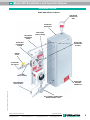
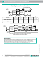
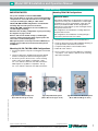
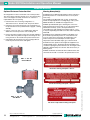
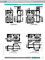
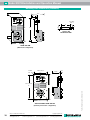
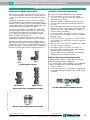
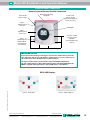
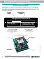
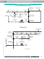
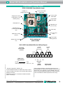
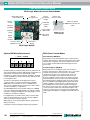
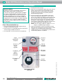
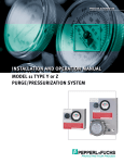
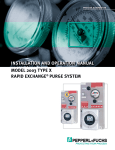
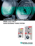
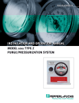
PROCESS AUTOMATION
INSTALLATION AND OPERATION MANUAL
MODEL 2001B TYPE X
PRESSURIZATION SYSTEM
Model 2001B Installation and Operation Manual
Table of Contents
Page 23 Operating Sequence
Class II pressurization operation
Page 2 System Purpose and Description
Purpose, System description, Important notes
Page 3 Identifying Your System
Defines specific features of the system
Page 3 General Information
System & material specifications, Spare parts, Tools
& test equipment, System accessories
Page 4 Enclosure and Device Design
Design requirements, Adjacent enclosures, Device
ventilation, Temperature limitations
Page 5 Installation Overview
Installation diagram
Page 6 Getting Started
Establishing connection sizes, Determining enclosure
inlet & outlet connection locations
Page 7 System Mounting
LH, RH, TM, BM & WM configurations, FM & PM
configurations
Page 11 Pneumatic Tubing Requirements
Protective gas supply requirements, Pneumatic
connection requirements
Page 12 Tubing Connection Points
LH, RH, TM, BM, WM, FM, & PM configurations
Page 13 Tubing Installation
LH, RH, TM, BM, WM, FM & PM tubing
configurations
Page 14 Electrical Supply Requirements
General wiring requirements, EPCU power & alarm
signal, Enclosure wiring methods & connections
Page 15 Electrical Power Control Unit
General layout & conduit connection points
Page 16 EPCU Power Rating
Power rating nameplate, Assembled electronics
Page 17 Electrical & Pneumatic Diagrams
LH, RH, TM, BM, WM, FM, & PM configurations
Page 18 Conduit Installation
EPCU electrical conduit, Optional intrinsic safety
Barrier conduit and EPCU conduit connection parts
Page 19 Power Modules & Wiring Diagram
EPCU 120/220 VAC & 24-48 VDC power modules
Page 20 Logic Module & Barrier Wiring
Optional ISB wiring requirements & diagram, EPCU
power control modes
Page 21 Barriers & Field Adjustments
ISB description & factory programming, LED display
indicators, Timer functions & settings
Subject to modifications without notice
Pepperl+Fuchs Group
USA: +1 330 486 0002
www.pepperl-fuchs.com
[email protected]
Page 26 System Maintenance
Page 27 Systems Identification & Application Information
Purpose and Description
Purpose
Pepperl+Fuchs' Bebco EPS System allows the use of generalpurpose or nonrated electrical or electronic devices, with
exception to devices that produce excessive heat, utilize
combustible gas, or expose arcing contacts to the hazardous
atmosphere, in NEMA (National Electrical Manufacturers
Association) 4 or 12 enclosures in the place of explosion proof
NEMA 7 enclosures. Other purposes include heat, moisture and
dust contamination prevention.
Model 2001B is an enclosure pressurization system that
operates on a supply of compressed instrument air or inert gas. It regulates and monitors pressure within sealed (protected)
enclosures, to prevent combustible dust accumulation within
the enclosure(s). Intended exclusively for Class II areas, the
system is designed to maintain a “safe” (1.0") pressure on
one or more enclosures not exceeding a total volume of fifty
cubic feet. In addition, the system includes an electrical
power control unit (EPCU) that monitors system operation
and controls enclosure power. These processes reduce the
hazardous (classified) area rating within the enclosure(s), in
accordance with the NEC - NFPA 70, Article 500, NFPA 496
and ISA12.4
Important Notes
One (1) permanent file copy and one (1) operations copy of
this manual must be studied and retained by the operator of
this system. User’s agents are responsible for transferring this
manual to the user, prior to start-up.
The contents of this manual have been arranged to allow the
use of this product as a stand-alone device on equipment
and enclosures supplied by the user or its agents. The
manual’s parameters encompass a combination of both
National Fire Protection Association (NFPA) requirements and
Pepperl+Fuchs, Inc. requirements. Pepperl+Fuchs therefore
acknowledges the use of NFPA 496 as a guideline, that we
have enhanced certain NFPA requirements and that additional
information has been compiled to complete this document. The manual is intended as a complete guide and must be
considered, unless specifically stated otherwise, that all
directives contained herein are requirements for safe, practical
and efficient use of this product.
This system is not intended for use to protect enclosures
or devices that contain ignitable concentrations of gases or
vapors. This exclusion generally applies to process or product
analyzing systems equipment.
All specifications are subject to change without notice.
Germany: +49 621 776 2222
[email protected]
Copyright Pepperl+Fuchs
Singapore: +65 6779 9091
[email protected]
Part No. 512246 Drawing No. 129-0209a 03/09
Page 9 Mounting Plate Dimensions
Mounting plate dimension diagrams
2
Page 25 Warranty and Liability Statements
Warranty notes, General terms, Limitations
Description
Page 8 Hardware Mounting
Optional enclosure protection vent, Warning
nameplates
Page 22 Set-Up Procedure
Pressurization set-up
Page 24 Troubleshooting Procedures
Model 2001B Installation and Operation Manual
SCALE = 1X
All dimensions are in inches.Identifying Your System
All outside corners R=0.13
This enclosure
protection system is offered in various styles.
olerances: 2-place
dec. +/- .01
LABEL P/N: 510955
In order to comply with the NFPA 496 standard requiring
protection against over pressurization of the protected
enclosure, the installer must install one of the following items
in addition to the enclosure protection system.
Model 2001B-STD-CII Type X
a) Install an EPV-3 enclosure protection vent on the protected
enclosure.
For proper installation and operation, examine the system
model number nameplate to identify the system style, area
classification, and type, as noted below.
eX
LA
S SI FIE
D
C
50 CUBIC FEET MAXIMUM ENCLOSURE VOLUME
CLASS II, DIVISION 1, GROUPS E, F & G TO NONHAZARDOUS
b) Install a tamper-proof regulator upstream of the enclosure
protection system's system supply inlet to pre-regulate
protective gas supply to 5 psi max.
T3C
®
**Enclosure integrity determines actual flow rate
RWRITERS
SOCIATION
QUIPMENT
PURGE CONTROL FOR USE IN HAZARDOUS LOCATIONS. CLASSIFIED BY UNDERWRITERS
LABORATORIES INC. ® IN ACCORDANCE WITH THE NATIONAL FIRE PROTECTION ASSOCIATION
STANDARD FOR PURGED AND PRESSURIZED ENCLOSURES FOR ELECTRICAL EQUIPMENT
NFPA 496-1996
4S11
CONTROL
RNAL AREA
MCL 2001A.
APPROVED BY FM APPROVALS AS ASSOCIATED TYPE X PRESSURIZATION CONTROL
EQUIPMENT FOR USE IN HAZARDOUS LOCATIONS. REDUCES THE INTERNAL AREA
OF A CONNECTED ENCLOSURE IN ACCORDANCE WITH DRAWING NUMBER MCL 2001B.
2001B - STD - CII - NR - LH - ##
LABEL P/N: 510957
Series Model Number
System
Style
del 2001C-STD-CII
Type
X
STD - Standard
Area Classification
S SI FIE
LA
CII
T3C - Class II, Group E, F & G Area
Power Control Mode
NR
- Normal Running
NTROL FOR USE IN HAZARDOUS LOCATIONS. CLASSIFIED
BY UNDERWRITERS
RIES INC. ® IN ACCORDANCE WITH THE NATIONAL FIRE PROTECTION
CB -ASSOCIATION
Conditional Bypass
FOR PURGED AND PRESSURIZED ENCLOSURES FOR ELECTRICAL EQUIPMENT
NFPA 496-1996
Mounting Configuration
4S11
LH - left hand
left side of enclosure
BY FM APPROVALS AS ASSOCIATED TYPE X PRESSURIZATION CONTROL
- right
right side of enclosure
T FOR USE IN HAZARDOUS LOCATIONS. REDUCESRH
THE INTERNAL
AREAhand
NECTED ENCLOSURE IN ACCORDANCE WITH DRAWING
NUMBER- MCL
TM
top2001C.
mount
top of enclosure
BM - bottom mount
bottom of enclosure
WM - wall mount
wall surface
FM* - frame mount
external frame or rack
PM* - panel mount enclosure surface cutout
D
C
250 CUBIC FEET MAXIMUM ENCLOSURE VOLUME
CLASS II, DIVISION 1, GROUPS E, F & G TO NONHAZARDOUS
®
Reference part number above for current spare parts pricing.
Immediate pricing is available to all confirmed customers.
Installation Tools & Testing Equipment
System dimensions:
See pages 9 & 10
Shipping weight ( lbs.):
38
temp.
-20 °F to +120 °F
ngaben. Es darf nichtOperating
ohne Absprache
mitrange:
dem Normenfachmann geändert werden!
Supply pressure range:
* 5 -120 psi max.
ormation. It must not be altered without the authorization of the norm expert!
When using the optional inline filter, max. supply pressure is 80 psi
Supply requirements:
change notice.
respons.
setpoint:
approved
Safe pressure flowrate:
150-0691
norm
System supply port:
Enclosure supply fitting:
Enclosure reference fitting:
EPCU conduit port size:
EPCU power requirements:
(European 240 voltage only)
EPCU power consumption:
Power relay contacts:
Alarm relay N.O. contact:
Alarm relay N.C. contact:
001[A or B or C]-STD-CII
X
Safe Type
pressure
Part No. 512246 Drawing No. 129-0209a 03/09
Zinc w/ enamel finish
Polycarbonate
Aluminum w/ enamel finish
316 SS forged body
316 SS 1/4" .035 welded
Silkscreened Lexan® & SS
Stainless steelscrews & bolts
316 14 ga #3 brush SS
Bead blast cast alum.
Silkscreened SS
Qty Description
Part # (supercedes)
1 Enclosure pressure indicator 513235 (001027)
1 Enclosure pressure control regulator 513236 (002050)
1 Safe pressure switch
510357 (005205)
1 Series 2000 logic module-Ver. 2.0
510279 (005000)
1 Series 2000 VAC power module
510304 (005020)
1 Series 2000 VDC power module
510305 (005021)
1 Installation & operation manual
129-0209
1 Enclosure warning nameplate-CII
513009 (EWN-2)
D
KGROUND
G TO PRINT FONTS,
General Information
MES ARE CONTAINED IN
AME UNDER DRAWING
System Specifications
scale: 1:1
Regulator body:
Regulator handle:
Enclosure pressure gauge:
Tube fittings:
Tubing:
System nameplates:
Fastener hardware:
Mounting plate:
EPCU enclosure body:
Enclosure warning nameplate:
Recommended Spare Parts
## - Additional factory installed accessories
s released in EDM or with a valid production documentation!
Material Specifications
Lexan® is a registered trademark of the General Electric Corporation
* FM & PM configurations feature flush mount EPCU.
P SS
P SS
P SS
* With EPV-3 vent - 120 psi max. to 5 psi minimum
Without EPV-3 vent - 5 psi maximum
1/2" chuck drill
Complete set of drill bits
1/2" & 1" conduit knockout punch or 1.375" hole saw
Complete set of tubing, conduit bending, instrument fitting and
craftsman hand tools
date: 2002-Dec-15electrical
Clean air or inert gas
1.0" @ safe
pressure
0 - 250 scfh flowmeter (connected upstream of protection
125-0786B
US.SSJ ** 0.1-3.5 SCFH
system to determine air consumption and flow during set-up)
sheet
of 1
US.AAS 3/8"
tube 1fitting
3/8" tube fitting
1/4" tube fitting
1/2"
Released
EDMFPT
checkout 2008-JUL-17
120 VAC 60 Hz 1Ø
240 VAC 50 Hz 1Ø
500 mA
20 Amps @ 240 VAC
20 Amps @ 28 VDC
20 Amps @ 48 VDC
20 Amps @ 240 VAC
20 Amps @ 28 VDC
15 Amps @ 240 VAC
10 Amps @ 28 VDC
US.JMB
Subject to modifications without notice
Pepperl+Fuchs Group
USA: +1 330 486 0002
www.pepperl-fuchs.com
[email protected]
Germany: +49 621 776 2222
[email protected]
Copyright Pepperl+Fuchs
Singapore: +65 6779 9091
[email protected]
3
Model 2001B Installation and Operation Manual
Model 2001B System Accessories
Adjacent Enclosures
Optional Enclosure Protection Vents
EPV-3-SA-00
Straight w/ spark arrestor
EPV-3-SA-90
Rt angle w/ spark arrestor
1. Adjacent enclosures must be protected by one of the
following means:
System mounting kit
Div. 1 remote alarm horn
Div. 1 remote alarm beacon
Div. 2 remote alarm beacon
L fitting conduit kit
T fitting conduit kit
Tamperproof regulator w/ gauge
Switch resistor module
P+F NAMUR sensor
1/4" flush connector
3/8" flush connector
3/8" bulkhead connector
1" pipe connector
Channel A barrier
Channel B barrier
Channel C barrier
Redundant safe pressure switch
Power switch key lock assembly
Enclosure & Device Design
Enclosure Design Requirements
1. All windows must be shatterproof and sized as small as
possible.
2. All NFPA 496 required markings must be placed on or near
all enclosure doors and covers.
3. The enclosure must withstand an internal pressure of five (5)
inches of water without sustaining permanent deformation
and resist all corrosive elements in the surrounding
atmosphere.
4. All lightweight objects in the enclosure, such as paper or
insulation, must be firmly secured.
5. The enclosure should be constructed from materials such as
metal or nonstatic polycarbonate to meet or exceed NEMA
4 or 12 performance requirements, but does not require
third party approval.
6. The installation of obstructions or other barriers that block
or impede the flow of protective gas must be avoided.
7. The creation of air pockets or other areas that trap
flammable gases within the enclosure or devices must be
avoided.
8. The enclosure should be located in an area where impact
hazards are minimal.
9. If the enclosure is nonmetallic and contains equipment that
utilizes or switches power loads greater than 2500 VA, it
must be constructed from substantially noncombustible
materials, such as materials designed to meet or exceed
ANSI/UL94 ratings of 94 V-0 or 94 5V.
4
Subject to modifications without notice
Pepperl+Fuchs Group
USA: +1 330 486 0002
www.pepperl-fuchs.com
[email protected]
a) purged or pressurized in series with the protected
enclosure
b) purged or pressurized separately
c) protected by other means; e.g., explosion proof
enclosures, hermetically sealed devices or intrinsic safe
circuits
2. Adjacent purged or pressurized enclosures must be
designed to meet all construction requirements above.
Total Volume Calculation
1. The total volume of all pressurized enclosures, devices and
wireways must be considered.
2. All enclosure, device, and wireway volumes must be
calculated without consideration of internally consumed
space.
Device Ventilation
1. Enclosed devices within the protected enclosure which do
not exceed 1.22 in3 of free volume do not require ventilation
to the protected enclosure.
2. If the free volume of an internal device exceeds 1.22 in3 it
must be protected by one of the following means:
a) ventilated on the top and bottom sides with 1 in2 of
opening for each 400 in3 of volume within the internal
protected enclosure, at a minimum diameter of 1/4"
b) purged in series with the protected enclosure or be
purged separately or
c) protected by other means; e.g., explosion proof
enclosures, hermetically sealed devices, or intrinsic safe
circuits.
Temperature Limitations
1. The enclosure must have no surface area that exceeds 80
percent of the flammable or ignitable substance’s autoignition temperature.
2. Internal devices that exceed this temperature must be
protected by one of the following manners:
a) The device is enclosed in a chamber that is CULUS or
FM listed as a hermetically sealed device that prohibits
the entrance of a flammable or ignitable substance, and
maintains a surface temperature below temperature
limits.
b) It can be proven by testing that the devices will not ignite
the substance involved.
c) The device is purged in a separate enclosure that bears
an ETW (enclosure temperature warning nameplate).
Devices may be accessed only after power has been
removed and the device has been allowed to cool to
safe temperature, or the area is positively known to be
nonhazardous.
Germany: +49 621 776 2222
[email protected]
Copyright Pepperl+Fuchs
Singapore: +65 6779 9091
[email protected]
Part No. 512246 Drawing No. 129-0209a 03/09
Additional Items
SMK -2, -3 or -10
RAH
RAB-1
RAB-2
LCK
TCK
TR-10G
SRM-4000
NJ...
EFC-4
EFC-6
EBC-6
EPC-13
IS1
IS2
IS3
RP1
L Model 2001B Installation and Operation Manual
Installation Overview
Model 2002-STD-CI-LH Shown
ENCLOSURE
PROTECTION
VENT
PROTECTED
ENCLOSURE
ENCLOSURE
SUPPLY TUBING
ENCLOSURE
REFERENCE
TUBING
ENCLOSURE
CONNECTION
FITTINGS
ENCLOSURE
PROTECTION
SYSTEM
SERVICE
VALVE
PROTECTIVE
GAS SUPPLY
SYSTEM
SUPPLY TUBING
ENCLOSURE
WARNING
NAMEPLATE
Part No. 512246 Drawing No. 129-0209a 03/09
EPCU BREATHER
DRAIN FITTING
EPCU POWER & ALARM SIGNAL
WIRING CONDUIT & SEAL
Subject to modifications without notice
Pepperl+Fuchs Group
USA: +1 330 486 0002
www.pepperl-fuchs.com
[email protected]
Germany: +49 621 776 2222
[email protected]
Copyright Pepperl+Fuchs
Singapore: +65 6779 9091
[email protected]
5
Model 2001B Installation and Operation Manual
Getting Started
Typical Single Protected Enclosure Connections
ENCLOSURE PROTECTION VENT
(Optional)
1/2"
PROTECTIVE
GAS SUPPLY
HEADER
C
REFERENCE
ENCLOSURE
PROTECTION
SYSTEM
A
Description
*Tubing or pipe diameter
Maximum tubing / pipe length and
maximum number of bends / elbows
PROTECTED
ENCLOSURE
SUPPLY
E
B
A
B
C
System
supply tubing
Enclosure
supply
Enclosure
reference
3/8" O.D. tubing 3/8" O.D. tubing
fully reamed
fully reamed
20 feet
10 bends
D
E
Multi - enclosure Optional remote
venting
connections
1/4" O.D. tubing
fully reamed
1" I.D. pipe fully reamed
1" I.D. pipe fully reamed
20 feet
10 bends
10 feet
5 elbows
30 feet
5 elbows
5 feet
5 bends
TYPICAL MULTIPLE PROTECTED ENCLOSURE CONNECTIONS
B
1/2"
PROTECTIVE
GAS SUPPLY
HEADER
ENCLOSURE
PROTECTION
SYSTEM
SUPPLY
D
PROTECTED
ENCLOSURE
D
PROTECTED
ENCLOSURE
PROTECTED
ENCLOSURE
REFERENCE
C
A
*NOTE: Tube and pipe sizes are trade sizes and are not equal in inside diameter.
DO NOT substitute tube for pipe with same trade size.
HELPFUL HINTS
To ensure adequate protective gas flow to the protected enclosure(s), all piping and tubing must be fully reamed.
Precautions must be taken to prevent crimping and other damage to protective gas piping and tubing.
Part No. 512246 Drawing No. 129-0209a 03/09
When protecting multiple enclosures with a single enclosure protection system, the enclosures must be
connected in series from the smallest to the largest to ensure adequate protective gas flow.
6
Subject to modifications without notice
Pepperl+Fuchs Group
USA: +1 330 486 0002
www.pepperl-fuchs.com
[email protected]
Germany: +49 621 776 2222
[email protected]
Copyright Pepperl+Fuchs
Singapore: +65 6779 9091
[email protected]
Model 2001B Installation and Operation Manual
System Mounting
IMPORTANT NOTES
Mounting FM & PM Configurations
The system should be mounted at EYE LEVEL.
Care must be taken to ensure the system and all protruding
components are clear of all enclosure accesses (doors and
covers) and conduit, pipe, tubing or cable entries.
LH, RH, TM, BM and WM configurations are intended for
mounting adjacent to the protected enclosure.
LH, RH, TM & BM configurations are also suitable for 2"
schedule 40 pipe mounting.
Determine the mounting configuration of your system using
the diagrams on pages 9 & 10.
Remove and save the manila envelope (containing the
enclosure warning nameplate) which may be taped to the
outer surface of the mounting flange.
Although all systems are factory tested and calibrated, we
strongly suggest a bench test of basic functions prior to
installation.
Mounting LH, RH, TM, BM & WM Configurations
1 . Transfer hole pattern of System mounting plate to intended
surface.
2. Check for obstructions hindering bolt fastening, drill and
ream the mounting holes before mounting the system.
HELPFUL HINTS
FM and PM configurations are designed to mount through
a panel cutout one (1) inch smaller than the overall height
and width of the system mounting plate, using clips and
fasteners provided with SMK -10. This design feature
eliminates the need to drill the system mounting bolt holes
in the protected enclosure.
FM configurations are intended for mounting adjacent to
the protected enclosure.
PM configurations are intended for mounting through a
cutout in the protected enclosure surface.
1. Transfer panel cutout pattern to the intended surface.
2. Check for obstructions that could prohibit bolt fastening or
system pneumatic and electrical connections.
3. Cut panel cutout pattern on the intended surface.
4. Deburr all cutout surfaces.
5. Secure system to enclosure using SMK-10, or equivalent
- ten (10) 1/4" x 3/4" stainless steel nuts, bolts, mounting
clips and lock washers.
3. Secure the system to the enclosure, or other mounting
surface, using one (1) SMK-3 or equivalent - six (6) 3/8" x 3/4" stainless steel bolts, nuts and lock washers.
*WM requires one (1) SMK-2 or equivalent - four (4) 3/8" x 3/4" stainless steel bolts, nuts and lock washers.
Typical Surface Mounted System
Typical Pipe Mounted System
(Model 1002-LPS-LH Type Z shown)
Typical Panel/Frame Mounted System
(Model 1002-LPS-PM Type Z shown)
Part No. 512246 Drawing No. 129-0209a 03/09
(Model 1002-LPS-LH Type Z shown)
Subject to modifications without notice
Pepperl+Fuchs Group
USA: +1 330 486 0002
www.pepperl-fuchs.com
[email protected]
Germany: +49 621 776 2222
[email protected]
Copyright Pepperl+Fuchs
Singapore: +65 6779 9091
[email protected]
7
Model 2001B Installation and Operation Manual
Hardware Mounting
Optional Enclosure Protection Vent
Warning Nameplate(s)
All configurations must be mounted in a true vertical position.
An EWN (Enclosure Warning Nameplate) must be located in a
prominent position on or near all enclosure accesses (doors
and covers).
The vent must be located to provide access for routine testing
of the vent’s flapper assembly. A minimum 8" clearance is
required below the vent opening.
1. Determine the vent’s mounting configuration, i.e., -00 vertical mount or -90 side mount. See photos below.
2. Determine vent location and layout vent mounting hole on
the protected enclosure (as determined on page 6, “Getting
Started”).
3. Using a 1.375" hole saw or 1" conduit punch, drill and
deburr the enclosure protection vent mounting hole.
4. Remove the hub mounting nut from the vent hub and place
the hub, with O-ring intact, through the mounting hole. The
O-ring must be on the outside of the protected enclosure.
5. Reinstall the hub mounting nut to the mounting hub from
inside the protected enclosure and tighten.
One (1) EWN is provided with each system, located in the
manila envelope taped to the mounting flange of the system.
Additional EWNs are available from Pepperl+Fuchs.
All EWNs provide labeled spaces allowing the customer to
mark the protected enclosure with: 1) a T Code (temperature
identification number), 2) Class, Group and Division of
surrounding area, and 3) NFPA pressurization Type X, Y or Z,
as may be required by plant and local codes and is required by
NFPA 496.
An ETW (Enclosure Temperature Warning nameplate) must
be located in a prominent position on or near all enclosure
accesses (doors and covers) when the temperature of an
internal component exceeds 80 percent of the ignition
temperature of the flammable vapor, gas or dust involved.
An ETW warns the operator to deenergize all equipment for a
specified length of time, allowing the protected equipment to
cool before opening the protected enclosure. The length of time
required is determined by the customer and can be factory or
field engraved.
All EWNs and ETWs are furnished with an adhesive back, but
should also be riveted or screwed to the protected enclosure.
EPV - 3 - SA - 00
Vertical Mount
Enclosure warning nameplate - Class I
EPV - 3 - SA - 90
Side Mount
Enclosure temperature warning nameplate
8
Subject to modifications without notice
Pepperl+Fuchs Group
USA: +1 330 486 0002
www.pepperl-fuchs.com
[email protected]
Germany: +49 621 776 2222
[email protected]
Copyright Pepperl+Fuchs
Singapore: +65 6779 9091
[email protected]
Part No. 512246 Drawing No. 129-0209a 03/09
Enclosure warning nameplate - Class II
Model 2001B Installation and Operation Manual
Mounting Plate Dimensions
.375" O.D.
TYP. 6
10.75"
4.25"
3.375"
.625"
10.75"
4.25"
3.375"
.625"
.6875"
.6875"
10"
9.5"
20"
20"
18"
19.312"
11"
11"
2001B-STD-LH
(Left hand configuration)
2001B-STD-RH
(Right hand configuration)
10.5"
10.5"
20.75"
20.75"
.6875"
3.5625"
10.75"
20.0625"
11.25"
.375" O.D.
TYP. 6
4.25"
4.25"
3.5625"
.6875"
Part No. 512246 Drawing No. 129-0209a 03/09
.375" O.D.
TYP. 6
10.75"
10.375"
19.25"
.375" O.D.
TYP. 6
2001B-STD-BM
(Bottom mount configuration)
2001B-STD-TM
(Top mount configuration)
Subject to modifications without notice
Pepperl+Fuchs Group
USA: +1 330 486 0002
www.pepperl-fuchs.com
[email protected]
Germany: +49 621 776 2222
[email protected]
Copyright Pepperl+Fuchs
Singapore: +65 6779 9091
[email protected]
9
Model 2001B Installation and Operation Manual
Mounting Plate Dimensions (continued)
12.5"
6"
.375" O.D.
TYP. 4
9"
20"
1"
2"
18"
TYPICAL -WM
MOUNTING FLANGE
11"
2001B-STD-WM
(Wall mount configuration)
1.25"
Panel Cutout
12"
.25" O.D.
TYP. 10
Panel Cutout
21"
10.25"
13"
2001B-STD-FM & 2001B-STD-PM
(Frame & panel mount configuration)
10
Subject to modifications without notice
Pepperl+Fuchs Group
USA: +1 330 486 0002
www.pepperl-fuchs.com
[email protected]
Germany: +49 621 776 2222
[email protected]
Copyright Pepperl+Fuchs
Singapore: +65 6779 9091
[email protected]
Part No. 512246 Drawing No. 129-0209a 03/09
22"
Model 2001B Installation and Operation Manual
Pneumatic Tubing Requirements
Protective Gas Supply Requirements
Pneumatic Connection Requirements
The protective gas supply to the protection system must be a
clean, instrument quality compressed air or nitrogen and must
contain no more than trace amounts of flammable gas, vapor
or dust.
ALL FITTINGS MAY BE CUSTOMER OR FACTORY FURNISHED
The protective gas supply compressor intake must originate
in a nonhazardous location. Suction duct passing through a
hazardous location and the protection system tubing and piping
must be fabricated from noncombustible materials suitable for
prevailing hazards and environmental conditions.
The protective gas supply must originate from a dedicated
instrument quality compressed air header (1/2" pipe or larger),
no farther than twenty (20) feet from the protection system.
Local compressors and gas cylinders should not be used
before consulting with Pepperl+Fuchs.
The protective gas supply to the protection system must be
equipped with a tamper-proof regulator set at 5 psi maximum.
Exception: If the protected enclosure(s) is equipped with an
EPV-3 Enclosure Protection Vent, the protective gas supply to
the protection system must not exceed 120 psi maximum, 5 psi
minimum. (See page 3, "System Specifications" for additional
information concerning protective gas supply requirements.)
1. For system supply, one (1) SC-6 3/8" male straight
connector or one (1) NC-6 3/8" male elbow connector or
equivalent fitting per system.
NOTE: Above fitting is required only if protection system
is furnished with an optional in-line filter kit (model ILFK)
accessory.
One (1) similar fitting which will connect the inert gas supply
tubing to the inert gas supply header connection point and
one (1) lot of 3/8" O.D., .035" wall thickness, welded or
seamless stainless steel tubing.
2. For enclosure supply, one (1) EFC-6 3/8" flush connector,
or one (1) EBC-6 3/8" feed-through connector or equivalent
fitting per system.
3. For enclosure reference, one (1) EFC-4 1/4" flush connector,
or one (1) EBC-4 1/4" feed-through connector or equivalent
fitting per system.
4. One (1) lot of 1/4" & 3/8" O.D., .035" wall thickness, welded
or seamless stainless steel tubing.
5. For multiple enclosure connections, two (2) EPC-13 1"
pipe mounting hubs or equivalent and 1" 150# rated pipe
couplings & unions per interconnection.
One (1) lot 150# rating 1/2" galvanized or aluminum pipe
and fittings, fully reamed and unrestricted.
PM Pneumatic Connection Requirements
NC-6
SC-6
SYSTEM SUPPLY FITTINGS
In addition to item numbers 1, 4, and 5 above, the following
fittings are required for all PM configurations.
1. For system supply on PM configurations, one (1) additional
EBC-6 or equivalent 3/8" through bulkhead fitting per
system is required.
2. For atmospheric reference, one (1) PRB-4 or equivalent 1/4"
female bulkhead fitting and stainless steel sintered element
is required.
EFC-4 & EFC-6
EBC-4 & EBC-6
Part No. 512246 Drawing No. 129-0209a 03/09
ENCLOSURE SUPPLY & REFERENCE FITTINGS
PRB-4
SYSTEM ATMOSPHERIC REFERENCE FITTING
EPC-13
MULTIPLE ENCLOSURE CONNECTION FITTING
Subject to modifications without notice
Pepperl+Fuchs Group
USA: +1 330 486 0002
www.pepperl-fuchs.com
[email protected]
Germany: +49 621 776 2222
[email protected]
Copyright Pepperl+Fuchs
Singapore: +65 6779 9091
[email protected]
11
Model 2001B Installation and Operation Manual
Tubing Connection Points
LH, RH, TM, BM, WM & FM Configuration Connection Points
System
supply
inlet
Enclosure
pressure
gauge
Enclosure
reference
inlet
Enclosure
pressure
control
regulator
Flame
arrestor
Enclosure
supply
outlet
Venturi
orifice
Mounting
plate
PM Configuration Connection Points
System
supply
inlet
Enclosure
pressure
gauge
Atmospheric
reference
inlet
Enclosure
pressure
control
regulator
Electrical
power control
unit
Enclosure
supply
outlet
Mounting
plate
HELPFUL HINT
Pneumatic connections are bolded.
12
Subject to modifications without notice
Pepperl+Fuchs Group
USA: +1 330 486 0002
www.pepperl-fuchs.com
[email protected]
Germany: +49 621 776 2222
[email protected]
Copyright Pepperl+Fuchs
Singapore: +65 6779 9091
[email protected]
Part No. 512246 Drawing No. 129-0209a 03/09
Flame
arrestors
Model 2001B Installation and Operation Manual
Tubing Installation
Tubing PM Configurations
HELPFUL HINTS
All work must be performed by technicians qualified in
pneumatic tubing and electrical conduit installation.
Pepperl+Fuchs recommends the use of .035" wall
thickness, welded or seamless stainless steel tubing.
If flexible tubing is used, it must be installed in a manner
that protects it from damage and corrosion.
Tubing LH, RH, TM, BM, WM & FM
Configurations
Enclosure bulkhead fittings
1. Select the fittings required to install the system supply,
system supply bulkhead Fitting and atmospheric reference
bulkhead fitting. See page 11, “Pneumatic Tubing
Requirements.”
2. Choose location for the system supply bulkhead fitting. This
fitting allows the protective gas supply to pass through the
wall of a protected enclosure to the protection system’s
regulator supply inlet connection.
3. Choose location for the atmospheric reference bulkhead
fitting. This fitting allows the enclosure pressure gauge to
reference atmospheric pressure.
System supply connections
1. Select or install a protective gas supply header tap, fitted
with the proper tube size fitting and located within twenty
(20) feet of the enclosure protection system.
4. Drill and deburr system supply and reference bulkhead
fitting holes in the protected enclosure. Mount the fittings.
2. If a service valve is placed between the protective gas
supply header and the enclosure protection system, it must
be installed in close proximity of the protected enclosure
and be labeled in accordance with NFPA 496.
System supply & reference connections
3. Select the appropriate fittings required to connect the
protective gas supply to the protection system regulator as
determined on page 11, “Pneumatic Tubing Requirements”.
2. If a service valve is placed between the protective gas
supply header and the protection system, it must be in
close proximity of the protected enclosure and labeled in
accordance with NFPA 496.
4. Determine appropriate tubing route from the protective gas
supply header to the protection system regulator.
5. Bend tubing using industrial grade benders, check tubing
fit to ensure proper seating between the tubing and fittings.
Fully ream all tubing ends.
1. Select or install a protective gas supply header tap, fitted
with the proper tube size fitting and located within twenty
(20) feet of the enclosure protection system.
3. Determine appropriate tubing route from the protective gas
supply header to the system supply bulkhead fitting.
4. Determine appropriate tubing route from the system supply
bulkhead fitting to the protection system regulator.
6. Install tubing and tighten all fittings to fitting manufacturer’s
specifications. Secure tubing to appropriate structural
supports as required.
5. Determine appropriate tubing route from the atmospheric
reference bulkhead fitting to the enclosure pressure gauge’s
reference inlet connection.
Enclosure supply & reference connections
6. Bend tubing using industrial grade benders, check tubing
fit to ensure proper seating between the tubing and fittings.
Fully ream all tubing ends.
1. Choose location for the enclosure supply connection(s)
based on the requirements on page 6, “Getting Started.”
2. Place the enclosure reference connection fitting directly
behind the enclosure protection system whenever possible.
For systems protecting multiple enclosures in series, the
enclosure reference connection fitting must be placed
on the last enclosure in the series. See page 6, “Getting
Started.”
7. Install tubing and tighten all fittings to fitting manufacturer’s
specifications. Secure tubing as required.
3. Drill and deburr enclosure supply and reference fitting holes
on the protected enclosure. Mount the fittings.
Part No. 512246 Drawing No. 129-0209a 03/09
4. Determine appropriate route for the enclosure supply and
reference tubing.
5. Bend tubing using industrial grade benders, check tubing
fit to ensure proper seating between the tubing and fittings.
Fully ream all tubing ends.
6. Install tubing and tighten all fittings to fitting manufacturer’s
specifications. Secure tubing to appropriate structural
supports as required.
Subject to modifications without notice
Pepperl+Fuchs Group
USA: +1 330 486 0002
www.pepperl-fuchs.com
[email protected]
Germany: +49 621 776 2222
[email protected]
Copyright Pepperl+Fuchs
Singapore: +65 6779 9091
[email protected]
13
Model 2001B Installation and Operation Manual
Electrical Supply Requirements
Typical Enclosure Wiring Methods
WARNING! This device contains electrical parts which
can cause shock or injury.
All electrical connections, conduit and fittings on the protected
enclosure must be suitable for the hazardous location in which
they are installed. In addition, all conduit and wire must be
installed in accordance with NEC as required and all relevant
plant and local codes.
Conduit seals must be utilized on all electrical conduit
connections and poured with an approved compound prior to
operation of the protection system.
Exception: Do not use seals on conduit used as a protected
“wireway” to supply protective gas to adjacent protected
enclosures. The same conduit can be utilized for both electrical
and pneumatic service to an adjacent protected enclosure(s),
provided the conduit is oversized to allow a minimum free
clearance equal to or larger than the pipe size required between
multiple enclosures as stated on page 6, “Getting Started.”
HELPFUL HINT
Pepperl+Fuchs recognizes it may be impractical to pour
all electrical conduit seals prior to installation in the field.
However, all conduit connections must be sealed for
proper testing and operation of the enclosure protection
system. Therefore, Pepperl+Fuchs recommends the use
of temporary seals such as duct seal or masking tape for
bench or shop testing, prior to final field installation.
Protected enclosures must be wired similar to explosion proof
enclosures, in accordance with Article 500 of the National
Electric Code - NFPA 70.
Single conductor wiring must be placed in rigid metal conduit,
seal-flex conduit, or other mediums approved for use in the
hazardous location surrounding the protected enclosure.
Additionally, NFPA 496 requires approved conduit seals on all
pressurized enclosure conduit wiring entries, in accordance
with NFPA 70. Furthermore, the use of an approved conduit
seal is simply the most practical way to prevent excessive
leakage through conduit connections.
However, while explosion-proof enclosures require conduit
seals on all cable entries, in accordance with NFPA 70, other
methods of sealed cable entries that are suitable for hazardous
locations can be used, such as compression glands.
In conclusion, there are two primary goals. First, the installer
should ensure that all associated wiring and cable is protected
by pressurization or other means, such as explosion-proof
conduit or intrinsic safety barriers. Secondly, the installer must
ensure that all associated conduit and wireways are sealed
to conserve protective gas, unless they are used to supply
protective gas to other enclosures or devices.
Typical Enclosure Wiring Connections
Conduit
EPCU Power Requirements
Seal
The electrical power control unit's (EPCU) electrical power
source must originate from a circuit breaker or fused
disconnect suitable for the hazardous location in which it is
installed. The power source should be uninterrupted and the
switch must be located within fifty (50) feet of the protected
enclosure(s) and the enclosure protection system and be
properly marked. For EPCU power specifications see page 3,
"System's Specifications."
Conduit
Seal
Gland
fitting
Cable
Alarm Signal Requirements
Pepperl+Fuchs strongly recommends use of the optional alarm
system contacts of the EPCU, connected to an alarm system
located in a constantly attended location to indicate the failure
of the enclosure protection system. For EPCU alarm signal
specifications see page 3, "System's Specifications."
Conduit
Seal
Pressurized
raceway
Protected enclosure
or device
14
Subject to modifications without notice
Pepperl+Fuchs Group
USA: +1 330 486 0002
www.pepperl-fuchs.com
[email protected]
Germany: +49 621 776 2222
[email protected]
Copyright Pepperl+Fuchs
Singapore: +65 6779 9091
[email protected]
Explosion
proof device
Intrinsically
safe or fiber
optic device
Intrinsically
safe or fiber
optic device
Independently
pressurized
device
Adjacent
pressurized
device
Part No. 512246 Drawing No. 129-0209a 03/09
General Wiring Requirements
Model 2001B Installation and Operation Manual
Electrical Power Control Unit
General Layout & Electrical Conduit Connections
EPCU electrical rating
nameplate
Power mode
selector switch
Power mode
selector switch
(optional mounting hole
-factory use only-)
Type 7
explosion proof
enclosure
LED display
Type 7
explosion proof
screw cover
1/2" NPT conduit
connection ports
typical 6
(see important notes
below)
Type 7
explosion proof
breather drain
(see important
notes below)
IMPORTANT NOTES
For proper moisture drainage of the Type 7 enclosure, the installer must 1) move the
Type 7 breather drain to one of the bottom conduit entrances or 2) use drain seals on
all conduit connected to the bottom two conduit entrances.
The Type 7 breather drain is not provided or required with PM configurations.
Top two conduit entrances will be dedicated for Intrinsic Safe wiring ONLY when the
EPCU is supplied with Pepperl+Fuchs' optional ISB intrinsic safety barriers.
Part No. 512246 Drawing No. 129-0209a 03/09
EPCU LED Displays
Class II - Alarm & Bypass
Class II - Alarm Only
Subject to modifications without notice
Pepperl+Fuchs Group
USA: +1 330 486 0002
www.pepperl-fuchs.com
[email protected]
Germany: +49 621 776 2222
[email protected]
Copyright Pepperl+Fuchs
Singapore: +65 6779 9091
[email protected]
15
Model 2001B Installation and Operation Manual
EPCU Power Rating
EPCU Electrical Power Rating Nameplate
The EPCU (Electrical Power Control Unit) of this Type "X" purging system is offered in various styles. For proper installation and
operation, begin by examining the EPCU electrical rating nameplate to identify the system input voltage and power requirements,
enclosure power and alarm contact ratings and third party approval markings. Next, match the LED display of your EPCU with
one of the displays shown on page 15. The EPCU LED Display will help identify the options featured on your system e.g., normal
running mode or conditional bypass.
REQUIRED WARNING
STATEMENTS
EPCU SERIAL
NUMBER
MODEL 2000 ELECTRICAL POWER CONTROL UNIT
CAUTION: OPEN CIRCUIT BEFORE REMOVING COVER
ATTENTION: OUVRIR LE CIRCUIT AVANT D'ENLEVER LE COUVERCLE
SERIAL NO.
XXXXXX
CSA Encl. 3
CLASS I, DIV. 1, Gr C&D
CLASS II, DIV. 1, Gr E, F, G HAS
UL & FM APPROVALS ONLY
INPUT VOLTAGE & POWER REQUIREMENTS
ENCL POWER & ALARM CONTACTS
ARE RATED 120/240 VAC, 20 AMPS
120 SINGLE PHASE, 60 CYCLE, 1 AMP
240 SINGLE PHASE, 50 CYCLE, 1 AMP
EPCU INPUT POWER
REQUIREMENTS
AREA CLASSIFICATION
Defines the area classifications
for which the EPCU is suitable for
operation
Factory set at time of order
Assembled EPCU Electronics Module
Logic module
120/240 VAC
Power module
16
Subject to modifications without notice
Pepperl+Fuchs Group
USA: +1 330 486 0002
www.pepperl-fuchs.com
[email protected]
Pressure switch
module
Germany: +49 621 776 2222
[email protected]
Copyright Pepperl+Fuchs
Singapore: +65 6779 9091
[email protected]
Part No. 512246 Drawing No. 129-0209a 03/09
Power module
cable
Model 2001B Installation and Operation Manual
Electrical & Pneumatic Diagrams
LH, RH, TM, BM, WM & FM Configurations
Conduit seal
Conduit seal
Electrical power
control unit
Enclosure
reference
tubing
Sintered
vent
Breather
drain
Venturi
orifice
System
supply
Union
Union
Optional enclosure
protection vent
Electrical power
supply conduit
hub
Enclosure reference
bulkhead fitting
Enclosure
pressure gauge
Enclosure
supply
tubing
System supply
tubing
Enclosure supply
bulkhead fitting
Enclosure pressure
control regulator
Protected enclosure
PM Configurations
Optional enclosure
protection vent
Electrical power
supply conduit
hub
Atmospheric pressure
reference bulkhead
fitting
Electrical power
conduit
Atmospheric
reference
tubing
System
supply
Conduit seal
Union
Electrical
power to
enclosure
Electrical power
control unit
Enclosure pressure
control regulator
Part No. 512246 Drawing No. 129-0209a 03/09
Inlet
System
supply
tubing
Conduit seal
Enclosure
pressure
reference
Enclosure
pressure
reference
Enclosure pressure
gauge
System supply
bulkhead fitting
Union
Enclosure
supply
discharge
Protected enclosure
Subject to modifications without notice
Pepperl+Fuchs Group
USA: +1 330 486 0002
www.pepperl-fuchs.com
[email protected]
Germany: +49 621 776 2222
[email protected]
Copyright Pepperl+Fuchs
Singapore: +65 6779 9091
[email protected]
17
Model 2001B Installation and Operation Manual
Conduit Installation
EPCU Electrical Conduit
EPCU Conduit Connection Parts
Unplug the four unlabeled conduit entrances located on the
sides and bottom of the EPCU enclosure (See page 15, "EPCU
Layout" for conduit entrance layout).
The installer must mount the Type 7 drain fitting supplied with
the system (except for PM configurations) in one of the bottom
conduit entrances of the EPCU, or utilize drain seals on all
conduit connected to the bottom two (2) conduit entrances of
the EPCU.
Following the instructions listed below, install all conduit,
fittings and seals (or drain seals if utilized) between the EPCU,
alarm system (if utilized) and the protected enclosure(s). Plug all
remaining EPCU conduit entrances.
1. Choose the location for the enclosure’s electrical conduit
connection(s) based on the requirements on page 14,
“Electrical Supply Requirements”.
Fitting Kits Can Be Factory Furnished
1. To connect enclosure power from the EPCU to the
protected enclosure, one (1) LCK (L fitting Conduit Kit) or
equivalent conduit elbow, coupling and seal fittings.
2. For EPCU to enclosure wiring connection with one (1)
additional conduit connection path, one (1) TCK (T fitting
Conduit Kit) or equivalent conduit tee, coupling and seal
fittings.
IMPORTANT NOTE: Model LCK & TCK are offered primarily
to OEMs attempting to achieve a "field ready" installation.
In all cases, limited pipe fitting skills will be required. Precut 150# galvanized steel pipe nipples can be acquired
from local plumbing shops, but a hole saw or punch and
wrenches are required to install kits.
2. Drill and deburr enclosure conduit fitting holes in the
protected enclosure. Mount the fittings.
3. Determine appropriate route for the enclosure electrical
enclosure and alarm signal conduit.
4. Measure, cut and thread conduit, check conduit fit to insure
proper seating. Fully ream all conduit.
5. Install conduit and tighten all fittings to fitting manufacturers
specifications. Secure conduit to appropriate structural
supports as required.
6. Seal all conduit with an approved compound prior to
operation of the protection system.
Optional Intrinsic Safety Barrier Conduit
Systems supplied with optional Intrinsic Safety Barriers (ISB)
will be supplied with clearly labeled isolated conduit entries,
a solid body wireway with snap cover and plexiglass wiring
partitions. These accessories provide a fully isolated wiring path
to the barrier wiring terminal located on the lower left corner of
the EPCU Logic Module. All IS wiring must be isolated.
1. Choose the location for the enclosure’s IS conduit
connection(s) based on the requirements on page 14,
“Electrical Supply Requirements”.
TCK “T” Fitting
Conduit Kit
2. Drill and deburr enclosure conduit fitting holes in the
protected enclosure. Mount the fittings.
3. Determine appropriate route for the IS conduit.
4. Measure, cut and thread conduit, check conduit fit to ensure
proper seating. Fully ream all conduit.
6. Seal all conduit with an approved compound prior to
operation of the protection system.
LCK “L” Fitting
Conduit Kit
18
Subject to modifications without notice
Pepperl+Fuchs Group
USA: +1 330 486 0002
www.pepperl-fuchs.com
[email protected]
Germany: +49 621 776 2222
[email protected]
Copyright Pepperl+Fuchs
Singapore: +65 6779 9091
[email protected]
Part No. 512246 Drawing No. 129-0209a 03/09
5. Install conduit and tighten all fittings to fitting manufacturers
specifications. Secure conduit to appropriate structural
supports as required.
Model 2001B Installation and Operation Manual
Power Modules & Wiring Diagram
EPCU 120/240 VAC Power Module Layout
Isolated coil
voltage transformer
Power control switch
cable header
Pressure switch
cable header
Voltage input selector
seader (factory set for
120 VAC power)
Logic module
cable header
1 Amp input fuse
Redundant safe
pressure relay
Rapid Exchange
solenoid valve (RESV)
relay
Alarm relay
Enclosure power
relays
RESV factory wiring
terminal
Power module
wiring terminal
EPCU 120/240 VAC
power module
20 Amp enclosure power
fuse
VAC & VDC Power Module Electrical Wiring Diagram
Isolated
Alarm
relay
Isolated
enclosure
power relays
Field wired
power module
terminals
NO
NO
NO
NC
20 AMP
FUSES
1
2
3
EPCU power
supply terminals
Part No. 512246 Drawing No. 129-0209a 03/09
120 VAC
*240 VAC (optional voltage)
Gnd Hot
Gnd Hot
Neu
Neu
* European single phase 240 VAC only.
Power and alarm terminals are feed-thru dry switch contacts.
Caution should be exercised to ensure that the EPCU wiring is
properly connected.
4
5
6
7
In
Out
In
Out
Enclosure
power
supply
terminals
8
9
10
NO Com NC
Remote alarm
relay terminals
Using 12 gauge maximum to 16 gauge minimum wire only,
check EPCU power requirements (see page 14) and wire to the
EPCU power source and alarm system (if utilized). Then route
power source(s) through the EPCU power in and out terminals
to all non-rated devices within the protected enclosure(s).
All terminal connections to the EPCU should be wired with
spade or round lugs.
Subject to modifications without notice
Pepperl+Fuchs Group
USA: +1 330 486 0002
www.pepperl-fuchs.com
[email protected]
Germany: +49 621 776 2222
[email protected]
Copyright Pepperl+Fuchs
Singapore: +65 6779 9091
[email protected]
19
Model 2001B Installation and Operation Manual
Logic Module & Barrier Wiring
EPCU Logic Module & Pressure Switch Module
Barrier fault & active
status indicators
Primary
microprocessor
Barrier C
socket
Factory
programing
header
Primary safe
pressure switch
Space for optional
redundant safe pressure
switch
Redundant
controller
(GAL)
Barrier B
(installed)
Power module
cable header
Barrier A
socket
EDT, SLT &
RET timers
Barrier
wiring
terminal
Pressure switch
calibration access
EPCU pressure
switch module
LED status
display
EPCU Logic Module
Optional ISB Wiring Requirements
EPCU Power Control Modes
Normal Running (NR) Mode
( - ) BLUE ( + ) BROWN
EPCU features an on-off pushbutton power control switch to
activate control functions. Switch must be depressed to initiate
start-up. After completion of start-up, safe pressure must be
lost or switch must be depressed to deenergize enclosure
power relays.
INTRINSICALLY SAFE AUXILIARY INPUTS
-
+
-
C
+
-
+
Conditional Bypass (CB) Mode
All optional intrinsic safety (IS) wiring must be isolated from all
other electrical wiring using the dedicated IS conduit entrances
and wireway of the EPCU. See "Optional ISB Conduit
Installation" on page 18 for more details. In addition, all wiring
must be installed in accordance with the NEC and all relevant
local and plant codes.
The intrinsic safety barriers are designed to function in
conjunction with a customer furnished switch and SRM4000 switch resistor module, or an NJ... NAMUR sensor.
The customer supplied switch must have dry contacts which
contain no inductance or capacitance.
The SRM-4000 switch resistor module and the NJ...NAMUR
sensor are supplied with approximately ten (10) feet of wiring.
Using 16 to 18 gauge shielded wire, the cable lengths can be
extended to a maximum of 100 feet.
EPCU features an on-off-bypass power control switch to
activate control functions. Switch must be set to "on" position
to initiate start-up. After enclosure power is energized,
safe pressure must be lost or switch must be set to "off"
position to deenergize enclosure power. After enclosure
power is energized, switch may be set to "bypass" position,
to temporarily latch enclosure power relays. A flashing LED
then indicates bypass engaged, and the enclosure can then
be accessed without deenergizing power (performed under
specific conditions). Following access, safe pressure must
be reestablished to resume normal operation. At that time,
the switch may be reset to the on position, without disruption
of enclosure power. Alarm relay normally deenergizes only
upon loss of safe pressure, but can be factory programmed
to deenergize when bypass is engaged, if specified at time of
order.
In all applications, the module of the switch resistor module
cable must be installed as close to the customer supplied
switch as possible for proper operation.
Wiring lugs are not recommended for intrinsic safety barrier
wiring connections.
See page 21 for barrier operation and factory programing.
20
Subject to modifications without notice
Pepperl+Fuchs Group
USA: +1 330 486 0002
www.pepperl-fuchs.com
[email protected]
Germany: +49 621 776 2222
[email protected]
Copyright Pepperl+Fuchs
Singapore: +65 6779 9091
[email protected]
Part No. 512246 Drawing No. 129-0209a 03/09
B
A
Model 2001B Installation and Operation Manual
Barriers & Field Adjustments
Optional Intrinsic Safety Barriers Description
Field Adjustable Timer Functions
The EPCU Logic Module can accommodate up to three
intrinsic safety barriers, to interact with remote devices and
affect operation of the EPCU. The barriers are installed and
programmed by the factory at time of order, and they are
designed to function either in conjunction with a customer
furnished switch and a Pepperl+Fuchs furnished resistor
network cable, or a Pepperl+Fuchs furnished proximity
detector. Each barrier develops a low power signal, to create a
two wire closed loop circuit. Operational status of each barrier
is indicated by a green LED to show active (closed switch)
status, and by a red LED to show faulted (line breakage) cable
status. All barriers can be reprogrammed to duplicate other
barrier functions as required, upon specific request.
EDT (Exchange Delay Timer) (FA style only) provides a
time delay to prevent Rapid Exchange solenoid valve from
energizing until safe pressure can be stabilized.
Optional ISB Factory Programing
Barrier A Function - when switch opens
Disables start-up cycle
Deenergizes enclosure power and alarm relay
Functions parallel to safe pressure switch
SLT (Solenoid Latching Timer) (FA style only) provides a time
delay to keep the Rapid Exchange solenoid valve energized
until Rapid Exchange pressure is detected. If the pressure is not
detected, the EPCU will reset.
RET (Rapid Exchange Timer) provides a time delay after Rapid
Exchange pressure is detected, to allow four volume exchanges
(ten volumes for motors) prior to energizing the enclosure
power relays. In Class I areas only, if Rapid Exchange pressure
is lost or interrupted during time delay cycle, the EPCU will
reset.
EDT, SLT & RET Timer Settings
Rotary switch
body
Barrier B Function - when switch opens
Not programmed for this model - custom applications only
E
1
2
D
3
4
B
5
A
6
9
LED Display Indicators
Enclosure power relays deenergized
Enclosure power relays energized
Enclosure pressure > 0.50" w.c.
Enclosure pressure < 0.50" w.c.
Control bypass active - CB mode
0
C
Barrier C Function - when switch closes
Energizes RESV Relay - custom applications only
Power off:
Power on:
Safe pressure:
Alarm active:
Bypass engaged:
F
7
EDT & SLT Timer
POSITION TIME IN SECONDS
8
0
1
2
3
4
5
6
7
8
9
A
B
C
D
E
F
5
10
15
20
25
30
35
40
45
50
55
60
65
70
75
80
RET Timer
POSITION TIME IN MINUTES
0
1
2
3
4
5
6
7
8
9
A
B
C
D
E
F
5
10
15
20
25
30
35
40
45
50
55
60
65
70
75
80
Part No. 512246 Drawing No. 129-0209a 03/09
NOTE: Power must be removed from the EPCU via the local
disconnect switch for approximately 10 seconds for timer
adjustments to reset.
EDT, SLT & RET timers are not functional on Model
2001B.
Subject to modifications without notice
Pepperl+Fuchs Group
USA: +1 330 486 0002
www.pepperl-fuchs.com
[email protected]
Germany: +49 621 776 2222
[email protected]
Copyright Pepperl+Fuchs
Singapore: +65 6779 9091
[email protected]
21
Model 2001B Installation and Operation Manual
Set-up Procedure
4. Seal all protected enclosure(s).
HELPFUL HINTS
Regulator may be in the locked position upon arrival. To
adjust regulator, pull handle to outward position.
To test the vent’s operation, gently prod the vent flapper
open with a soft-pointed object, ( example: eraser end
of a pencil) ensuring that the vent valve works freely. On
vertically configured vents, this can be accomplished
from within the protected enclosure. Side mounted -90
configured vents can be tested by removing the pipe plug
at the bottom of the mounting tee. Multiple operations
require only one test per day if enclosure is not opened or
left unattended.
5. Depress the On-Off pushbutton (NR mode) or turn selector
switch to the On position (CB mode). All LEDs should
illuminate fully for two seconds (self test), then all LEDs
should turn off except Power Off (solid red) and Alarm
Activated (flashing red) LEDs.
6. Turn enclosure pressure control regulator slowly CW to
set the enclosure pressure indicator to a "safe" 1.0 inch
pressure. The safe pressure and timer running LEDs should
be on, the alarm active LED should turn off. Check for a
0.50 to 0.55 inch trip point by slowly stroking the indicator
from 0.40 to 1.0 inch readings. The safe pressure, alarm
active and timer running LEDs should turn on and off when
the indicator reads between 0.50 and 0.55 inches.
Class II Pressurization Set-up
1. Close the enclosure pressure control regulator fully, by turning it counterclockwise (CCW).
2. Remove all traces of combustible dust from the protected
enclosure using a suitable vacuum tool.
3. Check operation of enclosure pressure vent (if utilized).
NOTE: If pressure setting is difficult to stabilize or set, see
page 24, “Troubleshooting Procedures.”
7. Having ensured that the safe pressureand timer running
LEDs are functioning properly, start-up procedures located
on page 23 may now be followed to step through a
complete start up cycle, ensuring that the system functions
normally during all phases of operation.
Model
identification
nameplate
Enclosure
pressure
gauge
Enclosure
pressure
control
regulator
Start-up
instruction
nameplate
LED status
nameplate
Conditional
bypass
operating
instructions
EXP EPCU
enclosure
EPCU power
selector
switch
Part No. 512246 Drawing No. 129-0209a 03/09
System
LED display
Model 2001B-STD-LH
Front View
22
Subject to modifications without notice
Pepperl+Fuchs Group
USA: +1 330 486 0002
www.pepperl-fuchs.com
[email protected]
Germany: +49 621 776 2222
[email protected]
Copyright Pepperl+Fuchs
Singapore: +65 6779 9091
[email protected]
Model 2001B Installation and Operation Manual
Operating Sequence
WARNING! Do not exceed a “safe” pressure with the
enclosure pressure control regulator.
Operators must follow step-by-step sequence of the startup instructions nameplate on the protection system.
Do not use the bypass modes without first securing a "hot
work" permit.
Never leave the system unattended in bypass modes.
Pressurization Operation
With the inert gas supply on, RET Timer set properly, EPCU
power and alarm system energized (if utilized).
1. Carefully read start-up instruction nameplate on system.
2. Check operation of the enclosure protection vent (model
EPV-3, if utilized), opening it manually several times. See
page 22, “Helpful Hint.”
3. Remove all traces of combustible dust.
5. Depress the on-off pushbutton (NR mode) or turn selector
switch to the on position (CB mode). Each LED should
illuminate fully for two seconds, then all LEDs should turn
off except power off (solid red) and alarm activated (flashing
red) LEDs.
6. Turn enclosure pressure control regulator slowly CW to
set the enclosure pressure indicator to a "safe" 1.0 inch
pressure. The safe pressure and timer running LEDs should
be on, the alarm active LED should turn off.
NOTE: If the safe pressure or timer running LEDs blink on
and off or "flicker" during this cycle, EPCU will reset RET
timer.
7. Ensure the protection system enclosure pressure indicator
maintains a “safe” 1.0 inch pressure for one (1) minute.
Readjust nclosure pressure control regulator if required.
8. If "safe" 1.0 inch pressure is lost, the EPCU will deenergize
enclosure power and activate alarm system (if utilized).
Part No. 512246 Drawing No. 129-0209a 03/09
4. Seal protected enclosure(s).
Subject to modifications without notice
Pepperl+Fuchs Group
USA: +1 330 486 0002
www.pepperl-fuchs.com
[email protected]
Germany: +49 621 776 2222
[email protected]
Copyright Pepperl+Fuchs
Singapore: +65 6779 9091
[email protected]
23
Model 2001B Installation and Operation Manual
Troubleshooting Procedures
Problem or Fault
Possible Causes
Corrective Action
Enclosure pressure control
regulator will not hold a
"safe" 1.0 inch pressure.
Leakage around gasketing, covers,
seams, piping and tubing connections,
conduit connections and electrical
conduit seals of the enclosure.
Tighten enclosure latches: Where tightening is not
feasible, and gasketing materials are not practical,
holes or gaps can be closed with silicone sealant
applied from inside the protected enclosure.
Enclosure pressure indicator
reading is difficult to stabilize.
Insufficient enclosure leakage or opening
of the venturi orifice is crimped too small.
Remove the orifice, cut off the crimped end and
ream the tube, then recrimp and reinstall the tube
to note effect. As tube is shortened, reamed, and
recrimped, sensitivity decreases, allowing easier
adjustment of setpoint on the enclosure.
Enclosure pressure indicator
"drifts" up or down from the
"safe" pressure setting.
Application involves a small, tightly sealed Pre-regulate the protective gas supply upstream of
enclosure and/or a fluctuating protective
the enclosure protection system to 5 psi maximum.
gas supply.
For dramatic fluctuations in the protective gas
supply, it may be necessary to utilize a self-relieving
low flow precision regulator to pre-regulate the
protective gas supply.
Enclosure pressure indicator
reads a "safe" pressure but
the safe pressure LED is not
illuminated.
Conduit seal between EPCU and
protected enclosure is not poured or is
leaking pressure back into the EPCU.
EPCU breather drain is clogged (all
systems except PM configurations).
Safe pressure switch is out of calibration.
With area positively known to be non-hazardous,
remove screw cover of the EPCU and attempt a
complete start-up procedure. If the system works
properly, check enclosure power conduit seal for
leakage and the EPCU breather drain for blockage.
If the system does not operate properly, calibrate the
safe pressure switch.
Calibrate by slowly adjusting clockwise to decrease
the setpoint, and counterclockwise to raise the
setpoint.
(Do not attempt to calibrate the switch until all efforts
to make the switch respond properly have failed)
Problems persists, or if the
system does not appear to
be operating properly.
Persisting problems.
Contact Pepperl+Fuchs Applications/Customer
Service Department at (330) 486-0002 for more
information.
This section covers the most common problems documented with this system. Any problems not covered in this section should be
addressed directly to our factory. Please address all service needs to:
Part No. 512246 Drawing No. 129-0209a 03/09
Pepperl+Fuchs, Inc.
Customer Service Department
24
Subject to modifications without notice
Pepperl+Fuchs Group
USA: +1 330 486 0002
www.pepperl-fuchs.com
[email protected]
Germany: +49 621 776 2222
[email protected]
Copyright Pepperl+Fuchs
Singapore: +65 6779 9091
[email protected]
Model 2001B Installation and Operation Manual
Warranty Terms and Conditions
PEPPERL+FUCHS STANDARD 24-MONTH WARRANTY
1. Limited Warranty. Pepperl + Fuchs, Inc. (“P+F") warrants Purge Units and components for Purge Units manufactured by P+F
(“Product" or “Products") to be free from defects in material and workmanship under Normal Use for a period of twentyfour (24) months from the date of shipment of such Products from P+F’s warehouse or place of manufacture (or from P+F’s
authorized representative or distributor). Only the original purchaser of such Products (the “Customer") shall be entitled to the
benefit of the foregoing Limited Warranty. No representative, agent or salesman of P+F is authorized to give or provide any
warranty or make any representation contrary to or in addition to the foregoing Limited Warranty.
2. Inspection and Claims. Customer must inspect and test all Products upon receipt. All claims under the Limited Warranty
provided herein must be made within thirty (30) days of the discovery of the defect. Customer must obtain shipping
instructions from P+F prior to returning any Product, which Product must be returned at Customer’s expense in accordance
with P+F’s instructions.
3. Limitations and Exclusions. “Normal Use" shall mean use and operation within rated capacities, at the correct voltage, and
with any required maintenance as provided in the applicable P+F Operating Manuals. The Limited Warranty provided herein
does not apply to (i) any Products which have been altered or modified in any way or disassembled by the Customer or
anyone else, (ii) any Products which have been subject to misuse, negligence or accident, or improperly installed, changed,
substituted or replaced, (iii) any part or component not manufactured by P+F, or (iv) any part or component that is subject
to wear or consumption. For parts or components not manufactured by P+F, the Customer or any other user or owner shall
have only the warranty provided by the manufacturer of such part or component. The Limited Warranty set forth herein is also
subject to the following:
(1) The Limited Warranty is limited to electronic and mechanical performance only, as expressly detailed in the
product specifications, and does not apply to cosmetic appearance;
(2) The Limited Warranty shall not apply to any cables attached to, or integrated with, any Products.
(3) The Limited Warranty shall not apply to any Products which are stored, or utilized, in harsh environmental or
electrical conditions outside P+F’s written specifications.
THE LIMITED WARRANTY SET FORTH HEREIN IS THE ONLY WARRANTY MADE BY P+F WITH RESPECT TO THE
PRODUCTS. IT IS EXPRESSLY AGREED AND UNDERSTOOD THAT P+F MAKES NO WARRANTY OF MERCHANTABILITY
OR FITNESS FOR A PARTICULAR PURPOSE. EXCEPT FOR THE LIMITED WARRANTY SET FORTH HEREIN, THERE IS
NO OTHER WARRANTY, EXPRESS, IMPLIED OR STATUTORY; AND THERE IS NO AFFIRMATION OF FACT OR PROMISE
BY P+F WITH REFERENCE TO THE PRODUCTS. IN NO EVENT SHALL P+F BE LIABLE FOR ACTUAL OR ANTICIPATED
LOST PROFITS OR FOR INCIDENTAL OR CONSEQUENTIAL OR PUNITIVE DAMAGES OR FOR DAMAGES RESULTING
FROM BUSINESS INTERRUPTION, OR INJURY OR DEATH OF PERSONS, OR INJURY TO PROPERTY. P+F’S LIABILITY ON
ANY CLAIM OF ANY KIND ARISING OUT OF, CONNECTED WITH OR RESULTING FROM THE DESIGN, MANUFACTURE,
SALE, REPAIR OR OPERATION OF A PRODUCT, SHALL NOT EXCEED THE PRICE ALLOCABLE TO THAT PRODUCT
OR THE PART THEREOF WHICH GIVES RISE TO THE CLAIM. THE REMEDY SET FORTH IN THIS LIMITED WARRANTY
CONSTITUTES THE SOLE AND EXCLUSIVE REMEDY OF THE CUSTOMER. P+F SHALL NOT BE LIABLE FOR PENALTIES
OF ANY DESCRIPTION.
Part No. 512246 Drawing No. 129-0209a 03/09
4. Limitation of Remedies. In the event of P+F’s liability, whether on this Limited Warranty or based on contract, tort (including,
but not limited to, negligence and strict liability) or otherwise, Customer’s sole and exclusive remedy will be limited to, at P+F’s
option, the repair or replacement (f/o/b P+F’s place of manufacture) by P+F of any non-conforming items for which claim is
made by Customer in accordance with paragraph 2, or the repayment of the portion of the purchase price paid by Customer
attributable to the non-conforming item.
5. Responsibility of Customer: Safety and Protection Precautions. P+F takes great care to design and build reliable and
dependable Products; however, some Products can fail eventually. Customer must take precautions to design its equipment
to prevent property damage and personal injury in the unlikely event of a failure. AS A MATTER OF POLICY, P+F DOES
NOT RECOMMEND THE INSTALLATION OF PRODUCTS AS THE SOLE DEVICE FOR THE PROTECTION OF PERSONNEL
OR PROPERTY AND, THEREFORE, THE CUSTOMER SHOULD BUILD IN REDUNDANCY OR DUAL CONTROL USING
APPROVED SAFETY DEVICES FOR THESE APPLICATIONS.
6. Conflicts. In the event there is any conflict between the provisions of this Limited Warranty and any provisions contained
in any orders, offers, acceptances or other writings or statements provided or made by Customer to P+F, the provisions of
this Limited Warranty shall prevail, and the contract between P+F and the Customer shall be deemed formed only upon the
provisions set forth in this Limited Warranty, and any additional or conflicting provision inserted by Customer shall be of no
force or effect.
Subject to modifications without notice
Pepperl+Fuchs Group
USA: +1 330 486 0002
www.pepperl-fuchs.com
[email protected]
Germany: +49 621 776 2222
[email protected]
Copyright Pepperl+Fuchs
Singapore: +65 6779 9091
[email protected]
25
Model 2001B Installation and Operation Manual
System Maintenance
Regular Maintenance
Drain the protection system regulator frequently and clean system with nonsolvent cleaning agents only.
Long-Term Maintenance
Calibrate the enclosure pressure indicator to 0 inches by venting the purge pressure reference port and the protected enclosure to
atmosphere and adjusting the calibration screw in the lower center portion of the indicator’s face.
Fully open the enclosure pressure control regulator, to blow out any deposits around the tip of the valve and to ensure that the
enclosure protection vent is operating properly, then carefully readjust system according to the set-up procedure and operating
sequence on pages 22 and 23. Replace or tighten stem packing nut as required to prohibit stem packing leakage.
Carefully disassemble the enclosure protection vent by loosening the two bottom hex nuts that hold the unit together.
(DO NOT REMOVE CAP NUTS ON TOP OF VENT BODY)
Carefully clean the flapper valve and vent body seats with warm soap and water, being careful not to extend the vent valve beyond
its normal opening point, and being careful not to exert any stress on the valve hinge.
Examine the entire protection system and the protected enclosure(s), and replace any defective parts during routine shutdown of
the protected enclosure(s). Parts are available from Pepperl+Fuchs on immediate notice as required.
MAINTENANCE SCHEDULE
Work performed
Performed by
Part No. 512246 Drawing No. 129-0209a 03/09
Date
26
Subject to modifications without notice
Pepperl+Fuchs Group
USA: +1 330 486 0002
www.pepperl-fuchs.com
[email protected]
Germany: +49 621 776 2222
[email protected]
Copyright Pepperl+Fuchs
Singapore: +65 6779 9091
[email protected]
Model 2001B Installation and Operation Manual
Systems Identification & Application Information
Date of installation______________________________________________________
Unit serial #____________________________________________________________
Item____________________________________________________________________
Customer P.O.#_________________________________________________________
Customer project#______________________________________________________
Service_________________________________________________________________
Type_ __________________________________________________________________
Features_ ______________________________________________________________
Application_____________________________________________________________
Notes:________________________________________________________________________________________________
_____________________________________________________________________________________
_____________________________________________________________________________________
_____________________________________________________________________________________
_____________________________________________________________________________________
_____________________________________________________________________________________
_____________________________________________________________________________________
Part No. 512246 Drawing No. 129-0209a 03/09
_____________________________________________________________________________________
_____________________________________________________________________________________
_____________________________________________________________________________________
Subject to modifications without notice
Pepperl+Fuchs Group
USA: +1 330 486 0002
www.pepperl-fuchs.com
[email protected]
Germany: +49 621 776 2222
[email protected]
Copyright Pepperl+Fuchs
Singapore: +65 6779 9091
[email protected]
27
proCess automation –
protecting your process
For over a half century, Pepperl+Fuchs has provided new concepts for the world of process automation. Our company
sets standards in quality and innovative technology. We develop, produce, and distribute electronic interface modules,
Human-Machine Interfaces and hazardous location protection equipment on a global scale, meeting the most demanding
needs of industry. Resulting from our world-wide presence and our high flexibility in production and customer service,
we are able to offer complete individual solutions – wherever and whenever you need us. We are the recognized experts in our
technologies – Pepperl+Fuchs has earned a strong reputation by supplying the world’s largest process industry companies
with the broadest line of proven components for a diverse range of applications.
6
5
3
1
7
4
1
Worldwide/German Headquarters
Pepperl+Fuchs GmbH
Mannheim · Germany
Tel. +49 621 776 2222
E-Mail: [email protected]
2
Asia Pacific Headquarters
Pepperl+Fuchs PTE Ltd.
Singapore
Company Registration No. 199003130E
Tel. +65 6779 9091
E-Mail: [email protected]
3
Central/Western Europe &
Africa Headquarters
Pepperl+Fuchs N.V.
Schoten/Antwerp · Belgium
Tel. +32 3 6442500
E-Mail: [email protected]
2
8
6
Northern Europe Headquarters
Pepperl+Fuchs GB Ltd.
Oldham · England
Tel. +44 161 6336431
E-Mail: [email protected]
4
Middle East Headquarters
Pepperl+Fuchs M.E (FZE)
Dubai · UAE
Tel. +971 4 883 8378
E-Mail: [email protected]
7
Southern/Eastern Europe Headquarters
Pepperl+Fuchs Elcon srl
Sulbiate · Italy
Tel. +39 039 62921
E-Mail: [email protected]
5
North/Central America Headquarters
Pepperl+Fuchs Inc.
Twinsburg · Ohio · USA
Tel. +1 330 486 0002
E-Mail: [email protected]
8
South America Headquarters
Pepperl+Fuchs Ltda.
São Bernado do Campo · SP · Brazil
Tel. +55 11 4339 9935
E-Mail: [email protected]
www.pepperl-fuchs.com
Subject to modifications • © 2009 PEPPERL+FUCHS, INC. • Printed in USA • Part No. 512246 Drawing No. 129-0209a (TDOCT1363_ENG) 03/09