1
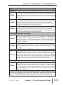
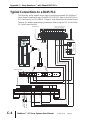
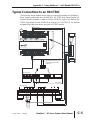
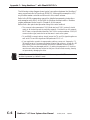
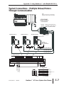
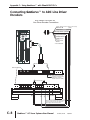
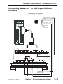
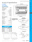
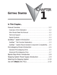
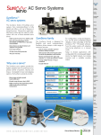
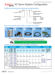
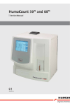
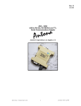
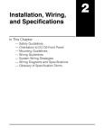
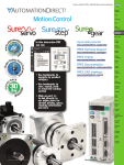
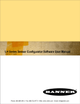
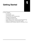
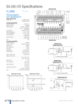
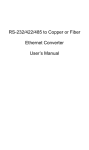
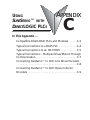
USING
SURESERVO™ WITH
DIRECTLOGIC PLCS
APPENDIX
C
B
In This Appendix ...
Compatible DirectLOGIC PLCs and Modules . . . . .C-2
Typical Connections to a DL05 PLC . . . . . . . . . . . .C-4
Typical Connections to an H0-CTRIO . . . . . . . . . . .C-5
Typical Connections – Multiple Drives/Motors Through
Communication . . . . . . . . . . . . . . . . . . . . . . . . . . .C-7
Connecting SureServo™ to ADC Line Driver Encoders .
. . . . . . . . . . . . . . . . . . . . . . . . . . . . . . . . . . . . . . .C-8
Connecting SureServo™ to ADC Open-Collector
Encoders . . . . . . . . . . . . . . . . . . . . . . . . . . . . . . . .C-9
Appendix C: Using SureServo™ with DirectLOGIC PLCs
Compatible DirectLOGIC PLCs and Modules
The following tables show which DirectLOGIC PLCs and modules can be used
with SureServo™ servo systems.
DirectLOGIC PLC s/Modules for Use with SureServo Systems
DL05 PLCs
D0-05AD
DL05 CPU, 8 AC in / 6 DC out, 110/220VAC power supply. Inputs: 8 AC inputs, 90-120 VAC,
2 isolated commons. Outputs: 6 DC outputs, 6-27 VDC current sinking, 1.0A/pt. max.,
1 common. 2 outputs are configurable for independent CW/CCW pulse train output or step and
direction pulse output up to 7KHz (0.5A/pt.).
D0-05DD
DL05 CPU, 8 DC in / 6 DC out, 110/220VAC power supply. Inputs: 8 DC inputs, 12-24 VDC
current sinking/sourcing, 2 isolated commons. Outputs: 6 DC outputs, 6-27 VDC current
sinking, 1.0A/pt. max., 1 common. 2 outputs are configurable for independent CW/CCW pulse
train output or step and direction pulse output up to 7KHz (0.5A/pt.) (not available when using
high-speed inputs).
DL05 CPU, 8 DC in / 6 DC out, 12/24VDC power supply. Inputs: 8 DC inputs, 12-24 VDC
current sinking/sourcing, 2 isolated commons. Outputs: 6 DC outputs, 6-27 VDC current
D0-05DD-D sinking, 1.0A/pt. max., 1 common. 2 outputs are configurable for independent CW/CCW pulse
train output or step and direction pulse output up to 7KHz (0.5A/pt.) (not available when using
high-speed inputs).
DL06 PLCs
D0-06DD1
DL06 CPU, 20 DC in / 16 DC out, 110/220VAC power supply, with 0.3A 24VDC auxiliary
device power supply. Inputs: 20 DC inputs, 12-24 VDC current sinking/sourcing, 5 isolated
commons (4 inputs per common). Outputs: 16 DC outputs, 12-24 VDC current sinking, 1.0A/pt.
max., 4 commons non-isolated (4 points per common). 2 outputs are configurable for
independent CW/CCW pulse train output or step and direction pulse output up to 10KHz
(0.5A/pt.) (not available when using high-speed inputs).
DL06 CPU, 20 DC in / 16 DC out, 12/24VDC power supply. Inputs: 20 DC inputs, 12-24 VDC
current sinking/sourcing, 5 isolated commons (4 inputs per common). Outputs: 16 DC outputs,
D0-06DD1-D 12-24 VDC current sinking, 1.0A/pt. max., 4 commons non-isolated (4 points per common).
2 outputs are configurable for independent CW/CCW pulse train output or step and direction
pulse output up to 10KHz (0.5A/pt.) (not available when using high-speed inputs).
DL05/DL06 High Speed Counter I/O Module
H0-CTRIO
C–2
DL05/06 High Speed Counter I/O Interface Module, 4 DC sink/source inputs 9-30 VDC, 2
isolated sink/source DC outputs, 5-30 VDC, 1A per point. Inputs supported: 1 quadrature
encoder counters up to 100KHz, or 2 single channel counters up to 100KHz, and 2 high speed
discrete inputs for Reset, Inhibit, or Capture. Outputs supported: 2 independently configurable
high speed discrete outputs or 1 channel pulse output control, 20Hz-25KHz per channel, pulse
and direction or cw/ccw pulses.
SureServo™ AC Servo Systems User Manual
2nd Ed, Rev B
08/2011
Appendix C: Using SureServo™ with DirectLOGIC PLCs
DirectLOGIC PLCs/Modules for Use with SureServo Systems (cont.)
DL105 PLCs
F1-130AD
DL130 CPU, 10 AC in / 8 DC out, 110/220VAC Power Supply. Inputs: 10 AC inputs, 80-132
VAC, 3 isolated commons. Outputs: 8 DC outputs, 5-30VDC current sinking, 0.5A/pt. max, 3
internally connected commons. 3 internally connected commons. 2 outputs are configurable
for independent CW/CCW pulse train output or step and direction pulse output up to 7KHz (@
0.25A/pt. max).
F1-130DD
DL130 CPU, 10 DC in / 8 DC out, 110/220 VAC Power Supply. Inputs: 10 DC inputs, 12-24
VDC current sinking/sourcing, 3 isolated commons. Outputs: 8 DC outputs, 5-30VDC current
sinking, 0.5A/pt. max, 3 internally connected commons. 2 outputs are configurable for
independent CW/CCW pulse train output or step and direction pulse output up to 7KHz (@
0.25A/pt. max) (not available when using high-speed inputs).
DL130 CPU, 10 DC in / 8 DC out, 12/24VDC Power Supply. Inputs: 10 DC inputs, 12-24
VDC current sinking/sourcing, 3 isolated commons. Outputs: 8 DC outputs, 5-30VDC current
F1-130DD-D sinking, 0.5A/pt. max, 3 internally connected commons. 2 outputs are configurable for
independent CW/CCW pulse train output or step and direction pulse output up to 7KHz (@
0.25A/pt. max) (not available when using high-speed inputs).
DL205 High Speed Counter I/O Modules
H2-CTRIO *
DL205 High Speed Counter I/O Interface Module, 8 DC sink/source inputs 9-30VDC, 4 isolated
sink/source DC outputs, 5-30VDC, 1A per point. Inputs supported: 2 quadrature encoder
counters up to 100KHz, or 4 single channel counters up to 100KHz, and 4 high speed discrete
inputs for Reset, Inhibit, or Capture. Outputs supported: 4 independently configurable high
speed discrete outputs or 2 channels pulse output control, 20Hz-25KHz per channel, pulse and
direction or cw/ccw pulses.
D2-CTRINT
Counter Interface Module, 4 isolated DC inputs, 1 pulse train output (cw) or 2 pulse train
outputs (cw,ccw) with DC input restrictions, accepts two up-counters when used with D2-240
or D2-250(-1) (one only with D2-230), or one up/down counter. (not available when using highspeed inputs).
Terminator I/O High Speed Counter I/O Module
Terminator I/O High Speed Counter I/O Interface Module, 8 DC sink/source inputs 9-30VDC,
4 isolated sink/source DC outputs, 5-30VDC, 1A per point. Inputs supported: 2 quadrature
encoder counters up to 100KHz, or 4 single channel counters up to 100KHz, and 4 high speed
T1H-CTRIO * discrete inputs for Reset, Inhibit, or Capture. Outputs supported: 4 independently configurable
high speed discrete outputs or 2 channels pulse output control, 20Hz-25KHz per channel, pulse
and direction or cw/ccw pulses. (Use with T1K-16B or T1K-16B-1 terminal base.)
DL405 High Speed Counter I/O Module
H4-CTRIO
DL405 High Speed Counter I/O Interface Module, 8 DC sink/source inputs 9-30VDC, 4 isolated
sink/source DC outputs, 5-30VDC, 1A per point. Inputs supported: 2 quadrature encoder
counters up to 100KHz, or 4 single channel counters up to 100KHz, and 4 high speed discrete
inputs for Reset, Inhibit, or Capture. Outputs supported: 4 independently configurable high
speed discrete outputs or 2 channels pulse output control, 20Hz-25KHz per channel, pulse and
direction or cw/ccw pulses.
* Note: The H2-CTRIO and T1H-CTRIO High Speed Counter I/O Interface Modules can also be
used to control the SureServo Servo System in PC-Based Control systems with Think & Do/Studio
or with our embedded WinPLC/EBC module plugged into the CPU slot of the DL205 base.
2nd Ed, Rev B
08/2011
SureServo™ AC Servo Systems User Manual
C–3
Appendix C: Using SureServo™ with DirectLOGIC PLCs
Typical Connections to a DL05 PLC
The following wiring diagram shows typical connections between the SureServo™
Servo System components and a DirectLOGIC DL05 PLC. Refer to the DL05 Micro
PLC User Manual, p/n D0-USER-M, Chapter 3: High-Speed Input and Pulse Output
Features, for detailed programming instructions when using the PLC for the Mode
30: Pulse Output function.
DL05 PLC programmed for
Mode 30: Pulse Output
D0-05DD PLC
AC(L) AC(N) C0
G
LG
X1
X0
X3
X2
C1
X4
X6
X5
C2
X7
Y1
Y0
Y3
Y2
Y5
Y4
+V
R
S
T
U
GND
L2
L1
24 VDC
–
C
N
2
V
W
P
D
C
C
N
3
ZIPLink Terminals
/OA
/OB /OZ
OB
COM- OCZ COM- OZ
COM-
PULSE V_REF /PULSE GND COM-
PULSE
SIGN
(+24V) PULL HI
DI6
MON2 MON1 VDD T-REF GND VCC OA
COM+
DI1
DO1-
DI2 COM+ GND GND
COM-
REVERSE LIMIT
DI7
DI8
FAULT STOP
C–4
DI1
DI7 DI6 DI5 DI3 PULL HI /SIGN SIGN
DI8
FORWARD LIMIT
DO4- DO5- DO5+
DO1+
DO4+ DO3- DO3+ DO2- DO2+ DO1- DO1+ DI4
SureServo™ AC Servo Systems User Manual
2nd Ed, Rev B
08/2011
PSP24-024S
C
N
1
L2
+
AC Power
L1
SERVO RDY
(TYPICAL)
Sureservo
24 VDC
Power Supply
120/240
VAC
AC Power
NEXT
+24V
SERVO ENABLE
DIR
0V
L1 L2
ENTER
GND
MODE
STEP
AUTOMATIOND IRECT
Appendix C: Using SureServo™ with DirectLOGIC PLCs
Typical Connections to an H0-CTRIO
The following wiring diagram shows typical connections between the SureServo™
Servo System components and a DirectLOGIC H0-CTRIO High Speed Counter I/O
Interface Module installed in either a DL05 or DL06 PLC option slot. Refer to the
CTRIO High-Speed Counter Module User Manual, p/n HX-CTRIO-M, for detailed
programming instructions when using the H0-CTRIO module.
0V
SERVO ENABLE
G
LG
0V
Y0
Y2
C1
Y5
Y7 Y10 Y12
C3 Y15 Y17
AC(L) AC(N) 24V C0
Y1
Y3
Y4
Y6
C2
Y11 Y13 Y14 Y16 N.C.
OUTPUT: 6-240V
Y
X
0
1
2
50 - 60Hz
3
INPUT: 12 - 24V
4
2.0A, 6 - 27V
5
6
7
10
2.0A
11
12
PWR: 100-240V
13
14
15
16
50-60Hz 40VA
17
20
D0-06DR
21 22
OK
23
A
3 - 15mA
LOGIC
B
CTR/TMR IN
9–30V5–12mA
DC/Pulse Out
5–36V1A
06
ERR
Y0
Y1
IN
A
B
K oyo
C
C0
X1
X0
X3
X2
X4
C1
X6
X5
X7
C2 X11 X13 X14 X16 C4 X21 X23 N.C.
X10 X12 C3
X15 X17 X20 X22 N.C.
D
M
0V
SERVO
READY
0V
STEP
DIR
YC
Y0
Y1
OUT
H0–CTRIO
0V
ZIPLink Kit Cable Connects
to SureServo Drive CN1
Connector
ZIPLink Terminals
08/2011
/OB /OZ
OB
SERVO ENABLE
COM- OCZ COM- OZ
COM-
PULSE V_REF /PULSE GND COM-
PULSE
SIGN
DI6
/OA
VDD
COM+
DI1
MON2 MON1 VDD T-REF GND VCC OA
COM-
REVERSE LIMIT
FORWARD LIMIT
DI7
DI8
DI2 COM+ GND GND
DI7 DI6 DI5 DI3 PULL HI /SIGN SIGN
DI8
FAULT STOP
2nd Ed, Rev B
DI1
PULL HI
DO1ZIPLink Terminals
DO4- DO5- DO5+
DO1+
DO4+ DO3- DO3+ DO2- DO2+ DO1- DO1+ DI4
SureServo™ AC Servo Systems User Manual
C–5
Appendix C: Using SureServo™ with DirectLOGIC PLCs
The following wiring diagram shows typical connections between the SureServo™
servo components and a DirectLogic DL06 PLC. Although this example is a PLC,
any Modbus master controller would work in this control scheme.
Refer to the DL06 programming manual for detailed programming instructions
and examples using Port 2 of the DL06 for Modbus communications. Modbus
register addresses can be found in Chapter 6 of this manual.
Below find a few quick-start tips when using this control method:
• The communication parameters P3-01 (Baud rate) and P3-02 ( protocol) should
match in all the devices and the multidrop network. Each device on this network
MUST have a unique Modbus identifier: Set P3-00 to a unique address. P3-05 (RS
communication type) must also be set the same in each servo system.
• To use RS485 communications, simply jumper the TX- and RX- signals together as
well as the TX+ and RX+ signals and set parameter P3-05 = 1.
• If your application needs to change speeds, positions, ramps, etc. frequently, P230 should be set to 5 to prevent excessive writes to flash memory. As with any EEtype memory, there is a finite number of times the hardware can be written to
before it will become damaged and fail. By setting the parameter to 5, the drive
uses the new values that are written but they are not set to flash memory, thereby
not prematurely damaging the drive.
NOTE: The value in P2-30 is NOT stored in flash memory and MUST be set each time
the drive is powered up (default is zero).
C–6
SureServo™ AC Servo Systems User Manual
2nd Ed, Rev B
08/2011
Appendix C: Using SureServo™ with DirectLOGIC PLCs
Typical Connections – Multiple Drives/Motors
Through Communication
Note:
Refer to Chapter 6 for more detailed
Modbus communications information.
RS-422/485
Communication
Connections
Terminal
Blocks
WHITE: RTS+
RS422 connections shown.
For RS485, jumper TXD+ to
RXD+, and TXD- to RXD-.
BLACK: RTSPINK: CTS+
LT BLUE: CTSGRAY: RXD+ *
PURPLE: RXD- *
LT GREEN: TXD+
D2-DSCBL-2
TXD+ :YELLOW
TXD- :YLW/BLK
RXD+ :RED
BRN/WHT: TXDYELLOW: 0V
MODBUS ADDR 1
MODBUS ADDR 2
AUTOMATIOND IRECT
MODE
MODBUS ADDR 3
AUTOMATIOND IRECT
MODE
ENTER
NEXT
AUTOMATIOND IRECT
MODE
ENTER
NEXT
Sureservo
L1
L2
L1
L2
L1
C
N
1
R
S
S
T
T
T
W
P
D
C
U
C
N
2
V
W
P
D
C
C
N
3
D04+ D03- D03+ D02- D02+ D01- D01+ D14- D11- D12- COM+GND GND VGND MON2 MON1 VDD T-REF GND VCC OA
D04- D05- D05+
D18- D17- D16- D15- D13- PULL HI /SIGN SIGN
TGND PULSE V-REF /PULSE GND COM-
/OA /OB
COM-
/OZ
C
N
1
L2
R
S
V
SureServo Drive
ENTER
Sureservo
R
U
* NOTE: CONNECT A 100-150 OHM
TERMINATION RESISTOR
ACROSS RXD+ AND RXD-
NEXT
Sureservo
C
N
1
RXD- :RED/BLK
GND :BROWN
U
C
N
2
C
N
2
V
W
P
D
C
C
N
3
OB
D04+ D03- D03+ D02- D02+ D01- D01+ D14- D11- D12- COM+GND GND VGND MON2 MON1 VDD T-REF GND VCC OA
COM- 0Z
D04- D05- D05+
D18- D17- D16- D15- D13- PULL HI /SIGN SIGN
TGND PULSE V-REF /PULSE GND COM-
/OA /OB
COM-
/OZ
ZIPLink
ZL-RTB50 &
ZL-SVC-CBL50-x
C
N
3
OB
D04+ D03- D03+ D02- D02+ D01- D01+ D14- D11- D12- COM+GND GND VGND MON2 MON1 VDD T-REF GND VCC OA
COM- 0Z
D04- D05- D05+
D18- D17- D16- D15- D13- PULL HI /SIGN SIGN
TGND PULSE V-REF /PULSE GND COM-
/OA /OB
COM-
/OZ
OB
COM- 0Z
SVC-MDCOM-CBL
SVC-MDCOM-CBL
SVC-MDCOM-CBL
ZL-RTB50 Terminals
COM-
COM- OCZ COM- OZ
SVC-MDCOM-CBL
ug
1
pl
REVERSE LIMIT
FORWARD LIMIT
FAULT STOP
PULSE V_REF /PULSE GND COM-
DI6
DI7 DI6 DI5 DI3 PULL HI /SIGN SIGN
DI7
DI8
DI8
DO4- DO5- DO5+
2
5
6
3
4
1
2
3
4
5
6
shell
IEEE 1394
6-pin Plug
2nd Ed, Rev B
08/2011
brown
brown/white
red
red/black
yellow
yellow/black
shield
GND
RS-232 TX
RS-422 RX+
RS-232 RX / RS-422 RXRS-422 TX+
RS-422 TXshield
Unterminated
Stripped & Tinned Wires
SureServo™ AC Servo Systems User Manual
C–7
Appendix C: Using SureServo™ with DirectLOGIC PLCs
Connecting SureServo™ to ADC Line Driver
Encoders
ADC Model TRD-Sxxx-VD
Line Driver Encoder Connections
Brown: Power
(Connect to external +5 VDC source)
(COM-)
Blue: 0 V
Black: OUT A
AUTOMATIOND IRECT
Purple: OUT /A
White: OUT B
MODE
(PULSE)
(/PULSE)
(SIGN)
Gray: OUT /B (/SIGN)
ENTER
Orange: OUT Z *
NEXT
Yellow: OUT /Z *
Sureservo
L1
L2
Shield: Ground
C
N
1
* No connections
R
S
T
U
V
W
P
D
C
C
N
2
C
N
3
ZIPLink Terminals
DO4+ DO3- DO3+ DO2- DO2+ DO1- DO1+ DI4
DI1
DI2 COM+ GND GND
MON2 MON1 VDD T-REF GND VCC OA
+24 VDC
/OA
/OB /OZ
OB
(Can power encoder here
if using a 24 VDC encoder;
make sure to connect
encoder common to COM-.)
(internal circuitry)
COM-
/PULSE
PULSE V_REF /PULSE GND COM-
PULSE
DI7 DI6 DI5 DI3 PULL HI /SIGN SIGN
SIGN
DI8
/SIGN
DO4- DO5- DO5+
COM- OCZ COM- OZ
See Note
*NOTE: Connect external +5 VDC power supply
common to COM-; encoder, servo drive, and
power supply must all connect to COM-.
C–8
SureServo™ AC Servo Systems User Manual
2nd Ed, Rev B
08/2011
Appendix C: Using SureServo™ with DirectLOGIC PLCs
Connecting SureServo™ to ADC Open-Collector
Encoders
ADC Model TRD-Sxxx-BD
Open-Collector Encoder Connections
Brown: Power source (+24 VDC)
(COM-)
Blue: 0 V
Black: OUT A
(PULSE)
AUTOMATIOND IRECT
White: OUT B
MODE
(SIGN)
ENTER
Orange: OUT Z
NEXT
Sureservo
L1
L2
Shield: Ground
C
N
1
R
S
T
U
V
W
P
D
C
C
N
2
C
N
3
ZIPLink Terminals
DO4+ DO3- DO3+ DO2- DO2+ DO1- DO1+ DI4
DI1
DI2 COM+ GND GND
MON2 MON1 VDD T-REF GND VCC OA
/OA
/OB /OZ
OB
+24 VDC (if using a 24 VDC encoder)
(internal circuitry)
COM- OCZ COM- OZ
COM-
PULSE V_REF /PULSE GND COM-
PULSE
DI7 DI6 DI5 DI3 PULL HI /SIGN SIGN
SIGN
DI8
PULL HI
DO4- DO5- DO5+
PULL HI
(if using the drive’s
internal power supply)
2nd Ed, Rev B
08/2011
SureServo™ AC Servo Systems User Manual
C–9
Appendix C: Using SureServo™ with DirectLOGIC PLCs
BLANK
PAGE
C–10
SureServo™ AC Servo Systems User Manual
2nd Ed, Rev B
08/2011