1
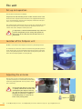
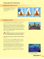
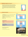
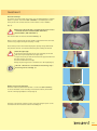
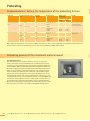
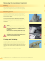
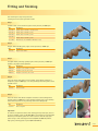
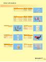
SYSTEM
in for2press system
Processing instructions
English
Please read these processing instructions and the associated user
manual carefully prior to using the product!
Contents
Introduction.........................................................................................
Important information .....................................................................
Safety information ............................................................................
3
3
3
The unit ....................................................................................
Set-up and operation .......................................................................
Location of the for2press unit .......................................................
Adjusting the air brake .....................................................................
4
4
4
4
Preparing the framework ........................................................
Preparing the tooth stump ..............................................................
Temporary moulds .............................................................................
5
5
5
Preparing the framework ........................................................
Insulating the plaster model...........................................................
Material thickness, connector cross-sections and
framework geometry.........................................................................
Connector cross-section design ....................................................
Mould showing distribution of chewing forces ........................
Basal rest mould on the gums .......................................................
Connector design*..............................................................................
6
6
Mould spruing ..........................................................................
Insulate mould plate with Vaseline ..............................................
Spruing..................................................................................................
Investment options............................................................................
8
8
8
8
Spruing version 1: Removal procedure..................................
Positioning in the mould plate.......................................................
9
9
6
6
6
7
7
Spruing version 2: Model over-pressing technique (size 9) . 10
Creating the duplicate model....................................................... 10
2/28
Spruing version 3: Model over-pressing technique mould
set MP (size 10) .....................................................................
Creating the duplicate model.......................................................
Positioning on the base plate .......................................................
12
12
12
Mixing and investment .........................................................
Controlling the expansion of the investment material.........
Investment .........................................................................................
14
14
15
Preheating ..............................................................................
Recommendation: Setting the temperature of the
preheating furnace ..........................................................................
Preheating process of the investment material mould .........
Filling capacity..................................................................................
Melting the material .......................................................................
16
Pressing process with for2press ...........................................
Attaching the press plunger ........................................................
18
18
Removing the investment material......................................
Soaking ...............................................................................................
Devesting process ............................................................................
20
20
20
Fitting and finishing..............................................................
20
Veneering with composites ...................................................
22
Cleaning ..................................................................................
23
Framework insertion .............................................................
Summary of potential bonding and fixing materials.............
24
24
Order information .................................................................
25
Troubleshooting ...................................................................
26
FAQ .........................................................................................
27
16
16
17
18
T: +49 (0) 73 09 / 8 72-4 41 · F: +49 (0) 73 09 / 8 72-4 44 · www.visio-lign.com · @: [email protected]
Introduction
The following instructions contain all the information needed to process
BioHPP in the for2press unit. The protocols listed here enable the manufacture of prosthetic work using BioHPP while maintaining the characteristics of the polymer in the end product.
The vacuum press system for2press automatically performs the pressing
process and subsequent cooling of the mould under pressure and under
vacuum.
Only use the system components of the for2press system, such as the
"brevest for2press" investment material, the "for2press filler" press
plunger, the "for2press mould set" investment material moulds and
the metal reinforcement ring.
Important information
Symbols:
The processing instructions include symbols as well as
!
special warnings,
with special processing tips to enable easier processing.
Safety information
Appropriate use:
The for2press system is intended to be used for the indications described in
the user manual. Any other use will be considered as improper use.
Use of heat protection gloves, dust mask and safety glasses is strongly
recommended when using this system.
User qualifications:
Users who work with the system must
• be appropriately trained for the relevant activities.
• know the relevant safety procedures.
It must be ensured that these processing instructions are always available for the user.
Please also note the operating and maintenance instructions for the
for2press vacuum press unit REF 140 0061 0.
3/28
The unit
Set-up and operation
(see the device instructions included)
Compressed air unit and inlet pressure of min. 4.5 bar to max. 6 bar
Ensure that the compressed air maintenance unit supplied with the basic
set is connected to the rear side of the for2press and that the inlet pressure is set to a maximum of 6 bar.
This compressed air maintenance unit also cleans the compressed air and
removes moisture from it. It thus protects the pneumatic sensors and
control units of the for2press vacuum press unit.
!
It is important to check beforehand whether any other users
may have changed the pressure setting. The dynamic air
inlet pressure in the cable must not fall below 4.5 bar or
exceed 6 bar.
Location of the for2press unit
BioHPP is not melted in the for2press unit but in a preheating furnace.
To avoid heat loss when the mould is moved from the preheating furnace
to the pressing unit, we recommend that the pressing unit is positioned
close to the preheating furnace. Transfer time to the pressing unit: maximum 10 seconds (comparable to casting alloys).
Adjusting the air brake
Prior to first use, the screws that operate the pressing table's brakes (to be found underneath the table)
need to be gently tightened. You only need to check
this occasionally.
!
4/28
1
2
The pressing table must not come down
too quickly, otherwise the moulds could
be damaged by the impact. If this happens, the air brake should be tightened
using the set screws. Tip: a weight of
around 600 g helps to control the air
brake on the pressing table!
T: +49 (0) 73 09 / 8 72-4 41 · F: +49 (0) 73 09 / 8 72-4 44 · www.visio-lign.com · @: [email protected]
= approx. 3 x
Preparing the framework
Preparing the tooth stump
In order to provide optimum support to the
framework, a chamfer or shoulder preparation is required (Fig. 1+2).
A tangential preparation is not recommended (Fig. 3).
1
2
3
Temporary moulds
To produce temporary moulds, we recommend the use of all conventional
waxes and modelling resins that burn completely without residue.
1
Modelling resin is suitable for making temporary moulds for crown and
bridge frameworks and superstructures, e.g. bar assemblies or Toronto
bridges, but not for over-pressing titanium bases; these abutments should
be moulded in wax. Resin should be chosen which does not significantly
increase in volume during the burning process, so that the investment
materials are not put under too much stress. Therefore, when resins are
used, a wax layer should also be applied to compensate for the expansion,
particularly for very large frameworks.
!
Caution!
Modelling resin must not be used for titanium abutments as
the preheating temperature of 630°C is not sufficient for
the modelling resin to burn without leaving any residue.
When producing the framework for subsequent veneering with composite
veneers, the temporary mould for the framework must be anatomically
scaled down.
The minimum material thickness for BioHPP is 0.6 mm. For optimum
accuracy in the fit around the preparation margin (crown margin), the
circular modelling in that area needs to be increased. This area can be
tapered and reduced to 0.3 mm after the pressing process.
When producing temporary moulds for back protection plates for veneering, the transition must be positioned outside the functional surface
for veneering. Sharp-edged transitions in the mould must be avoided.
Moulding scalloped edges has proven successful for veneer bridges in the
anterior and posterior areas in order to increase stability. (Fig. 1)
22
It is recommended that retaining elements (coarse retention splinters or
large retention beads) are also attached to the surface to be veneered
(Fig. 2).
Evenly distributed retention crystals.
Image: Dentec Allergielabor Ehrenkirchen,
Jens-Christian Fehsenfeld, (DE)
5/28
Preparing the framework
Insulating the plaster model
Conventional wax insulation has proven to be suitable when using
modelling wax. If the temporary mould is made of modelling resin,
Vaseline must be used for the insulation.
Material thickness, connector cross-sections and framework geometry
BioHPP
Minimum circular
framework thickness
Minimum occlusal
framework thickness
Connector thickness
Geometric proportion of pontics
(horizontal/vertical)
Anterior crowns
Posterior crowns
Primary telescop- Secondary teleic crowns
scopic crowns
4-unit anterior
bridges
4-unit posterior
bridges
Bar attachments
> 0.6–0.7 mm
> 0.6–0.7 mm
> 0.6–0.7 mm
> 0.6–0.7 mm
> 0.6–0.7 mm
Abutment tooth
> 0.6–0.7 mm
> 0.8 mm
> 0.6–0.7 mm
> 0.8 mm
> 0.6–0.7 mm
> 0.6–0.7 mm
> 0.6–0.7 mm
Abutment tooth
> 0.6–0.7 mm
> 0.8 mm
—
—
—
—
> 12 mm2
> 14 mm2
—
—
—
—
—.
40/60 %
40/60 %
—
Connector cross-section design
Posterior region connectors:
Anterior region connectors:
min. 14 mm²
min. 12 mm²
1
min.
14 mm2
In the posterior region, the connector thickness of the wax model between
pontics or between the pontic and the crown must cover a minimum area
of 14 mm². In the anterior region, the connector thickness of the wax
model between pontics or between the pontic and the crown must cover
a minimum area of 12 mm². The distribution between the vertical and
horizontal areas must be approx. 60% to 40%.
ca.
3.5 mm
The largest framework diameter from the occlusal to the basal area should
be along the axis of the central fissure. This is important for the stability of
the framework. The elastic behaviour is thus restricted by up to 2 pontics,
which also ensures the adhesive bond between the veneering resin and the
BioHPP.
Mould showing distribution of chewing forces
As shown in figures 1 and 2, the largest diameter from the occlusal to
the basal areas should be along the axis of the central fissure. This is
important for the stability of the framework. Creating a shape like a flute
mouthpiece should be avoided.
6/28
1
T: +49 (0) 73 09 / 8 72-4 41 · F: +49 (0) 73 09 / 8 72-4 44 · www.visio-lign.com · @: [email protected]
2
ca.
4 mm
Basal rest mould on the gums
We recommend not veneering the basal application of the bridge pontics
on the gingiva of the alveolar ridge with composite veneers. This area must
be designed from BioHPP in order to ensure the greatest possible strength
in the vertical extension. In the transitions from the composite veneer
to the BioHPP framework material, an undercutting retentive end strip
must be modelled using a wraparound technique (Fig. 3). The BioHPP has
extremely good polishing properties, making direct contact to the gingiva
possible.
3
Connector design*
Oral view
• Veneering resin in the buccal basal area should not project beyond the
basal BioHPP layer
• Even veneering thickness, supported everywhere by framework
• Veneering should not taper off sharply
• Veneering in the connector area should not have wide or sharp
separations
• The basal pontic area should not be veneered
• Height: > 3.7 mm
• Width: > 3.5 mm
Veneering (composite):
• Even layer thickness
• 1–2 mm
• Round cusp formation (anatomically shaped, but not too
angled)
4
Palatinal view
5
Framework (BioHPP):
• Anatomically shaped
• Supports the veneering
• Round design
Section
Tooth stump preparation options:
• Wedge with rounded interior edge
• Accentuated chamfer
Not veneered
5
* University of Regensburg UKR, Dr. Rosentritt (DE)
Image: Schwindt Dentallabor, Landau/Pfalz (DE)
7/28
Mould spruing
Insulate mould plate with Vaseline
!
To facilitate the subsequent removal of the mould plate or
the press plunger spacer from the investment material, we
recommend slightly greasing the mould plate and the vertical press plunger spacer with Vaseline.
1
Spruing
!
Do NOT use casting bars or casting pears!
2
Only a few short sprues with a larger diameter (e.g. 4–5 mm) should be attached to
the areas of the mould that have the largest volume. For larger structures, the sprues
should be positioned symmetrically and evenly on at least every other element, so
that the pressure during the cooling process is evenly distributed.
It is recommended that a bar (diameter 2 mm) made from hard wax is placed so that
it provides a dorsal link on the section between the last elements, thus preventing
potential tension.
Add two air channels leading from the last two elements towards the mould plate.
Summary of the most important spruing parameters
3
4
Single crown, individual abutment, 4-unit bridges, model over-pressing technique (PressOverModel)
Wax wire diameter
Sprue length
Layout of attachment points
Distance between several objects
Distance between the mould and the edge and top of the ring
4–5 mm
max. 5
Conical,
with no sharp edges or corners
3–3.5 mm (except model over-pressing)
10 mm
In Figures 3 + 4, an individual abutment is sprued using the "perfect2press" (REF
430F2P30) specially formed, spiral sprue. These special sprues are very well suited
for use with BioHPP granules. They prevent individual granules from falling into the
mould too soon and ensure homogenisation during the pressing process as well as
preventing air pockets.
Investment options
Investment can be carried out in two
different ways. Either the resin or wax
mould is taken from the master model
and completely invested (Fig. 5), or the
mould is made using an investment material duplicate model as per the model
casting technique and subsequently
invested (Fig. 6).
5
Removal procedure
8/28
6
Model over-pressing technique
T: +49 (0) 73 09 / 8 72-4 41 · F: +49 (0) 73 09 / 8 72-4 44 · www.visio-lign.com · @: [email protected]
Spruing version 1: Removal procedure
Positioning in the mould plate
To reduce the risk of the mould bursting, as much of the investment material as possible should remain on the object to be pressed. If the hollow
space in the mould is too large, this can lead to instability resulting in
damage to the mould wall.
Model pressing: for some moulds/indications, e.g. telescopic secondary designs, the modelling of the secondary part is performed on an investment
material duplicate model. In this case, it is important that the investment
material model is significantly reduced in order to provide as much space
as possible for the investment coverage. This significantly reduces the
risk of the mould bursting – see the chapter on the model over-pressing
technique.
1
2
To obtain flawless pressing results, the following points must be observed:
• The object must be placed outside the heat centre (Fig. 1)
• The distance between the object and the inside of the metal ring must
be at least 5 to 10 mm (Fig. 2)
• The distance between the object and the upper edge of the mould ring
must be at least 10 mm (Fig. 3)
5 - 10 mm
3
10 mm
!
No sharp transitions to the objects.
!
In order to avoid the risk of mould separations in
one plane, it is recommended that, when moulding several, larger objects, these are placed in the
mould at different heights.
9/28
Spruing version 2: Model over-pressing technique (size 9)
Creating the duplicate model
Recommended concentration:
65–75%
65–75%
1
2
3
4
Investment material model
Investment coverage
The EBM model can be removed from the mould after 25 min.
5
6
The EBM should now be reduced and then dried at max. 80 °C for 30 min.
Minimum framework thickness:
Secondary telescope:
Secondary constructions:
circular
occlusal
> 0.6–0.7 mm
> 0.6–0.7 mm
> 0.8 mm
> 0.8 mm
7
The transitions from the veneering
composites to the BioHPP should be
made using a wraparound technique, showing the 'undercut'.
10/28
8
It is recommended that the basal
and vertical aspects of the EBM
model are reduced to the minimum
size required.
T: +49 (0) 73 09 / 8 72-4 41 · F: +49 (0) 73 09 / 8 72-4 44 · www.visio-lign.com · @: [email protected]
Investment mould set size 9
Summary of mixing parameters:
Model over-pressing technique
Wax wire diameter:
Sprue length:
Design of attachment points:
Distance between several
objects:
Distance between the mould
and the edge and top of the
ring
4–5 mm
max. 5 mm
no sharp edges or corners
—
9
10
10 mm
It is recommended that retentions
are attached to the surface to be
veneered.
11
It is recommended that a bar made
from hard wax is placed at the end.
For the investment coverage, 3 bags
of Brevest for2press (total 630 g) and
159 ml of Bresol (concentrate & dist.
H2O) for2press are required.
13
It is important to use short sprues
for spruing.
12
It is recommended that the sprues
are attached to the radius of the
press plunger reservoir.
14
11/28
Spruing version 3: Model over-pressing technique mould set
Creating the duplicate model
Recommended dosage of Bresol for2press with dist. water:
1
Recommended concentration:
65–75%
65–75%
Investment material model
Investment coverage
Mixing ratio:
For the investment coverage, three 210 g bags (a total of 630 g of Brevest
for2press with 159 ml of Bresol for2press) are required.
Do not use any casting pears, instead use wax sprues that are as short
and thick as possible, or the optional spiral-shaped perfect2press wax
sprues. Figure 1 shows the investment material duplicate model made from
Brevest for2press.
After pouring out the silicone duplicate, the model needs to dry for at least
30 min. The model can then be removed from the silicon duplicate mould.
The model can also be dried at a maximum of 80°C for 30 min.
Positioning on the base plate
It is recommended that the underside of the model is prepared with either
wax or modelling material, as appropriate (Fig. 2). A small gap should be
left under the investment material model, to be filled with the investment
material in the coverage process. This ensures a sufficient bond between
the model and the investment coverage.
To fix the sprues to the press plunger spacer, simply shorten them using
a hot modelling knife. (Fig. 3). The investment material model must be
placed in the centre of the base former, leaving a circular space between it
and the metal ring of at least 5 mm. This leaves enough space for coverage
with the investment material.
The transparent height limiter with the access window is slid sideways
onto the base plate. The window enables the press plunger spacer to be
more easily held in place from all sides.
12/28
2
3
4
T: +49 (0) 73 09 / 8 72-4 41 · F: +49 (0) 73 09 / 8 72-4 44 · www.visio-lign.com · @: [email protected]
MP (size 10) Investment mould set MP size 10*
Positioning in the mould plate
The centring aid for the press plunger spacer is simply attached to the
transparent height limiter.
5
Using the centring aid, the press plunger retainer is aligned precisely in the
middle of the wax sprues. The transition from the cylindrical to the conical
section of the press plunger spacer marks the maximum depth.
The wax sprues should then be fixed with the press plunger retainer.
After the press plunger spacer has bonded with the wax sprues, the centring aid can be lifted off the top.
After the centring aid and the height limiter have been removed, the
silicone fixing ring can be attached to the base plate. The round groove on
the silicone fixing ring fits precisely into the base plate.
9
6
7
8
10
* only possible with for2press 2 unit
13/28
Mixing and investment
Controlling the expansion of the investment material
General mixing ratios
Recommended dosage for Bresol for2press investment material liquid.
210 g of Brevest for2press (1 bag) = 53 ml of Bresol for2press liquid
Brevest for2press investment material has been specially developed for
processing BioHPP with the for2press unit.
Quantity
Mixing concentrate
210 g (size 3)
Bresol for2press
liquid
420 g (size 9)
distilled water
Bresol for2press
liquid
630 g (size 10)
distilled water
Bresol for2press
liquid
55%
29
24
58
48
87
72
70%
37
16
74
32
111
48
100%
53
0
106
0
159
0
Recommended concentrations
Removal technique
50% to 55% liquid = single crowns and bridges
70% to 80% liquid = secondary parts (telescopic) and tertiary constructions
Model over-pressing technique
65% to 75% liquid = investment material for over-pressing technique
If you thin the mixing liquid with demineralised water, this will reduce expansion.
All values are intended as a guide. The precise adjustment of the concentrate is to
be done based on the prevailing environmental conditions and indications in the
laboratory.
Mixing the investment materials:
Investment materials and liquid are to be stirred by hand for approx. 30 seconds.
Vacuum mixer:
We recommend that where possible, you use a prevacuum (approx. 10 sec.)
Rpm: approx. 390 r/min.
Mixing time: 90 seconds under vacuum
14/28
distilled water
T: +49 (0) 73 09 / 8 72-4 41 · F: +49 (0) 73 09 / 8 72-4 44 · www.visio-lign.com · @: [email protected]
Investment
Removal technique
To prevent air pockets inside the crowns, it is recommended that a suitable
brush or a special "transfuser" (REF 390S0001) is used during the investment process. This ensures that the crown interior is free of bubbles.
1
(Fig. 1).
!
When using a metal mould, a protective fleece liner at least
1 mm thick should be attached. (REF 360 F2PV 1,
REF 360 F2PV 2, REF 360 F2PV 3)
2
The whole mould can then be filled with EBM (Fig. 2).
After a 25 min. setting time, the hot mould is removed from the resin base
former using a slight turning motion (Fig. 3 and 4).
Please always remove the mould keeping the opening facing downwards.
This prevents the risk of investment material parts entering the mould.
!
Check the right angle
To ensure that the pressing process runs smoothly, the mould
needs to be kept straight and at a right angle.
It may be necessary to trim the mould on the opposite side from
the filler opening, to ensure
that the mould remains straight
during the pressing process. It should be at a 90° angle (Fig. 5).
4
5
90
°
If the size 3 mould set is used without a metal ring, only a
silicone ring can be used (Fig. 3).
3
Model over-pressing technique
Once the metal ring has been lined with a 1 mm insert (REF 360F2PV1),
it can be filled with a total of 630 g of investment material, mixed with
159 ml of mixing liquid (65% to 75%). (Fig. 6)
Once the coverage has cured for 25 min., the press plunger spacer can be
removed from the investment material mould (Fig. 7).
6
7
15/28
Preheating
Recommendation: Setting the temperature of the preheating furnace
Application
Recommended max. temperature
Modelling
material
Heating-up rate
Waiting times/
mould size Ø
3
(16 cm)
Over-pressing titanium
bases
All other applications
Speed
Wax
Directly into the hot
furnace
Conventional
Wax
8°C/min.
Stopping times
at 290°C
at 580°C
Directly into the hot
furnace
630°C
850°C – Speed
900°C
850°C – Conventional
900°C
Wax
Resin
Wax
Resin
8°C/min.
Stopping times
at 290°C
at 580°C
Benefits
9 + 10
(26 cm)
Up to four hours, faster,
more delicate structures can be devested.
45 min.
45 min.
60 min.
60 min.
smoother surface, more
stable mould
45 min.
45 min.
60 min.
60 min.
Next, reduce the temperature of the furnace to 400°C and hold for an hour to allow the BioHPP to melt. When using a metal ring,
the hot mould can be transferred directly into a second furnace preheated to 400°C (time-saving).
Preheating process of the investment material mould
Speed heating process:
The setting time of the investment material is 25 min. For the speed
process, the mould is then placed directly into a preheating furnace that
has been set to the end temperature. The optimum preheating temperature
is around 850°C–900°C. At this temperature, the investment material has
maximum stability due to the fused quartz. The preheating temperature of
630°C is only used when investing titanium parts such as elegance abutments. At 630°C, the formation of an oxide layer is minimised. The press
plunger must also run through the same entire preheating process as the
mould. After the holding time at the end temperature of 45 min. for a size
3 mould and 60 min. for a size 9 mould, the furnace is cooled to 400°C and
then held for another 60 min. The max. cooling speed of 5°C/min must not
be exceeded as this could affect the stability of the investment material
mould. This cooling speed is maintained if the furnace door remains closed
the whole time. The mould is now ready for the BioHPP melting process.
16/28
T: +49 (0) 73 09 / 8 72-4 41 · F: +49 (0) 73 09 / 8 72-4 44 · www.visio-lign.com · @: [email protected]
Preheating process of the investment material mould
Conventional heating process:
After allowing to set for 25 min., the mould can be placed in the cold
preheating furnace. The max. heating-up rate of 8°C/min should not be
exceeded. In order to precisely control the expansion of the investment
material during the conventional heating-up process, the guide times of
290°C for 45 min. and a second stage of 580°C for another 45 min. must
be adhered to. Once the end temperatures of 630°C and 850°C have been
reached, the holding time for a size 3 mould is at least 45 min. and for a
size 9 mould, at least 60 min. If several moulds are preheated at the same
time, the holding time per mould increases by around 10 minutes. After
this holding time, the mould is slowly cooled down, with the furnace door
shut, to 400°C at a speed of 5°C per minute.
When using a metal ring, the mould can be transferred directly into a
second furnace at 400°C.
!
Caution!
When investing titanium patterns, such as the individual
BioHPP elegance abutment, a maximum end temperature of
630°C must not be exceeded, as otherwise an Alpha Case
layer will form!
Filling capacity
Wax/BioHPP granules conversion table
BioHPP delivery form
Size 3 base mould with 16 mm press Size 9 base mould with 20 mm press Size 9 base mould + size 10 with
plunger diameter
plunger diameter
26 mm press plunger diameter
Mould weight
<1g
<2g
<3g
<4g
>5g
Granules
3g
max. 4.5 g
7.5 g
max. 9 g
smoother surface, more stable mould
15 mm pellet (4 g each)
1 pellet
1 pellet
2 pellets
2 pellets
25 mm pellet (15 g each)
not possible
3 pellets
1 pellet
17/28
Preheating
Melting the material
Fitting the BioHPP disposable press plunger to the mould
Once the mould has been in the preheating furnace for an hour at 400°C,
the sprues can be filled with granules or pellets. It is then put back in the
preheating furnace for another 20 min. (filled with BioHPP) at 400°C.
!
Melted or used material should never be used.
The material would degrade during another melting process and
important physical qualities would be lost. If the melting time
or temperature is exceeded, the BioHPP will be darker than at
the beginning of the process.
Melting time (BioHPP): 20 min.
!
1
2
Note: if the material turns darker, it can no longer be used
and must be replaced.
Pressing process with for2press
Attaching the press plunger
When fixing the mould with the disposable press plunger (for2press filler),
the surface with the identification mark must face upwards (Fig. 1). This
ensures that the rounded edge of the plunger goes into the mould. This
prevents the plunger from tilting during the pressing process (Fig. 2).
1
The mould containing the melted BioHPP is then immediately transferred
into the pressing unit. Please avoid placing the preheating furnace and the
pressing unit a long way apart!
2
90
°
Before pressing with for2press
The set parameters, such as the pressing force or the vacuum time, must
be checked before each pressing process.
18/28
T: +49 (0) 73 09 / 8 72-4 41 · F: +49 (0) 73 09 / 8 72-4 44 · www.visio-lign.com · @: [email protected]
Pressing process with for2press
Attaching the press plunger
Inlet pressure: 4.5–6 bar
Vacuum time (BioHPP): 3 minutes (preset) for2press
5 minutes (preset) for2press 2
3
Force:
Mould size
Press plunger diameter
in mm
Force in bar
Size 3
16
2.5
Size 9
26
4–5
Size 10
26
4–5
The mould assembled for the pressing process is placed on the pressing
table of the for2press unit. Manually closing the pressing chamber by
moving the pressing table upwards with both hands starts the pressing
process, which runs automatically for 40 minutes, including the cooling
phase.
4
The vacuum chamber is automatically evacuated before the pressing
chamber is closed. The status light changes from blue to red and the pressing process begins once the maximum vacuum has been reached.
Push the pressing table firmly upwards until the silicon seal fits all the
way round and the LED status light changes from blue to red.
Once the pre-set vacuum time has finished, the pressing table will automatically lower into the cooling position and the cooling phase will start,
while maintaining the pressing force.
The cooling phase under pressure lasts for 40 min.
The whole pressing process finishes with an acoustic signal, the LED display changes from red to blue and the press plunger is automatically raised
into the stand-by position.
The pressed mould can now be removed from the unit.
The unit is ready for the next pressing process.
!
Interrupting the programme while it is running using the
'Stop programme' button, just to save time, should always
be avoided. This button stops the whole programme. Prematurely interrupting the pressing time would have a negative
effect on the pressed material's physical properties. The
'Stop programme' button should only be used if, for example, the mould in the unit is not straight or a vacuum
cannot be generated due to dirt on the silicone seal.
19/28
Removing the investment material
Soaking
Soaking the mould for approx. 10 min. in a water bath makes the devesting process easier and significantly reduces the amount of dust generated.
Devesting process
The mould can be roughly devested using a hammer. The remaining investment material must be removed with a pneumatic devesting chisel. No
distortion takes place, such as with dental casting alloys, due to the elastic
material properties of BioHPP.
1
The rest of the investment material is sandblasted with 110 µm aluminium oxide grit at 2.5 bar. During the sandblasting process, the distance
between the object and the jet nozzle must be at least 3 cm (Fig. 2). If the
distance is any smaller, parts of the resin could become heated
and damaged.
!
Caution!
When using titanium bases that can be over-pressed (elegance abutment) for individual abutments, the remaining
investment material must be removed using 50 µm polishing
beads instead of 110 µm Al2O3 at a sandblasting pressure of
2.5 bar (Fig. 3).
Abrasives must not be used on the abutment joints. A cover
can be made for this section using a bolted-on laboratory
analogue. It is recommended that the remaining investment
material is loosened in an ultrasound bath.
!
The mould rings do not fit into the normal devesting presses
but can be easily removed from the mould.
Fitting and finishing
2
3
4
For wide-span objects, it may be beneficial if the sprues are not removed
during the fitting process. These can provide an extremely firm hold. After
fitting, the sprues can be most easily removed with cross-toothed mills.
Generally, the object is fitted to the stumps without using occlusal spray or
similar aids, as these chemical substances are difficult to remove from the
objects.
A perfect high gloss polish ensures optimum surface quality.
20/28
T: +49 (0) 73 09 / 8 72-4 41 · F: +49 (0) 73 09 / 8 72-4 44 · www.visio-lign.com · @: [email protected]
Fitting and finishing
The following five steps using selected
rotating tools will lead to optimum results:
Step 1
1
Carbide cutter, coarse serration, light contact pressure, 6–8000 rpm.
REF
Designation
H200 M8 23
Carbide cutter 2.3 mm Ø – rounded conical
H272 M8 14
Carbide cutter 1.4 mm Ø – garnet
H274 M8 40
Carbide cutter 4.0 mm Ø – garnet
H237 M8 23
Carbide cutter 2.3 mm Ø – garnet
350 00M2 5
Diamond disc 0.25 mm Ø Giflex-TR Master x-tray
2
Step 2
Diagen-Turbo-Grinder, green, light contact pressure, 6–8000 rpm.
REF
Designation
34000200
Diagen-Turbo-Grinder
Step 3
Ceragum rubber polishing cylinder, light contact pressure, 6–8000 rpm.
Caution: very light contact pressure.
REF
Designation
PWKG0650
Ceragum coarse cylinder, 6 x 19 mm
PLKG2250
Ceragum coarse lens, 22 x 4 mm
PRKG2250
Ceragum coarse wheel, 22 x 4 mm
3
Step 4
Goat-hair brush with pumice stone powder, at the dental technician's
workplace, approx. 5000 rpm, or on the polishing lathe with pumice stone
powder level II.
REF
Designation
35000610
Goat-hair brush
4
Step 5
Goat-hair brush with Abraso-Starglanz and then cotton buffing wheel
without polish 6–8000 rpm on the handpiece (Image 5a) or wool buffing
wheel without polish on the polishing lathe level II (Image 5b).
REF
Designation
52000163
Abraso-Starglanz
5a
5b
Important:
To achieve an optimum surface when making primary telescopes, the use
of special parallel cutters for BioHPP (REF H 137 M 823) is recommended.
After that, immediately polish the contact surface with the high-gloss
polish using a short-haired goat-hair brush (REF 350 0061 0) and the
high-gloss polishing paste Zi-polish (REF 360 1002 5).
21/28
Veneering with composites
Only composite veneers that harden without additional thermal treatment
may be used. The bredent composite veneer with all the visio.lign system
components has proven to be most suitable. This has been shown by numerous scientific studies.
1
Mechanical retentions in the form of beads or splinters have been proven
to improve the bond strength between BioHPP and the composite veneer
(Fig. 1).
2
The following order must be followed when conditioning the BioHPP
surface.
1. Blast with 2.5 bar and 110 µm Al2O3
2. Do
not steam off!
3. Thinly apply the visio.link
bonding agent according to the UM*
and polymerise (Fig. 2)
4. Apply opaquer according to the UM* and polymerise
5. Apply the composite veneer according to the UM*; potentially use the
visio.lign system veneers.
* UM = visio.lign user manual
In order to prevent undesired stresses or warpage in the framework, it is
advisable to separate the individual veneers up to the opaquer and only
combine them after polymerisation (e.g. with crea.lign). When using novo.
lign veneers, it is also important to separate these and only add the crea.
lign after final polymerisation.
Bond strength according to DIN EN ISO 10477/University of Jena
[MPa]
Bonding strength
2
40
30
Material
24.10
40.10 38.55
38.30 38.30
26.53
Mean values (after 25,000 LW)
20
10
0
Framework material
breCAM BioHPP
without retentions
for2press BioHPP
Retention beads
for2press BioHPP
Retention splitters
Studies by University of Jena, University of Cologne, University of Zurich, University of Munich
We recommend coating the exposed areas of the framework
and scalloped sections with a thin layer of crea.lign Transpa
so that intraoral cleaning is more convenient.
22/28
1 day 37°C
T: +49 (0) 73 09 / 8 72-4 41 · F: +49 (0) 73 09 / 8 72-4 44 · www.visio-lign.com · @: [email protected]
Cleaning
A steam blaster may only be used briefly and with a large clearance
between the nozzle and the BioHPP surface for final cleaning. Cleaning is
best done using ultrasound baths and pin cleaning units (e.g. Sympro by
Renfert) with a bath temperature of max. 40°C. Highly corrosive solutions
may not be used.
Recommended preparation of over-pressed elegance abutments
The preparation of customised elegance abutments can be
done using steam sterilisation (autoclave) and the vacuum
process. To do so, a triple fractionated pre-vacuum can be
generated with a sterilisation time of 4 minutes and a temperature of 134°C +/- 1°C.
Intraoral cleaning
The surfaces made from BioHPP may only be cleaned mechanically using
an ultrasound scaler if the resin tips approved for the implant technique
are used. The use of abrasives such as Air-Flow with gentle Air-Flow Plus
or Perio abrasives is possible but the surface must be mechanically polished, as with composite veneers. The Super Snap Set from Shofu is a suitable polishing material.
It is best if the patient cleans their teeth using a soft to medium toothbrush.
Extraoral cleaning
Cleaning is best done mechanically, with a soft to medium toothbrush,
using an ultrasound bath or a pin cleaning unit. When using an ultrasound
bath for 1 minute, the temperature must not exceed 40°C.
Steaming off delicate, removable frameworks made from BioHPP can put
parts of them under thermal stress and pressure.
Cleaning solutions should only be added in very small concentrations.
Do not steam off!
23/28
Framework insertion
Summary of potential bonding and fixing materials
Fixing systems**
BioHPP crowns and bridges to...
Metal/alloy
abutments
permanent
Adhesive – with conditioning/primer using composite fixing cement, e.g. Panavia F 2.0 (Kuraray),
VarioLink II (Ivoclar), NX-3 (Kerr)
Self-adhesive composite fixing cement 110 µm jet,
e.g. Rely X Unicem
(3M Espe)
Glass ionomer cement, e.g. Ketac Cem (3M Espe)
Zinc phosphate cement (e.g. Harvard)
temporary
Zinc oxide, eugenol-free cement
(Tempbond by Kerr)
A-Silicone-based fixing cement
(Tempsil 2 by Coltène Whaledent)
Fixing type
Zirconium diox- BioHPP abutide abutments
ments
✓
✓
X
✓
✓
✓
✓
X
●
●*
●
✓
●*
●
✓
●
●
✓
X
X
●*
X
X
X
✓
✓
✓
✓
X
Fixing systems**
BioHPP abutment with framework materials made from...
Adhesive – with conditioning/primer using composite fixing cement, e.g. Panavia F 2.0 (Kuraray),
VarioLink II (Ivoclar), NX-3 (Kerr)
Self-adhesive composite fixing cement 110 µm jet,
e.g. Rely X Unicem
(3M Espe)
Glass ionomer cement, e.g. Ketac Cem (3M Espe)
Zinc phosphate cement (e.g. Harvard)
temporary
✓ = optimum
Zinc oxide, eugenol-free cement
(Tempbond by Kerr)
A-Silicone-based fixing cement
(Tempsil 2 by Coltène Whaledent)
K = only to be used for crowns
Zirconium
dioxide
24/28
BioHPP
e.max
(lithium
disilicate/lithium silicate)
silanised
✓
✓
✓
✓
K
●
✓
✓
✓
X
X
X
X
●*
●
✓*
●*
●
✓*
●
●
●
X
X
X
X
✓
✓
✓
X
● = generally possible
X = not recommended
X = not released
**BioHPP TU, BioHPP ds 2 TU, breCAM.BioHPP TU, breCAM.BioHPP TU dentin shade 2 are officially released to be used for
•
•
•
•
•
•
•
(dentine,
enamel)
use visio.link on
BioHPP
✓
use visio.link on Dental alloys
BioHPP
permanent
Tooth structure
the fabrication of temporary crowns and bridge structures with max. 2 pontics (max. 6 month wearing time).
for removable denture indications in conjunction with telescopic crowns and/or implants for the usual life-span of those appliances (5-10 years).
Fully anatomical temporary crowns and bridges (max. 2 pontics, connector cross-section in the anterior tooth min. 12 mm², posterior tooth min.14 mm²)
Temporary Crowns copings and bridges substructures cemented for composite veneering (max.2 pontics)
Removable telescopic primary and secondary crowns and frameworks
Secondary bar structures on primary bars made of titanium alloy, CoCr alloys, zirconium dioxide
Fabrication of implant-supported, screw-retained restorations, wearing period of up to 180 days (recall interval), veneered with or without composite or resign.
T: +49 (0) 73 09 / 8 72-4 41 · F: +49 (0) 73 09 / 8 72-4 44 · www.visio-lign.com · @: [email protected]
* Only use with a preparation angle up to 5°
Fixing type
Order information
perfect2press sprue
REF 430F2P30
Bresol for2press liquid
1000 ml liquid for REF 520F2PL2
the investment
material
for 2press
Disposable press plunger
for2press filler
16 mm
REF 570F2P16
26 mm
REF 570F2P26
BioHPP (granules)
dentine shade 1
(white)
dentine shade 2
(tooth-coloured)
20 g
REF 54TF2PB2
REF 54TF2P22
100 g
REF 54TF2PB3
REF 54TF2P23
BioHPP pellets
dentine shade 1
(white)
dentine shade 2
(tooth-coloured)
Ø 25 mm
75 g (5 x15 g)
REF 54TF2PB4
REF 54TF2P24
Ø 25 mm
150 g (10 x 15 g)
REF 54TF2PB5
REF 54TF2P25
Ø 15 mm
20 g (5 x 4 g)
REF 54TF2PB6
REF 54TF2P26
Ø 15 mm
40 g (10 x 4 g)
REF 54TF2PB7
REF 54TF2P27
Brevest for2press
Carton
with approx.
7.35 kg
incl. 1000 ml of
Bresol for2press
REF 570F2PV3
Mould system for2press
Mould Set
Size 3
REF 360F2P16
Size 9
REF 360F2P26
Size 10
REF 360F2P27
1 mm inserts
Size 3
REF 360F2PV3
Size 9
REF 360F2PV9
Size 10
REF 360F2PV1
25/28
Troubleshooting
26/28
Problem
Cause
Remedy
Shrinkage cavity
in the object
a) Pressure too low
b) Drop in pressure during pressing process
caused by other devices
c) Incorrect spruing
d) Objects not outside the heat centre
a) Adjust pressure as per the processing instructions
b) Switch off other pressure devices during the pressing
process
c) Make one or two air escape ducts from the mould to
the mould plate
d) Place the object outside the heat centre
Work needs to be repeated!
Bridge or crown
sections have not
flowed out
a) Pressure too low
b) Melting temperature too low
c) Melting time too short
d) Too little material
e) Press plunger tilted or was inserted the wrong
way
a) Adjust the pressure as per the processing instructions
b) Check the furnace temperature with the separate
digital thermometer
c) Maintain the exact melting time at 400°C
d) Stick to the material quantity according to the filling
capacity summary
e) Pay attention to the orientation of the press plunger
Work needs to be repeated!
Brown areas on
the surface
a) Sandblasting pressure too high,
distance to the jet nozzle too small
b) Some granules rolled into the mould and
burned up
a) Sand down the surface, or
b) use perfect2press channels
c) Pay attention to the sprue technique!
d) Follow the instructions!
Mould burst during the pressing
process
a) Mould cooled to the required pressing temperature too quickly.
b) Preheating temperature too low or preheating
time too short
c) Mould plates were removed from the investment material mould with too much force
d) Mould tore in the pressing unit
a) Limit cooling speed when the furnace door is closed
to max. 8°C/min.
b) Follow the investment material temperature instructions!
c) Use more Vaseline to grease the mould plate
d) Use a metal mould ring
Work needs to be repeated!
Problems with fit
a) Mould removed too soon from the pressing
unit
b) Incorrect mixing quantities of investment
materials
c) Task delayed during removal procedure
a) Cooling process must not be manually interrupted
before the 40 min. have passed
b) Follow the investment material instructions regarding expansion
c) For larger frameworks, base the mould on an
investment material duplicate model and invest
them together
Work needs to be repeated!
After devesting,
there are visible
brown streaks on
the surface
a) Material overheated
b) Melting time too long
c) Use BioHPP as granulate for mould size 9
with 26 mm press plunger diameter
a) Check the melting temperature of the preheating
furnace with the digital thermometer when it has
reached 400°C
b) Do not exceed the melting time of 20 min.
c) For larger moulds with more than 8 g of BioHPP, the
use of BioHPP pellets is recommended
Work can still be used!
Pressing not
successful
a) No contact pressure, or too low
b) Mould is crooked in the pressing unit
d) Too little material. Mould was not preheated
to the recommended temperature
d) Mould is too cold
a) Check the contact pressure
b) Mould needs to be placed vertically on the pressing
table in the vacuum pressing unit
c) Watch the manometer for any drop in pressure, use
up the compressed air
d) Work needs to be repeated!
Broken bridge.
a) Shrinkage cavities in the connector,
see point 1.
b) Incorrect connector diameter
Work needs to be repeated!
T: +49 (0) 73 09 / 8 72-4 41 · F: +49 (0) 73 09 / 8 72-4 44 · www.visio-lign.com · @: [email protected]
FAQ
Question
Answer
Can used material be re-used?
No. It is too great a task to clean the material correctly. Risk of impurities becoming
embedded.
Which veneering materials can I use?
The visio.lign veneering system is the most suitable, as its mechanical properties are
compatible with each other. It is important to use the visio.link bonding agent; it is
also essential that this is used when veneering composites from other manufacturers
are used.
A bridge doesn't fit; can it be removed Generally no, but allowing for specific geometric adhesive bonds, BioHPP can be
affixed using the visio.link bonding agent and combo.lign.
and re-bonded?
What about biofilm formation?
That is generally caused by surface roughness.
Compared with similar surface qualities, the formation of biofilm on high-performance polymers occurs less than on metal alloys but more than on ceramics.
What is the shrinkage level of BioHPP? ≈ 1.3% (volume).
What are the advantages compared to - White framework material (white and dentine-coloured) and therefore ideal for
aesthetic veneers, with no black crown margins
non-precious metal restorations?
- metal-free
- shock-absorbing (off-peak properties)
- does not release ions so no metallic taste
- does not conduct electricity
- corrosion-resistant
- biocompatible
- less tool wear on the rotating instruments
- very good polishing properties
- clean to work with (no dirt)
- very light and therefore very comfortable to wear
On bridges, how many pontics are
possible?
Can the material be milled? When will
milling blanks be available?
Max. 2 pontics in the posterior region. This corresponds to a bridge span of approx.
16 mm on unprepared teeth.
BioHPP is extremely well-suited for milling. The material can be processed
much quicker than metal or ceramics, significantly increasing the durability of
the milling tools.
The bre.CAM BioHPP milling blanks are already available for many milling systems!
27/28
in for2press system
Processing instructions
GmbH & Co. KG · Weissenhorner Str. 2 · 89250 Senden · Germany · T: +49 (0) 73 09 / 8 72-4 41 · F: +49 (0) 73 09 / 8 72-4 44
www.bredent.com · @: [email protected]
Mistake and subject to change reserved
000538US-20150522