1
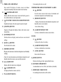
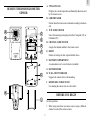
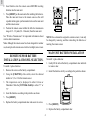
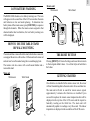
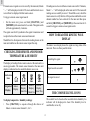
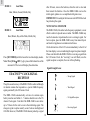
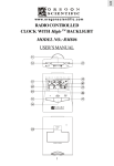
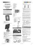
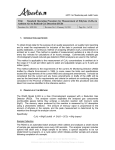
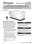
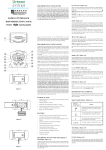
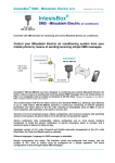
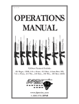
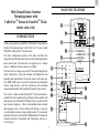
GB
MAIN UNIT FEATURES
Multi-Channel Indoor-Ooutdoor
Thermohygrometer with
Cable FreeTM Sensor & ExactSetTM Clock
C A B L E
F R E E
A
MODEL: RMR-136HG
B
INTRODUCTION
I
P M
C
C
Thank you for purchasing the RMR-136HG Multi-Channel IndoorOutdoor Thermohygrometer with Cable FreeTM sensor, model
THGR268, and ExactSetTM calendar clock.
M
EXACTSET
D
This basic configuration consists of the main unit that is the
temperature and calendar clock station, and the thermohygrometer
sensor remote unit. The main unit can support up to 3 remote
sensors. Additional remote sensors are available.
E
AM
RADIO
D
G
MEMORY
E
SET / MODE
F
DAILY
J
The main unit has a large easy-read LCD screen that displays the
indoor temperature, clock with calendar, and temperature and
humidity data transmitted by the remote sensor to the main unit.
The RMR-136HG also records the maximum and minimum
indoor temperatures, and the maximum and minimum
temperatures/humidity data transmitted from the remote sensor.
K
Model No. RMR136HG
L
M
TM
The clock is a radio-controlled ExactSet clock and includes a
calendar. The clock automatically synchronizes time and date with
radio signals received from the US Atomic Clock, one of the world’s
most accurate timepieces. Other clock/calendar features include
three-language choice for day-of-the-week display, a four-step
crescendo alarm and easy-change display modes. (To learn more
about the US Atomic Clock visit the US Department of Commerce's
National Institute of Standards and Technology website at:
www.nist.gov.)
N
Remote Therm-Hygro RMR136HG
Tested To Comply
With FCC Standards
FOR HOME OR OFFICE USE
O
P
Q
R
S
1
H
CONTROLLED
CHANNEL
GB
A. THREE-LINE LCD DISPLAY
For mounting the unit on a wall
Easy-read LCD display of remote sensor and indoor
temperature-humidity data and calendar clock functions
B. [
TEMPERATURE & RELATIVE HUMIDITY ALARM :
K. [ ▲ ] BUTTON
] BATTERY-LOW ICON
Sets the remote sensor alarm values of minimum and
maximum temperatures and humidity range
Indicates that the remote sensor or main unit battery power is
low and that batteries need replacement
L. [HIGH/LOW] BUTTON
C. [ ] US ATOMIC CLOCK SIGNAL RECEPTION ICON
- Displays the maximum and minimum temperatures and
humidity remote sensor alarms
Graphically displays the radio signal reception strength
D. [CHANNEL] BUTTON
-Saves alarm settings
Sequences through and displays indoor and remote sensor
channel data
M. [ALARM ON/OFF] BUTTON
Activates or disables the remote sensor alarms
E. [SET/MODE] BUTTON
CLOCK :
Switches between display modes and saves user-selected
settings
N. [ ▲ ] BUTTON
Advances the value of a setting
F. [DAILY ((.))] BUTTON
O. [ALARM ON/OFF] BUTTON
Sets the time for the alarm
Activates or disables the clock alarm
G. [MEMORY] BUTTON
P. [ ZONE ] BUTTON
- Displays the maximum or minimum temperature and humidity
readings
Selects the US time zone
- Clears the stored maximum and minimum temperature and
humidity data from remote sensor and the main unit
Q. [RESET] BUTTON
Returns all settings to their original default values
H. [((•))] ALARM ICON
R. BATTERY COMPARTMENT
Indicates that the alarm time is displayed
I. [
Accommodates two AA (UM-3) size batteries (included)
] ALARM-ON ICON
S. REMOVABLE TABLE STAND
Is displayed when the alarm is activate
For standing the main unit on a flat surface
J. WALL-MOUNT RECESS
2
GB
A. TWO-LINE LCD
REMOTE THERMOHYGROMETER
SENSOR
Displays the current temperature and humidity data measured
by the remote sensor
B. LED INDICATOR
Flashes when the remote sensor transmits a reading to the main
unit
A
B
C. °C/°F SLIDE SWITCH
C
Select between degrees displayed in either Centigrade (°C) or
Fahrenheit (°F)
E
D. CHANNEL SLIDE SWITCH
D
Assigns the channel number to the remote sensor
E. RESET
F
Returns all settings to their original default values
F. BATTERY COMPARTMENT
Accommodates two AA-size batteries (included)
G. BATTERY DOOR
H. WALL-MOUNT HOLDER
G
Supports the remote unit in wall-mounting
I. REMOVABLE TABLE STAND
For standing the remote unit on a flat surface
H
BEFORE YOU BEGIN
I
For best operation;
1. When using more than one remote sensor, assign a different
channel to each of the remote sensors.
3
GB
2. Insert batteries into the remote sensor BEFORE inserting
batteries into the main unit.
3. Press [RESET] on the main unit after installing the batteries.
Place the main unit close to the remote sensor as this will
expedite initial signal synchronization between the main unit
and the remote sensor.
4. Position the remote sensor within the effective transmission
range of 21 - 32 yards (20 - 30 meters) from the main unit.
See “Wireless Transmission” for important information about
wireless data transmission.
NOTE: Once a channel is assigned to a remote sensor, it can only
be changed by removing and then reinserting the batteries or
resetting the remote sensor.
Note: Although the remote sensor has been designed for outdoor
use, do not place the remote sensor in direct sunlight, rain or snow.
MAIN UNIT BATTERY INSTALLATION
REMOTE SENSOR BATTERY
INSTALLATION & CHANNEL SELECTION.
To install / replace batteries:
To install / replace batteries:
1. Gently lift the tab on the battery compartment door and slide
to remove door.
1. Remove the screws on the battery compartment.
2. Install the batteries strictly according to the polarities shown.
2. Using the [CHANNEL] slide switch, select the channel
number of 1, 2 or 3 for that remote sensor.
Model No. RMR136HG
3
The temperature can be displayed in either Celsius or
Fahrenheit. Slide the [°C/°F Slide Switch] to either “C” or
“F.”
Remote Therm-Hygro
FOR HOME OR OFFICE USE
4. Insert the batteries according to the polarities as shown.
5. Press [RESET].
6. Replace the battery compartment door and secure its screws.
3. Press [RESET].
4. Replace the battery compartment door.
4
GB
Remote unit
Wall-mount
LOW BATTERY WARNING
Table Stand
The RMR-136HG features a low battery warning icon. This icon
will appear on the second line of the LCD screen when the main
unit batteries are low and need replacing. To determine low
battery status of the remote sensor, press [CHANNEL] to sequence
through the channels. When the remote sensor assigned to that
channel number has low batteries, the low battery warning icon
will be displayed.
HOW TO USE THE TABLE STAND
OR WALL MOUNTING
The main unit has a removable table stand, which when connected,
can support the unit on a flat surface. Or the stand can be removed
and unit can be wall mounted using the recessed hanging hole.
THE RESET BUTTON
Pressing [RESET] will clear all settings and cause them to return
to their original default values. Use a blunt stylus to hold down
the button.
The remote unit also comes with a wall-mount holder and a
removable stand.
Main unit
Wall-mount
GETTING STARTED
Table Stand
Model
Once batteries are installed in the remote sensor unit, the sensor
will start transmitting data to the main unit in 40-second intervals.
36HG
No. RMR1
6HG
RMR13
Hygro To Comply
rds
ThermTested Standa
Remote
FCC USE
With
OR OFFICE
HOME
FOR
E E
F R
E
B L
C A
The main unit will start to search for remote sensor signals
approximately 3 minutes after batteries are installed. Upon
successful reception, the remote sensor temperature data will be
displayed on the top line of the LCD screen and the respective
humidity reading on the third line. The main unit will
automatically update its readings every 40-second. The indoor
temperature is displayed on the second line of the LCD screen.
E
P M C
D
M
AM
EXA
CTS
ET
RAD
IO
CHAN
CON
TRO
LLE
D
NEL
ORY
MEM
SET
E
/ MOD
DAILY
5
GB
If remote sensor signals are not received by the main unit, blanks
“ --- ” will be displayed on the LCD screen and the kinetic wave
icon will not be displayed for that remote sensor.
If readings are not received from a remote sensor after 15 minutes,
blanks “ --- ” will be displayed on the main unit LCD screen until
readings are successfully received. Should this occur, check the
remote sensor to verify that it is still in position and that the correct
channel number has been selected. On the main unit then press
and hold [CHANNEL] and [MEMORY] at the same time for 2seconds to trigger a remote sensor signal search.
To trigger a remote sensor signal search:
•
On the main unit, press and hold [CHANNEL] and
[MEMORY] at the same time for 2-seconds. The signal search
will take approximately 3-minutes.
The signal search will synchronize the signal transmission and
reception between the remote sensor and main unit.
HOW TO READ THE KINETIC WAVE
DISPLAY
Should there be discrepancies between the reading shown on the
main unit and that on the remote sensor repeat this step.
The kinetic wave display shows the signal receiving status of the
main unit. There are three possible forms:
CHECKING THE REMOTE AND INDOOR
TEMPERATURE & HUMIDITY
Searching for signal
The display of readings from a remote sensor or the main unit is a
one-step procedure. The remote sensor channel or the main unit
display is indicated in a box under the kinetic-wave icon.
Signal search successful
Kinetic-wave
Icon
Designated
Display
No signal received
Indoor
Display
Remote
Remote
Remote
Display
Display
Display
Channel One Channel Two Channel Three
THE COMFORT-LEVEL ICONS
The comfort level is based on the recorded relative humidity. An
indicator will be displayed or show if the humidity level is
comfortable, wet or dry.
To display temperature / humidity readings:
•
Press [CHANNEL] to sequence through the choices of
Indoor or remote sensor channel 1, 2 or 3.
6
GB
REMOTE SENSOR SCANNING
Humidity
Comfort-Level
Comfortable
Dry
The main unit can be set to automatically scan and display data
readings from the remote sensor as well as indoor readings. When
the remote-sensor mode is active, the main unit LCD scree will
display the readings from one channel for approximately 4seconds and then proceed to display the next channel data.
Wet
TEMPERATURE AND HUMIDITY
TREND INDICATOR ICONS
To activate the remote-sensor scanning mode:
•
The temperature-trend and humidity-trend indicator arrow icons
show the trends based on collected readings.
•
Press any button.
MAXIMUM AND MINIMUM
TEMPERATURE AND HUMIDITY
Arrow
Indicator
Temperature
Trend
Press and hold [CHANNEL] for 2-seconds.
To deactivate the remote-sensor scanning mode:
Rising
Steady
Falling
The maximum and minimum recorded temperature and humidity
readings will automatically be stored in the memory.
To display the maximum and minimum display memory:
1. Press [CHANNEL] to select the channel to be checked.
Arrow
Indicator
Humidity
Trend
Rising
Steady
2. Press [MEMORY] once to display the maximum (MAX)
temperature and then again to display the minimum (MIN)
temperature. The identifiers of “MAX” and “MIN” will be
displayed as appropriate.
Falling
To clear the memory:
NOTE: If the temperature exceeds or fall below the temperature
measuring range of the main unit or the remote sensor the main
unit LCD screen display will show “HHH” or “LLL”. See
“Specifications” for the temperature measuring ranges.
•
Press and hold [MEMORY] for 2-seconds.
After clearing the memory, the maximum and minimum
temperatures and humidity levels will be the same as current until
new data readings are recorded.
7
GB
3. Repeat steps 1 and 2 to set the maximum humidity setting and
the minimum temperature and humidity settings.
HOW TO USE CHANNEL-1
TEMPERATURE/HUMIDITY ALARM
4. When finished, press [HI/LO] to set another limit or wait 16seconds and the unit will automatically return to the normal
display mode. The appropriate HI, LO or both indicators will
be displayed indicating the alarm status.
Maximum and minimum temperature and humidity limits can be
set for remote sensor channel-1 so that an alarm sounds when the
user-selected limits are exceeded.
When the alarm activates the main unit LCD screen display will
automatically switch to channel-1 if in another remote sensor
channel mode and will flash. The alarm will sound for one minute
unless disabled.
The maximum and minimum temperatures and humidity are
sequentially displayed by pressing [HIGH/LOW].
The High-Low displays are as follows:
Respective Display
Press any key to momentarily stop the alarm. The alarm will
automatically reactivate again if the limit continues to exceed the
set limits.
Press [HI/LO] X 1
Displays the HIGH temperature
NOTE: Temperature Range:
Press [HI/LO] X 2
Displays the HIGH humidity
Press [HI/LO] X 3
Displays LOW temperature
Press [HI/LO] X 4
Displays LOW humidity
Sequence
The temperature range is from -58°F to 158°F (-50°C to 70°C).
When setting the limits for the first time, the low/minimum
limit will start at -58°F (-50°C) and the high/maximum limit
at 158°F (+70°C). After the initial setting, the high/low limits
will start from the temperatures as last selected.
NOTE: Humidity Range:
To set the maximum or minimum temperatures or humidity
level alarms:
The humidity range is from 2% to 98%. When setting the lim
its for the first time, the low/minimum limit will start at 2%
and the high/ maximum limit at 98%. After the initial setting,
the limits will start from the humidity levels as last selected.
1. Press [HI/LO]. Remote sensor channel-1 will be displayed.
2. Press [ ▲ ] to set the temperature or humidity limits. Each
press will increase the setting in increments of one (1) degree
or humidity percentage. Press and hold [ ▲ ] for rapidscrolling increments of five (5) degrees or humidity
percentage.
NOTE: Alarm Sounding:
If a set limit is exceeded a second time while the alarm is
sounding, the alarm will complete its first 1-minute cycle
before sounding for another 1-minute cycle indicating that a
limit has been surpassed a second time.
8
GB
TRANSMISSION INTERFERENCE
To turn the alarm off:
1. While the alarm is sounding, press [HI/LO].
2. Then press [ALARM ON/OFF].
3. The alarm has now been disabled and will not sound again until
reactivated.
To temporarily deactivate a sounding alarm:
1. Press any button and the alarm will be temporarily deactivated.
The alarm will sound again when a set limit is exceeded.
INTERRUPTED SIGNALS
If the display for a particular remote sensor goes blank on the main
unit LCD screen, press [CHANNEL] and [MEMORY] on the main
unit at the same time for about 2-seconds to trigger a signal search
between the main unit and the remote sensor.
Signals from household devices, such as door bells, home
security systems and entry controls, may interfere with those
of the RMR-136HG and result in temporarily reception
failure. This is normal and will not affect the general
performance of the product. The transmission and reception
of temperature and humidity data readings will resume once
the interference ends.
The success of wireless data transmission may vary and is
directly related to where the remote sensor is placed and the
environmental factors of that location. Should there be
difficulty in data transmissions, verify:
1. The low battery warning icon is not displayed for either the
main unit or the remote sensor. Replace batteries as
necessary.
If the search does not reactive the signal reception, verify:
1. The remote sensor is still in position.
2. The remote sensor is within the effective transmission range
of 21 - 32 yards from the main unit.
2. The low battery warning icon is not displayed for the main unit or
the remote sensor. Replace batteries as necessary.
3. That there are no obstacle (like a transmission tower) or
environmental reason (such as a steep hill) that is causing
the interference or blockage between the main unit and the
remote sensor.
3. The remote sensor is within the effective transmission range of 21
to 32 yards from the main unit, and that the transmission path is
clear of obstacles and interference. Shorten the distance if
necessary.
NOTE: When the temperature falls below freezing point, the batteries
in the remote sensor will freeze lowering the voltage supply
and the effective range.
9
If the difficulty continues, reposition the remote sensor to a
different location and/or closer to the main unit.
CALENDAR CLOCK DISPLAY MODES
The RMR136HG has two different time display modes:
GB
MODE 1:
Local Time
after 48 hours, remove the batteries, allow the unit to clear and
then reinsert the batteries. Once the RMR-136HG receives the
initial signal, updates are accomplished with greater ease.
Hour, Minute, Second, Month, Day
IMPORTANT: Do not adjust the time zone until AFTER the clock
has picked up the signal.
NOTE: SIGNAL STRENGTH
MODE 2:
The RMR-136HG, like other radio frequency equipment, is most
effective when it is placed near a window. The RMR-136HG may
need to be moved or repositioned to receive a stronger signal. For
best reception, place the RMR-136HG away from metal objects
and electrical appliances to minimize interference.
Local Time
Hour, Minute, Day-of-the-Week, Month, Day
On the bottom line of the LCD screen immediately to the left of
the time display, is an icon indicating the signal reception strength.
Please note that while the RMR-136HG is receiving a signal from
the US Atomic Clock, the “receiving” icon will flash; once the
signal reception is complete, the icon will stop flashing.
Press [SET/MODE] switch between the two time display modes.
Note: When [24 hr OFF / ((.))] is pressed the bottom line of the
main unit LCD screen will display the alarm time.
Signal Strength Icons:
EXACTSETTM CLOCK SIGNAL
RECEPTION
- Strong Signal
The split-second accuracy of the RMR-136HG is achieved through
its internal antenna that responds to a special 60kHz frequency
signal generated by the US Atomic Clock.
- Weak Signal
The RMR-136HG automatically activates its antenna upon
battery insertion and within 3 - 7 minutes should receive the US
Atomic Clock signal. Note that if the RMR-136HG is new allow
up to 72 hours for the unit to receive the initializing signal. The
strongest signal reception usually occurs between midnight and
4:00 AM. However, if the RMR-136HG has not picked up a signal
- No Signal Reception
- Receiving Signal
10
GB
NOTE: When setting the hour, be aware of the AM/PM
designations.
4. When the hour has been selected, press [((.))] again and
the minutes digits of the alarm time will begin to flash.
5. Press [ ] to advance the minute selection inincrements of
one minute, or press and hold for rapid advancement.
6. When the alarm time is set, press [((.))]. The alarm will
automatically activate itself. The active alarm status is
indicated by the bell icon just above the ((.)) symbol.
SELECTING THE TIME ZONE
CAUTION: Do not press and hold [ZONE] for more than 3seconds. Doing so will deactivate the automatic time signal
reception capability. If the automatic signal reception is disabled,
the signal strength icon will not be displayed. To reactivate the
automatic signal reception, press [ ] for three seconds
On the bottom line of the LCD screen there is a map outlining the
United States divided into the four US time zones.
1. Press and release [ZONE] to sequentially advance through the
time zones from west to east.
ACTIVATING/DISABLING
THE CLOCK ALARM
2. The selected time zone will be darkened on the map.
To see the time in a different time zone:
To active the daily alarm, press [AL ON/OFF]. When the alarm
is active, a bell icon will appear in the lower left corner of the
LCD screen. If the alarm is not active, there will be no bell icon.
1. Press and release [ZONE] until the desired time zone is
darkened on the map icon. The time will automatically adjust
to that time zone.
When the alarm sounds there are two ways to turn it off:
1
SETTING THE CLOCK ALARM
Press [((.))]. The alarm will remain active but will not sound
again for 24-hours.
2. Press [AL ON/OFF]. The alarm function is disabled and will
not sound again until reactivated.
1. Press [((.))]. The ((.)) symbol will appear on the bottom line
of the LCD screen, lower right hand corner. The alarm time
will also be displayed on the same line of the LCD screen.
IMPORTANT: The RMR-136HG has an automatic snooze
feature. If the alarm is not disabled by either option 1 or 2 above,
the alarm will automatically go into “snooze” once, sound again in
8 minutes and then temporarily turn itself off for 24-hours.
2. Press and hold [((.))] until the hour digits of the alarm time
begin to flash.
3. Press [ ] to advance the hour selection in increments of
one hour, or press and hold for rapid advancement.
11
GB
4. When the last setting has been made, press [MODE] to exit
the setting mode and return to the normal time display mode.
SELECTING THE DAY-OF-THE-WEEK
LANGUAGE DISPLAY
IMPORTANT: As soon as any manual setting changes are made
to the clock, the low signal strength icon will be displayed
indicating that the clock is now running on manual settings
instead of signals from the US Atomic Clock. In manual mode,
it is very unlikely that the RMR-136HG will receive signals
from the US Atomic Clock. To reactivate signal reception, press
[RESET] or remove the batteries, allow the unit to clear all
settings and then reinsert the batteries.
The RMR-136HG has three language choices for the day-of-theweek display: English (E), Spanish (S) and French (F). To select
the display language:
1. Press [MODE] until the hour display begins to flash.
2. Press [MODE] five (5) more times and a single letter (E, S, or
F) will be displayed on the LCD screen next to the time
display.
3. Press [
] to advance and sequence through the language
choices.
4. When the language is selected, press [MODE] one time to
exit the language setting mode and to return to normal time
display mode.
CUSTOMER ASSISTANCE
Should you have questions or require additional information
about this product, please contact our Customer Service
Department at 800-853-8883 or via email at:
[email protected]
MANUALLY SETTING THE CLOCK
The RMR-136HG is an ExactSetTM clock and does not need to
be set manually. However, instructions to set the clock manually
are included and follow:
Please also visit our website at: www.oregonscientific.com
1. Press and hold [MODE]. The hour digits of the time display
will begin to flash.
Oregon Scientific warrants this product to be free of manufacturing defects for 90 days from date of retail purchase. Defective
products should be returned to the place of retail purchase.
2. While the hour digits are flashing, press [
desired hour is reached.
WARRANTY
] until the
This warranty does not cover product subjected to tampering,
misuse, abuse or accidental damage.
NOTE: When setting the hours, be aware of the AM/PM
designations.
3. When the hour is set, press [MODE] again and the minutes
segment of the time display will begin to flash. Repeat the
above steps to set the minutes, year, month, date and day-ofthe-week.
PRECAUTIONS
This product has been designed and manufactured to provide you
with year of service if it is carefully handled. Please follow these
few precautions:
12
GB
1. Do not immerse the main unit or remote sensor in water.
Remote thermohygrometer sensor:
2. Do not clean the product with abrasive or corrosive materials.
They may scratch the plastic parts and corrode the electronic
circuit.
Proposed operating range:
4.0° F to 140.0°F
Temperature resolution:
0.2°F (0.1° C)
Temperature compensation:
14.0° F to 140.0° F
(-20.0° C to 60.0°C)
3. Do not subject the product to excessive force, shock, dust,
temperature or humidity which may result in malfunction,
shorter electronic life span, damaged battery and distorted parts.
(-10.0° C to 60.0° C)
4. Do not tamper with the product's internal components. Doing
so will invalidate the warranty on the unit and may cause unnecessary damage. This product contains no user-serviceable
parts.
Relative humidity operating range: 25% RH to 90% RH
5. Only use fresh batteries as specified in the user's manual. Do
not mix new and old batteries as the old ones may leak.
RF transmission range:
6. Always read the user's manual thoroughly before operating the
unit
Temperature sensing cycle:
RF transmission frequency:
433 MHz
Number of remote sensors:
Maximum of 3
Maximum 32.5 yards
(30 meters)
approximately 40 seconds
Radio Controlled Clock
SPECIFICATIONS
Main time set and synchronized by Radio Signal WWVB for
USA
Temperature Measurement
12-Hr display hh/mm/ss format
Main unit:
Proposed operating range:
Date format in Month/day
23.0° F to 122.0°F
Day-of-the-week language:
(- 5.0° C to 50.0°C)
Temperature resolution:
0.2°F (0.1° C)
Temperature compensation:
14.0° F to 140.0° F
Choice of English, Spanish
and French
Four time zone with date and day
2-Minute crescendo alarm
(-10.0° C to 60.0° C)
Power
Main unit:
Relative humidity operating range: 25% RH to 90% RH
13
2 pcs ”AA” (UM-3)1.5V
alkaline battery
(included)
GB
Remote sensor:
2 pcs “AA” (UM-3)
1.5V alkaline battery
(included)
WARNING: Changes or modifications to this unit not expressly
approved by the party responsible for compliance could void the
user’s authority to operate the equipment.
Weight
Main unit:
5.77 oz (without batteries)
Remote sensing unit :
2.82 oz (without batteries)
NOTE: This equipment has been tested and found to comply with
the limits for a Class B digital device, pursuant to Part 15 of the
FCC Rules. These limits are designed to provide reasonable
protection against harmful interference in a residential installation.
This equipment generates, uses and can radiate radio frequency
energy and, if not installed and used in accordance with the
instructions, may cause harmful interference to radio
communications.
165 g (without batteries)
80.5 g (without batteries)
Dimension
Main unit:
5.68”(L) x 3.36”(W) x
However, there is no guarantee that interference will not occur in
a particular installation. This equipment does cause harmful
interference to radio or television reception, which can be
determined by turning the equipment off and on, the user is
encouraged to correct the interference by one or more of the
following measures:
- Reorient or relocate the RMR-136HG.
- Increase the separation between the affected equipment and
the RMR-136HG.
- Consult an experienced radio/television technican for
assistance.
0.98”(T)
(142(L) x 84(W) x
24.5(T) mm)
Remote sensing unit:
4.2”(L) x 2.8”(W) x
0.84”(T)
(105(L) x 70(W) x
21(T) mm)
NOTE ON COMPLIANCE
This product complies to standards and specifications of BZT, FCC
and article number 334 of PTT.
Product Name
: Remote Thermo-Hygro
Model Name
: RMR136HG
This device complies with Part 15 of the FCC Rules. Operation is
subject to the following two conditions: (1) This device may not
cause harmful interference, and (2) This device must accept any
interference received, including interference that may cause
undesired operation.
Responsible Party : IDT (USA) Mr. David Childers 19861 SW
95 th Place Tualatin, Oregon 97062, U.S.A.
Tel: 503-639-8883
14
GB
CAUTION
- The contents of this manual is subject to change without
notice.
- Due to printing limitations, the displays shown in this manual
may differ from the actual product displays.
- The manufacturer and its suppliers hold no responsibility to
you or any other claim arising by using this product.
- The contents of this manual may not be reproduced without
permission of the manufacturer.
15
086-002229-01