1
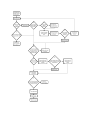
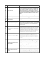
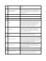
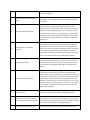
Cell Counter Flowchart Description # Text box Explanation or comment 1 Begin Start troubleshooting process for a work-‐order on a Cell or Coulter Counter. 2 Is the device free from debris? Check exterior of device for any dirt, dust or other debris. 3 Clean exterior of device Often parts appear broken or malfunctioning when they are simply not clean. It is most important to ensure that all openings, hinges and connecting or interacting pieces are clean. See BTA skills for Cleaning. 4 Is the device free of external damages? Check for dents, scratches, and other major damage to the outside of the device. In particular, look to see if there is evidence of whether or not the device has been dropped. 5 Assess severity of damage Damage to the exterior of the device can indicate the presence of internal damage and offer insight as to where inside the casing to begin looking for damage. If damage to the exterior is minimal it can likely be ignored. If too severe, it is possible the device will not function at all. 6 Repair as applicable Using appropriate BTA skills on Casing, Attachment and Cleaning, repair scratches, dents, etc as possible. 7 Make sure you have all necessary reagents, solutions and trouble-‐ shooting tools It is a possible user error that the device is simply missing key components that are involved in its use but are not inherently present within the device. If possible, check the user manual or any other type of documentation, to determine whether or not the appropriate auxiliary components are being used, and being used properly. 8 Is the device on a clean, sturdy, level surface? The measurements that this device makes are minute and precision is of the utmost importance. A sturdy and level surface is necessary to ensure accurate results. 9 Move device to a clean, sturdy, level surface A clean, sturdy, level surface is one that does not wobble visibly or tangibly when the device is operated, is not on a slant, and is wiped free from dust and debris. 10 Is the atmospheric temperature between 16-‐34 C? Use a thermometer to check. 16-‐34 C is the optimal operating temperature for both the electronic and liquid components of the device. 11 Move device to a room with appropriate temperature range, or Execute as possible. adjust temperature of current room 12 Is device near any EM field inducing device? EM (Electro Magnetic) fields are generated by very powerful devices such as x-‐ray machines, scanners, anything with a radar, etc. These fields can interfere with the circuitry and the accuracy of device measurements. 13 Move device away from strong EM devices The simplest solution to this problem is to move the device, which, though bulky, is likely much more portable than any of the EM field generating devices. 14 Power device on Press the “on” or “power” button or switch. 15 Does the device turn on? Look for visible signs that the device has turned on. Indicators could be sounds of pieces within the device loading up and moving, a screen lighting up, an LED (typically green) illuminating, etc. 16 Troubleshoot power supply Consult BTA skills on Power Supply and Power Supply flowchart for assistance. 17 Open device casing. Check for loose, worn-‐out wires and corrupt circuit boards. Inspect the way that the casing is put together and use BTA skills for Casing to determine the order that the pieces need to be removed. Inspect for worn-‐out, frayed, rusted, etc wires. Use BTA skills Electrical Simple to repair as necessary. Does the screen respond to the appropriate input? Press the keypad or screen (if touchscreen) or appropriate buttons to prepare device as if to run a cycle. Determine whether or not the screen is responding as it should. Possible examples of incorrect screen inputs include moving to the incorrect menu (one that does not correspond to the input pressed), a frozen screen, an error message, etc. 19 Set up the device to run as normal Set all system modes and settings as if a sample were to be run normally. This verifies that the device is being used properly and that, as troubleshooting continues, user error is not a factor. 20 Does the screen show an error message? Error messages are fairly obvious as they are accompanied by the words “caution”, “error”, “warning”, etc. Error messages serve as an internal way for the device to give a better indication of which area of the device is malfunctioning. 21 Is it possible to follow on-‐screen instructions to troubleshoot? With higher-‐level and more modern models, the device may have software designed to guide the troubleshooting process. 22 Follow on-‐screen troubleshooting instructions If it is built into the software, the device will guide through the steps to take to approach problems associated with the 18 malfunctioning part of the machine. 23 Run control cycle Control cycles are run with deionized water. The system is set to run as it would normally with a sample, but only deionized water is used for the “sample” and each of the reagents. This enables the observation of all of the moving parts within the device and also shows whether or not the device is functioning mechanically, even if it does not display that proper results or values. 24 Follow PM procedure See accompanied PM (Preventative Maintenance) procedure. 25 Device is ready Device should be functioning properly 26 Run a test cycle A test cycle is the same as a control cycle. See explanation for Box 23. Does the test run to completion? The test cycle has run to completion if the cycle drew the water through all of the appropriate channels, was not stopped along the way, produced no error messages, and displayed results at the end. Does the probe or aperture appear damaged? The sample probe is a thin metal rod with a small opening, like a needle, that is open to the exterior of the device. It is used to draw up the sample into the device to initiate a run cycle. A damaged probe is likely to be bent or chipped. The aperture is inside the device and is sized on the order of millimeters. A damaged aperture is likely to be cracked or corroded. Is the probe or aperture clogged? As the probe serves to draw fluid up and into the device and as the aperture facilitates fluid flow through the device, it is possible that debris may build up causing either to clog and thereby inhibit the analysis of the sample. See BTA Skills on Blockages. 30 Does the probe rest in its neutral home position? The neutral home position of the probe should be marked, either by a tick mark or a line on the casing, or on the probe itself. If this mark exists, make sure that the probe is aligned properly so that it is functioning at maximum capacity. If the device does not have a marking to indicate the neutral home position, place an empty sample collection container in the appropriate position as if the device were to run a test, and verify that the probe is in a position so that it can draw up the entirety of the contents of the sample collection container. 31 Manually adjust probe to home position 27 28 29 It is possible that the probe may be adjusted or calibrated via instructions and a process through the device software on the screen. See BTA skills on Calibration. If this is the case, follow these instructions. Otherwise, it is likely that the probe is held in position by a series of set screws that can be manually adjusted. 32 Does the device output the appropriate values? Look at the display screen to verify that the software of the machine is functioning. Specific values vary by model and brand; the main objective of this step is to make sure that the electronic components of the device are functional, if not necessarily accurate. 33 Go to box 49 34 Problem is a user or sample error Each of the components of the device are functioning properly. 35 Replace probe, if possible If not possible, the device cannot function. Unclog Probe may be unclogged simply by soaking and washing with warm, deionized water. If necessary, it may also be unclogged using a small needle or brush, depending on the size of the probe and its opening. Aperture can be unclogged using a small needle or brush, but must be done gently so as not to damage the device. See BTA skills on Blockages. 37 Open casing If it hasn’t been done yet, open the casing as described in step 16. Opening the casing not only allows for inspection of the electronic elements, but also provides an opportunity to inspect the basic physical and mechanical workings of the device. See BTA skills on Casing. 38 Can fluid flow through tubing easily? Indicators of fluid not flowing easily are bubbles, leaks or the machine stopping. See BTA skills on Blockages. Check for clogged tubing Tubing may be clogged simply by having folded in on itself, or having been pinched to prevent flow. It may also be clogged by debris or build-‐up. Any cause of clogging should be removed, if possible, by removing and rinsing the tubing or using a small brush if the clog is near the opening. If necessary, tubing can also be replaced. See BTA skills on Blockages. 40 Are there any leaks? Leaks can stem from defective tubing, broken valves, broken reservoirs, or any of the connections between these parts. Clamps are also a suitable solution to this problem. See BTA skills on Leaking and Clamps. 41 Skip to box 45 Check valve functionality An alternative and more specific source of leaks may be the valves. Valves or valve parts that wear down (like O-‐rings) can wear down and lose their water-‐tight properties. 36 39 42 Check connections to waste system, reservoirs, reagent supplies, etc Leaks will often stem not from a particular part, but the places where parts intersect and interact. These can be replaced, tightened, or patched up accordingly. See BTA Skills on Connections and Seals. Check piston pressure and seals Not every model of the device will contain pistons, however many do, and the purpose of the pistons is to draw up and transport solution to different parts and processes within the device. It is imperative that the piston is actually drawing up liquid. If not, the seals can be adjusted and tightened. If the problem persists, the piston probably needs to be replaced. See BTA skills on Seals and Motors. Close casing When opening casing, be sure to keep track of all panels and screws. Close the casing in the exact reverse of opening the casing. See BTA skills on Casing. 46 Do all moving pieces operate smoothly? As the control/test cycle runs, verify that pieces that are supposed to be moving, are doing so properly. The device can break down is via the wear and tear of basic mechanical components. Although it cannot be predicted which pieces exactly are of critical loading, visually inspecting the system as it runs can verify whether or not there is anything grinding, catching, in need of lubrication, broken, blocked, caught, etc. See BTA skills on Mechanical and Motors. 47 Are all pieces aligned properly? It is possible, especially if there is any evidence of external damage or dents, the device is not functioning properly because the moving parts are misaligned. Align any misaligned pieces Most pieces or parts are held in place by set screws or hex screws that can be loosened to allow for the adjustment of the piece. As a general rule, all interacting parts with a round geometry should align concentrically and all translational parts should move in straight, perpendicular lines. Do the temperatures of the baths match the indication on the attached cables? For most models, the desired temperature range for the baths or reservoirs of each of the liquids or reagents used in a run cycle will be marked on the small cable connecting the hot plate (or similar mechanism) that maintains the temperature, to the power supply. Use a thermometer to verify that the temperature of the specific liquid falls within the appropriate range. However, if the temperature does not match properly, very few models have associated processes to fix the problem. 43 44 45 48 49 50 Empty, clean and refill baths Reagents in device should be discarded appropriately. The device can be cleaned using deionized water only, and running a test or, if the model has one, a cleaning cycle. Baths can then be refilled. It is possible that temperature, and even general device running issues stem from build-‐up in the tubing, reservoirs and baths. Check for broken gears, bands or parts As the control cycle runs, visually check for any mechanical load bearing or linking parts that may have broken. Fix these as possible. Check for blocked pathways As parts move within the device, it is possible, especially if there is evidence of external damage, that pieces or parts within the device have shifted or been knocked out of place. In addition to throwing off alignment, this can manifest itself as the blockage of the pathway of a moving part. Any blockages should be cleared, and if any of the blockages involve broken or misplaced parts, these should be reattached or replaced as appropriate. Are the motors functioning properly? Although not the case for all models of the device, many power the movement and coordination of internal parts and pieces with motors. To ensure that the device is working properly, check to see if the motors are functioning properly. A properly functioning motor will make a small, continuous whirring sound when operating, and will lead to the motion of another piece or part within the device. See BTA skills on Motors. Troubleshoot motors Motors commonly fail in two ways: mechanically and electrically. Motors can wear out, or jam or their rotor may be blocked. Electrically, the wiring in and around the motor can be checked as well. See BTA skills on Motors and Electrical Simple. 55 Is internal lamp functional? In addition to a resistance or voltage-‐based aperture measurement, many models, especially the more modern models, have a lamp or light device of some kind that is used in conjunction with photosensors to take various measurements from a sample. To check if the lamp is functional, first verify whether or not the lamp is “on” when the device is “on.” It may also be possible to use the software menus to turn the lamp on or off. A lamp is deemed functional if it emits light under the appropriate conditions. 56 Remove bulb and check voltage drop of socket Use potentiometer to verify that the lamp component is receiving current. See BTA skills for Lighting/Indicators. 57 Does voltage drop across socket correspond to bulb specifications? If the lamp has a bulb component, it is likely to have printed specifications as to the current and voltage that correspond to the optimal functionality of the bulb. Use a multimeter to check the voltage. See BTA skills for Lighting/Indicators. Check wires and connections to The simplest way that the lamp component may fail, other 51 52 53 54 58 socket than a broken or worn out bulb, is in the immediate circuitry connecting the lamp to the power supply. See BTA skills for Lighting/Indicators. Replace bulb If the socket is receiving the appropriate current and voltage, the problem lies within the bulb, which should be replaced. See BTA skills for Lighting/Indicators. 60 Verify lamp alignment More modern models typically have software menus to guide through the lamp alignment process. If not, the lamp can be more roughly aligned by verifying that the accompanying photosensors are responding appropriately. As with many of the moving parts of the device, the lamp can be adjusted manually after loosening the appropriate set screws. 61 Are all internal resistors and driving electrodes receiving current? Use a multimeter to check that there is a voltage drop across and current is running through the key electric components. 62 Device is beyond repair 63 Clean electrodes Electrodes can be cleaned with deionized water. See BTA skills on Switches and Connectors. 64 Close casing When opening casing, be sure to keep track of all panels and screws. Close the casing in the exact reverse of opening the casing. See BTA skills on Casing. 65 Device is ready 59