1
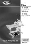
USER’S
MANUAL
KM-250/KM-350 Series
High-Speed, 1-Needle, Drop-Feed
Automatic Thread Trimmer
High-Speed, 1-Needle, Drop-Feed,
Needle-Feed Automatic Thread
Trimmer
Keystone Sewing Machine Company, Inc.
833 N 2nd Street, Philadelphia, PA 19123 USA
215/922.6900
[email protected]
www.keysew.com
SUNSTAR MACHINERY CO., LTD.
KM-506/KM-530 Series
High-Speed 1-Needle, Drop-Feed
Knife-Attached Automatic Thread
Trimmer
High-Speed, 1-Needle, Drop-Feed,
Needle-Feed Knife-Attached
Automatic Thread Trimmer
1) For use with maximum ease,
please be sure to read this manual
thoroughly before use.
2) Keep this manual for reference in
case of machine malfunction or
breakdown.
MME-070426
lity
a
u
tQ
Besst Pricevice
Be st Ser
Be
1. Thank you for purchasing our product. Based on the rich expertise and
experience accumulated in industrial sewing machine production, SUNSTAR
will manufacture industrial sewing machines, which deliver more diverse
functions, high performance, powerful operation, enhanced durability, and
more sophisticated design to meet a number of user’s needs.
2. Please read this user’s manual thoroughly before using the machine. Make
sure to properly use the machine to enjoy its full performance.
3. The specifications of the machine are subject to change, aimed to enhance
product performance, without prior notice.
4. This product is designed, manufactured, and sold as an industrial sewing
machine. It should not be used for other than industrial purpose.
R
SUNSTAR MACHINERY CO., LTD.
Keystone Sewing Machine Company, Inc.
Contents
Safety Rules for Machines .....................................................................................................................................4
1. Specifications
1) Automatic trimmer .......................................................................................................................................................8
2) Servo motor ..................................................................................................................................................................8
3) 470 motor .....................................................................................................................................................................9
4) 470 motor controller.....................................................................................................................................................9
5) Peripheral automation devices (optional)....................................................................................................................9
2. Installation
1) Machine head .............................................................................................................................................................10
2) Chip discharge plate ...................................................................................................................................................10
3) Resistance box for knee-lifting solenoid ...................................................................................................................11
4) Lubrication .................................................................................................................................................................11
5) Belt tension adjustment..............................................................................................................................................12
6) Program unit...............................................................................................................................................................12
7) Belt cover ...................................................................................................................................................................13
8) Location detector assembly and adjustment ............................................................................................................14
9) Location adjustment of location detector ..................................................................................................................14
10) Check for stop position of sewing machine ............................................................................................................15
11) Back tack button.......................................................................................................................................................15
3. Control and Adjustment of the Sewing Machine
1) Needle insertion .........................................................................................................................................................16
2) Needle bar adjustment ...............................................................................................................................................16
3) Timing adjustment of needle and hook .....................................................................................................................16
4) Lubrication adjustment of thread take-up lever ........................................................................................................16
5) Lubrication adjustment of hook.................................................................................................................................17
6) Inserting lower thread and tension adjustment .........................................................................................................18
7) Routing upper thread..................................................................................................................................................18
8) Upper thread adjustment ............................................................................................................................................19
9) Height and tension adjustment of presser foot..........................................................................................................20
10) Adjustment of automatic knee-lifter .......................................................................................................................20
11) Stitch length adjustment...........................................................................................................................................21
12) Height and inclination adjustment of feed dog .......................................................................................................21
13) Feed cam adjustment ...............................................................................................................................................22
14) Adjustment of needle movement.............................................................................................................................22
15) Timing adjustment of trimmer.................................................................................................................................23
16) Tension adjustment of fixed blade...........................................................................................................................24
17) Replacement of movable knife ................................................................................................................................24
18) Replacement of fixed blade .....................................................................................................................................24
19) Adjustment of bobbin catcher .................................................................................................................................24
20) Wiper adjustment .....................................................................................................................................................25
21) Knife adjustment ......................................................................................................................................................26
22) Use of chip discharge guide and auxiliary needle plate .........................................................................................27
23) Change of cutting width...........................................................................................................................................27
4. Cause of Troubles and Troubleshooting
1) Sewing machine troubleshooting ..............................................................................................................................29
Keystone Sewing Machine Company, Inc.
Safety rules for machines
Safety labels in the manual are categorized into danger, warning and caution.
Failure to follow the safety rules may result in physical injuries or mechanical damages.
The safety labels and symbols are defined as follows.
[ The meaning of the safety marks ]
Danger
Instructions here shall be observed strictly.
Otherwise, the user will be killed or suffer severe physical injuries.
Warning
Instructions here must be observed, or the user could suffer fatal or severe physical injuries.
Caution
Instructions here should be observed, or the user could face physical injuries or
mechanical damages
[ The meaning of marks ]
This mark means a‘must-not.’
This mark means a‘must’for safety.
This mark means that an electric shock may be caused if the
instruction is not followed properly.
4
Keystone Sewing Machine Company, Inc.
1-1) Machine
mobilization
Danger
1-2) Machine
installation
Caution
Only personnel with a full understanding of the safety rules should move the machines.
The following directions must be observed when delivering the machines.
ⓐ At least two or more people should move the machine.
ⓑ Before delivering the machine, thoroughly wipe off the oil on the machine to
prevent accidents.
Physical damages such as functional difficulties or breakdowns may occur
depending on installation conditions of the machines. Be sure to heed the following
conditions.
ⓐ Remove the packing from top to bottom. Watch out for nails on the wooden box.
ⓑ Install a climate controller and clean it regularly to prevent dust and moisture buildup from contaminating and corroding the machines.
ⓒ Keep the machines away from direct sunlight.
ⓓ Keep a minimum distance of 50cm between the machine at both sides and
backside and the wall to secure sufficient space for repair.
ⓔ Do not operate the machine near areas with danger of explosion. Refrain from
running the machine in the vicinity of risky places, e.g., where a large quantity of
aerosol-spraying products or oxygen are handled, unless specific guarantees are
given otherwise for the operation of the machine to prevent explosion at such
places.
ⓕ The user should install an illuminator in the work area for the machine does not
come supplied with any lighting apparatus due to the specific features of the
machine.
[Note] Details of the machine installation are laid out in No. 2 Installation.
1-3) Troubleshooting When the machine is in need of repair, only our authorized service technicians must
handle it.
Danger
ⓐ Before cleaning and repairing the machine, shut off the power supply and wait four
minutes for the machine to discharge completely.
ⓑ No part of the machine or specifications may be modified without prior consultation
with our company. Any such modification could risk safe operation of the machine.
ⓒ In case of repair, replace only with standard OEM parts from SunStar.
ⓓ After repair, put safety covers back on the machine.
5
Keystone Sewing Machine Company, Inc.
1-4) Machine
operation
Caution
KM-250 Series are intended to be used for industrial purposes for sewing textiles and
other similar materials. Carefully study the following instructions before operating the
machine.
ⓐ Read the manual thoroughly and understand the instructions fully before use.
ⓑ Put on proper safety garments.
ⓒ While the machine is in motion, keep your hands or any part of your body away from
moving parts, e.g., needle, hook, thread take-up spring and pulley, etc.
ⓓ Do not remove any form of safety covers while the machine is in use.
ⓔ Be sure to connect the ground (earth) wire.
ⓕ Before opening electric boxes such as the control box, shut down the power supply
and make sure the power switch is in“off”mode.
ⓖ Stop the machine before threading the needle or checking after sewing work is
finished.
ⓗ Never turn the power switch on with the pedal down.
ⓘ Do not use the machine if the cooling fan is clogged. Clean the air filter embedded in
the control box at least once a week.
ⓙ Keep the machine away from strong electromagnetic fields such as high-frequency
welding machines.
Caution
1-5) Safety device
Caution
Always start the machine with safety covers in place
since fingers or hands could be injured or cut off by the
belt. Turn off the power switch when conducting a
regular check on the machine.
ⓐ Safety label: Safety instructions for machine operations
ⓑ Thread take-up spring cover : A device designed to prevent the human body from
coming in contact with the thread take-up spring
ⓒ Belt cover: A device intended to avoid potential risks of getting hands, feet or clothes
jammed by the belt
ⓓ Finger guard: A device built to keep fingers away from the needle
ⓑ
ⓐ
ⓒ
ⓓ
6
Keystone Sewing Machine Company, Inc.
1-6) Location of
caution mark
CAUTION
경 고
“Caution”is attached on the machine for safety. Read the directions of“caution”
carefully before running the machine.
[Location of caution mark]
Do not operate without finger guard and
safety devices. Before threading, changing
bobbin and needle, cleaning etc. switch off
main switch.
손가락 보호대와 안전장치 없이 작동하지
마십시오.
실, 보빈, 바늘교환시나 청소전에는 반드시 주
전원의 스위치를 꺼 주십시오.
CAUTION
경 고
Hazardous voltage will cause injury.
Be sure to wait at least 360 seconds before
opening this cover after turn off main switch
and unplug a power cord.
고압 전류에 의해 감전될 수 있으므로 커버를
열 때는 전원을 내리고 전원 플러그를 뽑고 나
서 360초간 기다린 후 여십시오.
1-7) Contents of
“caution”
Caution
CAUTION
경 고
Do not operate without finger guard
and safety devices. Before threading,
changing bobbin and needle, cleaning
etc. switch off main switch.
손가락 보호대와 안전장치 없이 작동하지 마
십시오.
실, 보빈, 바늘교환시나 청소전에는 반드시
주전원의 스위치를 꺼 주십시오.
CAUTION
경 고
Hazardous voltage will cause injury.
Be sure to wait at least 360 seconds
before opening this cover after turn
off main switch and unplug a power
cord.
고압 전류에 의해 감전될 수 있으므로 커버
를 열 때는 전원을 내리고 전원 플러그를 뽑
고 나서 360초간 기다린 후 여십시오.
7
Keystone Sewing Machine Company, Inc.
1
Specifications
1) Automatic Trimmer
(1) KM-250 (1-needle high-speed drop feed) Series
Max Speed
(common speed)
Description
Usage
KM-250AU-7S
for ultra-thin and new materials
KM-250AU-7N
for ultra-thin and new materials
KM-250A-7S
for thin materials (for general use)
KM-250A-7N
for thin materials (for general use)
KM-250B-7S
for medium to heavy materials
KM-250B-7N
for medium to heavy materials
KM-250BH-7S
for heavy materials
KM-250BH-7N
for heavy materials
3,200 SPM
(2,500 SPM)
3,200 SPM
(2,500 SPM)
5,500 SPM
(5,000 SPM)
5,500 SPM
(5,000 SPM)
4,000 SPM
(3,500 SPM)
4,000 SPM
(3,500 SPM)
3,500 SPM
(3,000 SPM)
3,500 SPM
(3,000 SPM)
Max Stitch
Length
Needle Type
Presser Foot Height
4㎜
DB 1×#9 KN
(#9∼#18)
DB 1×#9 KN
(#9∼#18)
DB 1×#14
(#9∼#18)
DB 1×#14
(#9∼#18)
DB 1×#21
(#20∼#25)
DB 1×#21
(#20∼#25)
DB 1×#21
(#20∼#25)
DB 1×#21
(#20∼#25)
manual 5.5 ㎜, knee 14㎜
4㎜
4㎜
4㎜
7㎜
7㎜
7㎜
7㎜
manual 5.5 ㎜, knee 14㎜
manual 5.5 ㎜, knee 14㎜
manual 5.5 ㎜, knee 14㎜
manual 5.5 ㎜, knee 14㎜
manual 5.5 ㎜, knee 14㎜
manual 5.5 ㎜, knee 14㎜
manual 5.5 ㎜, knee 14㎜
(2) KM-350(1-needle high-speed drop feed) Series
Description
Max Speed
(common speed)
Usage
KM-350A-7S
for thin materials (for general use)
KM-350A-7N
for thin materials (for general use)
KM-350B-7S
for heavy materials
KM-350B-7N
for heavy materials
KM-350BL-7S
for heavy materials
Max Stitch
Length
Needle Type
Presser Foot Height
5,000 SPM
(4,000 SPM)
5,000 SPM
(4,000 SPM)
4,000 SPM
(3,000 SPM)
4,000 SPM
(3,000 SPM)
4㎜
manual 5.5 ㎜, knee 13㎜
3,200 SPM
6㎜
DB 1×#14
(#9∼#18)
DB 1×#14
(#9∼#18)
DB 1×#21
(#20∼#25)
DB 1×#21
(#20∼#25)
DB 1×#21
(#20∼#25)
manual 5.5 ㎜, knee 14㎜
Max Stitch
Length
Needle Type
Presser Foot Height
5㎜
DB 1×#14
(#9∼#18)
DB 1×#14
(#9∼#18)
manual 5.5 ㎜, knee 13㎜
4㎜
5㎜
5㎜
manual 5.5 ㎜, knee 13㎜
manual 5.5 ㎜, knee 13㎜
manual 5.5 ㎜, knee 13㎜
(3) KM-506 (1-needle knife-attached drop feed) Series
Description
Usage
KM-506-7S
for general use
KM-506-7N
for general use
Max Speed
(common speed)
5,000 SPM
(4,000 SPM)
5,000 SPM
(4,000 SPM)
5㎜
manual 5.5 ㎜, knee 13㎜
(4) KM-530 (1-needle knife-attached drop feed) Series
Description
Usage
KM-530-7S
for general use
KM-530-7N
for general use
Max Speed
(common speed)
5,000 SPM
(4,000 SPM)
5,000 SPM
(4,000 SPM)
Max Stitch
Length
Needle Type
Presser Foot Height
5㎜
DB 1×#14
(#9∼#18)
DB 1×#14
(#9∼#18)
manual 5.5 ㎜, knee 13㎜
5㎜
manual 5.5 ㎜, knee 13㎜
2) Servo Motor
MODEL
VOLT
WATT
HERTZ
SC55-1A
single phase 110V
550W
50/60 Hz
SC55-2A
single phase 220V
550W
50/60 Hz
SC55-3A
triple phase 220V
550W
50/60 Hz
8
Keystone Sewing Machine Company, Inc.
3) 470 Motor
PM470
MODEL
HERTZ
5 : 50Hz
6 : 60Hz
5 : 50Hz
6 : 60Hz
5 : 50Hz
6 : 60Hz
5 : 50Hz
6 : 60Hz
5 : 50Hz
6 : 60Hz
PHASE
1:1
1:1
3:3
PM470
3:3
1:1
3:3
VOLT
1 : 110V
2 : 220V
3 : 380V
4 : 110V / 220V
5 : 220V / 380V
4) 470 Motor Controller
PC470
MODEL
PC470
VOLT
1 : 110V
2 : 220V
MODEL
SUB CLASS
A
001
5) Peripheral Automation Devices (Optional)
Name
Model
Usage
Auto Knee Lifting System
SPF-5
A device that operates with a solenoid by lifting the presser foot
automatically at pedal reverse gear 1.
Production Counter
SCOUN-1
A counting device, which indicates the completed quantity on the
program unit panel, including added, subtracted, corrected or
remaining quantity along with other performance rates.
Material Edge Sensor
SEDG-1
SEDG-2
A device that senses the edge or thickness of the sewing material to
stop the machine without manual pedaling. Available in two types:
SEDG-1 for edge sensing type and SEDG-2 for thickness sensing type.
SPDL-1
SPDL-2
A device needed when only one operator runs several sewing
machines. Pedals for acceleration, thread trimming, presser foot
and ascending are built separately. Two types, SPDL-1 and
EDPL-1 for fixed speed type and SPDL-2 and EDPL-2 for
adjustable speed type are available.
Standing Pedal
S =servo motor
E =470 motor
9
Keystone Sewing Machine Company, Inc.
2
Installation
Warning
▶ The machine must be installed by a trained technician only.
▶ Any electrical wiring must be performed by a qualified technician or agent.
▶ The machines weigh over 33 kg. As such, two or more people should carry out the installation.
▶ Plug in only after the installation is complete. If the operator mistakenly steps down on the pedal
with the plug in, the machine will start automatically and can cause physical injuries.
▶ Connect the ground (earth) wire.
An unstable connection may result in an electric shock or a malfunction.
▶ Place the belt cover on top of the machine.
▶ Use both hands when bending the machine backward or returning it to the normal position.
Using only one hand can lead to physical injuries due to the weight of the machine.
1) Machine head
※ Insert the head hinge① into the bed holes and fit it to the rubber hinge②. Then stand it on the rubber cushions③ in the
four corners.
2) Chip discharge plate (KM-506/530 Series)
[Fig. 1]
Use the chip discharge plate installation guidelines included in the accessory box to attach the plate to the bottom of the table
as in the figure.
Table
Oil fan
[Fig. 2]
10
Keystone Sewing Machine Company, Inc.
3) Resistance box for knee-lifting solenoid (KM- -7N)
(1) Installation
A. Attach the resistance box around the motor under the
table.
B. Connect the connector from the solenoid to the resistance
box as shown in Fig. 3, and then connect the line from
the resistance box to the control box.
Automatic knee-lifting solenoid
Resistance box
Control box
[Fig. 3]
Caution
▶ Plug in only after oil supply is finished. If the operator mistakenly steps on the pedal with
the plug in, the machine will start automatically and can cause severe injuries.
▶ When handling lubricants, wear protective glasses or gloves to avoid contact with your
eyes or skin. Inflammation may be caused otherwise. Never drink lubricants since they
can cause vomiting or diarrhea. Keep out of the reach of children.
▶ Operate the machine only after adding oil when the machine is being used for the first time
or has been left unused for a long time.
4) Lubrication
(1) Installing Magnetic Chip Remover
A. Attach the magnetic chip remover that is in the
accessory box to the oil pump inside the bed.
(See Fig. 4)
※ Do not use the magnet for other purposes. Use of the
sewing machine without the magnet may cause
malfunction and has a bearing on the machine’s
durability.
Magnet
Oil pump
[Fig.4]
11
Keystone Sewing Machine Company, Inc.
(2) Lubricating the oil fan
A. Fill the lubricant up to the“HIGH”mark. (See
Fig.5.)
B. The lubricant must be SUNSTAR’s oil provided
exclusively for industrial sewing machines or
SHELL’s Tellus C10.
C. If the oil in use is down to the“LOW”mark, fill in
to“HIGH”immediately.
D. Once every two weeks is deemed the appropriate
interval for oil refills.
[Fig.5]
5) Belt Tension Adjustment
Sufficient loosening of the fixed nuts①, ② after motor③
installation would create tension to the belt④. Tighten the
fixed nut① first and then tighten the fixed nut② to an
unmovable position. (See Fig. 6)
[Fig.6]
6) Program Unit
(1) Installing automatic knee-lifting solenoid (in
unit)
A. Use four fixing screws③ to attach the bracket② onto
the program unit①.
B. Fasten the bracket② onto the machine body, using
two fixing bolts④ and three clamp screws in the
back lid of the machine. (See Fig. 7)
[Fig.7]
12
Keystone Sewing Machine Company, Inc.
(2) Installing manual knee-lifter
A. Use four fixing screws③ to attach the bracket② onto
the program unit①.
B. Fasten the bracket tightly using the three fixing
screws in the back lid of the machine. (See Fig. 8)
[Fig.8]
7) Belt Cover
(1) Use the clamp screws② in the machine body and the
washer ③ to fasten the belt cover“A”①. Installation of
the belt cover will be easier if the sewing machine is laid
down to an appropriate degree. (See Fig. 9)
[Fig.9]
(2) Attach the belt cover“B”④ to the table. Please exercise
caution so that the belt does not get jammed inside the
belt cover“B”④. (See Fig. 10)
[Fig.10]
13
Keystone Sewing Machine Company, Inc.
8) Location Detector Assembly and
Adjustment
(1) Installing the location detector
A. Installing on the servo motor (in-built location detector)
A location detector sensor is attached to the back side of
the arm. The appropriate clearance between the location
detector and the pulley is 0.5mm. (See Fig. 11)
[Fig.11]
(2) Installing the 470 motor
After assembling the parts in the numbered order as in Fig. 12, adjust the synchronization shaft horizontally such that the
photo film is placed at the center of the photo interrupter as in Fig. 13. Then fasten it tightly with two fixing screws using
a hexagonal wrench.
[Caution]
Assemble after adjusting the position such that the letters“UP”and“DOWN”are facing the front side when
seen from the pulley as is shown in Fig. 12.
The film will already be adjusted by default.
Pulley
Speed Sensor Film
Fixed Washer
Fixed Bushing
Fixed Screws
L Wrench
Synchronization Shaft Fixed
Screws (2)
Synchronization Shaft
Photo Film
Photo
Interrupter
Location
Clearance-Adjusting Bushing
Detector Fixed
Washer
Shaft
COVER
PCB Holder
[Fig.12]
[Fig.13]
9) Location Adjustment of Location Detector
(1) For in-built location detectors
For the needle bar's upper stop position setting, loosen the tightening screw① on the side of N·U punched mark of the
pulley and set the white punched mark③ of the pulley in parallel with the punched mark of the arm④ at the desired
upper stop position by moving the screw sideways. For the needle bar's lower stop position setting, loosen the tightening
screw② on the side of N·D punched mark of the pulley and set the needle bar to stop at 2.5mm~3.0mm above from the
needle bar's lowest position as the lower stop position by moving the screw sideways. (see Fig. 14 and Fig. 15)
Up-Stop
Position
[Fig.14]
14
Keystone Sewing Machine Company, Inc.
Down-Stop
Position
[Fig.15]
(2) For 470 Motors
Turn the pulley manually to position the needle bar at the lowest point about to move back up. Then, loosen the fixed
screws on the film as in Fig. 12 and align the“DOWN”film with the film adjustment baseline and the sensor housing
baseline as in Fig. 16 & 17. Tighten the fixed screws just enough so that the film does not rotate. In the same way, place
the thread take-up lever at the highest point, then loosen the fixed screws again and adjust the“UP”film as in shown the
figure. Be careful that the“DOWN”film A that was tightened before does not move when adjusting the“UP”film.
Film-Adjusting Arrow
N
DOW
Setting Area
Film Adjusting
Base
Sensor
Baseline
Sensor Base
Setting the film when Setting the film when
the needle is in a the thread take-up lever
down-stop position is at the highest point
[Fig. 17]
[Fig. 16]
10) Check for Stop Position of Sewing Machine
Check for the machine stop position after moving the needle
up and down by pushing the reverse button. See whether the
carved sign on the arm and the white carved sign on the
pulley are aligned when the needle is in an up position. If not,
adjustment to the photo film of the location detector or to the
location of the magnetic holder will be necessary since there
may be problems with the trimming. In other words, the
needle’s up-stop position should be identical with the stop
position of the needle bar after the trimming operation, which
would signify that there is nothing wrong with the operation
timing of the trimmer. (See Fig. 18.) (Refer to the explanation
about the Adjustment of Location Detector on page 14.)
White Carved Sign
Carved Sign on Arm
Back Tack (Reverse) Button
11) Back Tack Button
Pressing the back tack button or reverse button① during
forward sewing will start reverse sewing immediately.
When you stop the machine and restart it by stepping down
on the pedal with the reverse button① already pressed
down, you can perform reverse sewing from the beginning.
When the machine is in a“stop”mode, you can change the
up-down position of the needle bar by pressing the reverse
button. Lightly pressing the button once when the needle is
in a down-stop position will stop the needle bar in a high
position. Pressing the reverse button twice within less than
a second when it is in an up-stop position will stop the
needle bar in a low position. In short, the button delivers
two functions: one for reverse sewing and the other for
converting vertical position of the needle. (See Fig. 18)
Up-Stop Position
Down-Stop
Position
[Fig. 18]
15
Keystone Sewing Machine Company, Inc.
3
Control and Adjustment of the Sewing Machine
Caution
▶ Always turn off the power when mounting a needle. If the operator mistakenly steps on the pedal
while the power is on, the machine will start automatically and can result in physical injuries.
▶ When using clutch motor, be aware that the motor will continue to rotate for a while even after the
power is switched off due to inertia. Start to work on the sewing machine only after the motor has
come to a complete stop.
1) Needle Insertion
With the needle groove① facing left, insert the needle tip
into the upper end of the stopper hole② and fasten the
needle with the clamp screw③. (See Fig. 19)
[Fig. 19]
2) Needle Bar Adjustment
3) Timing Adjustment of Needle and Hook
As can be seen in Fig. 20, align the bottom of the needle bar
bushing⑥ with the hook fixed position sign① marked on
the needle bar and loosen the three hook fixing screws②.
Turn the hook so that the edge of the hook③ is in line with
the needle center. Adjust such that the distance between the
inside of the groove on the needle side and the edge of the
hook③ is 0.05-0.1mm, then tighten the three fixing screws
② again.
4) Lubrication Adjustment of Thread Take-Up Lever
0.5mm
As is shown in Fig. 20, unscrew the rubber plugs④ in the
needle bar adjustment hole that is on the face plate and turn
the pulley so that the needle bar is in a down-stop position.
Then turn loose the clamp screws⑤ on the needle bar
handle, move the needle bar such that the lowest carved sign
on the needle bar⑦ is in line with the bottom of the needle
bar lower bushing⑥, and tighten the clamp screws of the
needle bar handle. Lastly, plug in the rubber plugs④.
0.05~0.1mm
Hook
[Fig. 20]
As in Fig. 21, oil flow is at its maximum when the mark②
on the head of the oil flow control pin① and the center of
the hole③ on the thread take-up lever crank shaft is directly
aligned. In contrast, oil flow decreases when the mark is
turned closer to the corner⑤ of the link cam washer④.
Furthermore, if the mark passes the corner of the link cam
washer, oil will not flow at all.
[Fig. 21]
16
Keystone Sewing Machine Company, Inc.
Caution
▶ When checking the oil level in the hook, keep your hands or oil flow checking paper away
from any moving parts including transfer tools, to avoid injury.
5) Lubrication Adjustment of Hook
Hook
Bed
3~10mm
(1) Checking the oil supply level of hook
A. After racing the sewing machine for three minutes (at
an appropriate speed), secure the oil flow checking
paper as shown in Fig. 22 and run the machine for
about five seconds. Then check the oil tape marked
on the paper.
B. Check the oil supply level three times. The
appropriate level of oil is when the oil level neither
exceeds the maximum amount nor falls below the
minimum level. (Insufficient oil would jam the hook,
whereas excessive oil would contaminate the sewing
material with oil.)
Oil Flow
Checking Paper
Resulting Oil Tape
Oil Fan
Resulting Oil Tape
about 0.5mm
about 1mm
Minimum
Maximum
Optimum Level
Optimum Level
(2) Adjustment of the Oil Supply Level
Turn the oil flow adjusting screw① in the lower shaft
front bushing in a clockwise direction for more oil flow.
Turn it counterclockwise for less oil.
Less
More
[Fig. 22]
Caution
▶ Turn off the power when adjusting the lower thread tension. If the operator mistakenly steps
down on the pedal while switched on, the machine will start automatically and can cause
physical injuries.
▶ When using the clutch motor, be aware that the motor will continue to rotate for a while after
the power is switched off. Start to work only after the motor has come to a complete stop.
17
Keystone Sewing Machine Company, Inc.
6) Inserting Lower Thread and Tension Adjustment
Looser
Tighter
[Fig. 23]
A. After placing a bobbin② in a bobbin case①, push the thread through the thread groove③ and hook it under the tension
adjusting plate spring④. To tighten the lower thread, turn the tension adjusting screw⑤ clockwise; turn it
counterclockwise to loosen. Adjust the tension of the lower thread so that it will fall slowly by gravity when the bobbin
case① is dropped while holding the end of the thread. (See Fig. 23)
B. Inserting and Removing the Bobbin Case
Hold the bobbin case handle⑥ and insert it into the hook. Pull the handle⑥ to remove. (The bobbin② will fall out if the
handle is let go.) (See Fig. 23.)
Caution
▶ Turn off the power switch when routing the upper thread. If the operator mistakenly presses
down on the pedal while switched on, the machine will start automatically and can cause
physical injuries.
▶ When using the clutch motor, be aware that the motor will continue to rotate for a while after
the power is switched off. Start to work on the sewing machine only after the motor has come
to a complete stop.
7) Routing Upper Thread
Place the thread take-up lever at the highest position and route the upper thread in the order indicated in Figures 24 and 25.
KM-250 Series
KM-350 Series
[Fig. 24]
18
Keystone Sewing Machine Company, Inc.
[Fig. 25]
8) Upper Thread Adjustment
When the upper thread is weak
(1) Main thread adjustment device
The tension of the upper thread gets tighter if the tension
adjusting nut① as in Fig. 26 is turned in a clockwise
direction and it gets looser when turned in the opposite
direction. The tension of the thread should differ
according to the sewing conditions which depend on the
material, thread, stitch length, etc. So the tension should
be adjusted as seen fit for the conditions.
(2) Tension adjustment of thread take up lever spring
As in Fig. 26, use a driver in the thread adjustment shaft
groove② to adjust the spring tension. The thread take up
lever spring grows tighter when the driver is turned
clockwise and looser when turned counterclockwise.
(3) Auxiliary thread adjuster
Turn the auxiliary thread tension adjusting nut① in
clockwise direction to make the remaining thread length
on the needle after trimming shorter and in
counterclockwise direction to make it longer, as shown
in Fig. 27. The appropriate length of the upper thread
remaining after trimming is 30~40mm.
When the upper thread is strong
Weaker
Proper tension of the upper thread
Stronger
[Fig. 26]
Longer
Shorter
[Fig. 27]
(4) Thread release control
The thread release takes place simultaneously with the movement of the trimming solenoid. As seen in Fig. 28, the
amount of thread release is controlled by moving the fixed position of the thread release wire②, which is connected with
the clutch lever①, left and right. Loosen the two fixing nuts③ and pull the cable wire② to the left. Then fasten the nuts
③ to release the thread to a large extent. If the cable wire is pushed to the right and the nuts③ tightened, the thread
release happens on a lesser scale. After adjustment, tighten the nuts③ once again and check whether the opening of the
thread guide plate④ of the thread adjuster is about 0.5-1mm when the thread releaser is in operation. There should be no
opening when the thread releaser is not in operation; the thread guide plates④ should be touching back to back. The
moving stroke of the thread release lever① is 11mm. Adjust such that the thread guide plates④ do not open when the
cable wire is pulled about 0-8mm and that the plates open when the cable wire is pulled about 8-11mm. (See Fig. 28.)
11mm
Opening 0.5~1mm
[Fig. 28]
19
Keystone Sewing Machine Company, Inc.
Caution
▶ After disassembling and adjusting a safety device, always place it back to the original position
and check whether it functions as intended.
▶ Use both hands when pushing the machine backward or returning it to the original position.
Due to the weight of the machine, your hand can get stuck in the machine if you should slip.
▶ When adjusting the machine with the switch on, be sure to pay extreme caution.
▶ Only trained engineers must perform troubleshooting or inspection of the machine.
▶ For electrical repair or inspection, consult with qualified technicians or agent.
9) Height and Tension Adjustment of Presser Foot
(1) As in Fig. 29, remove the rubber plug② in the face plate
and place the presser foot③ on the needle plate. Then,
loosen the presser bar fixing screw④ and adjust the
height of the presser bar. The presser foot③ will fall
when the presser bar is lifted and rise when the presser
bar is moved down. Move the presser foot lifter⑤
manually to place the bottom face of the presser foot
5.5mm above the top face of the needle plate and tighten
the presser bar fixing screws firmly.
(2) Tension adjustment
As described in Fig. 29, the tension of the presser foot
will grow stronger when the tension adjusting screw⑥ is
turned clockwise and weaker when turned
counterclockwise. Make sure to screw in the fixing nut
① after adjustment.
Weaker
Stronger
Top Face of the Needle Plate
[Fig. 29]
10) Adjustment of Automatic Knee-Lifter (Optional)
An automatic knee-lifter will be attached to the sewing machine at point of delivery. The lifting amount of the presser foot
when automatically lifting the knee is controlled by the automatic knee-lifting solenoid shaft crank①. First, loosen the
solenoid cover fixing screw③ and remove the solenoid cover②. If the solenoid shaft⑤ is moved left and the fixing screw④
is tightened when the solenoid crank shaft fixing screw④ is loose, the lifting amount of the presser foot grows smaller. If the
solenoid shaft⑤ is moved to the right, the lifting amount will grow bigger. Assemble the cover back after the adjustment is
completed. (The presser foot lifting amount for the automatic knee-lifter will be set to 13mm by default at point of delivery.)
[Fig. 30]
20
Keystone Sewing Machine Company, Inc.
11) Stitch Length Adjustment
As is shown in Fig. 31, the number marked by the stitch
adjusting dial① signifies the stitch length in mm units.
Move the dial sideways to set it to the desired stitch length
(Turn it in clockwise direction and the stitch length will
decrease while turning it counterclockwise will increase the
stitch length.)
[Fig. 31]
12) Height and inclination Adjustment of Feed Dog
(1) Height adjustment of the feed dog
(※ For KM-350/530 Series users, the stitch length adjusting dial must be set to“0”here.)
The height of the feed dog is adjusted by moving the lifter crank① after the lifter crank fixing screw② is loosened. The
standard height from the top face of the needle plate to the top of the feed dog when the stitch length dial is at its
maximum and the feed dog is at its highest point is 0.6~0.7mm for very thin materials, 0.75~0.85mm for general
materials, and 1~1.2mm for heavy materials. (See Fig. 32)
For very thin materials
Needle Plate
Feed Dog
For general materials
For heavy materials
[Fig. 32]
(2) Inclination adjustment of the feed dog
A. To adjust the inclination of the feed dog, first loosen the feed dog support shaft fixing screw⑥ in the horizontal
pushing crank④ and adjust by turning feed dog support shaft⑤ up and down in the direction of the arrow with a
driver. Turning the feed dog support shaft⑤ clockwise will raise the front part of the feed dog, while turning it
counterclockwise will lower the front part of the feed dog. (See Fig. 33.)
B. The standard inclination of the feed dog is when the carved sign on the feed dog support shaft is horizontally in line
with the horizontal pushing crank as in picture in Fig. 33. However, to prevent puckering, adjust the feed dog to
that the front is a little higher than the back as in picture in Fig. 33. Also, to prevent material jamming, lower the
front of the feed dog as in picture in Fig. 33.
C. Adjustment of the inclination of the feed dog③ will result in a change in the height of the feed dog, so recheck the height.
(Front)
Feed Dog
(Back)
(Higher front)
(Standard position)
(Lower front)
[Fig. 33]
21
Keystone Sewing Machine Company, Inc.
13) Feed Cam Adjustment
The timing of the feed dog and needle is adjusted by turning the feed cam① up and down. When the pulley is turned such
that the feed dog is lowered so that the top of the feed dog is aligned with the top of the needle plate, the lower needle hole
will come in direct line with the top of the feed dog. This is the standard position. (For the KM-350/530 Series, the standard
is when the end of the needle is in line with the top of the feed dog when the top of the feed dog is aligned in height with the
top of the needle plate.)
(※ For KM-350/530 Series users, the stitch length adjusting dial must be set to“0”here.)
KM-250/506 Series
A. To have the appropriate amount of tension in the thread, make the feed dog movement a little slower than the needle
movement. To do this, loosen the feed cam fixing screw② and turn the feed cam① in the opposite direction of the arrow.
Then, tighten the feed cam fixing screw②.
B. To prevent material jam, make the feed dog movement a little faster than the needle movement. To do this, loosen the
feed cam fixing screw② and turn the feed cam① in the arrow direction and then tighten the feed cam fixing screw②.
KM-350/530 Series
A. If the feed dog movement is faster than the needle movement, loosen the feed cam fixing screw② and turn the feed cam
① in the arrow direction and then tighten the feed cam fixing screw②.
B. On the other hand, if the feed dog movement is slower than the needle movement, loosen the feed cam fixing screw② and
turn the feed cam① in the opposite direction of the arrow and then tighten the feed cam fixing screw②.
Needle
Needle
Needle Plate
Feed Dog (standard position)
Needle Plate
Feed Dog (standard position)
(When the feed dog is fast)
(When the feed dog is fast)
(When the feed dog is slow)
(When the feed dog is slow)
KM-250/506 Series
KM-350/530 Series
[Fig. 34]
14) Adjustment of Needle Movement (KM-350/KM-530 Series)
(1) The standard position is when the needle feed
connecting rod② is positioned at the carved sign marked
on the horizontal pushing crank (back)①.
(2) To increase the feed dog movement over the needle
movement, loosen nut③ and adjust the needle feed
connecting rod④ in ⓐ direction and then tighten nut③.
The feed dog movement can increase about 20% in
excess of the needle movement and this adjustment is
especially effective for slippery material or thick
material, which are susceptible to jams.
(3) In contrast, turning the needle feed connecting rod② in
ⓑ direction would decrease needle movement such that
it would be smaller than the feed dog movement.
22
Keystone Sewing Machine Company, Inc.
Carved
Sign
[Fig. 35]
15) Timing Adjustment of Trimmer
(1) Turn the pulley① manually and align the red carved sign② on the pulley and the carved sign③ on the arm.
(2) Separate the return spring④.
White Dot
(Synchronization color point)
[Fig. 36]
(3) Push the trimming lever⑤ so that the thread trimming knife⑦ on the hill of the movable knife⑥ is about 1~1.5mm more
protruded than the end point of the fixed blade⑧.
(4) Push the trimming solenoid shaft⑩ manually while the trimming cam fixing screw⑨ is loose.(At this point, the
appropriate distance between the initial trimming cam⑪ and the roller single screw⑫ is 0.5mm.)
[Fig. 37]
(5) Turn the trimming cam⑪ manually so that the edge⑬ of
the roller driving part on the trimming cam⑪ touches
the roller⑭. Then tighten the trimming cam fixing
screw⑨.
(6) Connect the return spring④.
Trimming Shaft
Lower Shaft
[Fig. 38]
23
Keystone Sewing Machine Company, Inc.
16) Tension Adjustment of Fixed Blade
First, loosen the fixed blade tension adjusting nut① with a
wrench box and then loosen the tension adjusting screw②.
As in Fig. 39, adjust the tension adjusting screw of the fixed
blade when the movable knife-edge meets the fixed knifeedge. Adjust just enough so that the knife edges meet
without too much tension. After adjustment, make sure to
tighten the tension adjusting nut① using the wrench box in
the accessory box.
Wrench Box
Movable Knife
Fixed Blade
[Fig. 39]
17) Replacement of Movable Knife
To change the movable knife①, turn the pulley manually to
place the needle at the highest point. Then, remove the
needle plate by unfastening the two movable knife fixing
screws② as seen in Fig. 40. Follow these instructions in
reverse order to assemble.
[Fig. 40]
18) Replacement of Fixed Blade
A. To change the fixed knife①, loosen the inner spindle
stopper fixing screw② as in Fig. 41, remove the washer
③ and inner spindle stopper④, then unfasten the fixed
knife fixing screw⑤. Follow these instructions in
reverse order to assemble.
B. If the edge of the fixed blade is worn, make sure to grind
the knife edge with an oil grindstone as shown in Fig.
42.
[Fig. 41]
Fixed Knife
Oil Grindstone
[Fig. 42]
19) Adjustment of Bobbin Catcher
(1) Adjusting the operation lever of the bobbin catcher
If the bobbin catcher operation lever③ is not working as
in Fig. 43, adjust the end of the bobbin catcher lever③
so that it is placed like ⓐ at the end of the connecting
link②. Then, loosen the operation lever fixing screw⑥
and adjust.
[Fig. 43]
24
Keystone Sewing Machine Company, Inc.
(2) If the trimming was done manually, stop the machine
when the edge of the fixed knife meets the bobbin
catcher adjustment baseline that is marked on the top.
Loosen the bobbin catcher fixing screw⑤ and adjust the
bobbin catcher so that the contact surface of the bobbin
catcher④ lightly touches the center of the protruding
part of the bobbin①. Once the operation is completed,
check to see whether the bobbin catcher springs back
lightly.
Bobbin Catcher
Adjustment Baseline
Fixed blade
Movable Knife
[Fig. 44]
20) Wiper Adjustment
(1) KM-250-7/KM-350-7 Series
Turn the pulley manually and stop when the white carved signs on the arm and the pulley are aligned. (highest point of
the thread take up lever) Loosen the two wiper shaft fixing screws① on the wiper base and press the connecting link②
with the hand. Then adjust the wiper shaft③ so that the gap between the wiper and the needle is about 2mm and tighten
the wiper shaft fixing screw①. Next, loosen the wiper fixing screw④ and adjust so that the gap between the lower end
of the wiper and the end of the needle is about 2mm, after which the wiper fixing screw④ must be tightly fastened. (See
Fig. 45 & 46)
[Fig. 45]
[Fig. 46]
(2) KM-506-7/KM530-7 Series
Set the stitch length adjusting dial to“2.”
Turn the pulley manually and stop when the white carved
signs on the arm and pulley are in a straight line. (highest
point of the thread take up lever) At this point, position the
wiper so that the needle and the presser foot are about 2mm
apart and then fix the position. (See Fig. 47)
[Fig. 47]
25
Keystone Sewing Machine Company, Inc.
21) Knife Adjustment (KM-506-7/KM-530-7 Series)
(1) Adjusting the height of the knife
Area A
[Fig. 48]
A. The knife② is operated by the lever① at the center of the sewing machine. If the lever① is pulled down, the cutting
and sewing of the material can be done simultaneously. If the lever① is pulled up, sewing is done without cutting.
B. Loosen the knife fixing screw③ when the lever① is pulled down and adjust so that Area A of knife② is about 0.5mm
above the top face of the needle plate④. Then, tighten the knife fixing screw③.
(2) Adjusting the front-back position of the knife
⑧
⑥
⑤
⑦
②
④
②
[Fig. 49]
A. Set the stitch length adjusting dial to“0.”
※ It is a standard that the edge of the blade ② meets the center of the needle ⑤.
To adjust the front-back position of the knife, loosen the knife plate fixing screw⑥ and move the knife plate back and forth.
The adjustable width range of the knife edge is from 2mm forward to 3mm backward from the needle center.
(3) Adjusting the left-right position of the knife
A. To adjust the left-right position of the knife②, loosen the knife frame fixing screw⑦ and move the knife frame⑧ sideways.
B. After loosening the knife frame fixing screw⑦ and adjusting the knife side so that it would touch the side of the needle
plate④, tighten the fixing screw⑦.
C. If the knife③ is too close to the needle plate④, there may be an overload on the knife when in operation; on the other
hand, if the adhesion is too weak, there may be problems when cutting the material. Therefore, the lever① must
always be operated after adjustment to check whether the knife② movement is smooth.
26
Keystone Sewing Machine Company, Inc.
22) Use of Chip Discharge Guide and Auxiliary Needle Plate (KM-506/530 Series)
(1) When Cutting and Sewing Simultaneously
When cutting and sewing are done at the same time, attach the chip discharge guide②, which is provided in the accessory
box, to the auxiliary needle plate① with fixing screws③. (See Fig. 50)
(2) When Sewing Only
When sewing is done alone without cutting, remove the chip discharge guide(upper)② and the insert the auxiliary needle
plate cover④, which is provided in the accessory box, into the chip discharge groove in the auxiliary needle plate. (See
Fig. 51)
[Fig. 50]
[Fig. 51]
23) Change of Cutting Width
(1) Disassembly
A. Loosen the needle fixing screw① and remove the needle②.
B. Loosen the presser foot fixing screw③ and separate the presser foot④.
C. Loosen the needle plate fixing screw⑤ and separate the needle plate⑥.
D. Loosen the feed dog fixing screw⑦ and separate the feed dog⑧.
E. Loosen the auxiliary needle plate fixing screw⑨ and separate the auxiliary needle plate⑩.
F. Loosen the chip discharge guide(lower) fixing screw⑪ from the separated auxiliary needle plate⑨ and separate the
chip discharge guide⑫.
G. Loosen the knife fixing screw⑬ and separate the knife⑭.
[Fig. 52]
27
Keystone Sewing Machine Company, Inc.
(2) Assembly
A. Replace the chip discharge guide (lower)⑫ with the one fit for the desired cutting width and fix it with the auxiliary
screw⑪ on the auxiliary needle plate⑩.
B. Fix the auxiliary needle plate⑩ using two fixing screws⑨ on the bed.
C. Fix the feed dog⑧ using the fixing screw⑦.
D. Fix the needle plate⑥ on the bed using two fixing screws⑤.
※ Turn the pulley manually to check whether the space between the feed dog and needle plate during feed doge
movement is equal in all directions. Then, adjust the knife frame to adjust the knife position.
※ Move the chip discharge guide (lower)⑫ to the left and right so that it is placed 0.05mm from the knife plate side
⑥. Then, use the fixing screw⑪ to fix the position.
E. Adjust the knife frame so that the pressure of the knife⑭ and the needle plate side⑥ is appropriate. Then, tighten the
fixing screw. (Refer to the explanation about knife position adjustment.)
F. Attach the presser foot④ and tighten the fixing screw③.
G. Fix the needle② with the fixing screw①.
H. Adjust the knife position adjusting plate⑦ to get the desired cutting width and tighten the fixing screw⑧ after
adjustment.
※ After assembly, refer to the knife position adjustment instructions on page 24 and readjust.
[Fig. 53]
28
Keystone Sewing Machine Company, Inc.
4
Cause of troubles and troubleshooting
1) Sewing machine troubleshooting
No
Symptom
Checkpoints
Root cause
Corrective action
Direction and height of needle Needle is inserted into wrong position. Reinsert the needle correctly.
Needle
1
Needle is bent.
Change the needle.
Bad timing of feed dog.
Adjust the timing of feed dog.
Needle breaks
Ascending level of needle bar Bad timing of needle and hook.
Adjust the timing of needle and hook.
Bad timing of needle and hook.
Adjust the timing of needle and hook.
Gap between needle and hook Bad timing of needle and hook.
Adjust the timing of needle and hook.
Height of needle
Threading method
Wrong threading.
Thread the needle correctly.
Needle
Bent needle or broken needle tip.
Change the needle.
Direction and height of needle Needle inserted in the wrong position. Insert the needle correctlyz.
2
Thread breaks
Upper thread tension
Too tight upper thread tension.
Reduce tension of upper thread.
Lower thread tension
Too loose lower thread tension.
Reduce tension of lower thread.
Working capacity of take-up lever spring Loose upper thread.
Adjust take-up lever spring.
Direction and height of needle Needle inserted in the wrong position. Reinsert the needle in the right direction.
Needle
Bent needle or broken needle tip.
Change the needle.
Threading
Thread passing at wrong position.
Change the needle.
Ascending level of needle bar Wrong timing of needle and hook.
Adjust the timing of needle and hook.
Wrong timing of needle and hook.
Adjust the timing of needle and hook.
Gap between needle and hook Wrong timing of needle and hook.
Adjust the timing of needle and hook.
Height of needle bar
3
Stitch skips
Remaining length of upper thread is short . Adjust the thread adjusting device.
Due to bobbin racing during
Racing-proof spring trimming, lower thread dropping
of bobbin case
from bobbin case becomes too
short to go up.
Take-up lever spring
Change the racing protection
spring.
Unable to lift lower thread due to Adjust the working capacity of takeup lever spring.
weak take-up lever spring.
29
Keystone Sewing Machine Company, Inc.
No
Symptom
Upper thread
does not sink.
Too tight upper thread tension.
Reduce tension of upper thread.
4
Too loose lower thread tension.
Increase tension of lower thread.
Lower thread
does not sink.
Too weak upper thread tension.
Too strong lower thread tension.
Increase tension of upper thread.
Decrease tension of lower thread.
5
Checkpoints
Root cause
Corrective action
Tension of fixed blade Tension not aligned between movable and fixed blade. Adjust tension of movable and fixed blade.
Edge of movable and fixed blades Abrasion in blade groove of movable and fixed blade. Replace movable and fixed blade.
6
Trimming errors Direction of needle
Wrong needle insertion.
Reinsert the needle correctly.
Check the crossing of
Insufficient crossing quantity of Adjust the stroke of movable and
trimmer cam notch
fixed blade.
movable and fixed blade.
mark and blade
7
Upper thread
is pulled out
when sewing
commences.
Too strong upper thread tension.
Adjust tension of upper thread.
Too thick a needle for thread.
Check thickness of needle.
Take-up lever pulls out the upper
Check the Up-stop
Adjust the up-stop position of
thread because the needle up and
position of needle
needle.
down position is too high.
30
Keystone Sewing Machine Company, Inc.
MEMO
Keystone Sewing Machine Company, Inc.