1
Version1.2
Robin DLS Profile
Table of contents
1. Safety instructions.......................................................................................................... 3
2. Operating determination................................................................................................. 4
3. Fixture exterior view ...................................................................................................... 5
4. Installation....................................................................................................................... 6
4.1 Connection to the mains............................................................................................. 6
4.2 Replacing rotating gobos ........................................................................................... 7
4.3 Rigging the fixture....................................................................................................... 7
4.4 DMX-512 connection................................................................................................... 9
4.5 Ethernet connection.................................................................................................. 10
4.6 Wireless DMX operation........................................................................................... 12
5. Remotely controllable functions.................................................................................. 13
6. Control menu map......................................................................................................... 15
7. Control menu ................................................................................................................ 18
7.1 Tab " Address".......................................................................................................... 19
7.2 Tab "Information"...................................................................................................... 20
7.3 Tab "Personality"....................................................................................................... 22
7.4 Tab "Manual Control"................................................................................................ 23
7.5 Tab "Stand-alone" .................................................................................................... 24
7.6 Tab "Service"............................................................................................................ 25
8. RDM................................................................................................................................ 28
9. Error and information messages................................................................................. 29
10. Technical Specifications............................................................................................ 30
11. Maintenance and cleaning.......................................................................................... 32
12. Photometric diagrams................................................................................................ 33
13. ChangeLog................................................................................................................... 35
CAUTION!
Keep this device away from rain and moisture!
Unplug mains lead before opening the housing!
FOR YOUR OWN SAFETY, PLEASE READ THIS USER MANUAL CAREFULLY
BEFORE YOU INITIAL START - UP!
1. Safety instructions
Every person involved with installation and maintenance of this device have to:
- be qualified
- follow the instructions of this manual
CAUTION!
Be careful with your operations.
With a high voltage you can suffer
a dangerous electric shock when touching the wires!
This device has left our premises in absolutely perfect condition. In order to maintain this condition and to ensure a safe operation, it is absolutely necessary for the user to follow the safety instructions and warning notes
written in this manual.
Important:
The manufacturer will not accept liability for any resulting damages caused by the non-observance of this
manual or any unauthorized modification to the device.
Please consider that damages caused by manual modifications to the device are not subject to warranty.
Never let the power-cord come into contact with other cables! Handle the power cord and all connections with
the mains with particular caution!
Make sure that the available voltage is not higher than stated on the rear panel.
WARNING! This unit does not contain an ON/OFF switch. Always disconnect power input cable to completely
remove power from unit when not in use or before cleaning or servicing the unit.
Make sure that the power-cord is never crimped or damaged by sharp edges. Check the device and the powercord from time to time.
Always disconnect from the mains, when the device is not in use or before cleaning it. Only handle the powercord by the plug. Never pull out the plug by tugging the power cord.
This device falls under protection class I. Therefore it is essential to connect the yellow/green conductor to
earth.
The electric connection, repairs and servicing must be carried out by a qualified employee.
Do not connect this device to a dimmer pack.
During the initial start-up some smoke or smell may arise. This is a normal process and does not necessarily
mean that the device is defective.
Do not touch the device’s housing bare hands during its operation (housing becomes hot)!
For replacement use fuses of same type and rating only.
CAUTION ! EYE DAMAGES !
Avoid looking directly into the light source
(meant especially for epileptics) !
2. Operating determination
This device is a moving head for creating decorative effects and was designed for indoor use only.
If the device has been exposed to drastic temperature fluctuation (e.g. after transportation), do not switch it on
immediately. The arising condensation water might damage your device. Leave the device switched off until
it has reached room temperature.
Do not shake the device. Avoid brute force when installing or operating the device.
Never lift the fixture by holding it at the projector-head, as the mechanics may be damaged. Always hold the
fixture at the transport handles.
When choosing the installation-spot, please make sure that the device is not exposed to extreme heat, moisture
or dust. There should not be any cables lying around. You endanger your own and the safety of others!
The minimum distance between light output and the illuminated surface must be more than 3 meters.
Make sure that the area below the installation place is blocked when rigging, derigging or servicing the fixture.
Always fix the fixture with an appropriate safety rope. Fix the safety rope at the correct holes only.
Only operate the fixture after having checked that the housing is firmly closed and all screws are tightly fastened.
The maximum ambient temperature 45°C must never be exceeded.
CAUTION!
The lens has to be replaced when it is obviously damaged,
so that its function is impaired, e. g. due to cracks or deep scratches!
Operate the device only after having familiarized with its functions. Do not permit operation by persons not
qualified for operating the device. Most damages are the result of unprofessional operation!
Please use the original packaging if the device is to be transported.
Please consider that unauthorized modifications on the device are forbidden due to safety reasons!
If this device will be operated in any way different to the one described in this manual, the product may suffer
damages and the guarantee becomes void. Furthermore, any other operation may lead to dangers like shortcircuit, burns, electric shock, burns etc.
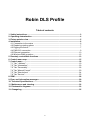
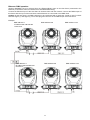
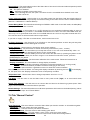
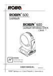
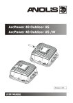
3. Fixture exterior view
1 - Front lens
2 - Tilt lock
3 - Pan lock
4 - Base
5 - Moving head
6 - Arm
The head should be locked for transportation- the tilt lock latch (2) and the pan lock latch (3) have to be in the
locked positions. To unlock the head, move these latches to unlock positions before operating the fixture.
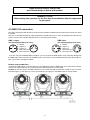
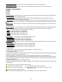
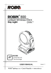
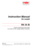
Rear panel of the base:
1 - 3-pin DMX output
2 - 5-pin DMX output
3 - Ethernet input-RJ45
4 - Fuse -live
5 - Power switch
6 - 3-pin DMX input
7 - 5-pin DMX input
8 - Fuse -neutral
9 - PowerCon
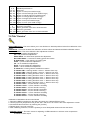
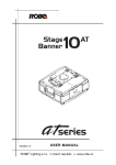
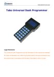
Front panel of the base:
1 - QVGA touch screen
2 - ESCAPE button
3 - NEXT button
4 - ENTER/DISPLAY ON button
5 - PREV button
The ENTER/DISPLAY ON button also serves for switching the display on when the fixture is disconnected
from the mains.
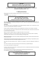
4. Installation
Fixtures must be installed by a Qualified electrician in accordance with all
national and local electrical and construction codes and regulation.
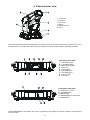
4.1 Connection to the mains
For protection
from electric shock, the fixture must be earthed!
The Robin DLS is equipped with auto-switching power supply that automatically adjusts to any 50-60Hz AC
power source from 100-240 Volts.
Install a suitable plug on the power cord if needed, note that the cores in the power cord are coloured according
to the following table. The earth has to be connected!
If you have any doubts about proper installation, consult a qualified electrician.
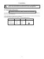
Core (EU)
Core (US)
Connection
Brown
Black
Live L
Light blue
White
Neutral
N
Yellow/Green
Green
Earth
Plug Terminal Marking
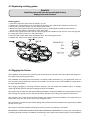
4.2 Replacing rotating gobos
DANGER!
Install the gobos with the device switched off only.
Unplug from mains before!
Rotating gobos
1. Disconnect the fixture from mains and allow it to cool.
2. Remove the bottom plastic cover of the head by loosening the 4 quarter-turn fasteners on the cover.
3. Gently pull up the gobo holder from the rotation gobo wheel.
4. Remove the spring gobo-lock with an appropriate tool (e.g. small-bladed screwdriver) and remove it.
Do not touch the surface of the pattern of the glass gobo.
5. Remove the original gobo and insert the new one (glazy side towards the light source). Insert the ring and
the spring-gobo lock to secure it in the gobo holder.
6. Insert the gobo holder back under the distance slots into rotating gobo wheel.
5. Replace the bottom cover before applying power.
4.3 Rigging the fixture
The installation of the fixture has to be built and constructed in a way that it can hold 10 times the weight for 1
hour without any harming deformation.
The installation must always be secured with a secondary safety attachment, e.g. an appropriate catch net.
This secondary safety attachment must be constructed in a way that no part of the installation can fall down if
the main attachment fails.
When rigging, derigging or servicing the fixture staying in the area below the installation place, on bridges,
under high working places and other endangered areas is forbidden.
The operator has to make sure that safety-relating and machine-technical installations are approved by an expert
before taking into operation for the first time and after changes before taking into operation another time.
The operator has to make sure that safety-relating and machine-technical installations are approved by an
expert after every four year in the course of an acceptance test.
The operator has to make sure that safety-relating and machine-technical installations are approved by a skilled
person once a year.
The projector should be installed outside areas where persons may walk by or be seated.
IMPORTANT! OVERHEAD RIGGING REQUIRES EXTENSIVE EXPERIENCE, including (but not limited to)
calculating working load limits, installation material being used, and periodic safety inspection of all installation
material and the fixture. If you lack these qualifications, do not attempt the installation yourself, but instead use
a professional structural rigger. Improper installation can result in bodily injury or damage to property.
The fixture has to be installed out of the reach of people.
If the fixture shall be lowered from the ceiling or high joists, professional trussing systems have to be used. The
fixture must never be fixed swinging freely in the room.
Caution: Fixtures may cause severe injuries when crashing down! If you have doubts concerning the safety of
a possible installation, do not install the moving head!
Before rigging make sure that the installation area can hold a minimum point load of 10 times the fixture’s
weight.
.
Danger of fire !
When installing the device, make sure there is no highly inflammable
material (decoration articles, etc.) in a distance of min. 0.5 m.
CAUTION!
Use 2 appropriate clamps to rig the fixture on the truss.
Follow the instructions mentioned at the bottom of the base.
Make sure that the device is fixed properly! Ensure that the
structure (truss) to which you are attaching the fixtures is secure.
The fixture can be placed directly on the stage floor or rigged in any orientation on a truss without altering its
operation characteristics .
For securing a fixture to the truss install a safety wire that can hold at least 10 times the weight of the fixture.
Use only safety wire with screw-on carabine. Pull the safety wire through the carrying handles and around the
truss as shown on the pictures below.
Note: If the safety wire is too long, whip it several times around the trusss in order to attach the fixture tight.
In case of an accident, the way of the falling fixture will be short.
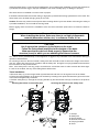
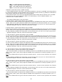
Truss installation
1.Bolt each clamp (1) to the omega holder (3) with M12 bolt and lock nut through the hole in the holder.
2.Fasten the omega holders on the bottom of the base by inserting both quick-lock fasteners (4) into the holes
of the base and tighten fully clockwise.
3. Pull the safety wire (2) through the carrying handles (5) and around the truss (6) as shown on the pictures
below.
Securing the fixture via one safety wire Securing the fixture via two safety wires
1-Clamps
2-Safety wire
3-Omega holder
4-Quick-lock fastener
5-Carrying handles
6-Truss
When installing fixtures side-by-side,
avoid illuminating one fixture with another!
DANGER TO LIFE!
Before taking into operation for the first time,the installation has to be approved
by an expert!
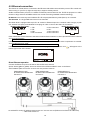
4.4 DMX-512 connection
The fixture is equipped with both 3-pin and 5-pin XLR sockets for DMX input and output.The sockets are wired
in parallel.
Only use a shielded twisted-pair cable designed for RS-485 and 3-pin or 5-pin XLR-plugs and connectors in
order to connect the controller with the fixture or one fixture with another.
DMX - output
XLR mounting-sockets (rear view):
DMX-input
XLR mounting-plugs (rear view):
1 - Shield
2 - Signal (-)
3 - Signal (+)
4 - Not connected
5 - Not connected
1 - Shield
2 - Signal (-)
3 - Signal (+)
4 - Not connected
5 - Not connected
If you are using the standard DMX controllers, you can connect the DMX output of the controller directly with
the DMX input of the first fixture in the DMX-chain. If you wish to connect DMX-controllers with other XLR-outputs, you need to use adapter-cables.
Building a serial DMX-chain:
Connect the DMX-output of the first fixture in the DMX-chain with the DMX-input of the next fixture. Always
connect one output with the input of the next fixture until all fixtures are connected.
Caution: At the last fixture, the DMX-cable has to be terminated with a terminator. Solder a 120 Ω resistor
between Signal (–) and Signal (+) into a 3-pin XLR-plug and plug it in the DMX-output of the last fixture.
4.5 Ethernet connection
The fixtures on a data link are connected to the Ethernet with ArtNet communication protocol.The control software running on your PC (or light console) has to support Art-Net protocol.
Art-Net communication protocol is a 10 Base T Ethernet protocol based on the TCP/IP.Its purpose is to allow
transfer of large amounts of DMX 512 data over a wide area using standard network technology.
IP address is the Internet protocol address.The IP uniquely identifies any node (fixture) on a network.
The Universe is a single DMX 512 frame of 512 channels.
The Robin DLS is equipped with 8-pin RJ- 45 socket for Ethernet input.Use a network cable category 5 (with
four “twisted” wire pairs) and standard RJ-45 plugs in order to connect the fixture to the network.
RJ-45 socket (front view):
RJ-45 plug (front view):
1- TD+ 5- Not connected
2- TD-
6- RX
3- RX+
7- Not connected
4- Not connected8- Not connected
Patch cables that connect fixtures to the hubs or LAN sockets are wired 1:1,that is,pins with the same numbers
are connected together:
1-12-2
3-3
4-4
5-5
6-6
7-78-8
If only the fixture and the computer are to be interconnected,no hubs or other active components are needed.
A cross-cable has to be used:
1-32-6
3-1
4-8
5-7
6-2
7-58-4
If the fixture is connected with active Ethernet socket (e.g. switch) the network icon
will appear at the
bottom right corner of the screen:
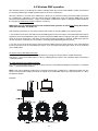
Direct Ethernet operation
Connect the Ethernet inputs of all fixtures with the Ethernet network.
Option “Artnet (gMaI or gMA2)" has to be selected from “Ethernet Mode” menu on the fixture.
Set IP address (002.xxx.xxx.xxx / 010.xxx.xxx.xxx) and the Universe.
(DMX address=144)
IP addres=002.168.002.004
Universe=1
(DMX address=48)
IP addres=002.168.002.003
Universe=1
(DMX address=1)
IP addres=002.168.002.002
Universe=1
An advised PC setting: IP address: 002.xxx.xxx.xxx / 010.xxx.xxx.xxx (Different from fixture IP addresses)
NET mask: 255.0.0.0
10
Ethernet / DMX operation
Options “Art2DMX” has to be selected from the “Ethernet Mode” menu on the first fixture (connected to the
Ethernet) in the fixture chain,next fixtures have standard DMX setting.
Connect the Ethernet-input of the first fixture in the data chain with the network. Connect the DMX output of
this fixture with the input of the next fixture until all fixtures are connected to the DMX chain.
Caution: At the last fixture, the DMX chain has to be terminated with a terminator. Solder a 120 Ω resistor
between Signal (–) and Signal (+) into a XLR-plug and connect it in the DMX-output of the last fixture.
Example:
DMX address=1
IP addres=002.168.002.002
Universe=0
DMX address=1
IP addres=002.168.002.003
Universe=1
DMX address=48
DMX address=48
11
DMX address=144
DMX address=144
4.6 Wireless DMX operation
The wireless version of the Robin DLS Spot is equipped with the Lumen Radio CRMX module and antenna
for receiving DMX signal. CRMX module operates on the 2.4 GHz band.
The item " Wireless " from the menu "DMX Input" allows you to activate receiving of wireless DMX (Personality--> DMX Input -->Wireless.). First two options from the "DMX Input" menu are stated in DMX chart as well
(channel Power/Special functions , range of 10-19 DMX). If DMX input option is changed by DMX command,
the change is permanently written into fixture´s memory.
DMX range of 10-19 switching fixture to the wired/wireless operation is active only during first 10 seconds after switching the fixture on.
After switching the fixture on, the fixture checks both modes of receiving DMX in the following order:
1. For the first five seconds, the fixture receives DMX signal from the wired input. If the Power/Special functions
channel is set at some DMX input option, the fixture will receive DMX value according to this option. If DMX input
option is set to the wired input , this option is saved and checking procedure is finished. If DMX input option is
not set, the fixture continues next 5 seconds in scanning wireless DMX signal-see point 2.
2. For the next 5 seconds the fixture receives wireless DMX signal and again detects if the Power/Special
functions channel is set at some DMX input option, if not, the fixture will take option which is set in the fixture
menu "DMX Input".
To link the fixture with DMX transmitter.
The fixture can be only linked with the transmitter by running the link procedure at DMX transmitter .
After linking , the level of DMX signal ( 0-100 %) is displayed in the menu item “Wireless State“ (Information
-->Wireless State).
To unlink the fixture from DMX transmitter.
The fixture can be unlinked from receiver via the menu item “ Unlink Wireless Adapter“ (Information--> Wireless
State --> Unlink Wireless Adapter.).
Note: If the option "Wireless In/XLR Out" is selected (Personality--> DMX Input -->Wireless In/XLR Out), the
fixture receives wireless DMX and sends the signal to its wired DMX output. The fixture behaves as " Wireless/Wired" adapter.
Example:
12
5. Remotely controllable functions
Virtual colour wheel
This wheel contains 236 colours including whites (2700K, 3200K, 4200K, 5600K and 8000K). Tungsten lamp
effect at whites 2700K and 3200K.
RGBW or CMY colour mixing system
The RGBW colour mixing system is based on red, green, blue and white high power LEDs. Option for switching
the fixture to the CMY colour mixing system is also available.
Effect wheel
The wheel rotates in both directions with variable speed which creates wide spectrum of graphic effects.
Rotating gobo wheel
The rotating gobo wheel includes 7 gobos rotating in both directions, indexable, replaceable "SLOT&LOCK”
metal gobos + open position. Gobo positioning and gobo selection speed is available as well as a gobo-shake
function.
Prism
The 3-facet prism rotates in both directions at different speeds, 16 prism/gobo macros are available.
Frost
Frost module provides variable frost for fine frosting.
Iris
Motorized adjustable iris, wide range of variable pulse effects.
Zoom
Motorized zoom unit enables zoom between 10 °- 45°.
Focus/Autofocus
Motorized focus allowes to focus beam from approx. 2 meters to infinity.
Special function autofocus allows to keep focused image during zooming . Select desired distance and effect
on which you need to focus at channel "Autofocus (priority & distance selection)" and use standard "Focus"
channel to focus the image.
Pan & Tilt
Pan/Tilt movement ranges 0-540°/0-280°.
Dimmer/Shutter unit
Smooth 0 - 100 % dimming is provided by the electronic control unit. This unit is also used for strobe effects
with variable speed.
Framing system
Framing system consists of four framing shutters . There is individual control of each shutter blade position
and angle, together with rotation of the complete framing module. As well as providing a sharp precise or soft
frame for the projected image, the system produces a new series of effects through pre-programmed shutter
blade shape and movement sequences.
13
Framing shutters identification
14
6. Control menu map
Default settings=Bold print
Tab
Level 1
Level 2
Level 3
Addressing
Settings
DMX Address
001-255
Ethernet Settings
Ethernet Mode
Level 4
Level 5
Disable
ArtNet
gMAI
gMA2
sACN
Ethernet To DMX
Off, On
IP Address/Net Mask
Default IP Address
Custom IP Address
Net Mask
ArtNet Universe
0-255
MANet settings
MANetI/II Universe
01-256
MANet Session ID
01-32
sACN Universe
00001-32000
sACN Priority
0-255
sACN Settings
Information
Fixture Times
Power On Time
Total Hours
Resetable Hours
LEDs On Time
Total Hours
Resetable Hours
Air Filters
Fixture Temperatures
LEDs Temperature
LEDs Board Temperature
Elapsed Time
Alert Period
10-300
Current
R, GW, B
Maximum NonRes.
R, GW, B
Maximum Res.
R, GW, B
Current
Maximum NonRes.
Maximum Res.
Ambient Temperature
Current
Maximum NonRes.
Maximum Res.
Base Temperature
Current
Maximum NonRes.
Maximum Res.
DMX Values
Pan
:
Dimmer Fine
Wireless State
Signal Quality
Unlink Wireless
Adapter
Power Channel state
RGB Colour Mixing
Mode
Pan/Tilt Speed Mode
Blackout if P/T Moves
Blackout if Gobo Moves
Software Versions
Display System
Module M
Module L-L
Module L-R
Module O
Module F-A
15
Level 6
Tab
Level 1
Level 2
Level 3
Level 4
Module F-B
Module G
Product IDs
Mac Address
RDM UID
RDM Label
View Logs
Fixture Errors
Pan Errors
:
Temp.Sensor Errors
Fixture States
Power On
Power Off
Fixture Position
Fixture Temperatures
LED Temperatures
Ambient Temperatures
Base Temperatures
Personality
User Mode
User A Settings
User B Settings
User C Settings
DMX Presets
Mode 1
Mode 2
Mode 3
View Selected Preset
DMX Input
Wired
Wireless
Wireless In/XLR Out
Pan/Tilt Settings
Pan Reverse
Off, On
Tilt Reverse
Off, On
Pan/Tilt Feedback
Off, On
Pan/Tilt mode
Time
Speed
Microphone Sensitivity
1-10-20
Blackout Settings
Blackout During M.C.
Off, On
Blackout while:
Pan/Tilt moving
Off, On
Gobo Wheels Moving
Off, On
Theatre Mode
Off
Auto
Silent
Colour Calibration
Mode
Off, On
Colour Mixing Mode
RGBW
0-100%
CMY
White 8000K point
On
Off
Init Effect Positions
Pan
0-255
:
Screen Settings
Dimmer Fine
0-255
Display Intensity
1-10
Screen Saver Delay
Off-10min.
Touchscreen Lock
Off-10min.
Recalibrate Touchscreen
Display Orientation
Normal
Inverted
Auto
16
Level 5
Level 6
Tab
Level 1
Level 2
Temperature Unit
°C,°F
Fan Mode
Auto
Level 3
Level 4
Level 5
Level 6
0-255
High
Date & Time Settings
Unlink Wireless
Adapter *
Default Settings
Manual Control
Reset Functions
Reset All Systems
Pan/Tilt reset
Gobo System Reset
Optics/Prism/Frost Res.
Iris Reset
Preset Effect Control
Pan
Position 1-Position 5
:
Manual Effect Control
Dimmer
Position 1- Position 5
Pan
0-255
:
Dimmer Fine
Stand -Alone
Test Sequences
0-255
Dynamic Mode
Static Mode
MusicTrigger
Off, On
Preset Playback
None
Pan
0-255
Tilt
0-255
Zoom
0-255
Focus
0-255
Start Step
1-100
End Step
1-100
Edit Program Steps
Step 1
Pan
:
:
:
Dimmer Fine
:
Step Time
0-25,5 sec.
Step 100
Pan
0-255
Test
Prg. 1
Prg. 2
Prg. 3
Play Program
Play Program 1
Play Program 2
Play Program 3
Edit Program
Edit Program 1
0-255
:
Service
Adjust DMX Values
Pan
0-255
:
Calibrations
Dimmer Fine
0-255
Calibrate Effects
Pan
0-255
:
Calibrate colours
Focus
0-255
Red
0-255
Green
0-255
Blue
0-255
White
0-255
Calibrate Driver
Load Default Calibrations
Update Software
17
Dimmer Fine
0-255
Step Time
0-25,5 sec.
7. Control menu
The Robin DLS Light is equipped with the QVGA Robe touch screen with battery backup which
allows to set the fixture´s behaviour according to your needs, obtain information on its operation, test its various parts and lastly program it, if it has to be used in a stand-alone mode.
The fixture´s menu can be controlled either by the control buttons or directly by touching the icon.
Control buttons on the front panel:
[ESCAPE] button used to leave the menu without saving changes.
[NEXT] , [PREV] buttons for moving between menu items and symbols, adjusting values.
[ENTER/Display On] button used to enter the selected menu (menu item) and to confirm adjusted value.
If the fixture is disconnected from mains, the button switches the touch screen on.
Icons used in the touch screen menu:
- [back arrow] used to move back to the previous screen (menu).
- [up arrow] used to move up on the previous page.
- [down arrow] used to move down on the next page.
- [confirm] used to save adjusted values, to leave menu or to perform desired action.
- [cancel] used to leave menu item without saving changes.
- [confirm+copy] used to save adjusted values and copy them to the next prog. step.
- [warning icon] used to indicate some error which has occurred in the fixture.
- [Ethernet] used to indicate Ethernet connected.
- [display turn] used to turn the display by 180°.
The menu page displays icons for each function that you can perform from the touch screen.
After switching the fixture on, the touch screen shows the screen with the ROBE logo:
Touch any part of the screen or press the [ENTER/Display On] button to display the initial screen with the current stored DMX address:
18
Note: The green icon at the top right corner of the screen indicates the level of the display battery charging. If
the whole icon is green, the battery is fully charged while the red icon indicates exhausted battery. The battery
charges during fixture operation, its charging lasts cca 6 hours.
We recommend that the fixture should be in operation at least 7 hours per week to keep the battery fully charged.
If you switch the fixture on and this screen will not appear till 1 minute, switch the fixture off and on again. If the
screen lights, the battery is exhausted. In case the screen still does not light, the battery is faulty.
This is also indicated by an error message "Faulty battery" and if such an error message appears the battery
should be replaced immediately. The lifetime of the battery is highly dependent on ambient temperature (and
consequently on base temperature). If the maximum ambient temperatures (as recorded and displayed in menu:
Information -> Fixture Temperatures -> Ambient Temperature -> Maximum NonRes.) are kept within the specified limits, the battery should last for at least two years. Shell the ambient temperatures exceed the specified
maximum temperature, the lifetime of the batteries could be considerably shortened even up to just one year
or less and also result in physical damage (battery leakage) or unreliable fixture functions.
Damage caused by batteries failed due to exceeded maximum ambient temperature cannot be claimed under
warranty terms.
Touch the green arrow at the bottom right corner of the screen or press the [ENTER/Display On] button to enter
the " Address" menu.
Each item (such as a Tab, menu item, text box, icon) may be selected from a screen by simply touching the
item in the list or by pressing the [NEXT] or [PREV] buttons to scroll through list items. With each press, the
next item is highlighted. Press [ENTER/Display On] to select the highlighted item.
Before first fixture operation, set current date and time in the menu "Date &Time
Setings" (menu path: Personality--> Date &Time Setings).
7.1 Tab " Address"
Settings - Select the menu to set desired fixture address setting.
DMX Address - Select the menu to set the DMX start address.
Ethernet Settings - The menu allows all needed settings for the Ethernet operation
Ethernet Mode
Disable - The option disables Ethernet operation.
Artnet - Fixture receives Artnet protocol
gMAI - Fixture receives MANet I protocol
gMA2 - Fixture receives MANet 2 protocol
sACN - Fixture receives sACN protocol
Ethernet To DMX - Fixture receives protocol from the Ethernet input and sends DMX
data to its DMX output (fixture works as an "Ethernet/DMX converter", next fixture can be connected to its DMX output and you can build a standard DMX chain by connecting another fixtures.
Only one fixture has to be connected to the Ethernet.
IP Address/Net Mask - Select this menu to set IP address. IP address is the Internet protocol
address.The IP uniquely identifies any node (fixture) on a network.
There cannot be 2 fixtures with the same IP address on the network!
19
Default IP Address -Preset IP address, you can set up only first byte of IP address
(2 or 10) e.g. 002.019.052.086.
Custom IP Address - The option enables to set up all bytes of IP address.
Net Mask - The option enables to set up all bytes of Net Mask.
ArtNet Universe - Use this item to set a Universe (0-255). The Universe is a single DMX
512 frame of 512 channels.
MANet Settings - Use this menu to set parameters for MANet operation.
MANet Universe I/II - The value of this item can be set in range 1-256.
MANet Session ID - The value of this item can be set in range 1-32.
sACN Settings - Use this menu to set parameters for sACN operation.
sACN Universe - The value of this item can be set in range 1-32000.
sACN Priority - The value of this item can be set in range 0-255.
7.2 Tab "Information"
Fixture Times - The menu provides readouts of fixture and LED module operation hours.
Power On Time Hours - Select this menu to read the number of fixture operation hours.
Total Hours - The item shows the total number of the operation hours since the Robin DLS has been fabricated.
Resetable Hours - The item shows the number of the operation hours that the Robin DLS has been powered on since the counter was last reset.
In order to reset this counter to 0, touch the text box next to the item "Resetable Hours:"
LEDs On Time - Select this menu to read the number of LEDs operation hours for each colour (R,G,B,W).
In order to reset some counter to 0, touch the yellow text box next to desired colour.
Air Filters - Regular cleaning of the air filters is very important for the fixture´s life and performance.
Bild-up of dust, dirt and fog fluid residues reduces the fixture´s light output and cooling ability.
The two items of this menu help you to keep cleaning period of the air filters.
Alert period - Cleaning schedule for the fixture depends on the operating environment.
It is therefore impossible to specify accurate cleaning interval. This item allows
you to change the cleaning interval of the air filters. This "alert" value is 300 hours and it
is set as default. Inspect the fixture within its 300 hours of operation to see whether cleaning
is necessary. If cleaning is required, clean all air filters and change the value in this menu
on acceptable level. Min. level of alert period is 10 hours, max. is 300 hours.
Elapsed Time - The item allows you to read the time which remains to cleaning air filters.
The time period is set in the menu mentioned above.
Expired time period is signalled by a negative mark (-) at the time value and a warning icon
on the display.
Clean the filters and reset this menu item (by touching the text box next to the item
"Elapsed Time").
Fixture Temperatures - The menu is used to view temperatures of the fixture´s inside.
LEDs temperatures - The menu shows temperature on the LED PCBs (R-red LEDs, GW-green + white
LEDs, B-blue LEDs).
Cur. - A current temperature of the LED PCB.
Max. - A maximum temperature of the LED PCB since the fixture has
been fabricated.
Max. Res. - A maximum temperature of the LED PCB since the counter
was last reset.
In order to reset some counter to 0, touch desired text box under item "Max.Res."
LEDs Board Temperature - The menu shows temperature in the fixture head on the LEDs control PCB.
Current - A current temperature on the LEDs control PCB.
Maximum NonRes. - A maximum temperature on the LEDs control PCB since
the fixture has been fabricated.
20
Maximum Res. - A maximum temperature on the LEDs control PCB since the counter
was last reset.
In order to reset this counter to 0, touch the text box next to the item "Maximum Res."
Ambient Temperature - The menu shows temperature of the induced air on the fan in the fixture base .
Current - A current temperature of the induced air in the fixture base.
Maximum NonRes. - A maximum temperature of the induced air in the fixture base since
the fixture has been fabricated.
Maximum Res. - A maximum temperature of the induced air in the fixture base since
since the counter was last reset.
In order to reset this counter to 0, touch the text box next to the item "Maximum Res."
Base Temperature - The menu shows temperature in the fixture base (on the display PCB).
Current - A current temperature in the fixture base.
Maximum NonRes. - A maximum temperature in the fixture base since the fixture has
been fabricated.
Maximum Res. - A maximum temperature in the fixture base since the counter
was last reset.
In order to reset this counter to 0, touch the text box next to the item "Maximum Res."
DMX Values - The menu is used to read DMX values of each channel received by the fixture.
Wireless State - The menu serves for reading of the wireless operation status.
Unlink Wireless Adapter - The item serves for unlinking the fixture from the transmitter.
Power Channel State - Select this item to see current setting of the functions, which can be set by menu items
in "Personality" as well as by DMX command at channel "Power/Special functions".
Software Version - Select this item to read the software version of the fixture modules:
Display System - A display processor on the display board in the fixture base
Module M - Pan/Tilt processor
Module L-L - LEDs control processor
Module L-R - LEDs control processor
Module O - Focus/zoom/prism/frost/ processor
Module F-A -Framming shutters processor
Module F-B - Framming shutters + Iris processor
Module G - Rot. gobo/Effect wheel processor
Product IDs - The menu is used to read the MAC Address ,RDM UID and RDM Label.
View Logs - Use this menu to read fixture´s data which have been recorded during fixture operation. This
colected data allows easier troubleshooting.
Fixture Errors - Use this menu to read fixture errors which have occured during fixture operation.
There is a list of error folders:
Pan Errors
Prism Errors
Tilt Errors
Prism Rotation Errors
Dimmer 1 Errors
Frost Errors
Dimmer 2 Errors
Clean Air Filters
Colour Errors
Overheated
Zoom Errors
Gobo Errors
Temp. Sensor Errors
Gobo Carousel Errors
Clean Air Filters
Effect Wheel Errors
Iris Errors
Focus Errors
Fixture States - Recorded following actions: Fixture On, Fixture Off.
Fixture Position - Recorded installation positions of the fixture:
21
Fixture Temperatures - Recorded temperatures which have exceeded defined levels.
Note: The log buffer can contain 8000 records max. If the buffer is full, old data will be overwritten.
7.3 Tab "Personality"
User mode - The Robin DLS allows you to recall up to 3 user settings. After switching the fixture on for the
first time, the User A settings is active. Now all changes made in the “Personality” menu , ”Addressing” menu
and the “Music Trigger“ and “ Preset Playback“ items from the “Stand-alone” menu are saved to the User A
settings. If you now select the User B settings, from this moment the changes made in these menus will be
saved to the User B settings. After switching the fixture off and on, the User B setting is active. In this way you
may use the 3 fixture operating behaviours.
User A Settings - the function recalls the user A settings.
User B Settings - the function recalls the user B settings.
User C Settings - the function recalls the user C settings.
DMX Preset - Use the menu to select desired channel mode.
Mode 1 - 47 control channels
Mode 2 - 38 control channels
Mode 3 - 36 control channels
View Selected Preset - Use the menu to display channels included in the selected mode.
DMX Input- Use the menu to select mode of receiving DMX signal.
Wired - DMX signal is received by means of the standard DMX cable.
Wireless - DMX signal is received by means of the inbuilt wireless module.
Wireless In/XLR Out- the fixture receives wireless DMX and sends the signal to its wired DMX output.
The fixture behaves as " Wireless/Wired" adapter.
The options "Wired" and "Wireless" are also stated in DMX chart (channel Power/Special functions).
Pan/Tilt Settings - Use the menu set behaviour of both pan and tilt movements.
Pan Reverse - The item allows to invert pan movement.
Tilt Reverse - The item allows to invert tilt movement.
Pan/Tilt Feedback - The item allows to return the mowing head to the required pan/tilt position after
changing the position by an external force if this option is set on.
Note. Be careful, the Pan/Tilt Feedback should be permanent On, the option Off is not suitable for standard
operation and the head of the fixture can be damaged!
Pan/Tilt mode - Use this menu to set the mode of the pan/tilt movement
Time mode – The pan and tilt will move with different speeds and they will come at
the same time to the end point of their tracks (pan and tilt use their optimal speeds).
Time of the pan/tilt movement (25.5 sec. max.) is set by the channel "Pan/Tilt speed, Pan/Tilt
time".
Speed Mode - Both Pan and tilt will move with the same speed as adjusted at the channel
"Pan/Tilt speed, Pan/Tilt time".
Microphone Sensitivity - Enter the menu if you want to adjust the microphone sensitivity from 1 (max.) to 20
(min.).
Blackout Settings - Use the menu if you need to close the light output under certain conditions which are
described below
Blackout DMC - Blackout during movement correction. Set this option On if you wish to close light
output during the time when the head goes to its correct position, which has been changed by an
external force.
Active Blackouts - Use this menu if you wish to close the light output during effect changes.
Pan/Tilt Moving - The menu item enables to close light output while the pan/tilt coordinates
are changing.
Gobo Wheel Moving - The menu item enables to close light output while the rot. gobo wheel or the static gobo wheel is moving.
22
Theatre Mode - The mode reduces noise of the fixture due to fine control of fans and reduced speed of pan/tilt
movement and gobo/prism rotation.
Off - The option is disabled
Auto - Automatic regulation of fans noise level.
Silent - After selecting this item, the option "Fan Noise Level" is accessible where desired level of the fans noise can be set.
Colour Calibration Mode - If the function is on, the white output from the fixture (and also mixed colours) is
more uniform. Each colour is dynamically corrected according to the value set in the menu "Calibrate Effects"
(Service-> Calibrations-> Calibrate Effects).
Colour Mixing Mode - This item allows switching into RGBW or CMY mode. In the CMY mode, the white(8bit)/
white (16) bit channels are not active.
White Point 8000K - If the function is on, at CTO channel you can set desired calibrated white in range of
8000K-2700K. Necessary condition is , that RGBW channels has to be full or set at the same DMX value. Another way, how to get desired white colour is to set RGB channels to 0 and use only white channel and CTO.
CTO function does not effects mixed colours except whites.
If you wish to "apply" CTO filter on mixed colours, set this menu item to Off.
Init Effect Positions - Use the menu to set all effects to the desired positions at which they will stay after
switching the fixture on without DMX signal connected.
Screen Settings - Use this menu to change the touch screen settings.
Display Intensity - The item allows to control the intensity of the screen (1-min., 10-max.).
Screen saver Delay - The item allows you to keep the screen on or to turn it off automatically after 1-10
minutes after last touch (or pressing any button on the control panel).
Touchscreen Lock - The item allows you to lock the screen after last touch (or pressing any button on the
control panel). The time delay can be set in range of 1-10 minutes.To unlock the screen, press the
[ENTER/Display On] button.
Recalibrate Touchscreen - The item starts calibration of the touchscreen. Follow the instructions on
the screen.
Display Orientation - The menu allows to change display orientation.
Normal - Standard display orientation if the fixture is placed horizontally (e.g. on the ground).
Inverted - Inverted orientation (needed if the fixture is hanging on the truss).
Auto - The option activates a gravitation sensor for automatic screen orientation.
Note: Auto option is set as default. You change the display orientation by touching the icon
on the display,
an the option set in the "Display Orientation" menu is temporarily overriden.
Temperature unit - Use the menu item to change temperature unit from °C to °F.
Fan Mode - Use the menu to set the fixture fans to max. power mode ("High") or to auto-control mode
("Auto").
Date & Time Settings - Use this menu to set current date and time for the fixture log system (menu "View
Logs"). Set this menu item before first fixture operation.
Default Settings - The menu item allows to set all fixture parameters in this menu to the default (factory) values
except items "DMX Input" and "Theatre Mode ".
7.4 Tab "Manual Control"
Reset Functions - The menu allows to reset the fixture either per function modules or all modules together.
Total Reset - The item resets all function modules.
Pan/Tilt Reset - The item resets a pan and tilt movement.
Gobo System Reset - The item resets a static/rotating gobo wheel.
Optics/Prism/Frost Res. - The item resets a zoom, focus, prism and a frost module.
Iris/Fr. Shutters Effect Wheel Reset - The item resets an iris module and framing shutters.
23
Preset Effect Control - Use the menu to show preset positions of each channel effect.
Manual Effect control - Use the menu to control all fixture channels by means of the control panel.
7.5 Tab "Stand-alone"
Test Sequences -Use the menu to run a test/demo sequences without an external controller, which will show
you some possibilities of using Robin DLS.
Dynamic Mode - This mode uses all Robin DLS functions including pan/tilt movement and therefore
is good for a complete introduction of the fixture.
Static Mode - This mode is suitable for projections on the wall, ceiling or ground without any pan/tilt movement. Adjust the pan, tilt, zoom and focus to desired positions an start test sequences by touching the green
icon.
Music Trigger - Use the item to activate the sound control of the running program via the built-in microphone.
Preset Playback - This menu allows you to select the program which will be played in a loop after switching
the fixture on (the option is commonly used in a stand-alone operation without an external controller).
None - The option disables “Presetting playback” function.
Test - The option starts the test sequences.
Prog. 1 - The option starts user program No. 1.
Prog. 2 - The option starts user program No. 2.
Prog. 3 - The option starts user program No. 3.
Play program - Use the menu to run desired program in a loop.
Play Program 1 - The option starts user program No.1.
Play Program 2 - The option starts user program No. 2.
Play Program 3 - The option starts user program No. 3.
Edit Program - Use the menu to create or to edit desired program. The Robin DLS offers 3 free programs,
each up to 100 steps.
Edit Program 1 - The option allows to edit user program No.1.
Edit Program 2 - The option allows to edit user program No.2.
Edit Program 3 - The option allows to edit user program No.3
To edit program:
1. Touch the item which you want to edit (“Edit Program 1” - “Edit Program 3”).
2. Touch the item "Edit Program Steps".
3. Touch the item "Step 1".
4 From the list of effects touch desired effect and set its value. Browse throw the list by touching the [up arrow]
and [down arrow] and set all desired effects.
An item "Step Time" (value of 0-25.5 sec.) is the time during which effects last in the current step
5. Save adjusted effects to the current step by touching the [confirm] or save and copy them to the following
step by touching the [confirm+copy]. By touching the text box "Preview" next to the current program step you
can view created scene.
6. Repeat the steps 4 and 5 for next program steps.
7. After editing desired program steps, adjust the length of the program by touching the text boxes "Start Step"
and "End Step".
Meaning of the icons used in the "Edit Program" menu:
- moves down on the next page
- saves adjusted values and leaves menu
- moves up on the previous page
- saves values to the current step and copy them to the
following prog. step
- leaves menu without saving values
There is a chart describing behaviour of items "Pan/Tilt Macro" and "P./T. Macro Speed".
24
DMX
0-9
10 - 31
32 - 63
64 - 95
96 - 127
128 - 159
160 - 191
192 - 223
224 - 255
Pan/Tilt Macro
Disabled pan/tilt macro
Reserved
Figure of circle (from small to large)
Figure of horizontal eight (from small to large)
Figure of vertical eight (from small to large)
Figure of rectangle (from small to large)
Figure of triangle (from small to large)
Figure of star (from small to large)
Figure of cross (from small to large)
0
1 - 127
128 - 129
130 - 255
Pan/Tilt Macro Speed
No macro generation
Macro generation from fast to slow-forwards
No macro generation
Macro generation from slow to fast-backwards
7.6 Tab "Service"
Adjust DMX Values - The menu allows you to set all effects to desired positions before fine calibration of the
effects .
Calibrations - This menu enables fine calibration of fixture effects and download default calibration values.
Calibrate Effects - The menu allows the fine adjustment of effects.
Pan- a pan position fine adjustment
Tilt - a tilt position fine adjustment
Effect Wheel - an effect wheel position fine adjustment
Rot. Gobo Wheel - a carousel of rotating gobos fine rotation
R. Gobo Index - a fine indexing of rotating gobo
Prism - a prism module fine adjustment
Iris - an iris module fine adjustment
Zoom - a zoom module fine adjustment
Focus - a focus module fine adjustment
Fr. Shutt.rot- a framing shutters modele fine rotation
Fr. Shutter I M1- a framing lamella 1 motor 1 -distance from stop
Fr. Shutter I M2- a framing lamella 1 motor 2 - distance from stop
Fr. Shutter 2 M1- a framing lamella 2 motor 1 - distance from stop
Fr. Shutter 2 M2- a framing lamella 2 motor 2 - distance from stop
Fr. Shutter 3 M1- a framing lamella 3 motor 1 - distance from stop
Fr. Shutter 3 M2- a framing lamella 3 motor 2 - distance from stop
Fr. Shutter 4 M1- a framing lamella 4 motor 1 - distance from stop
Fr. Shutter 4 M2- a framing lamella 4 motor 2 - distance from stop
Fr. Shutter 1 Mov. - a Fram. lamella 1 mowing
Fr. Shutter 1 Swiv. - a Fram. lamella 1 swivelling
Fr. Shutter 2 Mov. - a Fram. lamella 2 mowing
Fr. Shutter 2 Swiv.- a Fram. lamella 2 swivelling
Fr. Shutter 3 Mov. - a Fram. lamella 3 mowing
Fr. Shutter 3 Swiv. - a Fram. lamella 3 swivelling
Fr. Shutter 4 Mov. - a Fram. lamella 4 mowing
Fr. Shutter 4 Swiv. - a Fram. lamella 4 swivelling
Calibration of the effects via the control board
1. Disconnect DMX controller from the fixture and enter the "Calibrate Effects" menu.
2. Use the [up arrow] and [down arrow] to find "Pan" and touch it to enter the fine effect adjustment screen.
3. Set desired value and save it by touching the [confirm].
4. Repeat steps 2 and 3 for next item
5. After calibrating all effects, touch the [confirm] to save all adjusted values and reset the fixture.
Calibrate Colours - The menu serves for adjusting of LEDs saturation to achieve colour temperature
of 5600K for white output.
25
Red - a red LEDs saturation fine adjustment
Green - a green LEDs saturation fine adjusment
Blue - a blue LEDs saturation fine adjustment
White - a white LEDs saturation fine adjustment
Calibration of the white colours via DMX controller
1. Connect DMX controller to the fixture , open shutter and dimmer, set zoom at 128 DMX ,focus image and set
the "Virtual Colour Wheel" channel at 8000K. Aim the light beam on the lux meter (e.g. Minolta CL-200 Chroma
meter) which is placed at min distance of 2.5 from the fixture.
2. The channel "Power" has to be set at 240 DMX (disable theatre mode) and the channel "CTC" at 0 DMX.
3. Set the menu item "Colour Calibration Mode" to On (Personality-> Colour Calibration Mode-> On).
4. Enter the menu "Calibrate Effects".
For example, DMX mode 3 is set in the fixture.
5. Set the channel " Virtual Colour Wheel" (ch.5) at 8000K
6. Set the channel "White" (ch.58) from the calibration protocol at 255DMX and by means of the channels "Red",
"Green", "Blue" (ch.55, 56,57) adjust the 8000K colour temperature as exactly as possible (∆u´v´=+/-0.0005)
7. After adjusting of 8000K colour temperature, set the channel "CTC" (ch.10) at 1 for a few seconds until a
light blink will appear. After that, set this channel back to 0 DMX.
8. Set the channel " Virtual Colour Wheel" (ch.5) at 4200K.
9. Set the channel "White" (ch.58) from the calibration protocol at 200 DMX and by means of the channels "Red",
"Green", "Blue" (ch.55, 56,57) adjust the 4200K colour temperature as exactly as possible (∆u´v´=+/-0.0005)
10 After adjusting of 4200K colour temperature, set the channel "CTC" (ch.10) at 1 for a few seconds until a
light blink will appear. After that, set this channel back to 0 DMX.
11. Set the channel " Virtual Colour Wheel" (ch.5) at 3200K.
12. Set the channel "White" (ch.58) from the calibration protocol at 60 DMX and by means of the channels "Red",
"Green", "Blue" (ch.55, 56,57) adjust the 3200K colour temperature as exactly as possible (∆u´v´=+/-0.0005)
13 After adjusting of 3200K colour temperature, set the channel "CTC" (ch.10) at 1 for a few seconds until a
light blink will appear. After that, set this channel back to 0 DMX.
14. Set the channel " Virtual Colour Wheel" (ch.5) at 2700K.
15. Set the channel "White" (ch.58) from the calibration protocol at 50 DMX and by means of the channels "Red",
"Green", "Blue" (ch.55, 56,57) adjust the 2700K colour temperature as exactly as possible (∆u´v´=+/-0.0005)
16 After adjusting of 2700K colour temperature, set the channel "CTC" (ch.10) at 1 for a few seconds until a
light blink will appear. After that, set this channel back to 0 DMX.
17. Set the channel "Power" at 241 DMX (enable theatre mode).
18. Set the channel " Virtual Colour Wheel" (ch.5) at 8000K.
Set the channel "White" (ch.58) from the calibration protocol at cca 60 DMX and by means of the channels
"Red", "Green", "Blue" (ch.55, 56,57) adjust the 8000K colour temperature as exactly as possible (∆u´v´=+/0.0005).
Note: Sum of DMX values for green and white channel must be < 319 for correct operation of the Theatre
Mode.
19. After adjusting of 8000K colour temperature, set the channel "CTC" (ch.5) at 1 for a few seconds until a
light blink will appear. After that, set this channel back to 0 DMX.
20. Set the channel " Virtual Colour Wheel" (ch.5) at 5600K.
Set the channel "White" (ch.58) from the calibration protocol at cca 50 DMX and by means of the channels
"Red", "Green", "Blue" (ch.55, 56,57) adjust the 5600K colour temperature as exactly as possible (∆u´v´=+/0.0005).
Note: Sum of DMX values for green and white channel must be < 319 for correct operation of the Theatre
Mode.
21. After adjusting of 5600K colour temperature, set the channel "CTC" (ch.10) at 1 for a few seconds until a
light blink will appear. After that, set this channel back to 0 DMX.
22. Set the channel " Virtual Colour Wheel" (ch.5) at 4200K.
Set the channel "White" (ch.58) from the calibration protocol at cca 60 DMX and by means of the channels
"Red", "Green", "Blue" (ch.55, 56,57) adjust the 5600K colour temperature as exactly as possible (∆u´v´=+/0.0005).
Note: Sum of DMX values for green and white channel must be < 319 for correct operation of the Theatre
Mode.
26
23. After adjusting of 5600K colour temperature, set the channel "CTC" (ch.10) at 1 for a few seconds until a
light blink will appear. After that, set this channel back to 0 DMX.
24. Set the channel "Power" at 240 DMX (disable theatre mode).
25. Set the channel " Virtual Colour Wheel" (ch.5) at 5600K.
Set the channel "White" (ch.58) from the calibration protocol at 255 DMX and by means of the channels
"Red", "Green", "Blue" (ch.55, 56,57) adjust the 5600K colour temperature as exactly as possible (∆u´v´=+/0.0005).
26. After adjusting of 5600K colour temperature, touch
on fixture display to save adjusted values and
reset the fixture.
Calibration protocol:
Effect
Mode 1
Mode 2
Mode 3
Pan
channel 48
channel 39
channel 37
Tilt channel 49
channel 40
channel 38
Ef. wheel
channel 50
channel 41
channel 39
Rot. Gobo Wheel
channel 51
channel 42
channel 40
Rot. Gobo Index.
channel 52
channel 43
channel 41
Prism
channel 53
channel 44
channel 42
Iris
channel 54
channel 45
channel 43
Zoom
channel 55
channel 46
channel 44
Focus
channel 56
channel 47
channel 45
Fr. Shutters rot.
channel 57
channel 48
channel 46
Fr. Shutter I M1
channel 58
channel 49
channel 47
Fr. Shutter I M2
channel 59
channel 50
channel 48
Fr. Shutter 2 M1
channel 60
channel 51
channel 49
Fr. Shutter 2 M2
channel 61
channel 52
channel 50
Fr. Shutter 3 M1
channel 62
channel 53
channel 51
Fr. Shutter 3 M2
channel 63
channel 54
channel 52
Fr. Shutter 4 M1
channel 64
channel 55
channel 53
Fr. Shutter 4 M2
channel 65
channel 56
channel 54
Fr. Shutter 1 mov.
channel 66
channel 57
channel 55
Fr. Shutter 1 swiv.
channel 67
channel 58
channel 56
Fr. Shutter 2 mov.
channel 68
channel 59
channel 57
Fr. Shutter 2 swiv.
channel 69
channel 60
channel 58
Fr. Shutter 3 mov.
channel 70
channel 61
channel 59
Fr. Shutter 3 swiv.
channel 71
channel 62
channel 60
Fr. Shutter 4 mov.
channel 72
channel 63
channel 61
Fr. Shutter 4 swiv.
channel 73
channel 64
channel 62
Red
channel 74
channel 65
channel 63
Green
channel 75
channel 66
channel 64
Blue
channel 76
channel 67
channel 65
Calibrate Driver - The function runs recalibration of the LED driver. It is suitable use this function when some
non-uniform colour changes appear during colour saturation or if software upgrade is executed.
Load Default Calibrations - The item loads default (factory) calibration values.
Updating software - The menu item allows you to update software in the fixture via either serial or USB port
of PC.
The following are required in order to update software:
- PC running Windows 95/98/2000/XP or Linux
- DMX Software Uploader
- Flash cable RS232/DMX No.13050624 (if you want to use a serial port of PC)
- Robe Universal Interface (if you want to use an USB port of PC)
Note 1: Software update should execute a qualified person. If you lack qualification, do not attempt the updateyourself and ask for help your ROBE distributor.
Note 2: DMX address, IP address, programs 1-3 and all items in the menu "Personality" will be set to their
default (factory) values.
27
To update software in the fixture:
I. Installation of the DMX Software Uploader.
1. DMX Software Uploader program is available from the ROBE web site at WWW.robe.cz.
2. Make a new directory ( e.g. Robe_Uploader) on your hard disk and download the software to it.
3. Unpack the program from the archive. If the Robe fixture is produced in both magnetic
and electronic ballast version, name of DMX Software Uploader is the same for both versions.
II.Fixture software updating.
1.Determine which of your ports is available on your PC and connect it:
- with the DMX input of the fixture if you using the flash cable RS232/DMX
- with the DMX output of the Robe Universal Interface if you using the USB cable.
Disconnect the fixture from the other fixtures in a DMX chain. Turn both the computer and
the fixture on. Make sure the lamp is switched off (only if the fixture involves a lamp).
2. Switch the fixture to the updating mode by touching the "Updating Software " item
Note: If you do not want to continue in software update, you have to switch off and on the fixture
to escape from this menu.
We recommend to cancel all running programs before starting the Software Uploader.
3. Run the Software Uploader program. Select desired COM and then click on the Connect button.
(Select COM if the serial port is used or DreamBox1 if the USB port is used).
If the connection is OK, click on the “Start Uploading button“ to start uploading. It will take several
minutes to perform software update.
If the option "Incremental Update" is not checked, all processors will be updated (including
processors with the same software version).
If you wish to update only later versions of processors, check the “Incremental Update box“.
Avoid interrupting the process. Update status is being displayed in the Info Box window.
When the update is finished, the line with the text “The fixture is successfully updated“ will appear in
this window and the fixture will reset with the new software.
After updating, the fixture, calibration of the LED driver may start (it depends on software version
before calibration). The calibration will last cca 5 minutes (time depends on LED module temperature),
do not interupt this process.
8. RDM
This fixture supports RDM operation. RDM (Remote Device Management) is a bi-directional communications
protocol for use in DMX512 control systems, it is the new open standard for DMX512 device configuration and
status monitoring.
The RDM protocol allows data packets to be inserted into a DMX512 data stream without adversely affecting
existing non-RDM equipment. By using a special „Start Code,“ and by complying with the timing specifications
for DMX512, the RDM protocol allows a console or dedicated RDM controller to send commands to and receive
messages from specific moving lights.
RDM allows explicit commands to be sent to a device and responses to be received from it.
The list of commands for Robin DLS is the following.
Parameter ID
Discovery command SET command
DISC_UNIQUE_BRANCH
*
DISC_MUTE
*
DISC_UN_MUTE
*
GET command
DEVICE_INFO
*
SUPPORTED_PARAMETERS
*
SOFTWARE_VERSION_LABEL
*
DMX_START_ADDRESS
*
*
IDENTIFY_DEVICE
*
*
DEVICE_MODEL_DESCRIPTION
*
MANUFACTURER_LABEL
*
*
DEVICE_LABEL
*
SENSOR_DEFINITION
*
SENSOR_VALUE
*
*
DISPLAY_INVERT
28
*
DISPLAY_LEVEL
*
*
PAN_INVERT
*
*
TILT_INVERT
*
*
DEVICE_RESET
*
DMX_PERSONALITY
*
*
DMX_PERSONALITY_DESCRIPTION
*
STATUS_MESSAGES
*
STATUS_ID_DESCRIPTION
*
...Another options for this command (only for Robe´s fixtures):
value PARAMETER_DATA=0x84 - lamp OFF by DMX value on DMX channel
value PARAMETER_DATA=0x88 - lamp OFF if DMX is not present
2
...Commands relative resetable values
1
9. Error and information messages
Occurred errors during fixture operation are signalled by the yellow warning icon at the bottom line of the
screen:
Touch the warning icon or press the [ESCAPE] button to display error messages.
List of error and information messages:
Temper.Sensor Error
The message informs you that the communication betwen the head temperature sensor and the main processor failed..
Tilt Error 1 (Tilt Error 2)
This message will appear after the reset of the fixture if the head´s magnetic-indexing circuit malfunctions (sensor failed or magnet is missing) or the stepping motor is defective or its driving IC on the PCB. The head is not
located in the default position after the reset.
Pan Error 1 (Pan Error 2)
This message will appear after the reset of the fixture if the yoke´s magnetic-indexing circuit malfunctions (sensor failed or magnet is missing) or the stepping motor is defective or its driving IC on the PCB. The yoke is not
located in the default position after the reset of the fixture.
Prism Error 1 (Prism Error 2 )
The messages will appear after the reset of the prism wheel if this wheel is not located in the default position.
Zoom Error 1 (Zoom Error 2 )
The messages will appear after the reset of the zoom module if the zoom lens is not located in the default
position.
Focus Error 1 (Focus Error 2 )
The messages will appear after the reset of the focus module if the focus lens is not located in the default.
Gobo Carousel Error 1 (Gobo Carousel Error 2 )
The messages will appear after the reset of the rotating gobo wheel if this wheel is not located in the default
position.
Gobo rotation Error 1 (Gobo Rotation Error 2 )
The messages will appear after the reset of the rotating gobo wheel if the rotating gobos are not located in the
default positions.
Effect wheel Error 1 (Animation wheel Error 2 )
The messages will appear after the reset of the static gobo wheel if this wheel is not located in the default
position.
Clean Air Filters
The message informs that the item "Elapsed Time" in the "Fixture Information" menu is at 0 value. Clean air
filters and reset this counter.
29
10. Technical Specifications
Electrical
Power supply:.........................electronic auto-ranging
Input voltage range:............... supply 100-240V, 50-60Hz
Live Fuse:...............................T 8 A
Neutral Fuse:..........................T 8 A
Max. power consumption* (RGBW=full):...............550W at 230V ; power factor= 0.97; I=2.4A
Typical power consumption* if only one colour is on:
Red=full:...............160W at 230V ; power factor= 0.85; I=0.8A
Green=full:..............210W at 230V ; power factor= 0.9; I=0.98A
Blue=full:..............185W at 230V ; power factor= 0.88 I=0.88A
White=full:..............215W at 230V ; power factor= 0.9; I=1 A
*Allow for a deviation of +/-10%
Optic
Light source: RGBW LED module
RGBW or CMY colour mixing +CTC
Min. LED life expectancy: 20.000 hours
Virtual colour wheel
237 colours including whites (2700K, 3200K, 4200K, 5600K and 8000K)
Halogen lamp effect at whites 2700K and 3200K
Rainbow effect with in both directions with variable speed
Effect wheel
Rotation in both directions with variable speed
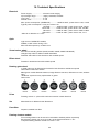
Rotating gobo wheel
7 metal gobos can be indexed and rotated in both directions at different speeds
Gobo wheel continuous rotation
Metal gobos: outside diameter=26.9 mm, image diameter =22.5mm, thickness=0.15 mm, steinless
steel
"Slot&lock" system for easy replacement of gobos
Gobo order:
Prism
Rotating 3-facet 11° prism with continuous rotation in both directions
Iris
Motorized iris for different beam diameters
Frost filter
Separate,variable frost filter
Framing shutters module
Four framing shutters can be moved or swivelled to desired position separately
Each framing shutter can move up to 80% of the beam and swivel +/- 25°
Complete framing shutters module can rotate +/- 45°
30
Zoom
Strobe
Smooth & Fast blade movements for creating mid-air effects, variable speed
Pre-programmed shape and blade sequence
Linear motorized zoom
Min. beam angle :10° (gobo position)
Max. beam angle: 45°(free hole)
Strobe effect with variable speed (0.3 - 20Hz)
Dimmer
Smooth dimmer from 0 - 100 %
Control
Graphic touch screen for fixture setting and addressing
Gravitation sensor for auto screen positioning
Battery backup of the touch screen
Readout fixture and LEDs usage, receiving DMX values, temperatures, etc
Built-in analyzer for easy fault finding, error messages
Built-in demo sequences
Black-out while head moving, colour or gobo changing
Silent fans cooling,
Stand-alone operation
3 user editable programs, each up to 100 steps
Supported protocols: USITT DMX 512, RDM, ArtNet, MANet, MANet2, sACN
Support of RDM (Remote Device Management)
3 DMX modes (47, 38, 36 control channels)
Wireless DMX/RDM module (only for Wireles DMX version)
Compliance with USITT DMX-512 (1986 & 1990) and 512-A
Full DMX fidelity and frame integrity
Auto sensing of DMX frame rate and frame size
<5ms DMX latency
Operational frequency range of 2402-2480 MHz
Producer: LumenRadio
Pan/Tilt
Pan movement range 540°
Tilt movement range 280°
16 bit movement resolution
Automatic Pan/Tilt position correction
Remotely controllable speed of pan/tilt movement for easy programming
Movement control: tracking and vector
Pan/tilt-lock mechanism
Connection
DMX data in/out: Locking 3-pin and 5-pin XLR
AC power input: Chassis connector Neutrik PowerCon, A-type, NAC3MPA
Cable connector Neutrik PowerCon, A-type, NAC3FCA , for power-in, (installed on
the power cord)
Rigging
Mounting points: 2 pairs of 1/4-turn locks
Mounting horizontally or vertically via 2 Omega brackets
Temperatures
Maximum ambient temperature : 45° C
Maximum housing temperature : 90° C
31
Minimum distances
Min. distance from flammable surfaces: 0.5 m
Min. distance to lighted object: 2 m
Total heat dissipation
Maximum: 1770 BTU/hr
Weight (net)
22 kg
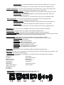
Dimensions (mm)
Accessories
Omega holder (No.99010420)................................2 pcs
Optional accessories
Upgrade kit CRMX Univerzal 260 (No. 9903 0100
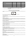
11. Maintenance and cleaning
It is absolutely essential that the fixture is kept clean and that dust, dirt and smoke-fluid residues must not build
up on or within the fixture. Otherwise, the fixture‘s light-output will be significantly reduced. Regular cleaning will
not only ensure the maximum light-output, but will also allow the fixture to function reliably throughout its life.
A soft lint-free cloth moistened with any good glass cleaning fluid is recommended, under no circumstances
should alcohol or solvents be used!
DANGER !
Disconnect from the mains before starting any
maintenance work
The front objective lens will require weekly cleaning as smoke-fluid tends to building up residues, reducing
the light-output very quickly. The cooling-fans should be cleaned monthly.
The interior of the fixture should be cleaned at least annually using a vacuum-cleaner or an air-jet.
Gobo wheels and the internal lenses should be cleaned monthly.
Remove dust and dirt from the fans and cooling vents using a soft brush and vacuum-cleaner.
Important! Check the air filters periodically and clean before they become clogged!
Clean the air filters placed in the fixture´s covers and base. Use a vacuum cleaner, compressed air or you can
wash them and put back dry.
After replacing the air filters, reset the elapsed time counter in the menu "Information" (Information--->Air Filters---> Elapsed Time).
32
Replacing the fuse.
Before replacing the fuse, unplug mains lead.
1) Remove the fuse holder on the rear panel of the base with a fitting screwdriver from the housing
(anti-clockwise).
2) Remove the old fuse from the fuse holder.
3) Install the new fuse in the fuse holder (only the same type and rating).
4) Replace the fuseholder in the housing and fix it.
33
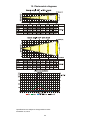
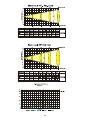
12. Photometric diagrams
Specifications are subject to change without notice.
November 12, 2015
34
35
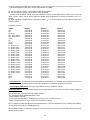
13. ChangeLog
This section summarizes all types of changes in the user manual.
Version of the
manual
Date of issue
Description of changes
1.1
26/05/2014
Added sACN protocol
1.2
8/10/2014
New photometric diagram
36
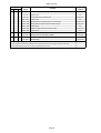
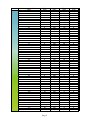
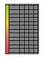
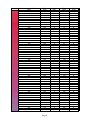
DMX protocol
Robin DLS Profile - DMX protocol - version 1.0
Mode/channel
1
2
3
1
1
1
2
2
*
DMX
Value
4
5
3
4
5
proportional
0 - 255
Fine control of pan movement
0 - 255
Tilt movement by 280°
0 - 255
Fine control of tilt movement
proportional
Tilt
2
proportional
Tilt fine
*
proportional
Pan/Tilt speed , Pan/Tilt time
3
1 - 255
1 - 255
6
Pan movement by 540°
Pan Fine
0
6
Type of
control
Pan
0 - 255
3
Function
Max. speed (tracking mode)
P./T. speed-set Speed Mode in menu: Pan/Tilt Mode
Speed from max. to min. (vector mode)
P./T. time - set Time Mode in menu: Pan/Tilt Mode
Time from 0.1 s to 25.5 sec.
step
proportional
proportional
Power/Special functions
4
0 -9
10-14
15-19
Reserved
To activate following functions, stop in DMX value for at least 3 s
and shutter must be closed at least 3 sec. („Shutter,Strobe”
channel 45/37/35 must be at range: 0-31 DMX). Corresponding
menu items are temporarily overriden).
DMX input: Wired DMX *
DMX input: Wireless DMX *
step
step
* function is active only10 seconds after switching the fixture on
20-24
25-29
30-39
40-49
50 - 59
60 - 69
70 - 79
80 - 89
90-109
110 - 119
120-129
130 - 139
140 - 149
150 - 159
160 - 169
170 - 179
180 - 189
190 - 199
200 - 209
210 - 239
240
241
242 - 255
White point 8000K ON
White point 8000K OFF
RGB colour mixing mode
CMY colour mixing mode
Pan/Tilt speed mode
Pan/Tilt time mode
Blackout while pan/tilt moving
Disabled blackout while pan/tilt moving
Reserved
Blackout while gobo wheel moving
Disabled blackout while gobo wheel moving
To activate following functions, stop in DMX value for at least 3
seconds.
Fixture reset (except pan/tilt)
Pan/Tilt reset
Reserved
Gobo wheel reset
Reserved
Zoom/focus/frost/prism reset
Iris /framing shutters/effect wheel reset
Total fixture reset
Reserved
Disable "Theatre mode"
"Theatre mode" -automatic control of fan noise
"Theatre mode" -fan noise control from min. to max.
Page 1
step
step
step
step
step
step
step
step
step
step
step
step
step
step
step
step
step
step
proportional
DMX protocol
Mode/channel
1
2
3
7
7
DMX
Value
9
10
8
*
9
0 - 255
Red or Cyan colour saturation control - coarse (0-100%)
0 - 255
Red or Cyan colour saturation control - fine
0 - 255
Green or Magenta colour saturation control - coarse (0-100%)
12
10
8
13
*
*
16
12
step
step
step
step
proportional
step
proportional
step
proportional
step
proportional
step
proportional
step
proportional
step
proportional
proportional
proportional
proportional
proportional
Green or Magenta colour saturation control - fine
proportional
Blue or Yellow colour saturation control - coarse (0-100%)
proportional
Blue or Yellow colour saturation control - fine
proportional
White (8 bit)
9
0 - 255
If RGBW mode is selected:
White colour saturation control - coarse (0-100%)
If CMY mode is selected:
No function
0 - 255
White colour saturation control - fine (RGBW mode only)
0-255
*
step
Blue/ Yellow (16bit)***
0 - 255
15
step
Blue/Yellow (8 bit)***
0 - 255
11
step
Green/Magenta (16bit)***
0 - 255
14
step
Green/Magenta (8 bit)***
7
*
step
Red/Cyan (16bit)***
*
*
No function
White 2700 K
White 2700 K (Halogen lamp mode**)
White 3200 K
White 3200 K (Halogen lamp mode**)
White 4200 K
White 5600 K
White 8000 K
Blue (Blue=full, Red+Green+White=0)
Red=0, Green->up,Blue =full, White=0
Light Blue (Red=0, Green=full, Blue =full, White=0)
Red=0, Green=full, Blue->down, White=0
Green (Red=0, Green=full, Blue =0, White=0)
Red->up, Green=full, Blue=0, White=0
Yellow (Red=full, Green=full, Blue=0, White=0)
Red=full, Green->down, Blue=0, White=0
Red(Red=full, Green=0, Blue=0, White=0)
Red=full, Green=0, Blue->up, White=0
Magenta (Red=full, Green=0, Blue=full, White=0)
Red -> down, Green=0, Blue=full, White=0
Blue (Red=0, Green=0, Blue=full, White=0)
Rainbow effect (with fade time)from slow-> fast
Rainbow effect(without fade time) from slow-> fast
Red/Cyan (8 bit)***
6
11
Type of
control
Virtual colour wheel
5
0
1-2
3
4-5
6
7-9
10-12
13-15
16
17-55
56
57 - 95
96
97 – 134
135
136 - 174
175
176 -214
215
216 - 246
247
248-251
252-255
8
Function
proportional
White (16 bit)
*
proportional
CT0
10
If function "White Point 8000K" is ON
0-255
Col. temperature correction from 8000K to 2700K -for whites only
(0=8000K, 64=5600K, 128=4200K, 192=3200K, 0=2700K)
To get colour temperatures stated above, RGBW channels have to
be set at the same value (e.g. 255DMX) or RGB=0 and White
channel > 0 DMX
If function "White Point 8000K" is OFF
Page 2
proportional
DMX protocol
Mode/channel
1
2
3
DMX
Value
0-255
17
13
11
18
14
12
20
15
16
Speed of rot. gobo selection from max. to min. (0-25.5sec.)
0-19
20-127
128-170
171-213
214-255
No function
Proportional indexing (73-center)
Ramping from open to full position ( max--->min. speed)
Ramping from open to half position ( max. --->min. speed)
Ramp. from half position to full position ( max. --->min. speed)
0
1 - 127
128 - 129
130 - 255
No rotation
Forwards rotation from fast to slow
No rotation
Backwards rotation from slow to fast
proportional
step
proportional
proportional
proportional
proportional
Effect wheel rotation
13
step
proportional
step
proportional
Effect wheel animations
14
8-9
10-11
12-13
14-15
16-17
18-19
20-21
22-23
24-25
26-27
28-255
17
proportional
Effect wheel positioning
0-7
21
Colour temperature correction for mixed colours
Type of
control
Speed of rot. Gobo selection
0-255
19
Function
No animation
Note : Set suitable DMX value at Focus channel to get desired
animation. All animations were created at distance 7 m from
screen with zoom=128DMX, Focus value is different for each
effect (focus value is stated in parentheses for this distance)
The channels are blocked: Effect wheel positioning, Effect wheel
rotation
Macro 1 (Focus=152)
Macro 2 (Focus=113)
Macro 3 (Focus=100)
Macro 4 (Focus=105)
Macro 5 (Focus=102)
Macro 6 (Focus=110)
Macro 7 (Focus=108)
Macro 8 (Focus=121)
Macro 9 (Focus=102)
Macro 10 (Focus=98)
Reserved
step
step
step
step
step
step
step
step
step
step
Rotating gobo wheel
15
0-3
4-7
8-11
12-15
16-19
20-23
24-27
28-31
32-35
36-39
40-43
44-47
In the range of 0-59 DMX the gobo selection speed is controlled
by the Effect Speed channel.
Index - set indexing on channel 22/18/16
Open/hole
Gobo 1
Gobo 2
Gobo 3
Gobo 4
Gobo 5
Gobo 6
Gobo 7
Rotation - set rotation on channel 22/18/16
Gobo 1
Gobo 2
Gobo 3
Gobo 4
Page 3
step
step
step
step
step
step
step
step
step
step
step
step
DMX protocol
Mode/channel
1
2
3
DMX
Value
48-51
52-55
56-59
Function
Gobo 5
Gobo 6
Gobo 7
Type of
control
step
step
step
Shaking gobos from slow to fast
60 - 69
70 - 79
80 - 89
90 - 99
100 - 109
110 - 119
120 - 129
Index - set indexing on channel 22/18/16
Gobo 1
Gobo 2
Gobo 3
Gobo 4
Gobo 5
Gobo 6
Gobo 7
proportional
proportional
proportional
proportional
proportional
proportional
proportional
Shaking gobos from slow to fast
130 - 139
140 - 149
150 - 159
160 - 169
170 - 179
180 - 189
190 - 199
200 - 201
202 - 221
222 - 223
224 - 243
244 - 249
250 - 255
22
18
Rotation - set rotation on channel 22/18/16
Gobo 1
Gobo 2
Gobo 3
Gobo 4
Gobo 5
Gobo 6
Gobo 7
Open/hole
Forwards gobo wheel rotation from fast to slow
No rotation
Backwards gobo wheel rotation from slow to fast
Random gobo selection by audio control
(Set microphone sensitivity in menu „Personality”)
Auto random gobo selection from fast to slow
*
19
proportional
proportional
proportional
proportional
proportional
step
proportional
step
proportional
step
proportional
proportional
step
proportional
step
proportional
Rot. gobo indexing/rotation - fine
*
0-255
24
proportional
Rot. gobo indexing and rotation
16
Gobo indexing - set position on channel 21/17/15
0 - 255 Gobo indexing
Gobo rotation - set position on channel 21/17/15
0
No rotation
1 - 127 Forwards gobo rotation from fast to slow
128 - 129 No rotation
130 - 255 Backwards gobo rotation from slow to fast
23
proportional
Fine indexing (rotation)
proportional
Prism
17
0 - 19
20 - 127
128 - 255
128 - 135
136 - 143
144 - 151
152 - 159
160 - 167
168 - 175
176 - 183
184 - 191
Open position (hole)
3-facet rotating prism
Prism/gobo macros
Macro 1
Macro 2
Macro 3
Macro 4
Macro 5
Macro 6
Macro 7
Macro 8
step
step
step
step
step
step
step
step
step
step
Page 4
DMX protocol
Mode/channel
1
2
3
DMX
Value
192 - 199
200 - 207
208 - 215
216 - 223
224 - 231
232 - 239
240 - 247
248 - 255
25
20
21
22
step
step
step
step
step
step
step
step
No rotation
Forwards rotation from fast to slow
No rotation
Backwards rotation from slow to fast
Open
Frost from 0% to 100%
100% frost
Pulse closing from slow to fast
Pulse opening from fast to slow
Ramping from fast to slow
29
*
23
0 - 255
Fine iris movement
0 - 255
Zoom from max. to min.beam angle
*
31
24
22
32
*
*
proportional
proportional
step
proportional
step
proportional
proportional
step
step
step
step
proportional
proportional
Fine zooming
proportional
Focus
0 - 255
Continuous adjustment from far to near
proportional
Focus - fine
0- 255
25
step
proportional
Zoom - fine
0-255
33
step
proportional
Zoom
21
*
proportional
Iris - fine
*
30
step
Iris
20
0
Open
1 - 179 From max.diameter to min.diameter
180 - 191 Closed
Pulse effects with Iris blackout:
192 -219 Pulse opening from slow to fast
220 - 247 Pulse closing from fast to slow
248 - 249 Random pulse opening (fast)
250 - 251 Random pulse opening (slow)
252 - 253 Random pulse closing (fast)
254 - 255 Random pulse closing (slow)
28
step
proportional
Frost
19
0
1 - 179
180 - 189
190 - 211
212 - 233
234 - 255
27
Macro 9
Macro 10
Macro 11
Macro 12
Macro 13
Macro 14
Macro 15
Macro 16
Type of
control
Prism rotation
18
0
1 - 127
128 - 129
130 - 255
26
Function
23
0
1
8
16
24
Fine focusing
Autofocus (priority & distance selection)
Select desired distance and effect on which you need to focus
and use "Focus" channel (31/24/22) to focus the image.
Autofocus Off
Hole and Framing shutters
4 metres
6 metres
8 metres
10 metres
Page 5
proportional
step
proportional
proportional
proportional
proportional
DMX protocol
Mode/channel
1
2
3
DMX
Value
32
40
48
56
64
72
80
88
96
104
112
120
121-255
34
26
24
0-127
128
129-255
35
27
25
36
28
26
0-255
0-127
128
129-255
37
29
27
0-255
38
30
28
0-127
128
129-255
39
31
29
40
32
30
0-255
0-127
128
129-255
41
33
31
0-255
42
34
32
0-127
128
129-255
43
35
33
0-3
4-7
8-11
12-15
16-19
20-23
24-27
Function
12 metres
14 metres
16 metres
18 metres
Rotating gobo wheel
4 metres
6 metres
8 metres
10 metres
12 metres
14 metres
16 metres
18 metres
Reserved
Framing shutters module rotation
Rotation from left to center
Center
Rotation from center to right
Framing shutter 1- movent
Movement from Outward to Inward
Framing shutter 1- swivelling
Swivelling from -25 degrees towards 0 degrees
0 degrees (default)
Swivelling from 0 degrees to +25 degrees
Framing shutter 2- movent
Movement from Outward to Inward
Framing shutter 2- swivelling
Swivelling from -25 degrees towards 0 degrees
0 degrees (default)
Swivelling from 0 degrees to +25 degrees
Framing shutter 3 movent
Movement from Outward to Inward
Framing shutter 3- swivelling
Swivelling from -25 degrees towards 0 degrees
0 degrees (default)
Swivelling from 0 degrees to +25 degrees
Framing shutter 4 movent
Movement from Outward to Inward
Framing shutter 4- swivelling
Swivelling from -25 degrees towards 0 degrees
0 degrees (default)
Swivelling from 0 degrees to +25 degrees
Framing shutters macros
No function
Macro 1
Macro 2
Macro 3
Macro 4
Macro 5
Macro 6
Type of
control
proportional
proportional
proportional
proportional
proportional
proportional
proportional
proportional
proportional
proportional
proportional
proportional
proportional
step
proportional
proportional
proportional
step
proportional
proportional
proportional
step
proportional
proportional
proportional
step
proportional
proportional
proportional
step
proportional
step
step
step
step
step
step
Page 6
DMX protocol
Mode/channel
1
2
3
DMX
Value
28-31
32-35
36-39
40-43
44-47
48-51
52-55
56-59
60-63
64-67
68-71
72-75
76-79
80-83
84-87
88-91
92-95
96-99
100-103
104-107
108-111
112-115
116-119
120-123
124-127
128-131
132-135
136-139
140-143
144-147
148-151
152-155
156-159
160-163
164-167
168-171
172-175
176-179
180-183
184-187
188-191
192-195
196-199
200-203
204-207
208-211
212-255
44
36
34
45
37
35
0- 255
Function
Macro 7
Macro 8
Macro 9
Macro 10
Macro 11
Macro 12
Macro 13
Macro 14
Macro 15
Macro 16
Macro 17
Macro 18
Macro 19
Macro 20
Macro 21
Macro 22
Macro 23
Macro 24
Macro 25
Macro 26
Macro 27
Macro 28
Macro 29
Macro 30
Macro 31
Macro 32
Macro 33
Macro 34
Macro 35
Macro 36
Macro 37
Macro 38
Macro 39
Macro 40
Macro 41
Macro 42
Macro 43
Macro 44
Macro 45
Macro 46
Macro 47
Macro 48
Macro 49
Macro 50
Macro 51
Macro 52
Reserved
Framing shutters macro speed
Speed from slow to fast.
Type of
control
step
step
step
step
step
step
step
step
step
step
step
step
step
step
step
step
step
step
step
step
step
step
step
step
step
step
step
step
step
step
step
step
step
step
step
step
step
step
step
step
step
step
step
step
step
step
proportional
Shutter/ strobe
Page 7
DMX protocol
Mode/channel
1
2
3
DMX
Value
0 - 31
32 - 63
64 - 95
96 - 127
128 - 143
144 - 159
160 - 191
192 - 223
224 - 255
46
47
38
*
Function
Shutter closed
Shutter open
Strobe-effect from slow to fast
Shutter open
Opening pulse in sequences from slow to fast
Closing pulse in sequences from fast to slow
Shutter open
Random strobe-effect from slow to fast
Shutter open
Type of
control
step
step
proportional
step
proportional
proportional
step
proportional
step
Dimmer intensity
36
0 - 255
Dimmer intensity from 0% to 100%
0 - 255
Fine dimming
proportional
Dimmer intensity - fine
*
proportional
** In the Halogen lamp mode the Dimmer channel imitates behaviour of the halogen lamp during dimming
*** Select RGB or CMY mixing mode on channel "Power/Special functions"
Page 8
Virtual colour wheel - colour mixing chart
Scale*
Virtual Colour Wheel
DMX
Theatre mode off
1-3 (White 2700K)
4-6 (White 3200K)
7-9 (White 4200K)
10-12 (White 5600K)
13-15 (White 8000K)
Theatre mode on
1-3 (White 2700K)
4-6 (White 3200K)
7-9 (White 4200K)
10-12 (White 5600K)
13-15 (White 8000K)
16
17
18
19
20
21
22
23
24
25
26
27
28
29
30
31
32
33
34
35
36
37
38
39
40
41
42
43
44
45
46
47
48
49
50
51
52
53
54
55
56
57
58
Red
DMX
Green
DMX
Blue
DMX
White
DMX
255
255
249
165
172
176
201
243
255
255
8
12
28
36
65
20
100
200
255
255
255
255
248
209
171
0
0
0
0
0
0
0
0
0
0
0
0
0
0
0
0
0
0
0
0
0
0
0
0
0
0
0
0
0
0
0
0
0
0
0
0
0
0
0
0
0
0
0
176
201
253
255
255
0
3
6
9
12
15
18
21
24
27
30
36
41
46
52
58
64
68
74
80
86
92
98
104
110
119
129
138
147
156
165
174
183
192
201
210
219
228
237
246
255
255
255
8
12
31
46
61
255
255
255
255
255
255
255
255
255
255
255
255
255
255
255
255
255
255
255
255
255
255
255
255
255
255
255
255
255
255
255
255
255
255
255
255
255
255
255
255
255
246
237
20
100
35
63
61
0
0
0
0
0
0
0
0
0
0
0
0
0
0
0
0
0
0
0
0
0
0
0
0
0
0
0
0
0
0
0
0
0
0
0
0
0
0
0
0
0
0
0
Page 1
Scale*
Virtual Colour Wheel
DMX
59
60
61
62
63
64
65
66
67
68
69
70
71
72
73
74
75
76
77
78
79
80
81
82
83
84
82
86
87
88
89
90
91
92
93
94
95
96
97
98
99
100
101
102
103
104
105
106
107
108
109
110
111
112
113
114
Red
DMX
0
0
0
0
0
0
0
0
0
0
0
0
0
0
0
0
0
0
0
0
0
0
0
0
0
0
0
0
0
0
0
0
0
0
0
0
0
0
3
6
9
12
15
18
21
24
27
30
36
41
46
52
58
64
68
74
Page 2
Green
DMX
255
255
255
255
255
255
255
255
255
255
255
255
255
255
255
255
255
255
255
255
255
255
255
255
255
255
255
255
255
255
255
255
255
255
255
255
255
255
255
255
255
255
255
255
255
255
255
255
255
255
255
255
255
255
255
255
Blue
DMX
228
219
210
201
192
183
174
165
156
147
138
129
119
110
104
98
92
86
80
74
68
64
58
52
46
41
36
30
27
24
21
18
15
12
9
6
3
0
0
0
0
0
0
0
0
0
0
0
0
0
0
0
0
0
0
0
White
DMX
0
0
0
0
0
0
0
0
0
0
0
0
0
0
0
0
0
0
0
0
0
0
0
0
0
0
0
0
0
0
0
0
0
0
0
0
0
0
0
0
0
0
0
0
0
0
0
0
0
0
0
0
0
0
0
0
Scale*
Virtual Colour Wheel
DMX
115
116
117
118
119
120
121
122
123
124
125
126
127
128
129
130
131
132
133
134
135
136
137
138
139
140
141
142
143
144
145
146
147
148
149
150
151
152
153
154
155
156
157
158
159
160
161
162
163
164
165
166
167
168
169
170
Red
DMX
80
86
92
98
104
110
119
129
138
147
156
165
174
183
192
201
210
219
228
240
255
255
255
255
255
255
255
255
255
255
255
255
255
255
255
255
255
255
255
255
255
255
255
255
255
255
255
255
255
255
255
255
255
255
255
255
Page 3
Green
DMX
255
255
255
255
255
255
255
255
255
255
255
255
255
255
255
255
255
255
255
255
255
246
237
228
219
210
201
192
183
174
165
156
147
138
129
119
110
104
98
92
86
80
74
68
64
58
52
46
41
36
30
27
24
21
18
15
Blue
DMX
0
0
0
0
0
0
0
0
0
0
0
0
0
0
0
0
0
0
0
0
0
0
0
0
0
0
0
0
0
0
0
0
0
0
0
0
0
0
0
0
0
0
0
0
0
0
0
0
0
0
0
0
0
0
0
0
White
DMX
0
0
0
0
0
0
0
0
0
0
0
0
0
0
0
0
0
0
0
0
0
0
0
0
0
0
0
0
0
0
0
0
0
0
0
0
0
0
0
0
0
0
0
0
0
0
0
0
0
0
0
0
0
0
0
0
Scale*
Virtual Colour Wheel
DMX
171
172
173
174
175
176
177
178
179
180
181
182
183
184
185
186
187
188
189
190
191
192
193
194
195
196
197
198
199
200
201
202
203
204
205
206
207
208
209
210
211
212
213
214
215
216
217
218
219
220
221
222
223
224
225
226
Red
DMX
255
255
255
255
255
255
255
255
255
255
255
255
255
255
255
255
255
255
255
255
255
255
255
255
255
255
255
255
255
255
255
255
255
255
255
255
255
255
255
255
255
255
255
255
255
246
237
228
219
210
201
192
183
174
165
156
Page 4
Green
DMX
12
9
6
3
0
0
0
0
0
0
0
0
0
0
0
0
0
0
0
0
0
0
0
0
0
0
0
0
0
0
0
0
0
0
0
0
0
0
0
0
0
0
0
0
0
0
0
0
0
0
0
0
0
0
0
0
Blue
DMX
0
0
0
0
0
3
6
9
12
15
18
21
24
27
30
36
41
46
52
58
64
68
74
80
86
92
98
104
110
119
129
138
147
156
165
174
183
192
201
210
219
228
237
246
255
255
255
255
255
255
255
255
255
255
255
255
White
DMX
0
0
0
0
0
0
0
0
0
0
0
0
0
0
0
0
0
0
0
0
0
0
0
0
0
0
0
0
0
0
0
0
0
0
0
0
0
0
0
0
0
0
0
0
0
0
0
0
0
0
0
0
0
0
0
0
Scale*
Virtual Colour Wheel
DMX
227
228
229
230
231
232
233
234
235
236
237
238
239
240
241
242
243
244
245
246
247
248-255 (Rainbow effect)
Red
DMX
147
138
129
119
110
104
98
91
84
77
70
63
56
49
42
35
28
21
14
7
0
****
* Colour scale as an illustration only
Page 5
Green
DMX
0
0
0
0
0
0
0
0
0
0
0
0
0
0
0
0
0
0
0
0
0
****
Blue
DMX
255
255
255
255
255
255
255
255
255
255
255
255
255
255
255
255
255
255
255
255
255
****
White
DMX
0
0
0
0
0
0
0
0
0
0
0
0
0
0
0
0
0
0
0
0
0
****