1
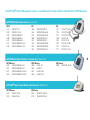
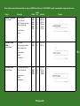
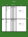
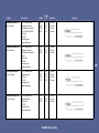
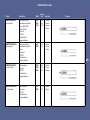
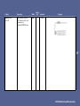
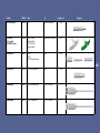
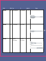
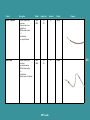
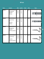
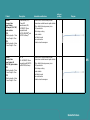
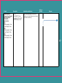
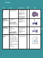
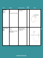
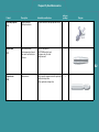
CRM Product Guide
Pacing, Defibrillation, and Cardiac Resynchronization Therapy
December 2008
Dielines do not print
Pacing Pulse Generators
Pacemakers..................................................................................................................................................5
Defibrillation Pulse Generators
Implantable Cardioverter Defibrillators (ICDs)..................................................................................7
Cardiac Resynchronization Therapy Pulse Generators
Cardiac Resynchronization Therapy Defibrillators (CRT-Ds)......................................................11
Cardiac Resynchronization Therapy Pacemakers (CRT-Ps)..................................................17
Pacing Leads and Accessories
Pacing Leads..............................................................................................................................................19
Pacing Lead Accessories.......................................................................................................................21
Pacing Lead Stylets.................................................................................................................................23
Defibrillation Leads and Accessories
Defibrillation Leads..................................................................................................................................25
Defibrillation Lead Accessories...........................................................................................................27
Defibrillation Lead Stylets.....................................................................................................................31
Cardiac Resynchronization Therapy Leads and Accessories
CRT Leads.......................................................................................................................................... 33
Guide Catheters............................................................................................................................... 35
Guide Wires.......................................................................................................................................41
Finishing Wires................................................................................................................................ 46
LV-1 Accessories............................................................................................................................. 48
IS-1 Accessories.............................................................................................................................. 50
Frequently Used Accessories....................................................................................................... 52
Other Accessories........................................................................................................................... 54
Compatibility Charts....................................................................................................................... 56
Dielines do not print
The LATITUDE® Patient Management system is compatible with virtually all Boston Scientific ICD and CRT-D devices.
LATITUDE Wanded Communicator (Model 6481)
CRT-D
H115
H119
H135
H170
H175
H177
H179
CONTAK® CD 2
CONTAK CD 2 HE
CONTAK RENEWAL®
CONTAK RENEWAL 3
CONTAK RENEWAL 3
CONTAK RENEWAL 3 HE
CONTAK RENEWAL 3 HE
ICD
1850
1852
1857
1860
1851
1853
1858
1861
VENTAK PRIZM® VR
VENTAK PRIZM VR HE
VENTAK PRIZM VR HE
VENTAK PRIZM 2 VR
VENTAK PRIZM DR
VENTAK PRIZM DR HE
VENTAK PRIZM DR HE
VENTAK PRIZM 2 DR
ICD
T135
T125
T127
T180
T165
T167
T175
T177
VITALITY® DS VR
VITALITY DS DR
VITALITY EL DR
VITALITY HE
VITALITY 2 DR
VITALITY 2 EL DR
VITALITY 2 VR
VITALITY 2 EL VR
LATITUDE Push Button Wireless Communicator (Model 6482)
CRT-D Wireless
H210
CONTAK RENEWAL 3 RF
H215
CONTAK RENEWAL 3 RF
H217
CONTAK RENEWAL 3 RF HE
H219
CONTAK RENEWAL 3 RF HE
CRT-D Wireless
H220
LIVIAN RF
H225
LIVIAN RF
H227
LIVIAN RF HE
H229
LIVIAN RF HE
TM
LATITUDE® Touch Screen Wireless Communicator (Model 6476)
CRT-D Wireless
N118
COGNIS RF HE
N119
COGNIS RF HE
TM
ICD Wireless
E102
TELIGEN VR RF HE
E110
TELIGEN DR RF HE
TM
4
ICD Wireless
E030
CONFIENT RF HE
TM
Model
Type
Longevity
(years)
Volume
(cc)
Thickness
(mm)
Header
-AV Delay extendable to 400 ms
-M V Blended Sensor
-S tored Onset EGMs
-A utomatic Capture
-AV Search Hysteresis
-A utoLifestyle ®
-Ventricular Rate Regulation
-Sudden Brady Response
S601
S602
S603
S606
SR
DR
DR
DR
8.6 1
8.8 1
6.51
8.8 1
10.0
12.6
10.8
12.6
8
8
8
8
IS-1
3.2 mm/IS-1 compatible
IS-1
IS-1
-M V Blended Sensor
-S tored Onset EGMs
-AV Search Hysteresis
-Ventricular Rate Regulation
-Sudden Brady Response
S401
S403
S404
SR
DR
DR
7.7 2
5.9 2
8.12
10.0
10.8
12.6
8
8
8
IS-1
IS-1
IS-1
-S tored Onset EGMs
-Accelerometer Sensor
-D ynamic AV Delay
-Sudden Brady Response
S201
S203
S204
S205
S208
Product
Description
ALTRUA™ 60
ALTRUA 40
ALTRUA 20
Diagram
5
SR
DR
SR
DR
DR
9.6 3
7.13
9.6 3
9.7 3
9.7 3
10.1
10.8
11.0
14.9
12.6
8
8
8
8
8
3.2 mm/IS-1 compatible
IS-1
5/6 mm
5/6 mm
IS-1
1 L ongevity projections as described in device user manual. Settings: 60 ppm, A=2.5 V, V=1.0 V, 500 ohms, 100% paced, MV Blended Sensor ON, Onset EGMs ON, Automatic Capture ON.
2 L ongevity projection as described in user manual. Settings: 60 ppm, A=2.5 V, V=2.5 V, 500 ohms, 100% paced, MV Blended Sensor ON, Onset EGMS ON.
3 L ongevity projection as described in user manual. Settings: 60 ppm, A=2.5 V, V=2.5 V, 500 ohms, 100% paced, Accelerometer Sensor ON, Onset EGMS ON.
Pacemakers
Dielines do not print
Dielines do not print
Model
Type
Energy
(J)
Warranty
(years)
Volume
(cc)
Thickness
(mm)
Header
-Safety Core™ and Safety Architecture
-Q uick Convert ™
-Rhythm ID ® and OBDE in the
same device
-2 -zone nominals
-AV Search + (up to 400 ms)
-L i MnO 2 battery for extended
longevity* and fast, consistent
charge times over the life of the
device
-Programmable shock vectors
-Indications-based programming
-Respiratory rate trend
-17 minutes of EGM storage,
3 channels on
-Ventricular Rate Regulation
E102
E110
VR
DR
41
41
7
31.5
31.5
9.9
9.9
DF-1/IS-1
DF-1/IS-1
-4 00 ms AV Delay
-AV Search Hysteresis
-C ompatible with LATITUDE
Patient Management System
-S tored EGMs w/Onset
-Ventricular Rate Regulation
-Advanced battery technology
E030
Product
Description
TELIGEN™
CONFIENT™
-
7
DR
41
*As compared with previous Boston Scientific devices
Dielines do not print
Diagram
ICDs
5
44
14.5
DF-1/IS-1
Dielines do not print
ICDs
Model
Type
Energy
(J)
Warranty
(years)
Volume
(cc)
Thickness
(mm)
-R hythm ID
-AV Search Hysteresis (DR only)
-Ventricular Rate Regulation
-F ullView ™ Stored EGMs w/Onset
-Interval Graph
-My Patient Profile with
Quick Profiles ™
T165
T175
DR
VR
31
31
5
5
30
30
11
DF-1/IS-1
DF-1/IS-1
-R hythm ID
-AV Search Hysteresis (DR only)
-Ventricular Rate Regulation
-FullView Stored EGMs w/Onset
-Interval Graph
-M y Patient Profile with
Quick Profiles
T167
T177
DR
VR
31
31
7
7
35
35
11
DF-1/IS-1
DF-1/IS-1
-A utomatic Atrial ATP
-A trial Rhythm Classification
-A trial Pacing Preference
-C ardioversion
-ProACt
-Ventricular Rate Regulation
-AV Search Hysteresis
-FullView Stored EGMs w/Onset
-Shock If Unstable
-M y Patient Profile
A155
Product
Description
VITALITY® 2
VITALITY 2 EL
VITALITY AVT®
Header
Diagram
8
DR
31
5
30
11
DF-1/IS-1
Model
Type
Energy
(J)
Warranty
(years)
Volume
(cc)
Thickness
(mm)
Header
-AV Search Hysteresis
-F ullView Stored EGMs w/Onset
-Daily Measurements
-Shock If Unstable
-Patient-triggered Monitor
T125
T135
DR
VR
31
31
5
5
30
30
11
DF-1/IS-1
-AV Search Hysteresis
-F ullView Stored EGMs w/Onset
-Daily Measurements
-Shock If Unstable
-Patient-triggered Monitor
T127
DR
31
7
35
11
DF-1/IS-1
-AV Search Hysteresis (DR only)
-E nergy-efficient Episode Onset
-3 -channel Stored EGMs
(DR only)
-Shock If Unstable
1852
1853
1857
1858
Product
Description
VITALITY DS
VITALITY EL
VENTAK PRIZM ® HE
Dielines do not print
Diagram
9
VR
DR
VR
DR
41
41
41
41
4
4
4
4
38
39
43
45
15
15
15
15
DF-1/IS-1
DF-1/IS-1
6.1 mm/4.75 mm
6.1 mm/4.75 mm
IS-1 atrial
Dielines do not print
Product
Description
COGNIS™
-Safety Core and Safety
Architecture
-Quick Convert
-SmartDelay™ algorithm for
quick AV delay programming
recommendations intended to
provide optimally timed CRT
-Electronic Repositioning™
with 6 configurations with
bipolar leads
-BiV Trigger and VRR
-Rhythm ID and OBDE in the
same device
-Programmable shock vectors
-L i MnO 2 battery for extended
longevity* and fast, consistent
charge times over the life of
the device
-Respiratory rate trend
-2-zone nominals
-Indications-based
programming
-17 minutes of EGM storage,
3 channels on
Model
Energy
(J)
Warranty
(years)
Volume
(cc)
Thickness
(mm)
Header
N118
N119
41
41
5
5
32.5
32.5
9.9
9.9
IS-1/DF-1:LV-1
IS-1/DF-1:IS-1
Diagram
11
*As compared with previous Boston Scientific devices
Dielines do not print
CRT-Ds
Dielines do not print
CRT-Ds
Product
Description
LIVIAN™
-SmartDelay algorithm for
quick AV delay programming
recommendations intended to
provide optimally timed CRT
-BiV Trigger and VRR
-C ompatible with LATITUDE
Patient Management System
-E lectronic Repositioning
-S tored EGMs with Onset
-A dvanced battery technology
LIVIAN HE
Model
Energy
(J)
Warranty
(years)
Volume
(cc)
Thickness
(mm)
Header
H220
H225
31
31
4
40
40
14.5
14.5
IS-1
IS-1/LV-1
H227
H229
41
41
4
44
44
14.5
14.5
IS-1
IS-1/LV-1
Diagram
12
Product
Description
CONTAK RENEWAL 3
®
CONTAK RENEWAL 3 HE
-Independent channels for right
and left ventricular pacing
and sensing
-Patient-centric diagnostics:
-HRV Monitor Footprint
-ABM
-HRV Monitor Trending
-Activity Log
-High-energy output
-VRR
-Fast charge time
-Daily measurements
Model
Energy
(J)
Warranty
(years)
Volume
(cc)
Thickness
(mm)
Header
H170
H175
31
31
3+2
37
37
11.5
11.5
IS-1
LV-1
H177
H179
41
41
3+1
40
40
11.5
11.5
IS-1
LV-1
Diagram
13
Dielines do not print
Product
Description
CONTAK RENEWAL 3 RF
-Independent channels for right
and left ventricular pacing and
sensing
-Patient-centric diagnostics:
-Patient-triggered monitor
-Heart rate variability (HRV)
Monitor Footprint
-Automatic Balance Monitor
(ABM)
-HRV Monitor Trending
-Activity Log
-Snapshot viewer
-Ventricular Rate Regulation
-Fast charge time
-Daily measurements
-Enhanced telemetry
communication with ZIP™
wandless telemetry
CONTAK RENEWAL 3 RF HE
Dielines do not print
Model
Energy
(J)
Warranty
(years)
Volume
(cc)
Thickness
(mm)
Header
H210
H215
31
31
3+2
39
39
14
14
IS-1
LV-1
H217
H219
41
41
3+1
43
43
14
14
IS-1
LV-1
Diagram
14
Product
Description
CONTAK RENEWAL
-Independent channels for right
and left ventricular pacing and
sensing
-Patient-centric diagnostics:
-Heart rate variability (HRV)
Monitor Footprint
-HRV Monitor Trending
-Activity Log
-Ventricular Rate Regulation
Model
Energy
(J)
Warranty
(years)
Volume
(cc)
Thickness
(mm)
Header
H135
31
3+2
45
15
LV-1
Diagram
15
Dielines do not print
Dielines do not print
Product
Description
CONTAK RENEWAL TR
-Independent channels for
right and left ventricular
pacing and sensing
-Patient-centric diagnostics:
-Heart rate variability (HRV)
Monitor Footprint
-HRV Monitor Trending
-Activity Log
-Ventricular Rate Regulation
-Daily measurements
-110 sec EGM storage
Model
H120
H125
Warranty
(years)
Volume
(cc)
Thickness
(mm)
Header
5
14
14
8.5
8.5
IS-1
LV-1
Diagram
17
CRT-Ps
Dielines do not print
Dielines do not print
Due to variations among introducer manufacturers, please call CRM Technical Services at 1.800.CARDIAC for specific recommendations regarding introducer sizes
Product
Description
Model
Length
(cm)
Insulation
FINELINE II STEROX EZ
Active Fixation
-4 turns (55D poly),
-6 turns (silicone)
-IROX ® -coated tip electrode
-T hin co-radial design -IS-1
-S teroid elution
-Bipolar
4469
4470
4471
4472
4473
4474
45
52
58
45
52
58
55D Poly
55D Poly
55D Poly
Silicone
Silicone
Silicone
FINELINE II STEROX
Atrial-J
Passive Fixation
-Preformed J
-IROX-coated tip electrode
-T hin co-radial design
-IS-1
-S teroid elution
-Bipolar
-T ined fixation
4479
4480
45
52
55D Poly
55D Poly
-IROX-coated tip electrode
-T hin co-radial design
-IS-1
-S teroid elution
-Bipolar
-T ined fixation
4456
4457
4458
4459
®
FINELINE II STEROX
Passive Fixation
Dielines do not print
Diagram
19
52
58
52
58
55D Poly
55D Poly
Silicone
Silicone
Pacing Leads
Dielines do not print
Pacing Leads
Model
Length
(cm)
Insulation
-E xtendable/retractable
-8 turns (minimum)
-Iridium-coated tip electrode
-IS-1
-S teroid elution
-Bipolar
4135
4136
4137
45
53
60
Silicone
Silicone
Silicone
-E xtendable/retractable
-6 –8 turns
-IS-1
-S teroid elution
-Bipolar
4086
4087
4088
45
52
59
Silicone
Silicone
Silicone
Product
Description
DEXTRUS™
Active Fixation
FLEXTEND ®
Active Fixation
Diagram
20
Product
From
To
Lead Adapter Sleeve
6016
(1) 3.2 mm low-profile or
IS-1 unipolar connector
(1) 5 mm
unipolar terminal
Lead Adapter
6017
(1) 3.2 mm low-profile or
IS-1 bipolar connector
(1) 4.75 mm bifurcated
bipolar terminal
16
Lead Adapter
6018
(1) 6.1 mm
unipolar connector
(1) 3.2 mm low-profile
unipolar terminal
15
Lead Adapter
6020
(1) 4.75 mm
unipolar connector
(1) 3.2 mm low-profile
unipolar terminal
15
Lead Adapter Sleeve
6022
(1) 3.2 mm low-profile
or IS-1 connector
(1) 6 mm
unipolar terminal
Lead Adapter
(Uses 2-unipolar4.75 mm
or 1-Bif. Bipolar 4.75 mm)
6024
(2) 4.75 mm connectors
(1) IS-1 bipolar
terminal
Dielines do not print
Model
Length (cm)
Diagram
N/A
21
N/A
16
Pacing Lead Accessories
Dielines do not print
Product
Pacing Lead Accessories
Model
From
To
Length (cm)
Lead Cap Kit
6504
(2) 3.2 mm or
(2) 4.75 mm connectors
N/A
N/A
Lead Adapter Sleeve
6526
(2) 4.75 mm connectors
(1) 6 mm terminal
N/A
Lead Cap Kit
6811
(2) 4.75 mm connectors
N/A
N/A
Lead Adapter
6986
(1) IS-1 or 3.2 mm
low-profile bipolar connector
(1) IS-1 bipolar
terminal
14
Lead Extender/Adapter
6987
(1) IS-1 or 3.2 mm
low-profile bipolar connector
(1) IS-1 bipolar
terminal
45
IS-1 Port Plug (1)
6998
N/A
(2) IS-1 terminals
N/A
Diagram
22
Pacing Stylets
Type
Wide
Atrial J
Wide
Atrial J
Wide
Atrial J
Wide
Atrial J
Wide
Atrial J
Wide
Atrial J
Length
Diameter
(cm) Firmness
(in)
Model Knob Color Cap Color
Type
Length
Diameter
(cm) Firmness
(in)
Model Knob Color Cap Color
45
Soft
0.014
6053
Green
White
Straight
52
Firm
0.016
6583
White
Red
45
Firm
0.016
6057
White
White
Straight
52
Soft
0.014
6585
Green
Red
52
Soft
0.014
6054
Green
Red
Straight
59
Soft
0.014
6601
Green
Yellow
52
Firm
0.016
6058
White
Red
Straight
59
Firm
0.016
6602
White
Yellow
59
Soft
0.014
6055
Green
Yellow
Atrial J
45
Soft
0.014
6506
Green
White
59
Firm
0.016
6059
White
Yellow
Atrial J
45
Firm
0.016
6508
White
White
Straight
45
Soft
0.014
6505
Green
White
Atrial J
52
Firm
0.016
6584
White
Red
Straight
45
Firm
0.016
6507
White
White
Atrial J
59
Soft
0.014
6603
Green
Yellow
Straight
52
Soft
0.014
6585
Green
Red
Atrial J
59
Firm
0.016
6604
White
Yellow
Pacing Lead Stylets
Dielines do not print
23
Pacing Lead Stylets
Dielines do not print
FINELINE Stylets
Type
Length
Diameter
(cm) Firmness
(in)
Model
Knob
Color
Cap Color
Type
Yellow
Yellow
Atrial J
58
Soft
0.013
Length
Diameter
(cm) Firmness
(in)
Model Knob Color Cap Color
Tapered
45
Soft
0.013
6044
Tapered
45
Limber
0.014
6032
Green
Yellow
Atrial J
58
Limber
0.014
Tapered
45
Firm
0.016
6035
White
Yellow
Atrial J
58
Firm
0.016
Tapered
52
Soft
0.013
6045
Yellow
Mint
Straight
45
Soft
0.013
6047
Yellow
Purple
6040
Green
Purple
6043
White
Purple
Yellow
Yellow
6052
Tapered
52
Limber
0.014
6033
Green
Mint
Straight
45
Limber
0.014
6061
Green
Yellow
Tapered
52
Firm
0.016
6036
White
Mint
Straight
45
Firm
0.016
6064
White
Yellow
Tapered
58
Soft
0.013
6046
Yellow
Purple
Straight
52
Soft
0.013
6048
Yellow
Mint
Tapered
58
Limber
0.014
6034
Green
Purple
Straight
52
Limber
0.014
6062
Green
Mint
Tapered
58
Firm
0.016
6037
White
Purple
Straight
52
Firm
0.016
6065
White
Mint
Atrial J
45
Soft
0.013
6050
Yellow
Yellow
Straight
58
Soft
0.013
6049
Yellow
Purple
Atrial J
45
Limber
0.014
6038
Green
Yellow
Straight
58
Limber
0.014
6063
Green
Purple
Atrial J
45
Firm
0.016
6041
White
Yellow
Straight
58
Firm
0.016
6066
White
Purple
Atrial J
52
Soft
0.013
6051
Yellow
Mint
Atrial J
52
Limber
0.014
6039
Green
Mint
Atrial J
52
Firm
0.016
6042
White
Mint
24
Product
Description
Model
Length
(cm)
Insulation
ENDOTAK RELIANCE G
Active Fixation
-ePTFE-covered coils
-Terminal pin-driven
-E xtendable/retractable
-8 Turns (10 turns(0187))
-Dual-coil
-DF-1/IS-1
-S teroid elution
-Integrated bipolar
0184
0185
0186
0187
59
64
70
90
Silicone
Silicone
Silicone
Silicone
ENDOTAK RELIANCE SG
Active Fixation
-ePTFE-covered coil
-Terminal Pin-driven
-E xtendable/retractable
-8 turns
-Single-coil
-DF-1/IS-1
-S teroid elution
-Integrated bipolar
0180
0181
0182
59
64
70
Silicone
Silicone
Silicone
ENDOTAK RELIANCE G
Passive Fixation
-ePTFE-covered coils
-High Impedance
-Dual-coil
-DF-1/IS-1
-S teroid elution
-Integrated bipolar
0174
0175
0176
0177
59
64
70
90
Silicone
Silicone
Silicone
Silicone
ENDOTAK RELIANCE SG
Passive Fixation
-ePTFE-covered coil
-High Impedance
-Single-coil
-DF-1/IS-1
-S teroid elution
-Integrated bipolar
0170
0171
0172
59
64
70
Silicone
Silicone
Silicone
®
Dielines do not print
Diagram
25
Defibrillation Leads
Dielines do not print
Defibrillation Leads
Model
Length
(cm)
-Terminal pin-driven
-E xtendable/retractable
-8 turns (0157, 0158)
-10 turns (0159)
-Dual-coil
-DF-1/IS-1
-S teroid elution
-Integrated bipolar
0157
0158
0159
59
64
90
Silicone
Silicone
Silicone
Silicone
-Terminal pin-driven
-E xtendable/retractable
-8 turns
-Single-coil
-DF-1/IS-1
-S teroid elution
-Integrated bipolar
0137
0138
59
64
Silicone
Silicone
Silicone
ENDOTAK RELIANCE
Passive Fixation
-High Impedance
-Dual-coil
-DF-1/IS-1
-S teroid elution
-Integrated bipolar
0147
0148
0149
59
64
90
Silicone
Silicone
Silicone
ENDOTAK RELIANCE S
Passive Fixation
-High Impedance
-Single-coil
-DF-1/IS-1
-S teroid elution
-Integrated bipolar
0127
0128
59
64
Silicone
Silicone
Product
Description
ENDOTAK RELIANCE
Active Fixation
ENDOTAK RELIANCE S
Active Fixation
Insulation
Diagram
26
Product
Description
ENDOTAK SQ
Array XP
®
-Subcutaneous lead array
-DF-1 with built-in DF-1 port
-3 common coils
-Used with ENDOTAK leads
Model
Length
(cm)
Insulation
0085
70
Silicone
Diagram
27
Dielines do not print
Defibrillation Lead Accessories
Dielines do not print
Product
Model
From
To
DF-1 Port Plug (1)
6996
N/A
(2) DF-1 terminals
Length (cm)
N/A
TVI Tool Kit
(For use with
Reliance G leads)
7600
(1) 9F TVI tool
(white handle)
(1) 11F TVI tool
(green handle)
Hemostatic introducer
N/A
Lead Cap Kit
6623
(2) DF-1
(2) IS-1
(2) 4.75 mm connectors
N/A
N/A
Lead Cap Kit
6810
(2) 6.1 mm connectors
N/A
N/A
Lead Adapter
6833
(2) 6.1 mm connectors
(1) DF-1 terminal
15
Lead Adapter
6835
(2) DF-1 connectors
(1) DF-1 terminal
15
Diagram
28
Product
From
To
Lead Adapter
Model
6836
(2) 6.1 mm connectors
(1) 6.1 mm terminal
Length (cm)
15
Lead Adapter
6931
(1) 6.1 mm connector
(1) DF-1 terminal
14
Diagram
29
Lead Adapter
Dielines do not print
6952
(2) DF-1 and
(1) IS-1 connectors
(2) DF-1 and
(1) IS-1 terminals
60
Dielines do not print
Defibrillation Stylets
Model Length (cm)
Type
Firmness
Diameter
(in)
Knob Color Cap Color
6601
59
Straight
Soft
0.014
Green
Yellow
6602
59
Straight
Firm
0.016
White
Yellow
6771
90
Straight
Firm
0.016
White
Orange
6772
90
Straight
Soft
0.014
Green
Orange
6826
100
Straight
Firm
0.016
White
White
6828
100
Straight
Soft
0.014
Green
White
6963
70
Straight
Firm
0.016
White
Black
6964
70
Straight
Soft
0.014
Green
Black
6971
64
Straight
Firm
0.016
White
Green
6972
64
Straight
Soft
0.014
Green
Green
Defibrillation Lead Stylets
31
Dielines do not print
Dielines do not print
Product
Description
Model
Length (cm)
Terminal
Polarity
ACUITY™ Steerable
-Coronary venous pace/
sense lead
-Either over-the-wire or
stylet delivery
-IROX electrode coating
-IS-1
-Steroid elution
-Pre-shaped J fixation
4554
80
IS-1
Bipolar
4555
90
-Coronary venous pace/
sense lead
-Over-the-wire design
-IROX electrode coating
-IS-1
-Steroid elution
-3-dimensional, spiral fixation
4591
80
IS-1
Unipolar
4592
90
ACUITY Spiral
Dielines do not print
CRT Leads
Diagram
33
Dielines do not print
CRT Leads
Product
Description
EASYTRAK® 2
EASYTRAK 2
EASYTRAK 3
EASYTRAK 3
Model
Length (cm)
Terminal
Polarity
-Coronary venous pacing lead
-Over-the-wire design
-Steriod elution
-Tined fixation
4517
80
LV-1
Bipolar
4518
90
4520
100
-Coronary venous pacing lead
-Over-the-wire design
-IS-1
-Steriod elution
-Tined fixation
4542
80
IS-1
Bipolar
4543
90
4544
100
-Coronary venous pacing lead
-Over-the-wire design
-Steriod elution
-3-dimensional, spiral fixation
4524
80
LV-1
Bipolar
4525
90
4527
100
-Coronary venous pacing lead
-Over-the-wire design
-IS-1
-Steriod elution
-3-dimensional, spiral fixation
4548
80
4549
90
4550
100
Diagram
34
IS-1
Bipolar
Product
Description
Intended use and features
RAPIDO
Coronary Sinus
Inner Catheter
50 Compact (CS-IC 50C)
guide catheter
-Outer diameter (OD) –
6 French (F)
-Inner diameter (ID) –
4.9F/0.064"/1.63 mm
-C ompatible with
RAPIDO ADVANCE ® and
RAPIDO Cut-Away ®
Provides access to the coronary venous
system when used with an outer guide catheter
®
7720
Working length – 79 cm
Overall length – 85 cm
7552
Working length – 69 cm
Overall length – 75 cm
RAPIDO
Coronary Sinus
Inner Catheter 90
(CS-IC 90) guide catheter
7721
Working length –79 cm
Overall length – 85 cm
6776
Working length – 69 cm
Overall length – 75 cm
Dielines do not print
units per
package
Diagram
1
• O ffers flexibility during coronary sinus
(CS) cannulation
• A ids in deep-seating
outer catheter
• F acilitates branch
vein subselection
• E nables selective venogram
-OD – 6F
-ID – 4.9F/0.064"/1.63 mm
-C ompatible with RAPIDO
and RAPIDO Cut-Away
Provides access to the coronary venous
system when used with an outer guide catheter
1
35
• O ffers flexibility during coronary sinus
(CS) cannulation
• A ids in deep-seating
outer catheter
• F acilitates branch
vein subselection
• E nables selective venogram
Guide Catheters
Dielines do not print
Guide Catheters
units per
package
Product
Description
Intended use and features
RAPIDO ADVANCE
Coronary Sinus
Extended Hook
(CS-EH) guide catheter
-OD – 8F
-ID – 6.6F/0.087"/2.21 mm
-C ompatible with IS-1 and LV-1
EASYTRAK family of leads
Catheter shape gains support
from the superior vena cava (SVC) to provide
access to the CS and branch vein for guide
wire and direct lead delivery
1
-OD – 8F
-ID – 6.6F/0.087"/2.21 mm
-C ompatible with IS-1 and LV-1
EASYTRAK family of leads
Catheter shape gains support
from the superior vena cava (SVC) to provide
access to the CS and branch vein for guide
wire and direct lead delivery
1
7711
Working length – 47 cm
Overall length – 53 cm
Diagram
7712
Working length – 52 cm
Overall length – 58 cm
7713
Working length – 57 cm
Overall length – 63 cm
RAPIDO ADVANCE
Coronary Sinus Extended
Hook Right (CS-EH R)
guide catheter
7714
Working length – 47 cm
Overall length – 53 cm
7715
Working length – 52 cm
Overall length – 58 cm
7716
Working length – 57 cm
Overall length – 63 cm
36
Product
Description
Intended use and features
RAPIDO ADVANCE
Coronary Sinus Extended
Hook Straight Right
(CS-EH ST R)
guide catheter
-OD – 8F
-ID – 6.6F/0.087"/2.21 mm
-C ompatible with IS-1 and LV-1
EASYTRAK family of leads
Catheter shape gains support from the SVC to
provide access to the CS and branch vein for guide
wire and direct lead delivery
units per
package
Diagram
1
7717
Working length – 47 cm
Overall length – 53 cm
7718
Working length – 52 cm
Overall length – 58 cm
7719
Working length – 57 cm
Overall length – 63 cm
37
Dielines do not print
units per
package
Product
Description
Intended use and features
RAPIDO Cut-Away
Coronary Sinus
Extended Hook
(CS-EH) guide catheter
-OD – 8F
-ID – 6.6F/0.087"/2.21 mm
-C ompatible with IS-1 and LV-1
EASYTRAK family of leads
Catheter shape gains support from the SVC
to provide access to the CS and branch vein
for guide wire and direct lead delivery
1
-OD – 8F
-ID – 6.6F/0.087"/2.21 mm
-C ompatible with IS-1 and LV-1
EASYTRAK family of leads
Catheter shape gains support from the SVC
to provide access to the CS and branch vein
for guide wire and direct lead delivery
1
7511
Working length – 42 cm
Overall length – 48 cm
Diagram
7553
Working length – 47 cm
Overall length – 53 cm
RAPIDO Cut-Away
Coronary Sinus Hook
(CS-H) guide catheter
7556
Working length – 42 cm
Overall length – 48 cm
38
7557
Working length – 47 cm
Overall length – 53 cm
RAPIDO Cut-Away
Coronary Sinus
Extended Hook Right
(CS-EH R) guide catheter
7519
Working length – 42 cm
Overall length – 48 cm
7563
Working length – 47 cm
Overall length – 53 cm
Dielines do not print
-OD – 8F
-ID – 6.6F/0.087"/2.21 mm
-C ompatible with IS-1 and LV-1
EASYTRAK family of leads
Catheter shape gains support from the SVC
to provide right-sided access to the CS for
guide wire and lead delivery
1
units per
package
Product
Description
Intended use and features
RAPIDO Cut-Away Coronary Sinus
Extended Hook Straight Right
(CS-EH ST R) guide catheter
-OD – 8F
Catheter shape gains support
from the SVC to provide
access to the CS for guide
wire and lead delivery
1
Catheter shape gains support
from the right atrium to
provide access to the CS for
guide wire and lead delivery
1
7521
Working length – 42 cm
Overall length – 48 cm
-ID – 6.6F/0.087"/2.21 mm
-C ompatible with IS-1 and LV-1
EASYTRAK family of leads
Diagram
7564
Working length – 47 cm
Overall length – 53 cm
RAPIDO Cut-Away Coronary Sinus
Multi Purpose Hook (CS-MP)
guide catheter
7554
Working length – 42 cm
Overall length – 48 cm
-OD – 8F
-ID – 6.6F/0.087"/2.21 mm
-C ompatible with IS-1 and LV-1
EASYTRAK family of leads
39
7555
Working length – 47 cm
Overall length – 53 cm
RAPIDO Cut-Away Coronary Sinus
Multi Purpose Hook (CS-MPH)
guide catheter
7558
Working length – 42 cm
Overall length – 48 cm
7559
Working length – 47 cm
Overall length – 53 cm
Dielines do not print
-OD – 8F
-ID – 6.6F/0.087"/2.21 mm
-C ompatible with IS-1 and LV-1
EASYTRAK family of leads
Catheter shape gains support
from the right atrium to
provide access to the CS for
guide wire and lead delivery
1
units per
package
Product
Description
Intended use and features
RAPIDO Cut-Away
Coronary Sinus Wide
(CS-W) guide catheter
-OD – 8F
-ID – 6.6F/0.087"/2.21 mm
-C ompatible with IS-1 and LV-1
EASYTRAK family of leads
Catheter shape gains support from the
SVC to provide access to the CS for
guide wire and lead delivery
1
-OD – 8F
-ID – 6.6F/0.087"/2.21 mm
-C ompatible with IS-1 and LV-1
EASYTRAK family of leads
Catheter shape gains support from the
right atrium to provide access to the CS
for guide wire and lead delivery
1
7516
Working length – 42 cm
Overall length – 48 cm
Diagram
7560
Working length – 47 cm
Overall length – 53 cm
RAPIDO Cut-Away
Coronary Sinus Straight
(CS-ST) guide catheter
7599
Working length – 42 cm
Overall length – 48 cm
7598
Working length – 47 cm
Overall length – 53 cm
Dielines do not print
40
units per
package
Product
Description
Intended use and features
Hi-Torque
WHISPER VIEW® ES
.014 guide wire
Extra support
Aids in selective placement of compatible
LV leads
• E asy access to distal anatomy
• C ore-to-tip design
• Increased radiopacity
• Gradual increase to extra support
1
Aids in selective placement of compatible
LV leads
• E asy access to distal anatomy
• C ore-to-tip design
• Increased radiopacity
• Gradual increase to extra support
1
4634, 190 cm
- Parabolic ground core
for transitionless profile
Hydrocoat (hydrophilic
coating) plus polymer on
distal 30 cm
- Enhanced radiopacity for
Diagram
exceptional visualization 36%
brighter at the tip and 360%
brighter proximal to the tip
when compared
to WHISPER
Hi-Torque
WHISPER VIEW ES CS-J
.014 guide wire
4635, 190 cm
Extra support
- Parabolic ground core
for transitionless profile
Hydrocoat (hydrophilic
coating) plus polymer on
distal 30 cm
- Enhanced radiopacity for
41
exceptional visualization 36%
brighter at the tip and 360%
brighter proximal to the tip
when compared
to WHISPER
Guide Wires
Dielines do not print
Guide Wires
Dielines do not print
units per
package
Product
Description
Intended use and features
Hi-Torque
WHISPER VIEW DS
.014 guide wire
Distal support
Aids in selective placement of compatible
LV leads
• E asy access to distal anatomy
• C ore-to-tip design
• Increased radiopacity
• Gradual increase to distal support
1
Aids in selective placement of compatible
LV leads
• E asy access to distal anatomy
• C ore-to-tip design
• Increased radiopacity
• Gradual increase to distal support
1
4636, 190 cm
- Parabolic ground core for
transitionless profile
Hydrocoat (hydrophilic
coating) plus polymer on
distal 30 cm
- E nhanced radiopacity for
Diagram
exceptional visualization 36%
brighter at the tip and 360%
brighter proximal to the tip
when compared
to WHISPER
Hi-Torque
WHISPER VIEW DS CS-J
.014 guide wire
4637, 190 cm
Distal support
- Parabolic ground core for
transitionless profile
Hydrocoat (hydrophilic
coating) plus polymer on
distal 30 cm
- E nhanced radiopacity for
exceptional visualization 36%
brighter at the tip and 360%
brighter proximal to the tip
when compared
to WHISPER
42
units per
package
Product
Description
Intended use and features
Hi-Torque
WHISPER VIEW EDS
.014 guide wire
Extra distal support
Aids in selective placement of compatible
LV leads
• E asy access to distal anatomy
• C ore-to-tip design
• Increased radiopacity
• Gradual increase to extra distal support
1
- Parabolic ground core for
Aids in selective placement of compatible
LV leads
• E asy access to distal anatomy
• C ore-to-tip design
• Increased radiopacity
• Gradual increase to extra distal support
1
4638, 190 cm
transitionless profile
Hydrocoat (hydrophilic
coating) plus polymer on
distal 30 cm
- E nhanced radiopacity for
Diagram
exceptional visualization 36%
brighter at the tip and 360%
brighter proximal to the tip
when compared
to WHISPER
Hi-Torque
WHISPER VIEW EDS CS-J
.014 guide wire
4639, 190 cm
Extra distal support
- Parabolic ground core for
transitionless profile
Hydrocoat (hydrophilic
coating) plus polymer on
distal 30 cm
- E nhanced radiopacity for
exceptional visualization 36%
brighter at the tip and 360%
brighter proximal to the tip
when compared
to WHISPER
Dielines do not print
43
Product
Description
Intended use and features
HI-TORQUE
IRON MAN™
guide wire
Extra support
Aids in selective placement of EASYTRAK
family of leads
6725, 190 cm
035” Hydrophilic
guide wire
6411, 180 cm
- S tainless steel core
- M icroglide ® (hydrophobic
• E xtreme vessel straightening
Manufactured and labeled
by Lake Region
Manufacturing, Inc.
Facilitates placement of the catheter during
left ventricular lead implant procedure
coating) on distal 30 cm
- 0 35" hydrophilic coated
guide wire
- Performed angled tip
- Compatible torque
device included
Diagram
1
• C ore-to-tip design
1
• C oating durability for multiple insertions/
withdrawals
• Nitinol core designed to provide excellent
kink resistance
• 1 :1 torque control to enable vessel naviga-
tion
• R adiopaque polymer jacket for enhanced
visualization
• P reformed angled tip for steering and
subselection
Dielines do not print
units per
package
44
units per
package
Product
Description
Intended use and features
FINISHING WIRE
SUPPORTRAK® LV-1
- C ompatible with
Smaller tip diameter profile designed for
easier tracking through tortuous anatomy
1
- C ompatible with
Smaller tip diameter profile designed for
easier tracking through tortuous anatomy
1
6681, 65 cm
6682, 72 cm
6683, 80 cm
6684, 90 cm
6685, 100 cm
FINISHING WIRE
SUPPORTRAK IS-1
6667, 80 cm
6668, 90 cm
6669, 100 cm
EASYTRAK LV-1,
EASYTRAK 2 LV-1, and
EASYTRAK 3 LV
EASYTRAK IS-1,
EASYTRAK 2 IS-1,
EASYTRAK 3 IS-1,
ACUITY Steerable, and
ACUITY Spiral
Diagram
45
Dielines do not print
Finishing Wires
Dielines do not print
units per
package
Product
Description
Intended use and features
LV-1 hemostasis valve
• Bleedback control valve
flushing port for LV-1 leads
• Controls bleedback
• Facilitates lead flushing during implant
1
• LV-1 lead port plug
• Seals unused LV-1 port
1
• LV-1 lead cap
• Protects EASYTRAK lead LV-1 connector pin
1
1
6789
(packaged with
2 wire guides)
LV-1 lead port plug
Diagram
6743
LV-1 lead cap
47
6742
Rotating hemostatic valve
•B
leedback control valve
• Controls bleedback
6745
• I D—0.096"
• A ttaches to proximal end of guide catheter
Dielines do not print
LV-1 Accessories
Dielines do not print
units per
package
Product
Description
Intended use and features
IS-1 hemostasis valve
• Controls bleedback
• Facilitates lead flushing during implant
(packaged with 2 wire guides)
• Bleedback control valve
with flushing port for
IS-1 leads
1
6799
IS-1 lead port plug
• IS-1 lead port plug
• Seals unused IS-1 port
2
Lead cap kit
• ( 2) DF-1 lead caps
6623
• ( 2) IS-1 lead caps
• Protects DF-1, IS-1, and 4.75-mm
connector pins
Diagram
6998
• ( 2) 4.75-mm lead caps
IS-1 Accessories
2
49
of each
size
(6 total)
Dielines do not print
Dielines do not print
IS-1 Accessories
Product
Description
Intended use and features
ACUITY Universal Cutter
•C
utter compatible with all Boston
•U
niversal lead management system
7060
Scientific left ventricular leads
accepts lead bodies up to 6F
units per
package
Diagram
1
•E
nlarged proximal space
accommodates a pre-loaded
suture sleeve
•M
etal lead shield designed to
protect lead during cutting
RAPIDO Cut-Away
rotating hemostatic valve
•B
leedback control valve
•C
ontrols bleedback
7565
• I D—0.185"
•A
ttaches to proximal end of
• C ompatible with both RAPIDO
1
guide catheter
ADVANCE and RAPIDO Cut-Away
RAPIDO Cut-Away
bleedback control valve
•S
pring type
7568
• I D—0.187"
•B
leedback control valve
• C ompatible with both RAPIDO
ADVANCE and RAPIDO Cut-Away
IS-1 lead delivery system
accessory kit
• T orque device (6740)
7611
•R
otating hemostasis valve (6745)
• ( 2) Three-way stopcock (6798)
•R
APDIO Cut-Away cutter (7566)
•R
APDIO Cut-Away rotating hemostatic
valve (7565)
•R
APDIO Cut-Away bleedback control
valve (7568)
•G
uide wire introducer
•C
ontrols bleedback, minimizes
blood loss without restricting
device movement
1
•A
ttaches to proximal end of
guide catheter
•C
onveniently provides commonly
used accessories in one kit
1
50
units per
package
Product
Description
Intended use and features
Balloon catheter
•6
F
•A
ids in obtaining venograms by
1
6714, 90 cm
6747, 110 cm
•9
0 cm
Safesheath ® introducer
•H
emostatic
• I ntroduces various types of
5
6709, 9F
6713, 11F
•T
ear-away
occluding the CS
•M
anufactured by Arrow International
•M
anufactured by Pressure Products
pacing leads and catheters into
the venous system
Medical Supplies Inc.
Dielines do not print
Diagram
Frequently Used Accessories
51
Dielines do not print
Frequently Used Accessories
units per
package
Product
Description
Intended use and features
Three-way stopcock
•M
anufactured by
•P
rovides control to the open port on an RHV
1
•A
djustable, tubular
•S
ecures and protects
1
6798
Suture sleeve
6773
DeRoyal Industries
reinforcement positioned
over outer lead insulation
•S
ilicone
EASYTRAK family of leads
at venous entry site after
lead placement
Diagram
52
Torque device
6740
•T
orque device
•T
racks over the proximal end of the guide wire
and locks into position
•S
teers guide wire into position
1
units per
package
Product
Description
Intended use and features
Lead adapter
• L ead adapter
•J
oins an IS-1 lead to an LV-1 lead port
1
6744
• Unipolar
Lead adapter
• BLV/BIS-17
•J
oins an IS-1 lead to an LV-1 lead port
1
4402
•1
7 cm, unipolar/bipolar
•J
oins an LV-1 lead to an IS-1 lead port
1
Diagram
•M
anufactured by Oscor, Inc.
Lead adapter
• BLV/BIS-17
4403
•1
7 cm, unipolar/bipolar
53
•M
anufactured by Oscor, Inc.
Dielines do not print
Other Accessories
Dielines do not print
RAPIDO ADVANCE Guide Catheter Length
to Lead Length Recommendation
Finishing Wire Compatibility Chart
SUPPORTRAK
Finishing Wire
(6667-6669)
Lead
8F RAPIDO ADVANCE
working length
6F inner catheter
compatibility
Minimumrecommended
EASYTRAK lead length
4517-EASYTRAK 2 IS-1 80 cm (LV-1)
6683
4518-EASYTRAK 2 IS-1 90 cm (LV-1)
6684
47 cm
69 cm
80 cm
4520-EASYTRAK 2 IS-1 100 cm (LV-1)
6685
52 cm
79 cm
90 cm
4542-EASYTRAK 2 IS-1 80 cm
6667
57 cm
79 cm
90 cm
4543-EASYTRAK 2 IS-1 90 cm
6668
4544-EASYTRAK 2 IS-1 100 cm
6669
4524-EASYTRAK 3 IS-1 80 cm (LV-1)
6683
4525-EASYTRAK 3 IS-1 90 cm (LV-1)
6684
4527-EASYTRAK 3 IS-1 90 cm (LV-1)
6685
4548-EASYTRAK 3 IS-1 80 cm
6667
4549-EASYTRAK 3 IS-1 90 cm
6668
4550-EASYTRAK 3 IS-1 100 cm
6669
4554-ACUITY Steerable 80 cm
6667
4555-ACUITY Steerable 90 cm
6668
4591-ACUITY Spiral 80 cm
6667
4592-ACUITY Spiral 90 cm
6668
Compatibility Charts
55
Dielines do not print
Dielines do not print
LATITUDE® Patient Management System from Boston Scientific CRM
Intended Use
The LATITUDE Patient Management system is intended for use to remotely communicate with a compatible pulse generator from Boston Scientific CRM and transfer data to a central database.
Contraindications
The LATITUDE system is contraindicated for use with any pulse generator other than a compatible pulse generator from Boston Scientific CRM. Not all Guidant or Boston Scientific pulse generators are
compatible with the LATITUDE system. For contraindications for use related to the pulse generator, refer to the System Guide for the pulse generator being interrogated.
Precautions
The LATITUDE system is designed to notify clinicians within 24 hours if new pulse generator alert conditions are detected by the Communicator. Pulse generator data will typically be available for review on
the LATITUDE system within 15 minutes of a successful interrogation. However, data availability and alert notification can take up to 24 hours or the next business day. Note that data will not be available and
alert notification cannot occur if:
• The Communicator is unplugged or is not able to connect to the LATITUDE system through an active phone line.
• The pulse generator and the Communicator cannot establish and complete a telemetry session. This session must be initiated by the patient if he or she has a pulse generator that
uses inductive telemetry.
• The Communicator becomes damaged or it malfunctions.
Up to two weeks may elapse before LATITUDE first detects the conditions mentioned above and additional time may be required for notification and resolution of the condition. During this time,
no new patient data, device data, or alert notifications since the last successful data transmission will be available.
Adverse Effects
None known.
Refer to the product labeling for specific instructions for use. Rx only.
(Rev. H)
Dielines do not print
Pacing Systems and Leads from Boston Scientific CRM
Indications
Pacemaker indications include: symptomatic paroxysmal or permanent second- or third-degree AV block; symptomatic bilateral bundle branch block; symptomatic paroxysmal or transient sinus node
dysfunction with or without associated AV conduction disorders; bradycardia-tachycardia syndrome, to prevent symptomatic bradycardia or some forms of symptomatic tachyarrhythmias; neurovascular
(vaso-vagal) syndromes or hypersensitive carotid sinus syndromes. Adaptive-rate pacing is indicated for patients who may benefit from increased pacing rates concurrent with increases in minute ventilation
and/or level of physical activity. Pacemakers’ dual-chamber and atrial tracking modes are also indicated for patients who may benefit from maintenance of AV synchrony. Dual-chamber modes are specifically
indicated for: conduction disorders that require restoration of AV synchrony, including varying degrees of AV block; VVI intolerance (eg, pacemaker syndrome) in the presence of persistent sinus rhythm.
Pacing leads from BSC CRM are intended for chronic pacing and sensing of the atrium and/or ventricle when used with a compatible pulse generator.
Contraindications
Pacemakers are contraindicated for the following patients under the circumstances listed: patients with unipolar pacing leads or in MV mode with an implanted ICD because it may cause unwanted delivery
or inhibition of ICD therapy; use of the MV sensor in patients with only unipolar leads, because a bipolar lead is required in either the atrium or the ventricle for MV detection; single-chamber atrial pacing in
patients with impaired AV nodal conduction; atrial tracking modes for patients with chronic refractory atrial tachyarrhythmias, which might trigger ventricular pacing; dual-chamber and single-chamber atrial
pacing in patients with chronic refractory atrial tachyarrhythmias; asynchronous pacing in the presence (or likelihood) of competition between paced and intrinsic rhythms. Pacing leads from BSC CRM are also
contraindicated in: patients with a hypersensitivity to a single dose of approximately 1.0 mg of dexamethasone sodium phosphate and/or 1.0 mg of dexamethasone acetate, patients with tricuspid valvular
disease, patients with mechanical tricuspid heart valves, patients with an allergy to mannitol.
Warnings
Read the product labeling thoroughly before implanting the pulse generator to avoid damage to the system. Such damage can result in patient injury or death . Inappropriate sustained high-rate pacing
occurred in the PULSAR MAX clinical study in 5 out of 130 patients with MV ON, 4 to 14 days after implant. If sustained high-rate pacing could be of concern, consider programming a reduced Max Sensor
Rate or MV to Passive. These programming recommendations are intended to assure that MV calibration is evaluated and, if necessary, recalibrated (4 →ON) when the patient and pacing system have
stabilized post implant. Continued monitoring of the MV sensor performance should be performed at all follow-up visits until implant stabilization has occurred. The use of battery-powered equipment is
recommended during lead implantation and testing to protect against fibrillation that might be caused by alternating currents. Line-powered equipment used in the vicinity of the patient must be properly
grounded. The lead connector must be insulated from any leakage currents that could arise from line-powered equipment.
Precautions
For information on precautions, refer to the following sections of the PG product labeling: clinical considerations, sterilization, storage and handling, lead evaluation and connection, implantation, programming
and pacemaker operation, MV initialization, environmental and medical therapy hazards. Advise patients to avoid sources of electric or magnetic interference (EMI). If the pacemaker inhibits or reverts to
asynchronous operation at the programmed pacing rate or at the magnet rate while in the presence of the EMI, moving away from the source or turning it off will usually allow the pulse generator to return to
its normal mode of operation. Refer to the lead product labeling for cautions specific to handling, implanting, and testing the lead. Failure to observe these cautions could result in incorrect lead implantation,
lead damage/dislodgment, or harm to the patient. It has not been determined whether the warnings, precautions or complications usually associated with injectable dexamethasone sodium phosphate/
acetate apply to the use of the low concentration, highly localized, controlled-release device. For a listing of potentially adverse effects, refer to the Physician’s Desk Reference.
Potential Adverse Events
Potential adverse events from implantation of the pacing system include, but are not limited to, the following: allergic/physical/physiologic reaction, death, erosion/migration, fibrillation or other arrhythmias,
lead or accessory breakage (fracture/insulation/lead tip), hematoma/seroma, inappropriate or inability to provide therapy (pacing/sensing), infection, procedure-related, and component failure. In rare cases
severe complications or device failures can occur.
Refer to the product labeling for specific indications, contraindications, warnings/precautions and adverse events. Rx only.
(Rev. J)
Dielines do not print
ICD Systems and Leads from Boston Scientific CRM
ICD/Lead Indications and Usage
ICDs are intended to provide ventricular antitachycardia pacing and ventricular defibrillation for automated treatment of life threatening ventricular arrhythmias. ICDs with atrial therapies are also intended
to provide atrial antitachycardia pacing and atrial defibrillation treatment in patients who have, or are at risk of developing, atrial tachyarrhythmias. ICD leads provide pacing and rate-sensing and deliver
cardioversion and defibrillation shocks for ICD systems.
Contraindications
ICD systems are contraindicated in: Patients whose ventricular tachyarrhythmias may have reversible cause, such as 1) digitalis intoxication, 2) electrolyte imbalance, 3) hypoxia, or 4) sepsis, or whose
ventricular tachyarrhythmias have a transient cause, such as 1) acute myocardial infarction, 2) electrocution, or 3) drowning. Patients who have a unipolar pacemaker. ICD leads are contraindicated in: patients
with a hypersensitivity to a single dose of approximately 1.0 mg of dexamethasone sodium phosphate and/or 1.0 mg of dexamethasone acetate, or patients with mechanical tricuspid heart valves.
Warnings
Read the product labeling thoroughly before implanting the pulse generator to avoid damage to the ICD system. Such damage can result in patient injury or death. Program the pulse generator ventricular
Tachy Mode to Off during implant, explant or post-mortem procedures to avoid inadvertent high voltage shocks. Always have sterile external and internal defibrillator protection available during implant. If
not terminated in a timely fashion, an induced tachyarrhythmia can result in the patient’s death. Ensure that an external defibrillator and medical personnel skilled in cardiopulmonary resuscitation (CPR) are
present during post-implant device testing should the patient require external rescue. Patients should seek medical guidance before entering environments that could adversely affect the operation of the
active implantable medical device, including area protected by a warnng notice that prevents entry by patients who have a pulse generator. Do not expose a patient to MRI device scanning. Strong magnetic
fields may damage the device and cause injury to the patient. . Do not subject a patient with an implanted pulse generator to diathermy since diathermy may cause fibrillation, burning of the myocardium,
and irreversible damage to the pulse generator because of induced currents. Do not use atrial tracking modes (or an AVT device) in patients with chronic refractory atrial tachyarrhythmias. Tracking of atrial
arrhythmias could result in VT or VF. (Applies to dual-chamber devices only.) Do not use this pulse generator with another pulse generator. This combination could cause pulse generator interaction resulting
in patient injury or lack of therapy delivery. Do not kink leads. Kinking leads may cause additional stress on the leads, possibly resulting in lead fracture. For specific models, when using a subpectoral
implantation, place the pulse generator with the serial number facing away from the ribs. Implanting the pulse generator subpectorally with the serial number facing the ribs may cause repetitive mechanical
stress to a specific area of the titanium case, potentially leading to a component failure and device malfunction. Do not attempt to use the lead system with any device other than a commercially available ICD
with which it has been tested and demonstrated safe and effective - potential adverse consequences include, but are not limited to, undersensing of cardiac therapy and failure to deliver necessary therapy.
The safety and efficacy of the tip electrode placement above midseptum has not been clinically established (extendable retractable helix leads). Lead fracture, dislodgment, abrasion and/or incomplete
connection can cause a periodic or continual loss of rate-sensing, possibly resulting in inappropriate delivery of a PG shock or inadequate delivery of converting energy. The lead is not designed to tolerate
excessive flexing, bending or tension. This could cause structural weakness, conductor discontinuity and/or lead dislodgment. Failure to obtain appropriate electrode position may result in higher defibrillation
thresholds or may render lead unable to defibrillate a patient whose tachyarrhythmia(s) might otherwise be convertible by an ICD system. In order to deliver defibrillation therapy, the single-coil lead must be
implanted with a separate defibrillation electrode. BSC recommends using the single-coil lead with a pectorally implanted device that uses the metallic housing as a defibrillation electrode. When connecting
the lead to ECD cables and/or the ICD PG it is very important that proper connections are made. Damage to the heart could result if a high-voltage defibrillating pulse were to be delivered through the pace/
sense tip electrode. Use of any component of the lead system to assist in the delivery of external-source rescue shocks could cause extensive tissue damage. Do not kink, twist or braid the lead terminals,
as doing so could cause lead insulation abrasion damage.
Precautions
For information on precautions, refer to the following sections of the ICD product labeling: clinical considerations, sterilization, storage and handling; implantation and device programming; follow-up testing;
explant and disposal; environmental and medical therapy hazards; hospital and medical environments; home and occupational environments. Advise patients to avoid sources of electromagnetic interference
(EMI) because EMI may cause the pulse generator to deliver inappropriate therapy or inhibit appropriate therapy. Refer to the lead product labeling for cautions specific to handling, implanting and testing the
lead. Failure to observe these cautions could result in incorrect lead implantation, lead damage, and/or harm to the patient. It has not been determined whether the warnings, precautions or complications
usually associated with injectable dexamethasone sodium phosphate/acetate apply to the use of the low concentration, highly localized, controlled-release device. For a listing of potentially adverse effects,
refer to the Physician’s Desk Reference. Tricuspid valvular disease may be exacerbated by the presence of a lead. Use medical judgment when deciding to place a lead in a patient with triscuspid valvular
disease. The lead and its accessories are intended only for one-time use. Do not reuse.
Potential Adverse Events
Potential adverse events from implantation of the ICD/lead system include, but are not limited to the following: allergic/physical/physiologic reaction, death, erosion/migration, fibrillation or other arrhythmias,
lead or accessory breakage (fracture/insulation/lead tip), hematoma/seroma, inappropriate or inability to provide therapy (shocks/pacing/sensing), infection, procedure related, psychologic intolerance to an ICD
system - patients susceptible to frequent shocks despite antiarrhythmic medical management/imagined shocking, and component failure. In rare cases severe complications or device failures can occur.
Refer to the product labeling for specific indications, contraindications, warnings/precautions and adverse events. Rx only.
(Rev. H)
Dielines do not print
CRT-D Systems and Leads from Boston Scientific CRM
Indications
Cardiac Resynchronization Therapy Defibrillators (CRT-Ds) are indicated for patients with moderate to severe heart failure (NYHA III/IV) who remain symptomatic despite stable, optimal heart failure drug
therapy, and have left ventricular dysfunction (EF ≤ 35%) and QRS duration ≥ 120 ms. Left ventricular coronary venous, steroid-eluting, pace/sense leads are transvenous leads intended for chronic LV
pacing and sensing via the coronary veins when used in conjunction with a compatible pulse generator. Extended bipolar pacing and sensing is available using dual-electrode LV leads with an RV pace/sense/
defibrillation lead or a bipolar RV pace/sense lead.
Contraindications
There are no contraindications for the CRT-D device. Use of LV leads are contraindicated in patients with a hypersensitivity to a nominal dose of 0.45, 0.7 or 1.0 mg dexamethasone acetate drug. Some LV lead
models are contraindicated in patients with mechanical tricuspid heart valves, or obstructed or inadequate vasculature for intravenous catheterization.
Warnings
Read the product labeling thoroughly before implanting the pulse generator to avoid damage to the system. Such damage can result in patient injury or death. Program the pulse generator Tachy Mode to
Off during implant, explant or postmortem procedures to avoid inadvertent high voltage shocks. Always have sterile external and internal defibrillator protection available during implant. If not terminated in
a timely fashion, an induced tachyarrhythmia can result in the patient’s death. Ensure that an external defibrillator and medical personnel skilled in CPR are present during post-implant device testing should
the patient require external rescue. Patients should seek medical guidance before entering environments that could adversely affect the operation of the active implantable medical device, including area
protected by a warnng notice that prevents entry by patients who have a pulse generator. Do not expose a patient to MRI device scanning. Strong magnetic fields may damage/interfere with the device and
lead system and cause injury to the patient. Do not subject a patient with an implanted pulse generator and lead system to diathermy since diathermy may cause fibrillation, burning of the myocardium, and
irreversible damage to the pulse generator because of induced currents. Do not use atrial tracking modes in patients with chronic refractory atrial tachyarrhythmias. Tracking of atrial arrhythmias could result
in VT or VF. Do not use atrial only modes in patients with heart failure because such modes do not provide CRT. LV lead dislodgment to a position near the atria can result in atrial oversensing and LV pacing
inhibition. Physicians should use medical discretion when implanting this device in patients who present with slow VT. Programming therapy for slow monomorphic VT may preclude CRT delivery at faster
rates if these rates are in the tachyarrhythmia zones. Do not kink leads. Kinking leads may cause additional stress on the leads, possibly resulting in lead fracture. Do not use defibrillation patch leads with the
CRT-D system, or injury to the patient may occur. Do not use this pulse generator with another pulse generator. This combination could cause pulse generator interaction resulting in patient injury or lack of
therapy delivery. For specific models, when using a subpectoral implantation, place the pulse generator with the serial number facing away from the ribs. Implanting the pulse generator subpectorally with the
serial number facing the ribs may cause repetitive mechanical stress to a specific area of the titanium case, potentially leading to a component failure and device malfunction. When using a RV pace/sense
lead in conjunction with an LV pacing lead, it is recommended that a polyurethane-insulated lead be used. Failure to observe this warning could result in insulation damage of the RV lead, which can cause
a periodic or continual loss of pacing, sensing or both. Lead fracture, dislodgment, abrasion or an incomplete connection can cause a periodic or continual loss of pacing, sensing or both. The use of batterypowered equipment is recommended during lead implantation and testing to protect against fibrillation that might be caused by leakage currents. Line-powered equipment used in the vicinity of the patient
must be properly grounded. The lead connector must be insulated from any leakage currents that could arise from line-powered equipment. The lead is not designed to tolerate excessive flexing, bending,
tension or injection pressure. This could cause structural weakness, conductor discontinuity or lead dislodgment. When using a finishing wire accessory kit, use the corresponding finishing wire model for the
lead length If the wrong length finishing wire is used, the finishing wire tip may extend out of the distal end of the lead or not stabilize the lead properly. When placing the lead with a stylet, use only a stylet
designed for use with the ACUITY Steerable lead. These stylets are specifically designed to prevent the stylet from extending past the lead tip. Extending the stylet past the lead tip may cause tissue damage.
Precautions
For information on precautions, refer to the following sections of the PG product labeling: clinical considerations, sterilization, storage and handling, implant and device programming, follow-up testing, explant
and disposal, environmental and medical therapy hazards; hospital and medical environment; home and occupational environments. Advise patients to avoid sources of electromagnetic interference (EMI)
because EMI may cause the pulse generator to deliver inappropriate therapy or inhibit appropriate therapy. Refer to the following sections of the lead product labeling: sterilization and handling, and lead
evaluation and implantation for cautions specific to handling, implanting, and testing the lead. Failure to observe these cautions could result in incorrect lead implantation, lead damage/dislodgment, or harm
to the patient. It has not been determined whether the warnings, precautions, or complications usually associated with injectable dexamethasone acetate apply to the use of the low concentration, highly
localized, controlled-release device. For a listing of potentially adverse effects, refer to the Physician’s Desk Reference.
Potential Adverse Events
Potential adverse events from implantation of the CRT-D system include, but are not limited to, the following: allergic/physical/physiologic reaction, death, erosion/migration, fibrillation or other arrhythmias,
lead or accessory breakage (fracture/insulation/lead tip), hematoma/seroma, inappropriate or inability to provide therapy (shocks/pacing/sensing), infection, procedure-related, psychologic intolerance to an ICD
system – patients susceptible to frequent shocks despite antiarrhythmic medical management/imagined shocking, and component failure. In rare cases severe complications or device failures can occur.
Refer to the product labeling for specific indications, contraindications, warnings/precautions and adverse events. Rx only.
(Rev. K)
Dielines do not print
CRT-P Systems and Leads from Boston Scientific CRM
Indications
Cardiac resynchronization therapy pacemakers (CRT-Ps) are indicated for patients who have moderate to severe heart failure (NYHA Class III/IV) including left ventricular dysfunction (EF ≤ 35%) and QRS
duration ≥ 120 ms and remain symptomatic despite stable, optimal heart failure drug therapy (as defined in the clinical trials section in the System Guide). The devices provide atrial-ventricular tracking modes
to help preserve AV synchrony and adaptive-rate pacing for patients who would benefit from adjusted pacing rates concurrent with physical activity. Left ventricular coronary venous, steroid-eluting, pace/
sense leads are transvenous leads intended for chronic LV pacing and sensing via the coronary veins when used in conjunction with a compatible pulse generator. Extended bipolar pacing and sensing is
available using dual-electrode LV leads with an RV pace/sense/defibrillation lead or a bipolar RV pace/sense lead.
Contraindications
These devices are contraindicated in patients who have a separate implanted cardioverter-defibrillator (ICD). Single-chamber atrial pacing is contraindicated in patients with impaired AV nodal conduction. Atrial
tracking modes are contraindicated for patients with chronic refractory atrial tachyarrhythmias (atrial fibrillation or flutter), which might trigger ventricular pacing. Asynchronous pacing is contraindicated in the
presence (or likelihood) of competition between paced and intrinsic rhythms. Use of LV leads are contraindicated in patients with a hypersensitivity to a nominal dose of 0.45, 0.7 or 1.0 mg dexamethasone
acetate drug. Some LV lead models are contraindicated in patients with mechanical tricuspid heart valves, or obstructed or inadequate vasculature for intravenous catheterization.
Warnings
Read the product labeling thoroughly before implanting the pulse generator to avoid damage to the system. Such damage can result in patient injury or death. Do not kink the leads. Kinking leads may
cause additional stress on the leads, possibly resulting in lead fracture. Do not expose a patient to MRI device scanning. Strong magnetic fields may damage/interfere with the device and lead system and
cause injury to the patient. Do not expose a patient with an activated implanted pulse generator and lead system to diathermy. Therapeutic diathermy may cause fibrillation, burning of the myocardium, and
irreversible damage to the pulse generator system because of induced currents. Do not use atrial-only modes in patients with heart failure because such modes do not provide CRT. The clinical outcomes for
patients with chronic refractory atrial tachyarrhythmias are not fully known. Safety and effectiveness studies have not been conducted. If a chronic refractory atrial tachyarrhythmia develops in a patient with
these devices, do not use dual-chamber or single-chamber atrial pacing. Left ventricular (LV) lead dislodgment to a position near the atria can result in atrial oversensing and LV pacing inhibition. When using
a RV pace/sense lead in conjunction with an LV pacing lead, it is recommended that a polyurethane-insulated lead be used. Failure to observe this warning could result in insulation damage of the RV lead,
which can cause a periodic or continual loss of pacing, sensing or both. Lead fracture, dislodgment, abrasion or an incomplete connection can cause a periodic or continual loss of pacing, sensing or both. The
use of battery-powered equipment is recommended during lead implantation and testing to protect against fibrillation that might be caused by leakage currents. Line-powered equipment used in the vicinity of
the patient must be properly grounded. The lead connector must be insulated from any leakage currents that could arise from line-powered equipment. The lead is not designed to tolerate excessive flexing,
bending, tension or injection pressure. This could cause structural weakness, conductor discontinuity or lead dislodgment. When using a finishing wire accessory kit use the corresponding finishing wire
model for the lead length. If the wrong length finishing wire is used, the finishing wire tip may extend out of the distal end of the lead or not stabilize the lead properly. When placing the lead with a stylet, use
only a stylet designed for use with the ACUITY Steerable lead. These stylets are specifically designed to prevent the stylet from extending past the lead tip. Extending the stylet past the lead tip may cause
tissue damage. Do not kink, twist, or braid the lead terminal with other leads, as doing so could cause lead insulation abrasion or conductor damage.
Precautions
For information on precautions, refer to the following sections of the PG product labeling: clinical considerations, sterilization, storage and handling, implantation and device programming, pulse generator
explant and disposal, environmental and medical therapy hazards, hospital and medical environments, home and occupational environments. Advise patients to avoid sources of electromagnetic interference
(EMI) because EMI may cause the pulse generator to deliver inappropriate therapy or inhibit appropriate therapy. Refer to the following sections of the lead product labeling: sterilization and handling and
lead evaluation and implantation. Failure to observe these cautions could result in incorrect lead implantation, lead damage/dislodgment, and/or harm to the patient. It has not been determined whether
the warnings, precautions, or complications usually associated with injectable dexamethasone acetate apply to the use of the low concentration, highly localized, controlled-release device. For a listing of
potentially adverse effects refer to the Physician’s Desk Reference.
Potential Adverse Events
Potential adverse events from implantation of the CRT-P system include, but are not limited to, the following: allergic/physical/physiologic reaction, death, erosion/migration, fibrillation or other arrhythmias,
lead or accessory breakage (fracture/insulation/lead tip), hematoma/seroma, inappropriate or inability to provide therapy (pacing/sensing), infection, lead tip deformation and/or breakage, procedure related, and
component failure. In rare cases severe complications or device failures can occur.
Refer to the product labeling for specific indications, contraindications, warnings/precautions and adverse events. Rx only.
(Rev. H)
Dielines do not print
RAPIDO® Cut-Away® and RAPIDO ADVANCE® Guiding Catheter Systems from Boston Scientific CRM
Indications for Use
The Guidant RAPIDO Cut-Away and RAPIDO ADVANCE guiding catheters are intended to access the coronary venous system, and may be used as a dual-catheter assembly. The catheter serves as a
conduit for the delivery of contrast medium and devices, including implantable coronary venous leads, introduced into the coronary venous system.
The Guidant Rotating Hemostasis Valve is intended for maintaining a fluid-tight seal around devices, including implantable coronary venous leads, during the implant procedure.
The Guidant Bleedback Control Valve is intended for maintaining a seal around diagnostic / interventional devices with an outside diameter of less than 0.185” in the venous anatomy only, during
interventional procedures.
The Guidant Cutter is intended to facilitate RAPIDO Cut-Away or RAPIDO ADVANCE guiding catheter removal after the Guidant coronary venous lead is positioned.
Intended Use
The Guidant RAPIDO Cut-Away and RAPIDO ADVANCE guiding catheters are intended to be used with the Guidant Rotating Hemostasis Valve, a Guidant Cutter and a commercially available luer lock
stopcock.
Contraindications
The Guidant Bleedback Control Valve is not intended for use with pressure injections of greater than 30 psi.
Warnings
These devices are distributed STERILE, NON-PYROGENIC and are intended for one time use only. DO NOT resterilize and /or reuse them, as this can potentially result in compromised device performance
and risk of inappropriate sterilization and cross contamination. Sideholes should not be placed in the shaft of the guiding catheter by the user. Puncturing the shaft of the guiding catheter with hospital
instruments may lead to thrombogenesis or failure of shaft integrity. When this guiding catheter is in the body, it should be manipulated while under high-quality fluoroscopic observation.
Precautions
Prior to use, the guiding catheter, rotating hemostasis valve, cutter and stopcock should be examined to verify functionality and ensure that their sizes and shapes are suitable for the specific procedure
for which they are to be used. It is recommended that a guide wire be used to advance the guiding catheter into the venous system, right atrium or coronary sinus.
Refer to the product labeling for specific indications, contraindications, warnings/precautions and adverse events. Rx only.
(Rev. F)
Dielines do not print
DEXTRUS™ Pacing Leads from Boston Scientific CRM
Indications
The DEXTRUS transvenous, steroid-eluting, active fixation endocardial leads are indicated for permanent pacing and sensing. Active fixation pacing leads with a bipolar (BP) IS-1 connector configuration
are designed for use in conjunction with implantable pulse generators with IS-1 headers. The leads may be used with single or dual chamber pacing systems. The DEXTRUS lead models are intended for
placement in either the right atrium or right ventricle.
Contraindications
Transvenous endocardial pacing leads are contraindicated in the presence of severe tricuspid valvular disease and in patients with mechanical tricuspid heart valves. The DEXTRUS lead is additionally
contraindicated for patients who cannot tolerate a single systemic dose of up to 1.3 mg of dexamethasone acetate (DXA).
Warnings and Precautions
Potentially Harmful Therapeutic and Diagnostic Procedures As an implanted pacing lead is a direct, low resistance path to the myocardium for electrical current, the observance of high standards of electrical
safety is required. Electrosurgical instruments, for example, could generate voltages of such amplitude that a direct coupling between the tip of the electrocautery device and the implanted lead may result,
possibly inducing myocardial lesions or serious cardiac arrhythmias (e.g., fibrillation). Some therapeutic and diagnostic procedures (e.g., diathermy, MRI, electrocautery) may result in latent damage to the pacing
system. This damage may not be detected when testing the pacemaker function immediately after the procedure, but may become evident at a later time, resulting in pacing system malfunction or failure.
Prevention of Leakage Current Conduction
Pulse generators and testing equipment connected to the lead must be battery-powered. Proper grounding of line-powered devices in the vicinity of the patient is essential to prevent leakage currents arising
from such devices to be conducted via the lead’s terminal or any other non-insulated part.
Necessary Equipment for Implantation
During implantation the ECG should be recorded; a pacing system analyzer (PSA) and defibrillation equipment should always be readily available.
Handling the Lead
The lead should be handled very carefully at all times. Any severe application of force (bending, stretching, crimping, etc.) may permanently damage the lead. The metal portion of the lead connector should
not be touched.
Lead/Pulse Generator Compatibility
Because of the numerous available 3.2 mm configurations, e.g., the IS-1 and VS-1 standards, lead/pulse generator compatibility should be confirmed with the pulse generator and/or lead manufacturer prior to
the implantation of a pacing system.
Extending/Retracting the Fixation Helix
In the event of previous handling or repositioning of the lead, more than the minimum number of rotations may be necessary to fully extend or retract the helix. Full helix extension should always be verified
through fluoroscopy.
Chronic Repositioning
It is generally recommended that a chronically implanted endocardial lead not be explanted. Chronic repositioning or removal of active fixation leads may be difficult due to the presence of blood or fibrotic
tissue in the helix. If it becomes necessary to remove the lead without successfully retracting the fixation helix, the lead should be rotated counter-clockwise during withdrawal in order to minimize the risk of
endothelial laceration. If it becomes necessary to abandon a lead, the connector pin should be capped to prevent the transmission of electrical signals to the heart.
Suture Sleeve
Always use a suture sleeve when implanting a lead. Use of the suture sleeve, which is provided with the lead, will lessen the possibility of lead dislodgment and protect the lead body from damage by a
securing ligature.
Potential Adverse Events
Potential complications resulting from the use of endocardial leads include, but are not limited to: thrombosis, embolism, body rejection phenomena, cardiac tamponade, pneumothorax, muscle/nerve
stimulation, valve damage, fibrillation, infection, skin erosion, ventricular ectopy and death. Lead perforation through the myocardium has been rarely observed. In rare cases, severe complications or device
failures can occur.
Refer to the physician’s manual(s) for specific indications, contraindications, warning/precautions and adverse events. Rx only.
(Rev. C)
Dielines do not print
Guide Wires, Finishing Wires and Other Implant Accessories
Refer to the product labeling for specific indications, intended uses, contraindications, warnings, precautions, and adverse events. Rx only.
Dielines do not print
Dielines do not print
Cardiac Rhythm Management
Boston Scientific Corporation
4100 Hamline Avenue North
St. Paul, MN 55112-5798 USA
Tel: 651.582.4000 Fax: 651.582.4166
Medical Professionals:
1.800.CARDIAC (227.3422)
Patients and Families:
1.866.484.3268
www.bostonscientific.com
Copyright © 2008 by
Boston Scientific Corporation
or its affiliates. All rights reserved.
C8-436-1208
Dielines do not print