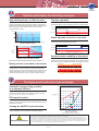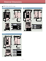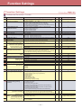
1
MEH451d Series Concepts Ideal functions to meet various needs New, compact design Simple operation Flexible through optionals A broad range of model variations Global products Actual size The FRENIC-Mini features a full range of functions, compact body, simple operation, wide model variations, and global compatibility. It will meet your needs for higher performance in machines and equipment such as conveyors, fans, pumps, centrifugal separators and food processing machines, as well as the needs for system integration, energy saving, labor saving, and total cost reduction. Quoted from “Low Power AC Drive Worldwide Outlook” (2001) published by ARC(USA) -2- Optimum performance for traversing conveyors High starting torque, at 150% or more Trip-free operation , Equipped with Fuji s original simplified torque-vector control system and the automatic torque boost function, the inverter provides consistent powerful operation (when automatic torque boost is ON, slip compensation control is ON, and when running at 5Hz or more). The remarkably improved current limiting function (stall prevention) allows trip-free operation even for an impact load. Load torque Motor speed Torque [%] Output current 0s 2.5s 5s 7.5s 10s 12.5s Time Stable operation even for a step load [Torque characteristics] Short-time operation torque 150 100 Output torque [%] 50 0 The slip compensation function permits stable operation even when the motor load fluctuates (step load). Motor speed [r/min] Load torque 100% output torque refers to the rated torque of the motor driven at 60 Hz. Motor speed Output current Continuous operation allowable range 0s 6 (5) 60 (50) Output frequency [Hz] 2.5s 5s 7.5s 10s Time Reduced motor instability at low speed 120 (100) , Fuji s unique control method improves voltage control performance and reduces motor instability at low speed to about a half or less (at 1Hz) compared with that of conventional inverters. [Output torque characteristic data] The above graph shows an example of torque characteristics obtained when FRENIC-Mini is , combined one-to-one with Fuji s standard three-phase motor (8-type series: 4 poles). Braking resistor connectable to the inverter Motor speed [r/min] FRENIC-Mini 0 Owing to a built-in braking transistor (0.4kW or larger), an optional braking resistor can be connected to increase the regenerative braking capacity for conveyance and transportation machinery that require large braking power. For inverters of 1.5kW or larger, it is possible to select the model that incorporates a braking resistor. Conventional Fuji inverter 0 [Instability characteristics] The highly used functions for fans and pumps 110 Automatic energy-saving provided as a standard function 100 90 By controlling the motor loss to a minimum, FRENIC-Mini further saves electric power when applied to fans or pumps. 80 When damper or valve is used 70 Energy saving rate varies with the motor characteristics. Required power P [%] 60 PID control function Energy saved 50 Permits motor operation while controlling temperature, pressure, or flow rate without using an external device such as temperature controller. Cooling fan ON/OFF control function 40 30 Inverter control (V/f control) 20 Inverter control (Automatic energy-saving mode) 10 , The inverter s cooling fan can be turned off while the fan or pump is stopped for noise reduction and energy savings. 0 10 20 30 40 50 60 70 80 Air or liquid flow rate Q [%] 90 100 [Energy savings effect] Energy savings rate varies with the motor characteristics. Safety Precautions 12.5s 1. The contents of this catalog are provided to help you select the product model that is best for you. Before actual use, be sure , to read the Instruction Manual/User s Manual thoroughly to assure correct operation. 2. This product is not designed and manufactured for use in machines or systems which human life is dependent upon. If you are studying use of the products in this brochure for special purposes such as for control of nuclear power stations, in sea, air or space craft, in medical or land transportation equipment, or any related systems, please contact the business office of Fuji Electric. If these products are to be used in any equipment in which there is a risk to human life or the possibility of a major loss in the event of failure, be sure to install the appropriate safety equipment. -3- The ideal functions to serve a multiplicity of needs for small-capacity inverters Compatible with a wide range of frequency settings The output frequency can be set to a maximum of 400Hz. The optimum frequency setting method can be selected to match your machine or equipment. Setting can be done by keypad panel ( keys, potentiometer), analog input (4 to 20mA, 0 to +10V, 0 to 5V, 1 to 5V), multistep speed settings (8 steps) etc. The inverter can be used for equipment that requires a high motor speed such as centrifugal separator. In this case, check the operation in combination with the motor. A transistor output is provided. This enables an overload early warning, lifetime forecast or other information signals to be output during operation. Two points can be set for a non-linear V/f pattern. One point for the non-linear V/f pattern, which can be set as desired, has been added (making a total of 2 points), and so the V/f pattern can be adjusted to match the application. Compact , Size interchangeability with Fuji s FVR-C11S series is provided. Side-by-side mounting is possible. Multiple inverter units can be mounted side-by-side inside a panel. This features helps to minimize the space used for installation. (Ambient temperature: 40˚C or less) FVR-C11S FRENIC-Mini 120 80 *Applicable models, however, are limited to single-phase and threephase 200V series with semi-standard specifications. 80 80 240 (Units: mm) (Single-phase 200V, 0.75kW or less) RS485 communications card (option) can be installed internally. , This card can be installed inside the inverter s body without changing the dimensions. RS485 communications are available as option. A model with built-in braking resistor is available on order. For inverters of 1.5kW or larger, a built-in braking resistor type can be selected. Since installation and wiring of a separate braking resistor is not required, the total mounting space is reduced. RS485 communications card (Three-phase 400V, 1.5kW) (Single-phase 200V, 0.75kW or less) -4- Simple operation and wiring Frequency setting potentiometer is standard equipment. All types of data can be displayed on the keypad. The frequency can be adjusted easily by hand. The output frequency, set frequency, load shaft speed, output current, output voltage, alarm history, input power etc. can be displayed. The control circuit terminal block cover and main circuit terminal block cover can be quickly removed. Control circuit terminal block cover A menu mode is included in the keypad. ,, The menu items include the function menu for checking or ,, ,, changing function codes, operation monitor , I/O check , ,, ,, maintenance info. and alarm info. See the FRENIC-Mini , User s Manual for details. ,, ,, ,, ,, ,, Main circuit terminal block cover Maintenance The lifetime of the DC bus capacitor can be estimated. The alarm history for the 4 latest alarms is recorded. , The capacitor s condition compared with its initial state can be confirmed. Detailed information from back as far as the 4 latest alarms can also be checked. A long-life cooling fan is included. It is possible to output lifetime forecast signal to the transistor output. Use of a long-life cooling fan (design life: 7 years with an ambient temperature: 40˚C) reduces maintenance work. Cumulative running time is recorded and displayed. This signal is output when the capacitors in the DC bus circuit, the electrolytic capacitors on the PCB or the cooling fans are nearing the end of their service life. The inverter records and displays the cumulative running time (lifetime) of the inverter itself, PCB, and cooling fan. Interface for peripheral devices and comprehensive protective functions All models are equipped with an inrush current suppression circuit. Input/output phase loss protective function It is possible to detect output phase loss at all times during starting and operation. An inrush current suppression circuit is provided as standard in all models, so the cost of peripheral devices such as input magnetic contactors can be reduced. Sink/Source can be switched. A DC reactor (DCR) connection terminal is provided as standard. A terminal for connection of a DCR, necessary for suppressing harmonics, is provided in all models. The input/output mode (Sink/Source) of the digital input terminals can be switched by means of an internal jumper switch. The motor can be protected by a PTC thermistor. In addition to the protection by an electronic thermal relay, the motor is protected by a PTC thermistor input. -5- Flexible through optionals Function code copy function Remote operation is possible. The optional remote keypad includes a built-in copy function, so function codes can be easily set. Further, function code data copying can be easily made from the original inverter to multiple inverters, using the optional copy adaptor. Remote operation can be done easily using the optional RS485 communications card, remote keypad and remote operation extension cable. Inverter support loader software is available. The inverter support loader program (Windows-based), which simplifies setting of function codes, is provided as an option. To run the program, the following optional three items are required; RS485 communications card, remote operation extension cable, and USB-RS485 converter. RS485 communications card Mounting on DIN rail Using the rail mounting base (option), the inverter can be easily mounted on a DIN rail (35mm wide). Replacement of older models with new ones is simple. The latest models can be mounted without drilling additional holes by use of the mouting adapter (option). Remote operation extension cable Remote keypad Wide variations A 400V series, in addition to the 200V series (single-phase, three-phase), is available. Models with EMC filter built-in type and with braking resistor built-in type are also available. Type1 (NEMA1) conformed model is available by attaching optional parts. Global products All standard models comply with the EC Directive (CE marking), UL standards and Canadian standards (cUL certification). All standard FRENIC-Mini inverters comply with European and North American/Canadian standards, enabling standardization of the specifications for machines and equipment used at home and abroad. If the model with built-in EMC filter is used, the model conforms to the European EMC Directive. Europe North America/Canada .. EC Directives (CE making), TUV UL standard (cUL certification) -6- Variation Caution The contents of this catalog are provided to help you select the product model that is best for you. Before actual use, be sure to read the User’s Manual thoroughly to assure correct operation. In addition to the single-phase 200V and three-phase 200V, three-phase 400V series has been newly introduced, broadening the model selection range. Model variations include EMC filter built-in type and braking resistor built-in type. Applicable motor rating Three-phase 400V series Single-phase 200V series Three-phase 200V series 0.1 FRN0.1C1E-7E FRN0.1C1E-2J 0.2 FRN0.2C1E-7E FRN0.2C1E-2J Standard specifications EMC filter built-in type 0.4 FRN0.4C1E-4E FRN0.4C1E-7E FRN0.4C1E-2J 0.75 FRN0.75C1E-4E FRN0.75C1E-7E FRN0.75C1E-2J 1.5 FRN1.5C1E-4E FRN1.5C1E-7E FRN1.5C1E-2J 2.2 FRN2.2C1E-4E FRN2.2C1E-7E FRN2.2C1E-2J 4.0 FRN4.0C1E-4E FRN3.7C1E-2J Semi-standard specifications Without EMC filter type 0.1 FRN0.1C1S-7E FRN0.1C1S-2J 0.2 FRN0.2C1S-7E FRN0.2C1S-2J 0.4 FRN0.4C1S-4E FRN0.4C1S-7E FRN0.4C1S-2J 0.75 FRN0.75C1S-4E FRN0.75C1S-7E FRN0.75C1S-2J 1.5 FRN1.5C1S-4E FRN1.5C1S-7E FRN1.5C1S-2J 2.2 FRN2.2C1S-4E FRN2.2C1S-7E FRN2.2C1S-2J 4.0 FRN4.0C1S-4E FRN3.7C1S-2J Braking resistor built-in type (Without EMC filter) 1.5 FRN1.5C1S-4E21 FRN1.5C1S-2J21 2.2 FRN2.2C1S-4E21 FRN2.2C1S-2J21 4.0 FRN4.0C1S-4E21 FRN3.7C1S-2J21 Type1 (NEMA1) conformed model is available by attaching optional parts. How to read the model number Code FRN Series name FRENIC series Code 0.1 0.2 0.4 0.75 1.5 2.2 4.0, 3.7 Applicable motor rating [kW] 0.1 0.2 0.4 0.75 1.5 2.2 4.0 Code C Application range Compact Code 1 Developed inverter series 1 FRN 1.5 C 1 E - 4 E 2 1 Code Blank,1 Built-in option None Code Blank,1 2 Brake Standard Braking resistor built-in type Code E J Version English Japanese Code 4 7 2 Input power source Three-phase 400V Single-phase 200V Three-phase 200V Code E S Enclosure EMC filter built-in type (IP20) Standard without EMC filter (IP20) Note) If “Built-in option” is “None” and “Brake” is “Standard”, the model numbers are indicated in the same format as those of the above standard specifications. -7- Standard Specifications EMC filter built-in type Three-phase series Item Specifications Input power source Three-phase 400V Type (FRNC1E-E/J) FRN0.4 C1E-4E FRN0.75 FRN1.5 C1E-4E C1E-4E FRN2.2 C1E-4E FRN4.0 C1E-4E FRN0.1 C1E-2J FRN0.2 C1E-2J FRN0.4 C1E-2J FRN0.75 FRN1.5 C1E-2J C1E-2J FRN2.2 C1E-2J FRN3.7 C1E-2J 0.4 0.75 1.5 2.2 4.0 0.1 0.2 0.4 0.75 1.5 2.2 4.0 1.1 1.9 2.8 4.1 6.8 0.30 0.57 1.1 1.9 3.0 4.2 6.5 11.0 (10.0) 17.0 (16.5) kW Rated capacity *2) kVA Input ratings Output ratings Applicable motor rating *1) Rated voltage *3) V Rated current *4) A Three-phase, 380, 400, 415V/50Hz, 380, 400, 440, 460V/60Hz 1.5 2.5 3.7 5.5 9.0 Three-phase, 200V/50Hz, 200, 220, 230V/60Hz 0.8 (0.7) Overload capability 150% of rated current for 1min, 200% of rated current for 0.5s Rated frequency 50, 60Hz 1.5 (1.4) 3.0 (2.5) 5.0 (4.2) 8.0 (7.0) Phases, voltage, frequency Three-phase, 380 to 480V, 50/60Hz Voltage/frequency variations Voltage: +10 to -15% (Voltage unbalance *10) : 2% or less) Momentary voltage dip capability *5) When the input voltage is 300V or more, the inverter continues operation. If it drops below 300V, the inverter operates for 15ms. When the input voltage is 165V or more, the inverter continues operation. If it drops below 165V, the inverter operates for 15ms. (with DCR) 0.85 1.6 3.0 4.4 7.3 0.57 0.93 1.6 3.0 5.7 8.3 14.0 (without DCR) 1.7 3.1 5.9 8.2 13.0 1.1 1.8 3.1 5.3 9.5 13.2 22.2 Required power supply capacity *7) kVA 0.6 1.1 2.0 2.9 4.9 0.2 0.3 0.6 1.1 2.0 2.9 4.9 Torque *8) % 100 50 30 50 30 Torque *9) % Rated current *6) Braking Three-phase 200V A Frequency: +5 to -5% 150 150 100 - Starting frequency: 0.0 to 60.0Hz DC injection braking Three-phase, 200 to 240V, 50/60Hz Braking time: 0.0 to 30.0s 150 Braking level: 0 to 100% of rated current IP20, UL open type *11) Enclosure (IEC 60529) Cooling method kg Weight / Mass Natural cooling Fan cooling 1.5 2.5 1.6 2.5 Natural cooling 3.0 0.7 0.7 Fan cooling 0.7 0.8 2.4 2.4 2.9 Single-phase series Item Specifications Input power source Single-phase 200V Type (FRNC1E-7E) FRN0.1 C1E-7E FRN0.2 C1E-7E FRN0.4 C1E-7E FRN0.75 C1E-7E FRN1.5 C1E-7E FRN2.2 C1E-7E kW 0.1 0.2 0.4 0.75 1.5 2.2 Rated capacity *2) kVA 0.30 0.57 1.1 1.9 3.0 4.1 5.0 (4.2) 8.0 (7.0) 11.0 (10.0) Braking Input ratings Output ratings Applicable motor rating *1) Rated voltage *3) Three-phase, 200V/50Hz, 200, 220, 230V/60Hz 0.8 A (0.7) Rated current *4) 1.5 (1.4) 3.0 (2.5) Overload capability 150% of rated current for 1min, 200% of rated current for 0.5s Rated frequency 50, 60Hz Phases, voltage, frequency Single-phase, 200 to 240V, 50/60Hz Voltage/frequency variations Voltage: +10 to -10%, Momentary voltage dip capability *5) When the input voltage is 165V or more, the inverter continues operation. If it drops below 165V, the inverter operates for 15ms. Frequency: +5 to -5% (with DCR) 1.1 2.0 3.5 6.4 11.6 17.5 (without DCR) 1.8 3.3 5.4 9.7 16.4 24.8 Required power supply capacity *7) kVA 0.3 0.4 0.7 1.3 2.4 3.5 Torque *8) % 150 100 50 30 Torque *9) % - 150 Rated current *6) A DC injection braking Starting frequency: 0.0 to 60.0Hz Braking level: 0 to 100% of rated current Natural cooling Cooling method Weight / Mass Braking time: 0.0 to 30.0s IP20, UL open type *11) Enclosure (IEC 60529) kg 0.7 Fan cooling 0.7 *1) Fuji’s 4-pole standard motor *2) Rated capacity is calculated by regarding the output rated voltage as 220V for three-phase 200V and single-phase 200V series, and as 440V for three-phase 400V series. *3) Output voltage cannot exceed the power supply voltage. *4) Use the inverter at the current given in ( ) or below when the carrier frequency setting is higher than 4kHz ( : to ) or the ambient temperature is 40˚C or higher. *5) Tested under the standard load condition (85% load for nominal applied motor). *6) Calculated under Fuji-specified conditions. 0.7 1.2 2.4 2.9 *7) Obtained when a DC REACTOR (option) is used. *8) Average braking torque obtained with AVR control OFF (Varies with the efficiency of the motor.) *9) Average braking torque obtained by use of external braking resistor (standard type available as option) Max voltage [V] - Min voltage [V] *10) Voltage unbalance [%] = x 67 (IEC 61800-3 (5.2.3)) Three-phase average voltage [V] If this value is 2 to 3%, use AC REACTOR (ACR). *11) NEMA1 kit (option) is required for the enclosure conforming to the UL standard TYPE1 (NEMA1). Use the inverter in the ambient temperature range from -10 to +40˚C. -8- Semi-standard Specifications Without EMC filter type Three-phase series Item Specifications Input power source Three-phase 400V Type (FRNC1S-E/J) FRN0.4 C1S-4E FRN0.75 FRN1.5 C1S-4E C1S-4E FRN2.2 C1S-4E FRN4.0 C1S-4E FRN0.1 C1S-2J FRN0.2 C1S-2J FRN0.4 C1S-2J FRN0.75 FRN1.5 C1S-2J C1S-2J FRN2.2 C1S-2J FRN3.7 C1S-2J 0.4 0.75 1.5 2.2 4.0 0.1 0.2 0.4 0.75 1.5 2.2 4.0 1.1 1.9 2.8 4.1 6.8 0.30 0.57 1.1 1.9 3.0 4.2 6.5 11.0 (10.0) 17.0 (16.5) kW Rated capacity *2) kVA Input ratings Output ratings Applicable motor rating *1) Rated voltage *3) V Rated current *4) A Three-phase, 380, 400, 415V/50Hz, 380, 400, 440, 460V/60Hz 1.5 2.5 3.7 5.5 9.0 Three-phase, 200V/50Hz, 200, 220, 230V/60Hz 0.8 (0.7) Overload capability 150% of rated current for 1min, 200% of rated current for 0.5s Rated frequency 50, 60Hz 1.5 (1.4) 3.0 (2.5) 5.0 (4.2) 8.0 (7.0) Phases, voltage, frequency Three-phase, 380 to 480V, 50/60Hz Voltage/frequency variations Voltage: +10 to -15% (Voltage unbalance *10) : 2% or less) Momentary voltage dip capability *5) When the input voltage is 300V or more, the inverter continues operation. If it drops below 300V, the inverter operates for 15ms. When the input voltage is 165V or more, the inverter continues operation. If it drops below 165V, the inverter operates for 15ms. (with DCR) 0.85 1.6 3.0 4.4 7.3 0.57 0.93 1.6 3.0 5.7 8.3 14.0 (without DCR) 1.7 3.1 5.9 8.2 13.0 1.1 1.8 3.1 5.3 9.5 13.2 22.2 Required power supply capacity *7) kVA 0.6 1.1 2.0 2.9 4.9 0.2 0.3 0.6 1.1 2.0 2.9 4.9 Torque *8) % 100 50 30 50 30 Torque *9) % Rated current *6) Braking Three-phase 200V A Frequency: +5 to -5% 150 150 100 - Starting frequency: 0.0 to 60.0Hz DC injection braking Three-phase, 200 to 240V, 50/60Hz Braking time: 0.0 to 30.0s 150 Braking level: 0 to 100% of rated current IP20, UL open type *11) Enclosure (IEC 60529) Cooling method kg Weight / Mass Natural cooling Fan cooling 1.1 1.7 1.2 1.7 Natural cooling 2.3 0.6 0.6 Fan cooling 0.6 0.7 1.7 1.7 2.3 Single-phase series Item Specifications Input power source Single-phase 200V Type (FRNC1S-7E) FRN0.1 C1S-7E FRN0.2 C1S-7E FRN0.4 C1S-7E FRN0.75 C1S-7E FRN1.5 C1S-7E FRN2.2 C1S-7E kW 0.1 0.2 0.4 0.75 1.5 2.2 Rated capacity *2) kVA 0.30 0.57 1.1 1.9 3.0 4.1 5.0 (4.2) 8.0 (7.0) 11.0 (10.0) Input ratings Output ratings Applicable motor rating *1) Rated voltage *3) V Rated current *4) A 0.8 (0.7) 1.5 (1.4) 3.0 (2.5) Overload capability 150% of rated current for 1 min, 200% of rated current for 0.5s Rated frequency 50, 60Hz Phases, voltage, frequency Single-phase, 200 to 240V, 50/60Hz Voltage/frequency variations Voltage: +10 to -10% Momentary voltage dip capability *5) When the input voltage is 165V or more, the inverter continues operation. If it drops below 165V, the inverter operates for 15ms. Frequency: +5 to -5% (with DCR) 1.1 2.0 3.5 6.4 11.6 17.5 (without DCR) 1.8 3.3 5.4 9.7 16.4 24.8 kVA 0.3 0.4 0.7 1.3 2.4 3.5 Torque *8) % 150 100 50 30 Torque *9) % - 150 Rated current *6) A Required power supply capacity *7) Braking Three-phase, 200V/50Hz, 200, 220, 230V/60Hz Starting frequency: 0.0 to 60.0Hz DC injection braking Enclosure (IEC 60529) Cooling method Weight / Mass Braking time: 0.0 to 30.0s Braking level: 0 to 100% of rated current IP20, UL open type *11) Natural cooling kg 0.6 Fan cooling 0.6 0.6 *1) Fuji’s 4-pole standard motor *2) Rated capacity is calculated by regarding the output rated voltage as 220V for three-phase 200V and single-phase 200V series, and as 440V for three-phase 400V series. *3) Output voltage cannot exceed the power supply voltage. *4) Use the inverter at the current given in ( ) or below when the carrier frequency setting is higher than 4kHz ( : to ) or the ambient temperature is 40˚C or higher. *5) Tested under the standard load condition (85% load for nominal applied motor). *6) Calculated under Fuji-specified conditions. 0.8 1.7 2.3 *7) Obtained when a DC REACTOR (option) is used. *8) Average braking torque obtained with AVR control OFF (Varies with the efficiency of the motor.) *9) Average braking torque obtained by use of external braking resistor (standard type available as option) Max voltage [V] - Min voltage [V] *10) Voltage unbalance [%] = x 67 (IEC 61800-3 (5.2.3)) Three-phase average voltage [V] If this value is 2 to 3%, use AC REACTOR (ACR). *11) NEMA1 kit (option) is required for the enclosure conforming to the UL standard TYPE1 (NEMA1). Use the inverter in the ambient temperature range from -10 to +40˚C. -9- Semi-standard Specifications Braking resistor built-in type (Without EMC filter) Item Specifications Input power source Three-phase 400V Type (FRNC1S-E/J21) FRN1.5 C1S-4E21 FRN2.2 C1S-4E21 FRN4.0 C1S-4E21 FRN1.5 C1S-2J21 FRN2.2 C1S-2J21 FRN3.7 C1S-2J21 1.5 2.2 4.0 1.5 2.2 4.0 2.8 4.1 6.8 3.0 4.1 6.4 kW Rated capacity *2) kVA Input ratings Output ratings Applicable motor rating *1) Rated voltage *3) V Rated current *4) A Three-phase, 380, 400, 415V/50Hz, 380, 400, 440, 460V/60Hz 3.7 5.5 9.0 Overload capability 150% of rated current for 1min, 200% of rated current for 0.5s Rated frequency 50, 60Hz Three-phase, 200V/50Hz, 200, 220, 230V/60Hz 8.0 (7.0) 11.0 (10.0) 17.0 (16.5) Phases, voltage, frequency Three-phase, 380 to 480V, 50/60Hz Three-phase, 200 to 240V, 50/60Hz Voltage/frequency variations Voltage: +10 to -15% (Voltage unbalance *10) : 2% or less) Frequency: +5 to -5% Momentary voltage dip capability *5) When the input voltage is 300V or more, the inverter continues operation. If it drops below 300V, the inverter operates for 15ms. When the input voltage is 165V or more, the inverter continues operation. If it drops below 165V, the inverter operates for 15ms. (with DCR) 3.0 4.4 7.3 5.7 8.3 (without DCR) 5.9 8.2 13.0 9.5 13.2 22.2 Required power supply capacity *7) kVA 2.0 2.9 4.9 2.0 2.9 4.9 % 150 100 100 150 100 100 s 18 12 8 18 12 8 % 3 2 1.5 3 2 1.5 Rated current *6) A Torque *8) Braking Three-phase 200V Braking time Duty cycle DC injection braking Starting frequency: 0.0 to 60.0Hz Enclosure (IEC 60529) Braking level: 0 to 100% of rated current IP20, UL open type *11) Cooling method Weight / Mass Braking time: 0.0 to 30.0s 14.0 Fan cooling kg 1.8 1.8 *1) Fuji’s 4-pole standard motor *2) Rated capacity is calculated by regarding the output rated voltage as 220V for three-phase 200V series, and as 440V for three-phase 400V series. *3) Output voltage cannot exceed the power supply voltage. *4) Use the inverter at the current given in ( ) or below when the carrier frequency setting is higher than 4kHz ( : to ) or the ambient temperature is 40˚C or higher. *5) Tested under the standard load condition (85% load for nominal applied motor). *6) Calculated under Fuji-specified conditions. 2.5 1.8 1.8 2.5 *7) Obtained when a DC REACTOR (option) is used. *8) Average braking torque obtained with AVR control OFF (Varies with the efficiency of the motor.) *9) Average braking torque obtained by use of external braking resistor (standard type available as option) Max voltage [V] - Min voltage [V] *10) Voltage unbalance [%] = x 67 (IEC 61800-3 (5.2.3)) Three-phase average voltage [V] If this value is 2 to 3%, use AC REACTOR (ACR). *11) NEMA1 kit (option) is required for the enclosure conforming to the UL standard TYPE1 (NEMA1). Use the inverter in the ambient temperature range from -10 to +40˚C. - 10 - Common Specifications Common specifications Setting range Output frequency Item Related function code For operation at 120Hz or more, test the inverter F03 in advance by combining it with the motor. Explanation Maximum frequency 25 to 400Hz Base frequency 25 to 400Hz Starting frequency 0.1 to 60.0Hz Carrier frequency 0.75 to 15kHz Remarks For operation at 120Hz or more, test the inverter F04 in advance by combining it with the motor. F23 Frequency may drop automatically to protect the inverter running at 7kHz or more. This protective operation can be canceled by function code H98. Accuracy(Stability) Analog setting: –0.2% of maixmum frequency (at 25–10˚C) Digital setting: –0.01% of maixmum frequency (at -10 to +50˚C) Setting resolution Analog setting: 1/1000 of maixmum frequency (ex. 0.06Hz at 60Hz, 0.4Hz at 400Hz) Keypad setting: 0.01Hz (99.99Hz or less), 0.1Hz (100.0Hz or more) Link setting: Selectable from 2 types • 1/2000 of maixmum frequency (ex. 0.003Hz at 60Hz, 0.02Hz at 400Hz) • 0.01Hz (fixed) Control method V/f control (Simplified torque-vector control) Voltage/freq. characteristic • Possible to set output voltage at base frequency and at maixmum output frequency (common spec). • AVR control can be turned ON or OFF (Factory setting: OFF). H98 Includes the potentiometer on the keypad. , Setting with keys. Three-phase 200V, single-phase 200V: 80 to 240V F03 to F05 Three-phase 400V: 160 to 500V (Non-linear V/f setting) 1 point (Desired voltage and frequency can be set.) H50,H51 Torque boost can be set with the function code F09. Torque boost F26,F27 Set when 0, 1, 3, or 4 is selected at F37. (Load selection) Select application load type with the function code F37. 0: Variable torque load 1: Constant torque load 2: Auto torque boost 3: Auto energy-save operation (variable torque load in acceleration/deceleration) 4: Auto energy-save operation (constant torque load in acceleration/deceleration) 5: Auto energy-save operation (auto torque boost in acceleration/deceleration) F09,F37 F09,F37 150% or over (Auto torque boost in 5Hz operation) Starting torque Start/stop Remote keypad (option) is also usable. F02 Link operation: Communication via RS485 RS485 communication function is optional. H30,y01 to y10 y99 Can be set with built-in potentiometer (standard) Remote keypad (option) is also usable. F01, C30 Keypad operation: Start (FWD/REV) and stop with , keys External signals (5 digital inputs): FWD, REV, coast to stop command, etc. Frequency setting Can be set with or key Can be set with external potentiometer (1 to 5kΩ) Analog input • Connected to analog input terminals 13, 12, 11. F01, C30 • Potentiometer must be provided. • Can be set with external voltage/current output • 0 to +10V DC (0 to +5V DC)/0 to 100% (terminal 12) • +4 to +20mA DC/0 to 100% (terminal C1) F18,C32 to C34 F18,C37 to C39 E01 to E03 E98,E99 Control (Inverse operation) • Can be reversed with digital input signal (IVS) • +10 to 0V DC (+5 to 0V DC)/0 to 100% (terminal 12) • +20 to +4mA DC/0 to 100% (terminal C1) Multistep frequency: Selectable from 8 steps (step 0 to 7 ) Link operation: Can be set with communication via RS485 Running status signal C05 to C11 RS485 communication function is optional. Transistor output (1 point) : RUN, FAR, FDT, LU, etc. H30,y01 to y10 E20 Relay output (1 point) : Alarm relay output or multipurpose relay output signal Acceleration/ deceleration time Analog output (1 point) : Output frequency, output current, output voltage, input power, etc. F30,F31 0.00 to 3600s *If 0.00s is set, the time setting is cancelled and acceleration and deceleration is made according to the pattern given with an external signal. F07,F08 Acceleration and deceleration time can be independently set and selected with digital input signal (1 point). E10,E11 (Pattern) Acceleration and deceleration pattern can be selected from 4 types: Linear, S-curve (weak), S-curve (strong), Non-linear H07 Frequency limiter High and Low limiters can be set. F15 F16 Bias frequency Bias of set frequency and PID command can be independently set. F18 C50 to C52 Gain for frequency setting Proportional relation between analog input signal and output frequency can be set. Ex. When voltage input signal is between 0 and +5V DC, the inverter can be used at +5V DC/max output frequency by setting gain to 200%. Jump frequency control 3 operation points and their common jump hysteresis width (0 to 30Hz) can be set. C01 to C04 Jogging operation • Can be operated using digital input signal or keypad. • Acceleration and deceleration time (same duration used only for jogging) can be set. • Jogging frequency: 0.00 to 400.0Hz H54 C20 Voltage signal (terminal 12) and current signal (terminal C1) can be set independently. C32 to C39 Timer operation Operation starts and stops at the time set from keypad (1 cycle). C21 Auto-restart after momentary power failure Restarts the inverter without stopping the motor after instantaneous power failure. F14 Slip compensation Compensates for decrease in speed according to the load, enabling stable operation. P09 Current limit Keeps the current under the preset value during operation. F43,F44 - 11 - Common Specifications Common specifications Item Explanation PID control Remarks PID control is possible using analog input signals. Inverse operation can be set using digital input signal (IVS) or the function code J01. Select the control mode with J01. Process commands Select the kind of remote process command with J02, E60 to E62. , key operation: Set frequency[Hz]/Max frequency[Hz] x100[%] Control Built-in potentiometer • Voltage input (terminal 12) : 0 to +10V DC/0 to 100% • Current input (terminal C1) : +4 to +20mA DC/0 to 100% • RS485 communication : Set frequency[Hz]/Max frequency[Hz] x100[%] Automatic deceleration E60 E61 E62 J02 Feedback signal • Voltage input (terminal 12) : 0 to 10V DC/0 to 100% • Current input (terminal C1) : +4 to +20mA DC/0 to 100% Feedback signal can be selested with E61, E62. Makes the deceleration time 3 times longer to avoid trip when DC link circuit voltage exceeds the overvoltage limit. (Set at the function code H69 : 1.) • Trip may occur even when deceleration time is prolonged if the moment of inertia is large. • This function does not come ON during constant speed operation. E61 E62 H69 H70 • Minimizes motor losses at light load. • Can be set in accordance with the kind of load (variable torque load, constant torque load, auto torque boost). F37 Fan stop operation Detects inverter internal temperature and stops cooling fan when the temperature is low. Running • Speed monitor, output current [A], output voltage [V], input power [kW], PID reference, PID feedback value Select the speed monitor to be displayed from the following: • Output frequency (before slip compensation) [Hz], output frequency (after slip compensation) [Hz], set frequency [Hz], Load shaft speed [r/min], line speed [m/min], constant rate of feeding time[min]. Speed monitor can display the speed set at E48. E43 E48 Stopping Displays the same contents as displayed during running. Same as above Trip mode Displays the cause of trip by codes as follows. : Overcurrent during acceleration : Overcurrent at constant speed : Undervoltage : Overvoltage during acceleration : Overvoltage during constant speed : External thermal relay tripped : Overheating of the DB circuit : Inverter unit overload : KEYPAD communication error : Operation procedure error : Data save error due to undervoltage For details, refer to the protective functions (p.22). Indication Prevents tripping before the inverter becomes overloaded. Energy saving operation H06 Same as above : Overcurrent during deceleration : Input phase loss : Output phase loss : Overvoltage during deceleration : Overheating of the heat sink : Motor protection (PTC thermistor) : Motor overload : Memory error : CPU error : RS485 error Trip history: Saves and displays the last 4 trip codes and their detailed description. (Even with the main power off, trip history data of the last 4 trips are retained.) For details, refer to the instruction manual or FRENIC-Mini User’s Manual. Protects and stops the inverter when the following overcurrent flows during acceleration, deceleration, or constant speed rotation: • Overcurrent caused by overload (Short-circuit) • Overcurrent caused by short-circuit in output circuit Ground fault can be detected at starting. (Ground fault) • Overcurrent caused by ground fault Overcurrent Protection J02 Overload prevention control Running or trip mode Overvoltage Stops the inverter by detecting overvoltage in DC link circuit during braking. Incoming surge Protects the inverter from surge voltage entering between main circuit power cable and earth cable. Undervoltage Stops the inverter by detecting voltage drop in DC link circuit. Input phase loss Detects input phase loss to shut down the inverter. This function prevents the inverter from undergoing heavy stress that Non-operation is also selectable. may be caused by input phase loss or interphase unbalance voltage exceeding 6%, which may damage the inverter. If the connected load is light or a DC reactor is connected to the inverter, this function will not detect input phase loss if any. H98 Detects breaks in inverter output wiring at the start of running and during running, stopping the inverter output. Non-operation is also selectable. H98 Output phase loss 200V series: 400V DC 400V series: 800V DC F14 200V series: 200V DC 400V series: 400V DC Details of operation can be selected with the function code F14. (Heat sink) Stops the inverter by detecting inverter heat sink temperature. Overheating (Braking resistor) Stops the inverter and built-in braking transistor if "discharging capability" or "average allowable loss" set for the braking resistor is exceeded more frequently than the set number of times. Motor protection F50,F51 Stops the inverter by detecting the output current and internal temp. To calculate the IGBT internal temp. Overload (Electronic thermal) Stops the inverter to protect the motor when the set output. Current is exceeded. Thermal time constant can be adjusted (0.5 to 75.0min). F10 to F12 (PTC thermistor) A PTC thermistor input stops the inverter to protect the motor. H26,H27 (Overload early warning) Warning signal can be output based on the set level before the inverter trips. Related transistor output: OL When the motor is tripped and stopped, this function automatically resets the tripping state and restarts operation. Activated when the motor is tripped with the following trip codes: Installation location Shall be free from corrosive gases, flammable gases, oil mist, dusts, and direct sunlight. Indoor use only. Pollution degree 2 when the Low Voltage Directives are used. Ambient temperature -10 to +50˚C -10 to 40˚C when inverters are installed side by side without clearance. Ambient humidity 5 to 95%RH (no condensation) Altitude Altitude [m] 1,000 or lower 1,001 to 2,000 2,001 to 3,000 , , , Amb. temp. , , , , , * If the altitude exceeds 2000m, insulate the interface circuit from the main power supply to conform to the Low Voltage Directives. Output derating None None Decreases* 3mm (vibration width): 2 to less than 9Hz, 2m/s2: 20 to less than 55Hz Vibration Storage , 9.8m/s2: 9 to less than 20Hz 1m/s2: 55 to less than 200Hz -25 to +70˚C Amb. humidity 5 to 95%RH (no condensation) - 12 - E34,E35 Waiting time before resetting and the number of H04,H05 retry times can be set. Retry function , Environment Related function code J01 Protective Functions Protective Functions Function Alarm output Related LED monitor (30A,B,C) Note) function code Description Overcurrent • Stops the inverter output to protect the inverter from an overcurrent resulting from overload. During acceleration Protection • Stops the inverter output to protect the inverter from an overcurrent due to a short-circuit in the output circuit. During deceleration While running at constant speed • Stops the inverter output to protect the inverter from an overcurrent due to a ground fault in the output circuit. This protection is effective only when the inverter starts. If you turn on the inverter without removing the ground fault, this protection may not work. Overvoltage The inverter stops when it detects an overvoltage (400V DC in a 200V series, During acceleration protection 800V DC in a 400V series) in the DC link circuit. During deceleration While running at constant speed(Stopped) Protection is not assured if excess AC line voltage is applied inadvertently. Undervoltage Stops the inverter when the DC link circuit voltage drops below the undervoltage level (200V DC in a 200V series, 400V DC in a 400V series). protection However, if "4 or 5" is selected for F14, no alarm is output even if there is a drop in the DC link circuit voltage. Input phase loss Detects input phase loss, stopping the inverter output. This function prevents the inverter from undergoing heavy stress protection that may be caused by input phase loss or interphase voltage unbalance and may damage the inverter. F14 H98 If connected load is light or a DC reactor is connected to the inverter, this funtion will not detect input phase loss if any. In single-phase series of inverters, this function is disabled by factory default. H98 H43 F50,F51 Overheat protection Output phase loss protection Detects breaks in inverter output wiring at the start of running and during running, stopping the inverter output. • Stops the inverter when it detects excess heat sink temperature in case of cooling fan failure or overload. Inverter Braking resistor • When the built-in or external braking resistor overheats, the inverter stops running. * It is necessary to set the function code corresponding to the braking resistor used (built-in or external). Overload protection Calculates the IGBT internal temperature from the output current and internal temperature detection, stopping the inverter. F10 Electronic thermal The inverter stops running the motor to protect the motor in accordance with the electronic thermal Motor protection overload relay function setting. • Protection of a standard motor over the entire frequency range. • Protects the inverter motor over the entire frequency range. PTC thermistor * The operation level and thermal time constant can be set. F11,F12 • A PTC thermistor input stops the inverter to protect the motor. H26,H27 A PTC thermistor is connected between terminals C1 and 11, and a 1kΩ external resistor is Overload early connected between terminals 13 and C1. Outputs a preliminary alarm at a preset level before the inverter is stopped by the electronic thermal warning function for the purpose of protecting the motor. Stall prevention Operates when the instantaneous overcurrent hits the set limit. - - E34,E35 - - H12 Instantaneous overcurrent limit: Operates if the inverter output current exceeds the instantaneous overcurrent External alarm input limit to prevent the inverter from tripping (during acceleration or negative constant speed operation). • Stops the inverter with an alarm through the digital input signal (THR). Alarm relay output • The inverter outputs a relay contact signal when the inverter issues an alarm and stopped. (for any fault) <Alarm reset> E01 to E03 E98, E99 E20,E27 - E01 to E03 The alarm stop state is reset by pressing the E98,E99 key or by the digital input signal (RST). <Saving the alarm history and detailed data> The information on the previous 4 alarms can be saved and displayed. Memory error The inverter checks memory data after power-on and when the data is written. If a memory error is detected, the inverter stops. Remote keypad F02 The inverter stops by detecting a communication error between the inverter and the remote keypad communication error (option) during operation from the remote keypad. CPU error If the inverter detects a CPU error caused by noise or some other factor, the inverter stops. Operation error STOP key Pressing priority if the inverter is running by any run commands given via the terminals or communications H96 key on the keypad forces the inverter to decelerate and stop the motor even (link operation). After the motor stops, the inverter issues alarm " Start check Inverters prohibit any run operations and displays " function any run command is given when: ." " on the LED of keypad if • Powering up • Releasing an alarm ( key turned on) • Link command (LE) has switched inverter operations RS485 communication error On detecting an RS485 communication error, the inverter displays the error code. Data save error If the data could not be saved during activation of the undervoltage protection function, the inverter during undervoltage displays the error code. Overload In the event of overheating of the heat sink or overload (alarm display: prevention control the output frequency of the inverter is reduced to prevent the inverter from tripping. Note) A or ), - in the alarm output (30A,B,C) column indicates that there are cases where an alarm is not output in accordance with the function code. - 13 - - External Dimensions EMC filter built-in type Fig. 1 6.5 6 Fig. 2 80 67 D 6.5 2 D1 6.5 7 D2 D 6.5 2 D1 D2 4-5x7(Long hole) 6 5 170 180 120 110 130 118 5 5 6 5 4-5x6(Long hole) 110 97 Rating plate 60 10 10.5 D3 Power supply voltage Power supply voltage D3 10 21.2 10 21.2 25 36.2 50 61.2 Unit (mm) 182 6 2 118 64 6 245 180 168 6 2- 5 10.5 Rating plate 5 92 27 85.5 Power supply voltage Three-phase 400V Single-phase 200V 6 Three-phase 200V Type Dimensions (mm) W D D1 D2 D3 Three- FRN0.4C1E-4E 158 40 61.5 phase 89 118 182 64 85.5 400V FRN0.75C1E-4E Singlephase FRN0.75C1E-7E 60 139 99 40 55.2 200V 25 36.2 3 1.5 D2 Fig. 3 6 D3 W Dimensions (mm) Type D D1 Single- FRN0.1C1E-7E 100 phase FRN0.2C1E-7E 90 200V FRN0.4C1E-7E 115 FRN0.1C1E-2J Three- FRN0.2C1E-2J 100 90 phase 115 200V FRN0.4C1E-2J FRN0.75C1E-2J 140 140 128 Rating plate Type FRN1.5C1E-4E FRN2.2C1E-4E FRN4.0C1E-4E FRN1.5C1E-7E FRN2.2C1E-7E FRN1.5C1E-2J FRN2.2C1E-2J FRN3.7C1E-2J - 14 - Without EMC filter type Fig. 1 Fig. 2 80 67 6.5 6 110 97 D 6.5 2 D1 6.5 7 D2 2 D1 D2 4-5x7(Long hole) 6 5 120 110 130 118 5 5 6 5 4-5x6(Long hole) D 6.5 Rating plate Dimensions (mm) D D1 D2 Type 1.5 FRN0.1C1S-7E Single-phase FRN0.2C1S-7E FRN0.4C1S-7E 200V FRN0.75C1S-7E FRN0.1C1S-2J** Three-phase FRN0.2C1S-2J** FRN0.4C1S-2J** 200V FRN0.75C1S-2J** 80 70 95 140 90 25 50 80 10 95 120 70 Dimensions (mm) D D1 D2 40 Three-phase FRN0.4C1S-4E** 115 75 400V FRN0.75C1S-4E** 139 64 Power supply voltage 10 Type 3 Power supply voltage Rating plate 25 50 Fig. 3 Fig. 4 Unit (mm) 110 97 D 6.5 2 D1 D2 140 128 6 2 75 64 2- 5 6 4-5x7(Long hole) 139 6 6 180 168 Power supply Type voltage Three-phase FRN1.5C1S-4E** 400V FRN2.2C1S-4E** Single-phase FRN1.5C1S-7E 200V Three-phase FRN1.5C1S-2J** FRN2.2C1S-2J** 200V 6 Rating plate 5 Dimensions (mm) D D1 D2 139 75 149 85 64 6 6 130 118 6 5 6.5 7 139 75 Note) • The symbols ** followed by the inverter type FRNC1S-2E/J represent the following numeral codes: 21 (Braking resistor built-in type), None (Standard) - 15 - 5 Rating plate Power supply voltage Three-phase 400V Single-phase 200V Three-phase 200V Type FRN4.0C1S-4E** FRN2.2C1S-7E FRN3.7C1S-2J** Keypad Operations Keypad switches and functions LED monitor Run key When the motor is running or stopped: The monitor displays the speed monitor (such as output frequency before slip compensation, after slip compensation, set frequency, motor speed, load shaft speed), output voltage, output current, output voltage, and input power. Alarm mode: The monitor shows the cause of trip with a fault code. Used to start the operation. While the motor is stopped: This key is invalid if the function code (operation by external signals). is set to Program/Reset key Used to change the mode. Programming mode: Used to shift the digit (cursor movement) to set function codes or data. Potentiometer Used to set the frequency, or make auxiliary frequency setting 1, 2, and issue the PID process commands. Alarm mode: Resets a trip. Function/Data select key Used to change the LED monitor and to store the function codes and data. Stop key Used to stop the operation. During operation: This key is invalid if the function code (operation by external signals). The inverter stops when the function code to or . Up/Down keys During operation: Used to increase or decrease the frequency or motor speed. In data setting: Used to increase or decrease the function code number or data set value. is set to is set Monitor display and key operation The keypad modes are classified in the following 3 modes. Programming mode STOP RUN Operation mode Monitor, keys Running mode STOP RUN Displays the output frequency, set frequency, loaded motor speed, input power, output current, output voltage, and motor speed. Monitor Displays the function code or data code. Displays the trip content or alarm history. Function <Unit indication> Frequency and speed: None Output current: Output voltage: Input power: Display ON Blinking Switches to stop mode. Switches to running mode. Function Digit shift (cursor movement) in function code/data setting Switches to programming Switches to programming Releases the trip and mode (STOP). mode (RUN). switches to stop mode. Function Keys Alarm mode Changes the display between function code and data code, stores data code, and updates then function code. Increases/decreases the function code number Function and data code. Function Function Invalid Invalid Switches to programming mode (STOP). ON Switches the LED monitor display. Blinking/ON Displays the operation information. Increases/decreases the frequency, motor speed, and line speed to be set. Displays the alarm history. Switches to running mode (RUN). Invalid Invalid Invalid Switches to running mode (STOP). Invalid This keypad supports a full menu mode which allows you to set or display the following information. Changed function code, operation monitor, I/O check, maintenance information, and trip information For details, refer to the FRENIC-Mini Instruction Manual or User’s Manual. - 16 - Terminal Functions Terminal Functions Main circuit Symbol Functions Related function code Remarks L1/R, L2/S, L3/T Power input Connect a three-phase power supply. Three-phase 200V, 400V series L1/L, , L2/N Connect a single-phase power supply. ( indicates the empty terminal.) Single-phase 200V, 100V series U, V, W Inverter output Connect a three-phase induction motor. P(+), P1 For DC REACTOR Connect the DC REACTOR. P(+), N(-) For DC bus connection Used for DC bus connection system. P(+), DB For EXTERNAL BRAKING RESISTOR Used for connection of the optional external BRAKING RESISTOR. Wiring is required for the braking resistor built-in type. Grounding Two terminals are provided. G Analog input Terminal name Ground terminal for inverter chassis 13 Potentiometer power supply +10V DC power supply for frequency setting potentiometer (1 to 5kΩ) 12 Voltage input 0 to +10V DC / 0 to 100% 0 to +5V DC / 0 to 100% or +1 to +5V DC / 0 to 100% can be selected by function setting. (Inverse operation) +10 to +0V DC / 0 to 100% (switchable by digital input signal) Allowable maximum output current: 10mA Input impedance: 22kΩ F18, Allowable maximum input voltage: 15V DC C32 to C34 If input voltage is +10V DC or over, the inverter assumes it to be +10V DC. (PID control) Used for reference signal (PID process command) or PID feedback signal. E61 E61 (Frequency aux. setting) Used as additional auxiliary setting to various main settings of frequency. +4 to +20mA DC / 0 to 100% Current input (Inverse operation) +20 to +4mA DC / 0 to 100% (switchable by digital input signal) C1 Input impedance: 250Ω F18, Allowable maximum input current: +30mA DC C35 to C37 If input voltage is +20mA DC or over, the inverter assumes it to be +20mA DC. E62 (PID control) Used for reference signal (PID process command) or PID feedback signal. (For PTC thermistor) Connects PTC thermistor for motor protection. Connect external resistor 1kΩ to terminal 13 - C1. H26, H27 E62 (Frequency aux. setting) Used as additional auxiliary setting to various main settings of frequency. 11 Common Common for analog input/output signals (12, 13, C1) Isolated from terminal CM and Y1E. X1 Digital input 1 X2 Digital input 2 X3 Digital input 3 FWD Forward operation command Reverse operation command The following functions can be set at terminals X1 to X3, FWD, and REV for signal input. (FWD and REV functions are factory-set at FWD and REV terminals, respectively. <Common function> Source/Sink changeover function: Source and sink are changeable using the built-in jumper switch. Contact activation mode changeover function: ON timing can be changed between short-circuit of terminals X1 and CM and open circuit of them. The same setting is possible between CM and any of the terminals among X2, X3, FWD, and REV. <ON state> E01 to E03 • Source current: 2.5 to 5mA (When input voltage is 0V) • Maximum input voltage: 2V <OFF state> • Allowable maximum leakage current: 0.5mA E98, E99 • Maximum terminal voltage: 22 to 27V REV When FWD and REV are simultaneously ON, the motor decelerates and stops. This function can (REV) Reverse operation command (REV): ON… The motor runs in the reverse direction. OFF…The motor decelerates and stops. be set only for the terminals FWD and REV. (FWD) Forward operation command Digital input (SS1) Multistep freq. (SS2) selection (SS4) (RT1) ACC/DEC time selection (FWD): ON… The motor runs in the forward direction. (FWD): OFF…The motor decelerates and stops. 2 (0, 1) different frequencies are selectable. 4 (0 to 3) different frequencies are selectable. 8 (0 to 7) different frequencies are selectable. Frequency 0 indicates the frequency set by the keypad, built-in potentiometer or analog signal. (RT1): ON… ACC/DEC time 2 is effective. (RT1): OFF…ACC/DEC time 1 is effective. C05 to C11 Frequency Digital input 0 1 2 3 4 5 6 7 (SS1) - ON - ON - ON - ON (SS2) - - ON ON - - ON ON (SS4) - - - - ON ON ON ON Switchable during ACC/DEC operation E10, E11 (HLD) 3-wire operation stop Used for 3-wire operation. (HLD): ON… The inverter self-holds FWD or REV signal. command (HLD): OFF… The inverter releases self-holding. (BX) Coast-to-stop command (BX): ON…The inverter output is shut off immediately and the motor will coast-to-stop. No alarm signal will be output. (RST) Alarm reset (RST): ON… Faults are reset. ON signal should be held for more than 0.1s. (THR) Trip command (External fault) (THR): OFF…The inverter output is shut off and the motor coasts-to-stop. Alarm signal (JOG) Jogging operation will be output. (JOG): ON… JOG frequency is effective. (FWD):ON or (REV): ON…The inverter operates with JOG frequency. C20, H54 (Hz2/Hz1) Freq. set 2/ Freq. set 1 (Hz2):ON or (Hz1): ON…Freq. set 2 is effective. F01, C30 (WE-KP) Write enable for KEYPAD (WE-KP): ON… The function code data can be changed from the keypad. Data can be changed when this function is not allocated. (Hz/PID) PID control cancel (Hz/PID): ON…The PID control is canceled, and frequency set by multistep frequency, keypad or analog input. J01 to J06 F01, C30 (IVS) Inverse mode changeover (IVS): ON…Operation mode (normal operation/ inverse operation) can be changed. (LE) Link enable (RS485, Bus) (LE): ON…The link operation is effective. (RS485 or Bus (Option)) H30, y99 (PID-RST) PID integral/differential reset (PID-RST): ON…PID integration and differentiation are reset. (PID-HLD) PID integral hold (PID-HLD): ON…PID integration is temporarily stopped. PLC PLC terminal Connect to PLC output signal power supply. Common for 24V power (terminal P24). +24V 50mA max. CM Common Common for digital input signal. Isolated from terminal 11 and Y1E. - 17 - Terminal Functions Terminal Functions Analog output Symbol Terminal name Functions Related function code Remarks FMA Analog monitor Voltage output: 0 to 10V F30,F31 • Output frequency (Before slip compensation) • Output current Max. current: 2mA • Output frequency (After slip compensation) • Output voltage • Input power • PID feedback value • DC link circuit voltage • Analog output test (+) Up to two analog voltmeters can be connected. 11 Common Common for analog input/output signals (FMA). Y1 Insulated from the terminals CM and Y1E. 27V max., 50mA max. E20 The following functions can be set at terminal Y1, signal output. • Contact activation mode changeover function: ON timing can be changed OFF state maximum leakage current: 0.1mA ON state maximum output voltage: 2V at 50mA by shorting terminals Y1 and Y1E and opening them. (RUN) Inverter running (speed exists) Comes ON when the output frequency is higher than starting frequency. Transistor output (RUN2) Inverter output on (FAR) Speed/freq. arrival Comes on when the output frequency is higher than the starting frequency or DC injection brake is applied. Comes ON when the motor speed reaches the set frequency. (Condition: Operation command is ON.) FAR hysteresis width (fixed): 2.5Hz Hysteresis width (fixed): 1.0Hz (FDT) Speed/freq. detection Comes ON when the output frequency is above the detectable level and goes OFF when below the detectable level. E31 Transistor output (LV) Undervoltage detection Comes ON when the inverter stops because of undervoltage while the operation command is ON. (IOL) Inverter output limit (limit on current) Comes ON when the inverter is limiting the current. F43,F44 (IPF) Auto-restarting F14 Comes ON during auto restart operation (after momentary power failure and until completion of restart) (OL) Overload early warning (motor) Comes ON when the electronic thermal relay value is higher than the preset alarm level. F10 to F12 (TRY) Auto-resetting mode Comes ON during auto reset mode. H04,H05 (LIFE) Lifetime alarm Outputs alarm signal according to the preset lifetime level. H42,H43,H98 H70 (OLP) Overload preventive control Comes ON during inverter control for avoiding overload. (ID) Current detection Comes ON when a current larger than the set value has been detected for the timer-set time. E34,E35 (IDL) Small current detection Comes ON when a current smaller than the set value has been detected for the timer-set time. E34,E35 LINK Relay output (ALM) Alarm relay (for any fault) Alarm signal is output as the transistor output signal. Y1E Transistor output common Emitter output of transistor output signal (Y1) Isolated from terminal 11 and CM. 30A,30B, 30C Alarm relay output (for any fault) Contact rating : 250V AC, 0.3A, cosφ=0.3 48V DC, 0.5A, non-inductive E27 RJ45 connector is used. For the transmission specifications, refer to page 25. H30 y01 to y10, y99 RS485 port RS485 I/O terminal connector *1 • Outputs a contact signal (SPDT) when a protective function is activated to stop inverter. • This terminal can be used as the multi-purpose relay output signal. (Possible to select a terminal similar to Y1 for transistor output signal and use it for signal output.) • Contact activation mode can be changed between the following two cases: "terminals 30A and 30C are shorted by ON signal output" or "terminals 30B and 30C" are shorted by ON signal output" • Used to connect the inverter with the remote keypad to supply the power to the keypad. • Used to connect the inverter with PC or PLC using RS485 port. *1) This terminal is valid when the standard inverter is equipped with RS485 communication card (option). Terminal Arrangement Main circuit terminals Power Nominal applied source motor (kW) Threephase 400V Singlephase 200V Threephase 200V 0.4 0.75 1.5 2.2 4.0 0.1 0.2 0.4 0.75 1.5 2.2 0.1 0.2 0.4 0.75 1.5 2.2 4.0 Inverter type FRN0.4C1-4E** FRN0.75C1-4E** FRN1.5C1-4E** FRN2.2C1-4E** FRN4.0C1-4E** FRN0.1C1-7E FRN0.2C1-7E FRN0.4C1-7E FRN0.75C1-7E FRN1.5C1-7E FRN2.2C1-7E FRN0.1C1-2J** FRN0.2C1-2J** FRN0.4C1-2J** FRN0.75C1-2J** FRN1.5C1-2J** FRN2.2C1-2J** FRN3.7C1-2J** Reference Fig. A Fig. C L1/R L2/S L3/T P1 P(+) N(-) L1/L G Fig. B DB G U V W P(+) G U V W Screw size: M3.5, Tightening torque: 1.2N•m DB P1 P(+) U V W N(-) G L1/R L2/S L3/T DB P1 P(+) U V W N(-) G G L1/L L2/N Screw size: M4, Tightening torque: 1.8N•m Screw size: M4, Tightening torque: 1.8N•m Control circuit terminals (common to all the inverter models) Y1 Y1E FMA C1 PLC X1 X2 X3 Fig. B Note) For the inverter type FRN0.1C12E/J**, the symbol is replaced with either of the following alphabets and ** is replaced with any of the following numeral codes: S (Standard type), E (EMC filters built-in type), **: 21 (Braking resistor built-in type), None (Standard type) The inverter applicable to RS485 communication is limited to the standard ones in three-phase 200V and three-phase 400V series. The braking resistor built-in type is limited to the inverters for 1.5kW or larger. N(-) Fig. D Fig. C Fig. A P1 DB G Screw size: M3.5, Tightening torque: 1.2N•m Fig. B Fig. D L2/N G 11 30A 30B 30C Screw size: M2.5, Tightening torque: 0.4N•m - 18 - 12 13 11 CM FWD REV CM Screw size: M2, Tightening torque: 0.2N•m Wiring Diagram Basic wiring diagram The following diagram is for reference only. For detailed wiring diagrams, refer to the Instruction Manual. Keypad operation MCCB or ELCB (Note 1) MC (Note 2) Power supply Single-phase 200 to 240V 50/60Hz Power supply Three-phase 200 to 240V 50/60Hz or Three-phase 380 to 480V 50/60Hz L1/L L2/N MCCB or ELCB (Note 1) Main circuit P1 MC (Note 2) DB P(+) N(-) L1/R U Motor L2/S V M L3/T W G Grounding terminal G 30C 30B 30A Analog input [13] [12] [11] 30 SINK Grounding terminal Control circuit Alarm output (for any fault) [C1] [11] SOURCE [FMA] SINK SOURCE (FWD) (REV) (CM) Digital input Run/Stop operation and frequency setting on the keypad [Wiring method] 1. Connect the inverter main power circuit only. [Operation method] 1. Run/Stop ... Press or key on the keypad. 2. Setting frequency ... Turn the potentiometer on the keypad. Note 1: To protect the circuit from overcurrent, install a recommended molded-case circuit breaker (MCCB) or an earth-leakage circuit breaker (ELCB) (equipped with overcurrent protection function) on the inverter’s input side (primary circuit). Ensure that the circuit breaker capacity does not exceed the recommended value. Note 2: Besides the above MCCB or ELCB, install a recommended magnetic contactor (MC) to the inverter if it is necessary to disconnect the inverter from the power supply. When installing an MC or a solenoid coil near the inverter, connect a surge suppressor in parallel with it. Note 3: The three-phase 200V model has the different jumper switch status as shown below. (X1) (X2) (X3) (CM) <Y1> <Y1E> Transistor output (PLC) Operation by external signal inputs MCCB or ELCB (Note 2) Power supply Single-phase 200 to 240V 50/60Hz MCCB or ELCB (Note 2) L1/L P(+) L2/N P1 Voltage input 0 to 10V DC Current input 4 to 20mA DC DB P 2 1 (CM) (Note 6) (THR) N(-) U Motor L2/S V M L3/T W G 3 2 [13] 1 [12] [11] (+) (-) DB P(+) L1/R Grounding terminal Power supply to potentiometer (Note 4) External braking resistor DB Main circuit P1 MC (Note 3) [C1] [11] G SINK 30 30C 30B 30A Grounding terminal Control circuit Alarm output (for any fault) SOURCE [FMA] Analog meter (FWD) (REV) (CM) Digital input Analog input Power supply Three-phase 200 to 240V 50/60Hz or Three-phase 380 to 480V 50/60Hz DC REACTOR DCR (Note 1) MC (Note 3) (X1) (X2) (X3) (CM) <Y1> <Y1E> Transistor output (PLC) (Note 5) Run/Stop operation and frequency setting through external signals [Wiring method] 1. Connect both the inverter main power circuit and control circuit. 2. At first, set at " : external signal." Next, set at " : voltage input (terminal 12) (0 to +10V DC)," at " : current input (terminal C1) (+4 to 20mA)," or at " ". [Operation method] (1) Run/Stop ... Short-circuit the terminals FWD and CM to run, and open the circuit to stop. (2) Setting frequency ... Voltage input (0 to +10V DC); Current input (+4 to 20mA DC) Note 1: Before connecting a DC REACTOR (option), remove the jumper bar between the terminals [P1] and [P+]. For the single-phase 100V series, the reactor terminals are different. For details, refer to the Instruction Manual. Note 2: To protect the circuit from overcurrent, install a recommended molded-case circuit breaker (MCCB) or an earth-leakage circuit breaker (ELCB) (equipped with overcurrent protection function) on the inverter’s input side (primary circuit). Ensure that the circuit breaker capacity does not exceed the recommended value. Note 3: Besides the above MCCB or ELCB, install a recommended magnetic contactor (MC) to the inverter if it is necessary to disconnect the inverter from the power supply. When installing an MC or a solenoid coil near the inverter, connect a surge suppressor in parallel with it. Note 4: Frequency can be set by connecting a frequency setting device (external potentiometer) between the terminals 13, 12, and 11 instead of inputting voltage signal (0 to +10V DC or 0 to +5V DC) between the terminals 12 and 11. Note 5: Use shielded or twisted cables as the control signal wires, and connect the shielded cables to the ground. To prevent malfunction due to noise, keep the control signal wires away from the main circuit wires as far as possible (10cm or more recommended), and avoid storing them in the same wire duct. When they need to cross with each other, lay them at right angles. Note 6: (THR) function can be used by assigning code " " (Trip command) to any of the terminals X1 to X3, FWD or REV (function code; to , , or ). Note 7: The three-phase 200V model has the different jumper switch status as shown below. SINK SOURCE - 19 - Function Settings Function Settings Fundamental Functions: F codes Func. code Name Data setting range Min. Unit Factory setting 0 : Disable data protection (Function code data can be edited.) 1 : Enable data protection (Function code data cannot be edited.) 0 : Keypad operation ( or key) 1 : Analog voltage input (terminal 12) (0 to +10V DC) 2 : Analog current input (terminal C1) (+4 to +20mA DC) 3 : Analog voltage input (terminals 12) and analog current input (terminal C1) 4 : Potentiometer on the keypad 0 : Keypad operation (FWD/REV change by external signal) 1 : External signal (Digital input) 2 : Keypad operation (FWD) 3 : Keypad operation (REV) - - 0 - - 4 - - 2 Maximum Frequency 25.0 to 400.0Hz Base Frequency 25.0 to 400.0Hz Rated Voltage (at base frequency) 0V : Voltage in proportion to power supply voltage 80 to 240V : AVR active (200V series) 160 to 500V : AVR active (400V series) Acceleration Time 1 0.00 to 3600s : *0.00 means acceleration time ignored (External soft start/stop) Deceleration Time 1 0.00 to 3600s : *0.00 means deceleration time ignored (External soft start/stop) 0.0 to 20.0% (percentage against F05: Rated voltage) Torque Boost *Setting becomes valid when F37 is set at 0, 1, 3 or 4. 0.1 0.1 1 Hz Hz V 50.0 (Three-phase 200V : 60.0) 50.0 (Three-phase 200V : 60.0) 0 0.01 0.01 0.1 s s % 6.00 6.00 Fuji’s standard torque boost - - 1 Data Protection Frequency Command 1 Running/Stopping and Rotational Direction Electronic Thermal Overload for 1 : For motor with self-cooled fan, standard motor motor protection 2 : For motor with forced-cooled fan (Select the motor property) (Overload detection level) (Thermal time constant) Restart Mode after Instantaneous Power Failure 0.00%(Inactive), Approx. 1 to 135% of inverter rated current 0.01 0.5 to 75.0min 0.1 0 : Inactive (Trips immediately without restart when power fails.) 1 : Inactive (Trips without restart when power recovers.) 4 : Active (Restarts at frequency output at power failure, for general load) 5 : Active (Restarts at starting frequency, for low-inertia load) A min - Rated current of Fuji’s standard motor 5.0 0 (Three-phase 200V : 1) (High) (Low) Bias (for Frequency Command 1) DC Braking (Starting frequency) (Braking level) (Braking time) Starting Frequency Stop Frequency Motor Sound (Carrier frequency) (Sound tone) 0.1 0.1 0.01 0.1 1 0.01 0.1 0.1 Hz Hz % Hz % s Hz Hz 70.0 0.0 0.00 0.0 0 0.00 1.0 0.2 1 - kHz - 15 (Three-phase 200V : 2) 0 1 - % - 100 0 - - 1 - 0 Frequency Limiter 0.0 to 400.0Hz 0.0 to 400.0Hz -100.00 to 100.00% 0.0 to 60.0Hz 0 to 100% (Inverter rated current standard) 0.00 (Inactive), 0.01 to 30.00s 0.1 to 60.0Hz 0.1 to 60.0Hz 0.75 to 15kHz 0 : Level 0 1 : Level 1 2 : Level 2 3 : Level 3 Terminal [FMA] (Gain to output voltage) 0 to 200% Analog Output Signal Selection Selects from the following items by code. (Monitor object) 0 : Output frequency (before slip compensation) for [FMA] 1 : Output frequency (after slip compensation) 2 : Output current 3 : Output voltage 6 : Input power 7 : PID feedback value 9 : DC link circuit voltage 14 : Test analog output (+) voltage Load Selection/Auto Torque Boost/Auto Energy Saving Operation 0 : Variable torque load 1 : Constant torque load 2 : Auto-torque boost 3 : Auto-energy saving operation (Variable torque load during acceleration and deceleration) 4 : Auto-energy saving operation (Constant torque load during acceleration and deceleration) 5 : Auto-energy saving operation (Auto-torque boost during acceleration and deceleration) Current Limiter 0 : Inactive (Operation condition) 1 : At constant speed (Inactive during acceleration/deceleration) 2 : During acceleration and at constant speed (Inactive during deceleration) 1 (Limiting level) 20 to 200% (Inverter rated current standard) Electronic Thermal Overload 0 (Braking resistor built-in type) 1 Relay (for braking resistor) 1 to 900kWs, 999(cancel) (Discharging capability) 0.001 (Allowable average loss) 0.000 (Braking resistor built-in type) 0.001 to 50.000kW - 20 - % 200 kWs 999 (Without braking resistor) 0 (With braking resistor) kW 0.000 Function Settings Extension Terminal Functions: E codes Func. code Name Data setting range Min. Unit Factory setting - - 0 7 8 0.01 0.01 - s s - 6.00 6.00 0 99 *The number in ( ) indicates logical inverse. (OFF when short-circuited) 0.0 to 400.0Hz 0.1 Hz 50.0 (Three-phase 200V : 60.0) 0.00(Inactive), 1 to 200% of inverter rated current 0.01 A 0.01 to 600.00s 0.01 s Rated current of Fuji’s standard motor 10.00 - 0.000 100 0.00 0 - - 0 0.01 - - 30.00 0 Terminal Command Assignment to: [X1] Selects from the following items by code. [X2] [X3] [SS1] 0 : (1000) Multistep freq. selection (0 to 1 step) [SS2] 1 : (1001) Multistep freq. selection (0 to 3 step) [SS4] 2 : (1002) Multistep freq. selection (0 to 7 step) [RT1] 4 : (1004) ACC/DEC time selection (2 steps) [HLD] 6 : (1006) 3-wire operation stop command [BX] 7 : (1007) Coast-to-stop command [RST] 8 : (1008) Alarm reset [THR] 9 : (1009) Trip command (External fault) [JOG] 10 : (1010) Jogging operation [Hz2/Hz1] 11 : (1011) Freq. set 2 / Freq. set 1 [WE-KP] 19 : (1019) Write enable for keypad (Data changeable) [Hz/PID] 20 : (1020) PID control cancel [IVS] 21 : (1021) Normal/Inverse mode changeover [LE] 24 : (1024) Link enable (RS485 (standard), BUS (option)) [PID-RST] 33 : (1033) PID integration/differentiation reset [PID-HLD] 34 : (1034) PID integration hold *The number in ( ) indicates logical inverse. (OFF when short-circuited) Acceleration Time 2 0.00 to 3600s Deceleration Time 2 0.00 to 3600s Status Signal Assignment to: [Y1] Selects from the following items by code. [30A, B, C] [RUN] (Mechanical relay contacts) 0 : (1000) Inverter running 1 : (1001) Frequency equivalence signal [FAR] 2 : (1002) Frequency level detection [FDT] 3 : (1003) Undervoltage detection signal [LV] 5 : (1005) Torque limiting (Current limiting) [IOL] 6 : (1006) Auto-restarting [IPF] 7 : (1007) Motor overload early warning [OL] 26 : (1026) Retry in operation [TRY] 30 : (1030) Lifetime alarm [LIFE] 35 : (1035) Inverter running [RUN2] 36 : (1036) Overload preventive control [OLP] 37 : (1037) Current detection [ID] 41 : (1041) Low level current detection [IDL] 99 : (1099) Alarm relay output (for any fault) [ALM] Frequency Detection (FDT) (Detection level) Overload Early Warning/Current Detection/ (Level) Low Current Detection Current Detection/Low Current (Timer) Detection Coefficient for Constant Feeding Rate Time PID Display Coefficient A PID Display Coefficient B Monitor Item Selection 0.000 to 9.999 0.001 -999 to 0.00 to 999 0.01 -999 to 0.00 to 999 0.01 0 : Speed monitor (select by E48) 9 : Input power 3 : Output current 10 : PID final command value 4 : Output voltage 12 : PID feedback value 13 : Timer value (timer operation) See Note 2. LED Monitor (Speed monitor item) 0 : Output frequency (before slip compensation) 1 : Output frequency (after slip compensation) 2 : Setting frequency 4 : Load shaft speed 5 : Line speed 6 : Constant rate of feeding time Coefficient for Speed Indication 0.01 to 200.00 (Menu display mode) 0 : Function code data setting menu only Keypad 1 : Data verification menu only 2 : All menu Note 1: The above setting ranges may be limited by the signs or the number of digits. Note 2: The inverter does not use the codes to though they are displayed. [Changing, reflecting or storing data during operation] : Disable : Change with keys and then save or reflect with key. - 21 - : Change or reflect with keys and then save with key. Function Settings Function Settings Extension Terminal Functions: E codes Func. code Name Data setting range Built-in Potentiometer Selects from the following functions by code. (Function selection) 0 : No function selection 2 : Aux. freq. setting 2 1 : Aux. freq. setting 1 3 : PID process command 1 Analog Input Signal Definition for: [12] Selects from the following functions by code. [C1] 0 : No function selection 3 : PID process command 1 1 : Aux. freq. setting 1 5 : PID feedback value 2 : Aux. freq. setting 2 Terminal Command Assignment to: [FWD] Selects from the following items by code. [REV] 0 : (1000) Multistep freq. selection (0 to 1 step) [SS1] 1 : (1001) Multistep freq. selection (0 to 3 step) [SS2] 2 : (1002) Multistep freq. selection (0 to 7 step) [SS4] 4 : (1004) ACC/DEC time selection (2 steps) [RT1] 6 : (1006) 3-wire operation stop command [HLD] 7 : (1007) Coast-to-stop command [BX] 8 : (1008) Alarm reset [RST] 9 : (1009) Trip command (External fault) [THR] 10 : (1010) Jogging operation [JOG] 11 : (1011) Freq. set 2 / Freq. set 1 [Hz2/Hz1] 19 : (1019) Write enable for keypad (Data changeable) [WE-KP] 20 : (1020) PID control cancel [Hz/PID] 21 : (1021) Normal/Inverse mode changeover [IVS] 24 : (1024) Link enable (RS485 (standard), BUS (option)) [LE] 33 : (1033) PID integration/differentiation reset [PID-RST] 34 : (1034) PID integration hold [PID-HLD] 98 : Forward operation command [FWD] 99 : Reverse operation command [REV] Min. Unit Factory setting - - 0 - - 0 0 - - 98 99 *The number in ( ) indicates logical inverse. (OFF when short-circuited) Control Functions of Frequency: C codes Func. code Name Jump Frequency 1 2 3 Jump Frequency Band Multi-step Frequency Settings 1 2 3 4 5 6 7 Jogging Frequency Timer Operation Frequency Command 2 Min. Unit Factory setting 0.0 to 400.0Hz Data setting range 0.1 Hz 0.0 to 30.0Hz 0.00 to 400.00Hz 0.1 0.01 Hz Hz 0.00 to 400.00Hz 0 : Inactive 1 : Active 0 : Keypad operation ( or key) 1 : Analog voltage input (terminal 12) (0 to +10V DC) 2 : Analog current input (terminal C1) (+4 to +20mA DC) 3 : Analog voltage input (terminals 12) and analog current input (terminal C1) 4 : Potentiometer on the keypad 0.00 to 200.00% 0.00 to 5.00s 0.00 to 100.00% 0.00 to 200.00% 0.00 to 5.00s 0.00 to 100.00% 0.00 to 100.00% 0.01 - Hz - 0.0 0.0 0.0 3.0 0.00 0.00 0.00 0.00 0.00 0.00 0.00 0.00 0 2 0.01 0.01 0.01 0.01 0.01 0.01 0.01 % s % % s % % 100.0 0.05 100.0 100.0 0.05 100.0 0.00 0.01 0.01 % % 0.00 0.00 Data setting range Min. Unit Factory setting = 0, 3, or 4) = 1) 0.01 0.01 0.01 kW HP A 0.1 0.01 - % - Nominal applied motor capacity Rated current of Fuji’s standard motor 0.0 0.00 0 Analog Input Adjustment (Gain) (Gain for terminal input [12]) (Filter) (Gain reference point) Analog Input Adjustment (Gain) (Gain for terminal input [C1]) (Filter) (Gain reference point) Bias(Frequency command 1) (Bias reference point) Bias (PID command 1) (Bias value) -100.00 to 100.00% (Bias reference point) 0.00 to 100.00% Motor Parameters: P codes Func. code Name Motor Parameters (Rated capacity) 0.01 to 10.00kW (when 0.01 to 10.00 HP (when (Rated current) 0.00 to 99.99A (Slip compensation gain) 0.0 to 200.0% Reserved for the maker (See Note 1.) 0.00 to 99.99 Motor Selection 0 : Motor Specification 1 (Fuji 8 Series) 1 : Motor Specification 2 (HP Motor) 3 : Motor Specification 3 (Fuji 6 Series) 4 : Others - 22 - Function Settings High Performance Functions: H Codes Func. code Name Data Initializing (Data reset) Retry (No. of retries) (Latency time) Cooling Fan ON/OFF Gradual Acceleration/ Deceleration Instantaneous Overcurrent Limiting PTC Thermistor Input (Level) Serial Link (Function selection) Capacity of DC bus capacitor Accumulated Run Time of Cooling Fan Non-linear V/f Pattern (Frequency) (Voltage) ACC/DEC Time (Jogging operation) Bottom Limiter (Min. freq. when limiter is activated) Automatic Deceleration Overload Prevention Control (Frequency drop rate) Data setting range Min. Unit Factory setting 0 : Manual set value 1 : Return to factory set value 2 : Motor parameter initializing (Motor 1) 0 : Inactive,1 to 10 times 0.5 to 20.0s 0 : Inactive 1 : Active (1.5kW or more) 0 : Inactive (linear) 1 : S-curve (weak) 2 : S-curve (strong) 3 : Non-linear 0 : Inactive 1 : Active 1 : Active 0 : Inactive 0.00 to 5.00V (Monitor) (Hz setting) (OPR command) : Enable by inverter 0: x x and RS485 1: RS485 x RS485 : Enable by RS485 2: RS485 x x : Enable by inverter 3: RS485 RS485 Adjustment is needed when capacitor is replaced. Adjustment is needed when cooling fan is replaced. 0.0: cancel 0.1 to 400.0Hz 0 to 240V : AVR active (200V class) 0 to 500V : AVR active (400V class) 0.00 to 3600s 0.0 (Depends on F16 : Freq. limiter (Low)) 0.1 to 60.0Hz 0 : Inactive 1 : Active 0.00 (equivalent to DEC time) 0.01 to 100.00Hz/s, 999(cancel) - - 0 1 Times 0.1 s 0.01 V - 0 5.0 0 0 1 0 1.60 0 0.1 1 0.01 0.1 h Hz V s Hz 0.0 0 6.00 2.0 0.01 Hz/s 0 999 0.01 - - - - 0.20 0 0 - - 3 Data setting range Min. Unit Factory setting 0 : Inactive 1 : Process control use (Normal action) 2 : Process control use (Inverse action) 0 : Keypad 1 : PID process command 1 4 : Communication 0.000 to 10.000 times 0.0 to 3600.0s 0.00 to 600.00s 0.0 to 900.0s - - 0 (See Note 2.) Gain for Suppression of Output Current Fluctuation 0.00 to 0.20 DC braking (Braking mode) 0 : Slow response 1 : Quick response STOP Key Priority / Data 0 Item 1 2 Start Check Function STOP key priority function OFF ON OFF Start check function OFF OFF ON 3 ON ON Returns to zero after data clear by H97 setting at 1. Clear Alarm Data Protection/Maintenance Function Data 0 Item 1 2 3 4 5 6 7 Carrier frequency automatic DEC function OFF Input phase loss protection *) Output phase loss protection ON OFF ON OFF ON OFF ON OFF OFF ON ON OFF OFF ON ON OFF OFF OFF OFF ON ON ON ON Application Functions: J Codes Func. code Name PID Control (Remote process command) P (Gain) I (Integration time) D (Differentiation time) (Feedback filter) 0.001 Times 0.1 s 0.01 s 0.1 s 0 0.100 0.0 0.00 0.5 Link Functions: y Codes Func. code Min. Unit Factory setting 1 RS485 Communication (Station address) 1 to 255 (Mode selection 0 : Trip and alarm 1 : Operation for y03 timer, alarm on no response error) 2 : Operation for y03 timer, and retry to communicate. If retry fails, the inverter trips 3 : Continuous operation 0.1 (Timer) 0.0 to 60.0s (Baud rate) 0 : 2400bps 1 : 4800 2 : 9600 3 : 19200 1 : 7 bit (Data length) 0 : 8 bit 1 : Even parity 2 : Odd parity (Parity check) 0 : No checking 1 : 1 bit (Stop bits) 0 : 2 bits 1 : 1 to 60s 1 (No response error detection time) 0 : No detection 0.01 (Response interval) 0.00 to 1.00s (Protocol selection) 0 : Modbus RTU protocol 1 : SX protocol (Loader protocol) 2 : Fuji general-purpose inverter protocol Link Function for Supporting (Freq. setting) (OPR command) Data Input 0 : by H30 by H30 1 : from RS485 by H30 2 : by H30 from RS485 3 : from RS485 from RS485 The above setting ranges may be limited by the signs or the number of digits. Note 1: Do not change the setting. This function code is reserved for particular manufacturers. Note 2: Do not change the settings in , as inverter does not use it although it is displayed. [Changing, reflecting or storing data during operation] : Disable : Change with keys and then save or reflect with key. : Change or reflect with *) This function is OFF for Single-phase series regardless of the settings. Name Data setting range - 1 0 s s s - 2.0 3 0 0 0 0 0.01 1 - 0 - 23 - keys and then save with key. Option Guide Option Guide Power supply Name Function Surge absorber Suppresses surges or noise invading from an external source, preventing malfunction from magnetic contactors, control relays and timers, etc. Arrester Suppresses induced lightning surges from power source, thus protecting all equipment connected to the power source. Surge killer Absorbs surges or noise invading from an external source, preventing malfunction of electronic equipment used in the switchboard. Frequency setting device Frequency setting potentiometer (mounted externally) Frequency meter Displays the frequency in accordance with signals output from the inverter. MCCB or ELCB R S T UVW Magnetic contactor Option for single-phase This is used in cases where a single-phase 100V power supply is used to feed a three-phase 100V input 200V inverter. (It can be applied to the inverter of 0.75kW or less.) EMC compliance filter This is a dedicated filter which complies with the European EMC (Emission) Directive. AC REACTOR (ACR) Used for power factor improvement and power supply coordination. However, it is recommended that a DC REACTOR with a higher efficiency and which is more compact and lightweight be used. Use a DC REACTOR (DCR) as a countermeasure for harmonics. If it is necessary to supply a stabilized power supply, such as a DC bus system and running from that (PN connection operation), please use such a reactor. Power filter Suppresses the noise generated by the inverter. The filters for both input and output sides are available. Ferrite ring reactor for Reduces radio frequency noise. If the wiring between motor and inverter is shorter than 20m, reducing radio noise use the ferrite ring reactor in the power supply side. If longer than 20m, use it in the output side. Filter capacitor Reduces noise. for reducing For frequencies in the AM radio frequency band of 1MHz or less, a noise reduction effect can be radio interference obtained. Absolutely never connect this device to the inverter’s output side. P1 P(+) Inverter DB Power transformer capacity Commutation reactor Inverter L1/R L2/S L3/T [Use the DCR to normalize the power supply in the following cases.] 1. The power transformer capacity is 500kVA or over and exceeds the inverter rated capacity by 10 times. 2. The inverter and a thyristor converter are connected with the same transformer. *Check if the thyristor converter uses a commutation reactor. If not, AC reactor must be connected to the power supply side. 3. Overvoltage trip occurs due to open/close of the phase-advancing capacitor for the power supply lines. DC reactor DC REACTOR (DCR) M Series connected reactor Thyristor converter Power-factor correcting capacitor Motor UVW [For improving input power-factor, reducing harmonics] • Used to reduce input harmonic current (correcting power-factor) Braking resistor RST UVW M Motor Used to increase the braking capability when the motor needs to start and stop frequently or when the moment of inertia is large. Output circuit filter This filter is connected to the output circuit of inverters, and has the following functions: 1. Suppressing fluctuation of motor terminal voltage Protects the motor insulation from being damaged by surge voltage. 2. Suppressing leakage current from output side wiring Reduces the leakage current caused when several motors are operated in parallel or connected with long wiring. 3. Suppressing radiation noise or inductive noise from output side wiring Effective noise suppression device for long wiring applications such as plant * There are two kinds of filters for 400V series. Choose a desired one according to the purpose of use. RS485 communications card This makes communication to a PLC or personal computer system easy. Remote operation Used to connect the RS485 communications card with the remote keypad, USB-RS485 extension cable converter, etc. Remote keypad Used when performing inverter remote operations with the remote keypad. Copy adaptor Allows copying data to multiple inverters with easy connection to the inverter body. Connector adaptor Used for the connector replacement of the copy adaptor. Inverter support loader software Inverter support loader software, Windows based, that makes setting of function codes easy. USB-RS485 converter Used to connect the RS485 communications card with a USB port of your personal computer. Manufacturer: System Sacom Sales Corp. Phone: +81-3-5623-5933 Web site: http://www.sacom.co.jp Attachments Permit change of protective structure, replacement of Fuji’s previous inverter model and installation on the DIN rails, etc. - 24 - Options Options Name(Type) Specifications and dimensions [Standard type] (DB-2) (DB-4) [10%ED type] (DB-2C) (DB-4C) Braking resistor Type 200V DB0.75-2 DB2.2-2 DB3.7-2 DB0.75-2C DB2.2-2C DB3.7-2C Standard type 10%ED type Fig.A Fig.B W W Fig.C 7 D 1.6 D 1.2 7 Braking resistor [Compact type](TK80W120Ω) 20±1 1 125±1.5 140±1.5 150±1.5 DB0.75-4 1 200 DB2.2-4 1 160 DB3.7-4 1 130 DB0.75-2 1 100 DB2.2-2 1 40 DB0.75-2 1 100 DB2.2-2 1 40 A A A A A B C C DB3.7-2 1 33 DB0.75-4C 1 200 DB2.2-4C 1 160 DB3.7-4C 1 130 DB0.75-2C 1 100 DB2.2-2C 1 40 DB0.75-2C 1 100 DB2.2-2C 1 40 DB3.7-2C 1 33 [N•m] [N•m] 150 150 150 150 Series Resistor Threephase 200V Dimensions [mm] H H1 310 295 345 332 470 455 345 332 470 455 221 215 188 172 328 312 D 67 94 67 94 67 30.5 55 55 Mass [kg] 1.3 2.0 2.0 2.0 1.7 0.5 0.8 1.6 Max braking torque Continuous braking Repetitive braking 50[Hz] 60[Hz] (100% torque conversion value) 150 1.25-4 Protection tube Qty. Resistance (Unit) [Ω] W 64 76 64 76 64 43 67 67 150 4.02 7.57 15.0 22.0 37.1 4.02 7.57 15.0 22.0 4.02 7.57 15.0 22.0 37.1 4.02 7.57 15.0 22.0 37.1 4.02 7.57 15.0 22.0 4.02 7.57 15.0 22.0 37.1 Discharging capacity Braking time Average allowable loss Duty cycle [kWs] [s] [kW] [%ED] 3.32 6.25 12.4 18.2 30.5 3.32 6.25 12.4 18.2 3.32 6.25 12.4 18.2 30.5 3.32 6.25 12.4 18.2 30.5 3.32 6.25 12.4 18.2 3.32 6.25 12.4 18.2 30.5 9 17 34 33 37 9 17 34 33 9 17 34 33 37 50 50 55 55 140 50 50 55 55 0.044 0.068 0.075 0.077 0.093 0.044 0.068 0.075 0.077 0.044 0.068 0.075 0.077 0.093 0.075 0.075 0.110 0.110 0.185 0.075 0.075 0.110 0.110 0.075 0.075 0.110 0.110 0.185 45 45 45 30 20 45 45 45 30 45 45 45 30 20 250 133 73 50 75 250 133 73 50 250 133 73 50 75 50 50 55 55 140 Type Capacity [kW] Ohmic value [Ω] 22 18 10 7 5 22 18 10 7 22 18 10 7 5 37 20 14 10 10 37 20 14 10 37 20 14 10 10 TK80W120Ω 0.08 120 FRN0.4 FRN0.75 FRN1.5 FRN2.2 FRN3.7 C1-2J** C1-2J** C1-2J** C1-2J** C1-2J** Applicable inverter Applied motor output [kW] Average braking torque [%] Allowable duty cycle [%] Allowable Continuous allowable limits braking time 0.4 150 15 0.75 130 5 1.5 100 5 2.2 65 5 4.0 45 5 15s 15s 10s 10s 10s NOTE: This resistor is not applicable to three-pahse 400V series. H DC REACTOR C D φ4.5 34±1 4.5 500 400 B A Type Inverter type Threephase 400V 5 1.6 D Power supply voltage FRN0.4C1-4E** FRN0.75C1-4E** FRN1.5C1-4E** FRN2.2C1-4E** FRN4.0C1-4E** FRN0.4C1-7E Standard Single- FRN0.75C1-7E phase type FRN1.5C1-7E 200V FRN2.2C1-7E FRN0.4C1-2J** FRN0.75C1-2J** Threephase FRN1.5C1-2J** 200V FRN2.2C1-2J** FRN3.7C1-2J** FRN0.4C1-4E** FRN0.75C1-4E** Threephase FRN1.5C1-4E** 400V FRN2.2C1-4E** FRN4.0C1-4E** FRN0.4C1-7E 10%ED Single- FRN0.75C1-7E phase type FRN1.5C1-7E 200V FRN2.2C1-7E FRN0.4C1-2J** FRN0.75C1-2J** Threephase FRN1.5C1-2J** 200V FRN2.2C1-2J** FRN3.7C1-2J** H1 H H1 H H1 H Type Fig. 400V DB0.75-4 DB2.2-4 DB3.7-4 DB0.75-4C DB2.2-4C DB3.7-4C W [Unit : mm] Applicable inverter type Three-phase 400V series FRN0.4C1-4E** FRN0.75C1-4E** FRN1.5C1-4E** FRN2.2C1-4E** FRN4.0C1-4E** Single-phase 200V series Three-phase 200V series FRN0.1C1-2J** FRN0.1C1-7E FRN0.2C1-2J** FRN0.4C1-2J** FRN0.2C1-7E FRN0.75C1-2J** FRN0.4C1-7E FRN1.5C1-2J** FRN0.75C1-7E FRN2.2C1-2J** FRN1.5C1-7E FRN3.7C1-2J** FRN2.2C1-7E Reactor type DCR4-0.4 DCR4-0.75 DCR4-1.5 DCR4-2.2 DCR4-3.7 A 66 66 66 86 86 A B 56 56 56 71 71 B Terminal Mass Dimensions C D E G H screw [kg] 72 90 15 5.2 x 8 94 M4 1.0 72 90 20 5.2 x 8 94 M4 1.4 72 90 20 5.2 x 8 94 M4 1.6 80 100 15 6 x 9 110 M4 2.0 80 100 20 6 x 9 110 M4 2.6 E D C H G 5 5.2 x 8 94 M4 0.8 M4 M4 M4 M4 M4 1.0 1.4 1.6 1.8 2.6 66 56 72 DCR2-0.4 DCR2-0.75 DCR2-1.5 DCR2-2.2 DCR2-3.7 66 66 66 86 86 56 56 56 71 71 90 72 90 15 5.2 x 8 94 72 90 20 5.2 x 8 94 72 90 20 5.2 x 8 94 80 100 10 6 x 9 110 80 100 20 6 x 9 110 DCR2-0.2 E 4-G Mounting hole Note) For the inverter type FRN0.4C1-2E/J**, the symbol is replaced with either of the following alphabets and ** is replaced with any of the following numeral codes: : S (Standard type), E (EMC filter built-in type), ** : 21 (Braking resistor built-in type), None (Standard type) The inverter applicable to RS485 communication is limited to the standard ones in three-phase 200V and three-phase 400V series. The braking resistor built-in type is limited to the inverters for 1.5kW or larger - 25 - Options Remote operation extension cable (CB-S) RS485 communications card (OPC-C1-RS) This is an exclusive option that enables the FRENIC-Mini series to use RS485 communication. The following operations can be performed from the remote keypad, or from a personal computer, PLC or other host controller using RS485 communication. • Operation functions such as frequency settings, forward, reverse, stop, coast-to-stop and reset. • Monitoring of the output frequency, output current, operating status and alarm contents. • Setting of function codes This straight cable is used to connect the RS485 Communications card and the remote keypad, and available in three lengths, i.e. 1m, 3m and 5m. <Transmission Specifications> Item Specifications Communications SX Protocol Modbus RTU Fuji general-purpose protocol (Support loader exclusive) (Conforming to Modicon’s Modbus RTU) inverter protocol Electrical EIA RS-485 specifications Number of units Host: 1 unit, Inverters: 31 units connected Transmission 19200, 9600, 4800, 2400bps speed Synchronization Start-stop synchronous system Transmission Half-duplex method Remote keypad (TP-E1) The keypad permits remote control of FRENIC-Mini, and function setting and display (with copy function). Connector adaptor (CPAD-C1-CN) This adaptor is a replaceable component of the copy adaptor’s connector. Type CB-5S CB-3S CB-1S Cable (CB-S) 8 1 L Rail mounting base (RMA-C1-) This is a base for mounting the inverter on a DIN rail (35mm wide). Option type RMA-C1-0.75 Copy adaptor (CPAD-C1A) The copy adaptor can be easily connected to an inverter, and is used to copy data to multiple inverters. (Saves up to 10 data sets, has the function for batch data protection, and comes with 10 connector adaptors.) RMA-C1-2.2 RMA-C1-3.7 - 26 - L (m) 5 3 1 Applicable Inverter type FRN0.1C1E-7E FRN0.2C1E-7E FRN0.4C1E-7E FRN0.1C1E-2J FRN0.2C1E-2J FRN0.4C1E-2J FRN0.75C1E-2J FRN0.1C1S-7E FRN0.2C1S-7E FRN0.4C1S-7E FRN0.75C1S-7E FRN0.1C1S-2J** FRN0.2C1S-2J** FRN0.4C1S-2J** FRN0.75C1S-2J** FRN0.4C1E-4E FRN0.75C1E-4E FRN0.75C1E-7E FRN0.4C1S-4E** FRN0.75C1S-4E** FRN1.5C1S-4E** FRN2.2C1S-4E** FRN1.5C1S-7E FRN1.5C1S-2J** FRN2.2C1S-2J** FRN1.5C1E-4E FRN2.2C1E-4E FRN4.0C1E-4E FRN1.5C1E-7E FRN2.2C1E-7E FRN1.5C1E-2J FRN2.2C1E-2J FRN4.0C1E-2J FRN4.0C1S-4E** FRN2.2C1S-7E FRN3.7C1S-2J** Options/Compliance with Standards Wiring equipment Power Nominal applied supply motor voltage [kW] 0.4 Three- 0.75 phase 1.5 2.2 400V 4.0 0.1 Single- 0.2 0.4 phase 0.75 200V 1.5 2.2 0.1 0.2 Three- 0.4 phase 0.75 1.5 200V 2.2 4.0 MCCB or ELCB Rated current [A] Inverter type With DCR FRN0.4C1-4E** FRN0.75C1-4E** FRN1.5C1-4E** FRN2.2C1-4E** FRN4.0C1-4E** FRN0.1C1-7E FRN0.2C1-7E FRN0.4C1-7E FRN0.75C1-7E FRN1.5C1-7E FRN2.2C1-7E FRN0.1C1-2J** FRN0.2C1-2J** FRN0.4C1-2J** FRN0.75C1-2J** FRN1.5C1-2J** FRN2.2C1-2J** FRN3.7C1-2J** Without reactor Magnetic contactor (MC) Input circuit With DCR Without reactor Output circuit Recommended wire size [mm2] Output DCR DB circuit circuit circuit Without reactor [U, V, W] [P1, P(+)] [P(+), DB, N(-)] Input circuit [L1/R, L2/S, L3/T] With DCR 6 6 SC-05 SC-05 SC-05 2.5 2.5 2.5 2.5 2.5 10 6 10 16 20 6 SC-05 SC-05 SC-05 2.5 2.5 2.5 2.5 - 10 16 25 6 10 16 25 35 6 10 25 2.5 SC-05 SC-5-1 SC-05 SC-05 4.0 2.5 2.5 2.5 2.5 - 2.5 10 16 25 35 SC-5-1 Note) For the inverter type FRN0.4C1-2E/J**, the symbol is replaced with either of the following letters and ** is replaced with any of the following numeral codes: : S (Standard type), E (EMC filter built-in type), ** : 21 (Braking resistor built-in type), None (Standard type) The inverter applicable to RS485 communication is limited to the standard ones in three-phase 200V and three-phase 400V series. The braking resistor built-in type is limited to the inverters rated 1.5kW or larger. • For molded-case circuit breakers (MCCB) and earth-leakage circuit breakers (ELCB), the required frame type and series depend on the facility transformer capacity and other factors. When selecting optimal breakers, refer to the relevant technical data. Also select the rated sensitive current of ELCB utilizing the technical data. • The recommended wire sizes are based on the temperature inside the panel not exceeding 50˚C. • The above wires are 600V HIV insulated solid wires (75˚C). • Data in the above table may differ according to environmental conditions (ambient temperature, power supply voltage, and other factors). Compliance with Standards 1. Compliance with European Standards The CE marking on Fuji products indicates that they comply with the essential requirements of the Electromagnetic Compatibility (EMC) Directive 89/336/EEC issued by the Council of the European Communities and Low Voltage Directive 73/23/EEC. Only the EMC filter built-in type of inverters that bear a CE marking are compliant with these EMC Directives. Inverters that bear a CE marking or TUV mark are compliant with the Low Voltage Directive. The products comply with the following standards: Low Voltage Directive EMC Directives (1) Mount the EMC grounding flange (that comes with the inverter) to the inverter with screws in order to ground the wire shield(s). (See Figure 1.) Figure1. Attaching the EMC Grounding Flange EN50178 : EN61800-3 : EN55011 : Immunity : 1997 1996+A11 : 2000 1998+A : 1999 Second environment (EN61800-3+A11 Industrial) Emission : Class 1A (EN55011+A1) (Applicable only to the EMC filter built-in type of inverters) CAUTION (2) Use shielded wires for the motor cable and route it as short as possible. Firmly clamp the wire shield to the flange to ground it. Further, connect the wire shield electrically to the grounding terminal of motor. (See Figure 2.) (3) Use shielded wires for the control signals of the inverter to input to/output from the control terminals. Firmly clamp the control wire shields to the EMC grounding flange (in the same way as the motor cables.) The FRENIC-Mini series of inverters are categorized as a "restricted sales distribution class" of the EN61800-3. When you use these products with any home appliances or office equipment, you may need to take appropriate countermeasures to reduce or eliminate any noise emitted from these products. 2. Compliance with EMC Standards Clamp Shielded Cables to EMC Flange • General The CE marking on the EMC filter built-in type of inverters does not ensure that the entire equipment including our CE-marked products is compliant with the EMC Directive. Therefore, CE marking for the equipment shall be the responsibility of the equipment manufacturer. For this reason, Fuji’s CE mark is indicated under the condition that the product shall be used within equipment meeting all requirements for the relevant Directives. Instrumentation of such equipment shall be the responsibility of the equipment manufacturer. Generally, machinery or equipment includes not only our products but other devices as well. Manufacturers, therefore, shall design the whole system to be compliant with the relevant Directives. In addition, to satisfy the requirements noted above, use the EMC filter built-in type of inverters according to the descriptions contained in this instruction manual. Installing the inverter(s) in a metal enclosure may be necessary, depending upon the operating environment of the equipment that the inverter is to be used with. Main Circuit Power Input Cable EMC Flange Shielded Motor Cable Shielded Control Cable Figure2. Connecthing Shielded Cables (4) If noise from the inverter exceeds the permissible level, enclose the inverter and its peripherals within a metal enclosure as shown in Figure 3. • Recommended installation To make the machinery or equipment fully compliant with the EMC Directive, have certified technicians wire the motor and inverter in strict accordance with the procedure described below. Use the EMC filter built-in type of inverters. - 27 - Figure3. Installing the Inverter into a Metal Enclosure NOTES Application to standard motors • Driving a 400V standard motor When driving a 400V standard motor by an inverter with long cable lengths, damage may occur in the insulation of motor. Use the output circuit filter (OFL) if necessary after confirmation with the motor manufacturer.The use of Fuji Electric Motor does not require the output circuit filter because of its reinforced insulation. • Torque characteristics and temperature rise When the inverter is used to operate a standard motor, the temperature rises higher than during operation from a commercial power supply. The cooling effect decreases in the low-speed range, reducing the allowable output torque. (If a constant torque is required in the low-speed range, use a Fuji inverter motor or a motor equipped with a separately ventilating fan.) • Vibration Use of an inverter does not increase vibration of a standard motor, but when the motor is mounted to a machine, resonance may be caused by the natural frequencies including the natural frequency of the machine system. * We recommend that you use a rubber coupling or anti-vibration rubber. * We also recommend that you use the inverter jump frequency control function to avoid resonance point in the motor operation. Note that operation of a 2-pole motor at 60Hz or over may cause abnormal vibration. • Noise When an inverter drives a standard motor, the motor noise level increases compared with driven by commercial power. To reduce noise, set the inverter carrier frequency at a high level. Highspeed operation at 60Hz or over can result in more noise. Application to special motors • Explosion-proof motors When driving an explosion-proof motor with an inverter, use a combination of a motor and an inverter that has been approved in advance. Such approved products are available in our special product series. Contact Fuji for details. • Submersible motors and pumps These motors have a larger rated current than standard motors. Select the inverter capacity so that these motors can run within the inverter rated current. These motors differ from standard motors in thermal characteristics. Set a small value according to the thermal time constant of motor for setting electronic thermal relay function. • Brake motors For the motors with parallel-connected brakes, connect the brake power cable to the inverter’s input side (primary circuit). If the brake power is connected to the output side (secondary circuit), the power may not be supplied to the brake, resulting in non-actuation of the brake. Do not use inverters for driving motors equipped with series-connected brakes. • Geared motors When the power transmission mechanism uses an oil-lubricated gearbox or speed changer/reducer, continuous motor operation at low speed may cause poor lubrication. • Synchronous motors Synchronous motors cannot be driven by FRENICMini inverter. • Single-phase motors Single-phase motors are not suitable for inverterdriven variable speed operation. Use three-phase motors. * Even if a single-phase power supply is available, use a three-phase motor, because the inverter provides three-phase output. Combination with peripheral device • Installation location Use the inverter in an ambient temperature range between -10 to 50˚C. The inverter and braking resistor surfaces become hot under certain operating conditions. Install an inverter on non-flammable material. • Installing a circuit breaker To protect the circuit from overcurrent, install a recommended molded-case circuit breaker (MCCB) or an earth-leakage circuit breaker (ELCB) (equipped with overcurrent protection function) on the inverter’s input side (primary circuit). Ensure that the circuit breaker capacity does not exceed the recommended value. • Magnetic contactor on the output side (secondary circuit) When a magnetic contactor is installed on the inverter’s output side (secondary circuit) for such a purpose as switching the power to the commercial power supply, ensure that both inverter and motor are stopped before switching. Remove the surge suppressor integrated with the magnetic contactor. • Magnetic contactor on the input side (primary circuit) Avoid frequent open/close (more than once an hour) of the circuit using the magnetic contactor on the input side (primary circuit). It may cause malfunction of the inverter. If frequent starts and stops are required, use signals to the control terminals FWD or REV. • Protecting the motor When you drive a motor with an inverter, the motor can be protected with an electronic thermal relay function of the inverter. In addition to the operation level, set the motor type (standard motor, inverter motor). For high-speed motors or water-cooled motors, set a small value in the thermal time constant to protect the motor in combination with the “cooling system OFF” signal. When driving several motors with an inverter, connect a thermal , relay to each motor and turn on the inverter s electronic thermal relay function. If you connect the motor thermal relay to the motor with a long cable, high-frequency current may flow into the wiring stray capacitance. This may cause the relay to trip at a current lower than the set value for the thermal relay. If this happens, lower the carrier frequency or use the output circuit filter (OFL). • Power-factor correcting capacitor disabling motor operation. • Reducing noise Use of filter and shielded wires are typical measures against noise that meets EMC Directives. For details, refer to the operation procedure manual. • Measures against surge current If OV trip occurs while the inverter is stopped or operated under a light load, it is assumed that the surge current is generated by open/close of the phase-advancing capacitor in the power system. * Connect a DC reactor to the inverter. • Megger test When checking insulation resistance of the inverter, use a 500V megger and follow the instructions described in the instruction manual. Wiring • Control circuit wiring length When using remote control, limit the wiring length between the inverter and operator box to 20m or less and use twisted shielded cable. • Wiring length between inverter and motor If long wiring is used between the inverter and the motor, the inverter will overheat or trip because of overcurrent (under the influence of high-frequency current flowing into the stray capacitance) in the wires connected to the phases. Ensure that the wiring is shorter than 50m for models 3.7kW or smaller, shorter than 100m for 5.5kW or larger. If these lengths must be exceeded, lower the carrier frequency or mount an output circuit filter (OFL). When wiring is longer than 50m, and Dynamic torque-vector control is selected, execute off-line tuning. • Wiring size Select a cable with a sufficient capacity by referring to the current value or recommended wire size. • Grounding Securely ground the inverter using the grounding terminal. Selecting inverter capacity • Driving standard motor Select an inverter from the capacity range of nominal applied motors shown in the inverter standard specifications table. When large starting torque is required or acceleration or deceleration is required in a short time, select an inverter with a capacity one size greater than the standard. • Driving special motor Select an inverter that meets the following condition: Inverter rated current > Motor rated current Transportation, storage When transporting or storing inverters, select the procedures and places that meet the environmental conditions given in the inverter specifications. Ensure that the above environmental conditions are met also when transporting an inverter mounted to a machine. Do not mount the power-factor correcting capacitor in the inverter primary circuit. (Use the DC reactor to improve the inverter power factor.) Do not use the power-factor correcting capacitor in the inverter secondary circuit. Overcurrent trip will occur, Gate City Ohsaki, East Tower, 11-2, Osaki 1-chome Shinagawa-ku, Tokyo 141-0032, Japan Phone: +81-3-5435-7139 Fax: +81-3-5435-7458 Printed on 100% recycled paper Information in this catalog is subject to change without notice. Printed in Japan 2005-1 (A05d/I02) CM 20 FIS