1
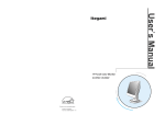
INSTRUCTION MANUAL
Color Camera
MODEL
ICD-525
ICD-525-TDN
OUTDOOR USE WARNING
WARNING – TO PREVENT FIRE OR
ELECTRIC SHOCK, DO NOT EXPOSE
THIS APPLIANCE TO RAIN OR
MOISTURE.
e
co
s
The apparatus shall not be exposed to
dripping or splashing and that no
objects filled with liquids, such as
vases, shall be placed on the
apparatus.
c
produ
t
Ikegami Tsushinki Co., Ltd.
Thank you for choosing this Ikegami ICD-525 Camera.
Please read this Instruction Manual carefully to keep your Ikegami camera at
peak performance for longer service period.
This unit is a box -type 1 CCD (1/3” ) color camera which has also switchable
monochrome mode from color mode for low light condition (as night).
Contents
Page
1.
2.
3.
4.
5.
Caution for Usage of Camera ..........................................................1
General ............................................................................................2
Future ...............................................................................................2
Name and Function of Each Part........................................................ 4
Connection .......................................................................................6
5-1. Power cable (AC24V IN/DC12V IN) ..........................................6
5-2. VIDEO OUT cable (VIDEO OUT) .............................................6
6. Operation .........................................................................................7
6-1. User Setup ................................................................................7
6-2. Names and functions of the setup buttons ...............................7
6-3. Setup mode procedures ...........................................................7
7. Focus EZ function ..........................................................................18
7-1. Screen Displays ......................................................................18
8. Warranty and after sale service .....................................................19
9. Specifications .................................................................................20
10.External Appearance .....................................................................22
11.Setup Flow Chart ...........................................................................23
The exclamation point within an equilateral triangle is intended to alert the user
to the presence of important operating and maintenance (servicing) instructions
in the literature accompanying the appliance.
NOTE:
This equipment has been tested and found to comply with the limits for a Class A
digital device, pursuant to part 15 of the FCC Rules. These limits are designed to
provide reasonable protection against harmful interference when the equipment is
operated in a commercial environment. This equipment generates, uses, and can
radiate radio frequency energy and, if not installed and used in accordance with
the instruction manual, may cause harmful interference to radio communications.
Operation of this equipment in a residential area is likely to cause harmful interference
in which case the user will be required to correct the interference at his own expense.
CAUTION;
ANY CHANGES OR MODIFICATIONS NOT EXPRESSLY APPROVED BY THE PART
RESPONSIBLE FOR COMPLIANCE COULD VOID THE USERS AUTHORITY TO
OPERATE THE EQUIPMENT.
Instructions for Disposal of Electrical and Electronic Equipment in
Private Households
Disposal of used Electric and Electronic Equipment
(Applicable in the European Union and other European countries with
separated waste disposal and collection methods)
This symbol on the product, or in the related documents in the package,
indicates that this product shall not be treated as normal household waste.
Instead, it should be taken to a proper applicable collection point or depot for
the recycling of electric and electronic equipment.
By ensuring this product is disposed of correctly, you will help prevent possible negative
consequences for the environment and human health, which could otherwise be caused
by inappropriate waste handling of this product. The recycling of materials will help to
conserve natural resources.
For more detailed information about recycling of this product, please contact your local city
authority, your household waste disposal service or the place where you purchased the
product.
IMPORTANT SAFETY INSTRUCTIONS
1) Read these instructions.
2) Keep these instructions.
3) Heed all warnings.
4) Follow all instructions.
5) Do not use this apparatus near water.
6) Clean only with a dry cloth.
7) Do not block any of the ventilation openings. Install in accordance with
the manufacturer's instructions.
8) Do not install near any heat sources such as radiators, heat registers,
stoves, or other apparatus (including amplifiers) that produce heat.
9) Do not defeat the safety purpose of the polarized or grounding type
plug. A polarized plug has two blades with one wider than the other. A
grounding type plug has two blades and a third grounding prong. The
wide blade or the third prong is provided for your safety. When the
provided plug does not fit into your outlet, consult an electrician for
replacement of the obsolete outlet.
10) Protect the power cord from being walked on or pinched particularly at
plugs, convenience receptacles, and the point where they exit from the
apparatus.
11) Only use the attachments/accessories specified by the manufacturer.
12) Use only with a cart, stand, tripod, bracket, or table specified by the
manufacturer, or sold with the apparatus. When a cart is used, use caution
when moving the cart/apparatus combination to avoid injury from tip-over.
13) Unplug this apparatus during lightning storms or when unused for long
periods of time.
14) Refer all servicing to qualified service personnel. Servicing is required
when the apparatus has been damaged in any way, such as power supply
cord or plug is damaged, liquid has been spilled or objects have fallen into
the apparatus, the apparatus has been exposed to rain or moisture, does
not operate normally, or has been dropped.
15) CAUTION - These servicing instructions are for use by qualified service
personnel only. To reduce the risk of electric shock, do not perform any
servicing other than that contained in the operating instructions unless
you are qualified to do so.
CAUTION
Danger of explosion if battery is incorrectly replaced.
Replace only with the same or equivalent type.
1. Caution for Usage of Camera
● Do not expose the camera/internal mechanism in the water/rain
splashed and/or moisture environment.
● Do not use the camera where the ambient temperature under -10
Celsius or over 50 Celsius. The image and component parts of camera
may be adversely affected and/or the camera may not function
correctly.
● Do not remove the camera case, unless it is absolutely necessary for
installing and/or adjusting the camera. The precision electrical and
electronic components parts are inside the camera. The unneeded
removing case is causing fault the camera, and/or accident (e.g.
electric shock).
● Power off the camera before installing and electrical connection the
camera.
● Do not drop camera and/or give the shock on camera which are in
transit.
● Do not touch the surface of Image Sensor with hand/fingers.
● Do not aim the camera at Sun.
● In case under high temperature condition, it may appear the FPN (Fixed
Pattern Noise) like rough on picture of camera. It is caused to Image
Sensor characteristic, not indicate a technical problem.
● If the camera shoot the fine stripes object, it may appear the colored
Interference fringe (Moire) on picture of camera. It is not indicate a
technical problem.
1
2. General
This color camera is provided with a 1/3-inch approx. 480,000 pixels
CCD sensor and equipped with the color/black-and-white picture out put
switching. This camera produce the high quality color picture in a day light
condition, and high sensitivity picture in the night.
This CCTV camera features wide dynamic range, high sensitivity and high
resolution, and is equipped with Auto iris control function (can be selected
suited auto iris lens) and other functions. The ICD-525 is best suited for
general surveillance.
3. Future
(1) High-quality picture and high resolution
The high resolution of a horizontal resolution of 700 TV lines is assured.
The camera is designed for smear-free imaging and low noise. The
well-designed DSP, Digital Signal Processor, effectively enhances
details, which achieves crisp and sharp images with a high signal-tonoise ratio.
(2) Day/Night change-over function
Depending on the surrounding brightness, the system automatically
switches over images from high-quality color images in the day time
to noise-reduced black and white images in the nighttime, always
providing clear images around the clock.
(3) Wide Light Dynamic Range (WDR)
The WDR function provides for very effective compensation of high light
and dark areas in screen. This situation may occur generally outside or
viewing from indoor to outdoor scenes. Even in large light fluctuations,
bright-and-dark subjects can be captured and viewed clearly with a
natural appearance.
(4) Automatic white balance (ATW: Automatic Tracking White Balance Control)
Thanks to the automatic follow-up white balance control (ATW), the
white balance adjusts itself no matter how great the subject's color
temperature fluctuates.
(5) AES (Automatic electronic shutter)
The AES function with sensitivity ratio of 1:1600 is incorporated for smooth
sensitivity control by variable step control, allowing the stable video output
equivalent to F1.5 to F50 Auto Iris to be obtained, even with a fixed iris lens.
2
(6) Automatic iris control
This function is available control voltage for DC type auto iris lens.
Almost all types of DC control auto iris CCTV lenses can be used.
(7) Lens flange back focus adjustment
An easy adjustment can be done by a rotating lens mount mechanism,
this may be useful to fix/use auto iris zoom lenses.
(8) FOCUS EZ function
The level indicator is displayed to allow immediate judgment of focal
point. In addition, the focus of the auto-iris lens is released to allow
easy focusing without worrying about the depth of field even in a bright
environment during the day light.
(9) Optimum Monitor Output Select function
The optimum picture quality can be obtained with this unique function
for CRT or LCD monitors. Sometimes, LCD, Liquid Crystal display type,
Flat Screen.
Monitor with digital process function shows different display
reproduction characteristics and you may choose this output selection
to have the best pictures on the monitor screen. The level indicator is
displayed to allow immediate judgment of focal point. In addition, the
focus of the auto-iris lens is released to allow easy focusing without
worrying about the depth of field even in a bright environment during
the day light.
3
4. Name and Function of Each Part
4
2
3
7
1
8
5
LENS
POWER
VIDEO OUT
10
U
6
SET UP
AC24V 50/60Hz 230mA
∼
R
L
E
− +
DC12V 240mA
9
4
D
① Lens Mount (CS Mount)
Lens fixing Mount for various CS Mount lens (C-mount adaptor can be
attached).
② Fixing screw for Lens flange back focus adjustment
Loose the screw before flange back focus adjustment, and tight after
this adjustment.
③ Flange back focus adjustment mechanism
If it is unfocused picture even after adjust the focus ring of lens, flange
back focus adjustment shall be done (adjust the depth between lens
fixing surface and CCD image capture face).
④ The screw holes for camera holder/mount
These screw holes are for fixing the camera holder for wall or ceiling,
also tripod for photo camera.
The fixing screw length for camera holder and tripod should be less
than 5.5mm as follows (1/4”-20UNC) size screw.
⑤ Video Output connector (Video out)
Video signal out connector for monitor/switcher.
⑥ Power Input connector (non polarity)
Enter the power of AC24V IN (±10%)/DC12V (DC10.5V to 15V).
⑦ Power indicator
LED: It is lit green when power on.
⑧ Auto iris lens connector (for DC control iris lens only)
This connector is used for connecting DC Iris control cable plug
(Applicable E4-191J-100 or equivalent) for DC type auto iris lens.
● DC Iris System
— Connector cable leads —
Auto iris lens
4
2
1. Damping coil (-)
2. Damping coil (+)
3. Driving coil (+)
3
1
4. Driving coil (-)
* Connect the leads as shown above.
Please refer also to the instruction manual
3
of lens to be used.
⑨ to ⑩ Button for Set up
1
4
See page 7 “Operation”.
2
Connector pin assignment
5
5. Connection
5-1. Power cable (AC24V IN/DC12V IN)
● AC24V (±10%), DC12V Connector (10.5V to 15V):
Connect to DC power supply.
5-2. VIDEO OUT cable (VIDEO OUT)
The VIDEO OUT connector is output only camera Video signal for monitor,
switcher and etc. Connect to video in connector for monitor, switcher and
etc with BNC coaxial cable.
6
6. Operation
6-1. User Setup
The ICD-525 camera is provided with user setup function for picture
quality, and camera ID. The setup menu is a tree type on-screen-display.
When installing the camera it is possible to set up the various functions.
6-2. Names and functions of the setup buttons
U
U
D
R
L
E
To select setup parameters
SET UP
(Cursor Up and Down)
To change the setup
L
R
parameter value/item
To get in or get out Set up
E
mode, and to enter and
D
execute procedures.
*To get into Setup mode ,hold “E” button more than 2 seconds.
6-3. Setup mode procedures
Hold down the enter “E” button longer than 2 seconds, and the setup
menu screen appears on screen. A blue highlighted (cursor) item is now
selected (other item is selectable with “U” or “D” button).
Use the “L” or “R” buttons to change the value or select the set item of
setup parameters.
7
6-3-1. SET UP MENU 1/3 (LANGUAGE selected“ ENGLISH”)
EXIT : Quit the Menu and save the changed value/set data on Menu.
RESET : Default the all data (back to factory setup condition).
SETUP MENU
1. PAGE
2. LENS
3. EXPOSURE
4. BACKLIGHT
5. WHITE BAL
6. DNR
7. DAY/NIGHT
1/3
DC
EXIT
RESET
WDR
ATW
ON
AUTO
1. PAGE
Used to change the page of Setup menu.
2. LENS
DC/MANUAL : Select used lens type.
Usually set “DC”.
1. IRIS : Adjust the iris level for DC
control iris lens. (value : 0 to 31)
2. SPEED : Adjust the control speed
for DC iris lens. (value : 0 to 255)
3. RETUEN : Back to SETUP MENU
screen.
DC LENS
1. IRIS
2. SPEED
3. RETURN
006
034
If it is changed the value for above DC LENS value, it may cause the
picture brightness changing. Do not touch this adjustment item except
service engineer.
3. EXPOSURE
1. SHUTTER : Select the Shutter
mode.
−−− : Fix the shutter speed 1/60
second.
A.FLK : Select when the flicker on
picture.
ESC : Select when manual iris lens
is used.
EXPOSURE
1. SHUTTER
2. AGC
3. SENS-UP
4. RETUEN
―――
MIDOLE
AUTO
Do not select “AES” when DC auto iris lens is attached and used.
Manual : Set the fixed shutter speed 1/60 to 1/120000 second.
8
2. AGC(AUTO GAIN CONTROL): Select/set the gain level between
OFF, LOW, MIDLOW, MIDDLE, MIDHIGH, HIGH.
High level AGC gain can display brighter picture, although noise
can more readily increase.
3. SENS-UP : Automatically up the brightness of picture where dark
place like night condition by electric charge accumulation.
OFF : Inactivate SENS-UP function.
AUTO : Activate SENS-UP function.
1. AUTO : Set the sensitivity up level x2, x4, x6,x 8, x10, x12,
x14, x16, x24, x32.
*The high value can display
brighter picture, although
the blur of moving object
will be appear .
*During this setup the
picture will be noisy and/or
whitish, it is not indicate a
technical problem.
LIMIT
1. AUTO
2. RETURN
X2
2. RETURN : Back to SETUP MENU screen. From below
“RETURN” explanation is omitted.
4. BACK LIGHT
OFF : No function of BLC.
BLC : Usual function of BLC.
WDR SETUP
WDR : If the picture shows still white
saturation on it and see hard for
1. LIMIT
HIGH
details of picture even set above
2. LEVEL
012
3. ANTI ROLLING
OFF
“BLC” on camera, set “WDR”.
4. RETURN
1. LIMIT : Select and set the
Sensitivity for WDR LOW, MIDLOW,
MIDDLE, MIDHIGH, HIGH
2. LVEL : Set the brightness of WDR
icture. (value 0 to 20)
3. ANTI ROLLING : Reduce the ”Color rolling“ around the fluorescent
lamp on picture.
OFF : Inactivate “ANTI ROLLING” function.
ON : Activate “ANTI ROLLING” function.
9
-WDR effect
WDR ON
WDR OFF
1. “WDR” is functioned with “SHUTTER” mode set (----).
2. “WDR” function is influenced the size of high light area.
The camera installing place and angle shall considered this point.
3. Color rolling phenomenon is colored picture around the fluorescent
lamp randomly appeared. It is caused flicker of fluorescent lamp by
Alternate current power as usual.
5. WHITE BAL (WHITE BALANCE)
ATW
: Auto tracking white balance for scene.
1. SPEED : Set the speed of tracking
ATW SETUP
speed for auto white balance. The
1. SPEED
040
value is 0 to 255.
2. ENVIRONMENT
OUTDOOR
3.
RETURN
2. ENVIRONMENT
INDOOR : Select when indoor
scene/object is mainly for camera.
OUTDOOR : Select when outdoor
scene/object is mainly for camera.
Out door scene condition for is changing harder than indoor
condition, as influence weather sun light (changed time go by).
Thus set “OUTDOOR” for outdoor use camera.
AWC PUSH : This is so-called “one-push automatic white balance
control”.
Shoot the white subject and press the “E” button, and the
white balance will be adjusted. After this adjustment, if
the color temperature for subject is changed, this white
balance data is not changed and not followed. This
function shall be used for same lighting condition for
subject.
MANUAL : The white balance is adjusted by manually. Select and
press E button, then left screen displayed.
10
1. RED : Adjust the reddish color.
2. BLUE : Adjust the bluish color.
WB MANUAL
1. RED
2. BLUE
3. RETURN
053
028
The ATW mode may not work correctly under following lighting conditions.
In this case, select AWC and adjust the white balance.
① The lighting condition (color temperature) is out of control span of ATW
(e.g. clear blue sky, before/after Sun rise/Sun set)
② Too low lighting condition for subject.
③ The white balance function may not work of stability when the camera
aim the fluoresce lamp or under extremely/rapidly change lighting
condition.
6. DNR (Digital Noise Reduction)
OFF : No function of DNR.
ON : Function of DNR.
1. LEVEL: Adjust the noise reduction
Level. Adjusting value 0 to 20.
DNR SETUP
1. LEVEL
2. RETURN
003
Note: Higher reduction value may caused
the blur phenomenon of moving
subject on picture.
7. DAY/ NIGHT
AUTO : Automatic switching is made high quality color picture in the
day, and high sensitivity monochrome pictures at night.
1. DWELL TIME : Adjust the transition
DAY/NIGHT SETUP
time between DAY and NIGHT
1. DWELL TIME
005
mode. Adjusting value 0 to 20.
2. RETURN
COLOR : COLOR Mode fixed.
B/W
: Monochrome Mode fixed.
11
6-3-2. SET UP MENU 2/3 (LANGUAGE selected“ ENGLISH”)
SETUP MENU
1. PAGE
2. IMAGE ADJ
3. PICTURE ADJ
4. CAMERA TITLE
5. D-ZOOM
6. MOTION DET
7. PRIVACY MASK
2/3
EXIT
RESET
OFF
OFF
OFF
1. PAGE
Change the page of Setup menu.
2. IMAGE SETUP
1. FREEZE
IMAGE SETUP
OFF : Inactivated freeze function.
1. FREEZE
OFF
ON : The picture is frozen.
2. MIRROR
OFF
2. MIRROR
3. RESOLUTION
NOMAL
4. PEDESTAL
7.5IRE
OFF : Output normal picture.
5. RETURN
V-FLIP : Inverse Up/Down side of
picture.
H-FLIP : Inverse Left/Right side of
picture.
HV-FLIP : Rotate 180 degree of picture.
3. RESOLUTION
NORMAL : Set the resolution of picture as usual.
HIGH : Set the resolution of picture as high resolution.
4. PEDESTAL
7.5IRE : Set the Pedestal level 7.5IRE of Video signal.
0 IRE : Set the Pedestal level 0IRE of Video signal.
3. PICTURE SETUP
1. R-GAIN :Adjust reddish of picture
PICTURE SETUP
(value 0 to 15).
2. B-GAIN : Adjust bluish of picture
1. R-GAIN
010
2.
B-GAIN
010
(value 0 to 15).
3. HUE
008
3. HUE: Adjust hue of picture (value 0 4. CONTRAST
035
5.
SHARPNESS
008
to 15).
6. COLOR GAIN
MIDDLE
4. CONTRAST:Adjust contrast of
7. GAMMA
0.55
8. RETURN
picture (value 0 to 63).
5. SHARPNESS: Adjust sharpness of
picture (value 0 to 15).
12
6. COLOR GAIN: Adjust/set the color level of picture.
OFF: (No gain up the color level)/LOW/ MIDDLE/ HIGH
7. GAMMA: Adjust/set the Gamma correction value of picture
between 0.38 / 0.42 / 0.45 / 0.50 / 0.55 / 0.63 / 0.71 / 0.83 / 1.0.
Note :The lower value for GAMMA above, realize to display more
brighter for dark section of picture, but it cause noise level
up bit and reduce the graduation for bright section of picture.
4. CAMERA TITLE
Used to set the camera /site name, allows up to.52 alphanumeric (26
alphanumeric /1 line, 52 alphanumeric /2 line on screen).
OFF : No display on screen.
ON : Display on screen.
● Setting TITLE
CAMERA TITLE : Set “ON” and press
CAMERA TITLE
“E” button for display right shown screen.
Select the needed character with L, R, U,
D button and press “E” button. And the
ABCDEFGHIJKLMNOPQRSTUV
cursor for TITLE is stepped to next letter
WXYZ0123456789-!”#$%&’
()_`,¥:;<=>?@\^*.x+/
position.
● Erase 1 letter by 1 letter
←→↑↓ CLR POS
Move the cursor with ←→ on erasing
RETURN
needed letter and “CLR” + “E” button.
● POSITION
Move the cursor on “POS” and press “E “button then Title displayed on
screen.
Set the Title display position with L, R, U, D button and determine press
“E”.
No display the TITLE on screen when set “OFF” for CAMERA TITLE.
5. D–ZOOM (Digital Zoom Up)
Set the Zoom up magnify power for center of picture.
OFF : Inactivate D-Zoom function (same as with “ON” SET x1).
ON : D-Zoom functioned.
1. Set the magnify power between x1 to x32.
If “DIS” stabilizer (6-3-3 item3 page 22) is set ON, D-ZOOM is not functioned.
6. MOTION DET (MOTION DETECTION)
Detect the changing of picture (moving subject) function.
OFF : Inactivate MOTION DET function.
ON : MOTION DET functioned.
13
1. DETECT SENSE : Adjust the
MOTION DET
detect sensitivity for moving
1. DETECT SENSE
111
subject. Higher value setting, more 2. BLOCK DISP
OFF
3. DETECT AREA
sensitivity of detection (value 0 to
4. MONITOR AREA
127).
5. RETURN
2. BLOCK DISP : Display the block
screen for detected Area of picture.
OFF : Inactivate BLOCK DISP
function.
ON : Display the block screen for detected area of picture.
3. DETECT AREA : Set the detection area on picture (8 x12 blocks).
Detection area picture is inverted negative picture.
The cursor on picture (block) can be moved with L, R, U, D button,
and determined the detection area on picture by pressing “E”
button.
4. MONITOR AREA : Set non detect
MONITOR AREA
Area (Up to 4 areas)on picture.
1. AREA SEL
1/4
1. AREA SEL : Set 4 non detect
2. MODE
OFF
003
areas. 1/4 Red frame, 2/4 Green, 3. TOP
4. BOTTOM
012
3/4 Violet, 4/4 Yellow.
5. LEFT
002
2. MODE : Active non detect area. 6. RIGHT
005
7. RETURN
3. TOP : Set top frame position.
4. BOTTOM : Set bottom frame
position.
5. LEFT : Set left frame position.
6. RIGHT : Set right frame position.
Selection of up and down (0 to 15).
Selection of the right and left (0 to 23).
7. PRIVACY MASK
Set the privacy mask up to 15 masks on picture.
1. AREA : Select the setting privacy
PRIVACY MASK
mask between 1/15 to 15/15.
1. AREA
1/15
2. MODE : Set privacy mask display or 2. MODE
OFF
3. POSITION
non display on picture.
4. COLOR
OFF : No display the privacy mask. 5. MASK TONE
6.
MOSAIC
ON : Display the privacy mask, and
7. RETURN
below setting is valid.
3. POSITION : Set the position and
size for privacy mask following sub menu screen.
14
4. COLOR : Select/set the coloring for privacy masking area.
The color can be selected between 8 colors WHITE, BLACK,RED,
GREEN, BLUE, YELLOW, CYAN, MAGENTA.
5. MASK TONE : Select/set the translucent ratio of privacy mask.
0.00 (clear: no displayed masking area except ON set of
MOSAIC), 0.50, 0.75, 1.00 (opaque for behind picture).
6. MOSAIC : Mosaic display for privacy mask area on picture except
set 1.00 for above MASK TONE.
− : Invalid Mosaic setting (set 1.00 for above MASK TONE).
OFF : No display mosaic privacy masking area.
ON : Display mosaic privacy masking area.
15
6-3-3. SETUP MENU 3/3 (LANGUAGE selected“ ENGLISH”)
SETUP MENU
1. PAGE
2. MONITOR
3. DIS
4. SYNC
5. VIDEO ADJ
6. LANGUAGE
3/3
LCD
OFF
INT
EXIT
RESET
ENGLISH
1. PAGE
Change the page of Setup menu.
2. MONITOR
The optimum picture quality can be selected according to the monitor
used.
LCD : Set. when the camera video signal is connected LCD monitor.
CRT : Set when the camera video signal is connected with CRT (cathode
ray tube)monitor.
3. DIS (Digital Image Stabilizer)
Stabilize the shaking picture on screen caused camera (housing)
shacking by wind e.g.
OFF : Invalid DIS function.
ON : Valid DIS function.
-The resolution of picture is reduce for using part of function Digital Zoom.
-This DIS may not functioned under low light condition for subject.
-This DIS may not functioned for simple subject like Sky, white wall.
-When DIS is set ON, invalidated the Digital Zoom and MOTION
DETECTION function.
4. SYNC (SYNCHRONIZATION SYSTEMS)
Select the synchronization system either INT (by Internal crystal OSC)
or LL (by AC power line frequency).
Especially using this camera in Japan, the “INT” shall be selected.
Because there are 50Hz power system and 60Hz power system in
Japan.
-This camera shall be set “INT” on this menu setup.
-If it is set “LL”, it may caused unstable picture on screen.
16
5. VIDEO ADJ
VIDEO SETUP
Set the each level of video signal.
1. SYNC LEVEL
020
1. SYNC : Adjust the Sync signal level 2. BURST LEVEL
015
3. CLIP LEVEL
020
(value 0 to 40).
4. RETURN
2. BURST : Adjust the Burst signal
level (value 0 to 30).
3. CLIP : Adjust the Video signal level
(value 0 to 40).
6. LANGUAGE
Select the language to display the SETUP MENU.
: In Japanese SET UP MENU.
日本語
ENGLISH : In English SET UP MENU.
17
7. Focus EZ function
7-1. Screen Displays
FOCUS EZ is a function to support focus adjustment. A focus indicator
displayed on the screen can be used to confirm the focus conditions. In
case of auto-iris, it is possible to open the lens aperture forcibly for a set
time period to carry out focus adjustment without worrying about field of
depth even in a bright environment during the day. (The camera sensitivity
is adjusted automatically, and there is no influence on the displayed
image).
Press the U button for over two seconds to start FOCUS EZ and go to the
focus adjustment screen.
FOCUS EZ can not be started in the SETUP mode.
Focus adjustment screen
Focus EZ
Light-measuring
area on picture
Focus
Indicator
Focus condition
While viewing the focus indicator on the focus adjustment screen, it
is possible to adjust the focus. Displayed the focus indicator is shown
the present focus condition. Adjust the focus so that the focus indicator
reaches the Maximum point.
Pressing the D button once during FOCUS EZ operation terminates
FOCUS EZ.
If the camera shoot the monotonous subjects like Sky, white wall, it may
caused no extending the Focus indicator.
This does not indicate a malfunction of camera.
18
8. Warranty and after sale service
A warranty accompanies this product. Read and fill out the warranty card
that you have received at your dealer. Keep this card in a safe place.
● Please consult Ikegami Electronics (U.S.A.) Inc. or Ikegami Electronics
(Europe) GmbH or your dealer for full warranty information. Your dealer
will repair or replace free of charge within the warranty period according
to the warranty coverage.
● For repairs after the expiration of the warranty period, consult your
dealer or sales representative. It will first be judged whether the fault is
repairable or not. Charged servicing will then be made upon request of
the user.
● Before you ask for servicing, please ensure you read the Instruction
Manual. If the unit still fails, take note of the model number, date of
purchase, problem, etc. in detail, and inform your dealer or sales
representative.
● If you have questions about the after-sale service, contact your dealer
or sales representative.
* We suggest you ask for preventive inspection as soon as possible.
19
9. Speci¿cations
(1)
(2)
(3)
(4)
Image Sensor:
Pixel Number:
Scanning system:
Sync system
1/3-inch CCD sensor
NTSC: 976 (H) × 494 (V), Approx.480,000 pixels
NTSC: 525 lines/ 59.94Hz, 2:1 interlace
INT (Crystal-lock), or
LL (line lock /phase adjustable): LL is not
usable where 50Hz power frequency or DC
12V power driven.
(5) Video output:
VBS 1.0Vp-p/75 :
(6) Resolution:
Horizontal: Over 700TV lines (Highresolution mode, rating illumination)
(7) S/N Ratio:
Over 52dB (p-p/rms)
0.22Lx/F1.2 (SENS-UP: OFF, VBS output: 50%)
(8) Minimum illumination:
0.007Lx/F1.2 (SENS-UP: x32, VBS output: 50%)
(9) Day/Night switching:
ICD-525
: Digital Day/Night
ICD-525-TDN : True Day/Night
(10) Wide Dynamic Range:
LOW/MIDLOW/MIDDLE/MIDHIGH/HIGH
Selectable from 6 steps above.
(11) AGC:
OFF/LOW/MIDLOW/MIDDLE/MIDHIGH/
HIGH Selectable from 6 steps
(12) Electronic Sensitivity Control: Built in, ON(AUTO)/OFF Selectable
Maximum 32 times
(13) White Balance Cont.:
ATW/AWC/MANUAL Selectable
(14) DETAIL correction:
Built in (SHARPNESS function)
(15) Noise Reduction:
Built in, ON/OFF Switchable (NDR function)
(16) AES:
Built in
(17) Privacy Mask setting:
Built in, (Up to 15 areas)
(18) MIRROR:
Built in, OFF/ H / V / H&V Selectable
(19) Motion Detection:
Built in, ON/OFF Switchable
(20) Digital Zoom:
Built in, ON/OFF Selectable (x32 Maximum)
(21) Focus adjust support:
Built in, (FOCUS EZ function)
(22) Image Stabilizer:
Built in, (DIS function)
(23) Monitor output Selection: CRT/LCD Switchable
(24) Camera ID:
Up to 26 alphanumeric/1 line, 2 lines
(25) Local Setup :
Use the buttons on the rear panel of camera
and operate the screen Setup menu display.
(26) Lens Mount:
CS Mount
(C-mount adapter attachment possible)
(27) Lens flange back Adjustment: Built in
20
(28) Power Requirement:
(29) Current Consumption:
AC24V±10%, 60Hz / DC12(10.5 to 15V)
AC24V: 3W
DC12V: 3W
(30) Operating Temperature
and Relative Temperature: -10 ∼ +50℃ / 30 ∼ 90%RH (No Condensation)
(31) Camera Mount:
1/4”-20UNC (this mount part is changeable
to fix on Top or Bottom side of camera.
(32) Outer dimensions:
60mm (W) × 58mm (H) × 70mm (D)
(No protrusion included)
(33) Weight:
Approx. 240g
(34) Input/Output connectors: VIDEO OUT
BNC
AC24V/DC12V IN 2-Pin terminal block
(35) Supplied accessories:
Instruction Manual
Allen wrench (for flange back adjustment)
Power input connector
21
10. External Appearance
(22)
14±0.5
2-1/4"-20UNC
(6.5)
70±3
60±3
LENS
POWER
58±3
VIDEO OUT
U
SET UP
AC24V 50/60Hz 230mA
∼
R
L
E
− +
DC12V 240mA
22
D
㪪㪜㪫㪬㪧㩷㪤㪜㪥㪬
㪧㪬㪪㪟㩷㪪㪜㪫
㪝㪦㪩㩷㪘㩷㪮㪟㪠㪣㪜
23
㪊㪅㪧㪠㪚㪫㪬㪩㪜㩷㪘㪛㪡㸣
㪉㪅㪠㪤㪘㪞㪜㩷㪘㪛㪡㸣
㪉㪆㪊
㪘㪬㪫㪦㸣
㪚㪦㪣㪦㪩
㪙㪆㪮
㪎㪅㪛㪘㪰㪆㪥㪠㪞㪟㪫
㪈㪅㪧㪘㪞㪜
㪦㪝㪝
㪦㪥㸣
㪘㪮㪚㩷㪧㪬㪪㪟㸣
㪤㪘㪥㪬㪘㪣㸣
㪘㪫㪮㸣
㪍㪅㪛㪥㪩
㪌㪅㪮㪟㪠㪫㪜㩷㪙㪘㪣
㪋㪅㪙㪘㪚㪢㪣㪠㪞㪟㪫
㪦㪝㪝
㪙㪣㪚
㪮㪛㪩㸣
㪛㪚
㪤㪘㪥㪬㪘㪣
㪉㪅㪣㪜㪥㪪
㪊㪅㪜㪯㪧㪦㪪㪬㪩㪜㸣
㪈㪆㪊
㪈㪅㪧㪘㪞㪜
㪫㪦㪧
㪇㪇㪇㪄㪉㪌㪌
㪉㪅㪪㪧㪜㪜㪛
㪦㪝㪝
㪣㪦㪮
㪤㪠㪛㪣㪦㪮
㪤㪠㪛㪛㪣㪜
㪤㪠㪛㪟㪠㪞㪟
㪟㪠㪞㪟
㪦㪝㪝
㪘㪬㪫㪦㸣
㪉㪅㪘㪞㪚
㪊㪅㪪㪜㪥㪪㪄㪬㪧
㪇㪇㪇㪄㪇㪉㪇
㪦㪝㪝
㪦㪥
㪉㪅㪣㪜㪭㪜㪣
㪊㪅㪘㪥㪫㪠㩷㪩㪦㪣㪣㪠㪥㪞
㪦㪬㪫㪛㪦㪦㪩
㪠㪥㪛㪦㪦㪩
㪉㪅㪜㪥㪭㪠㪩㪦㪥㪤㪜㪥㪫
㪦㪝㪝
㪭㪄㪝㪣㪠㪧
㪟㪄㪝㪣㪠㪧
㪟㪭㪄㪝㪣㪠㪧
㪥㪦㪩㪤㪘㪣
㪟㪠㪞㪟
㪎㪅㪌㩷㪠㪩㪜
㪇㩷㪠㪩㪜
㪇㪇㪇㪄㪇㪈㪌
㪉㪅㪤㪠㪩㪩㪦㪩
㪊㪅㪩㪜㪪㪦㪣㪬㪫㪠㪦㪥
㪋㪅㪧㪜㪛㪜㪪㪫㪘㪣
㪈㪅㪩㪄㪞㪘㪠㪥
㪌㪅㪩㪜㪫㪬㪩㪥㸣
㪦㪝㪝
㪦㪥
㪇㪇㪇㪄㪇㪊㪇
㪈㪅㪝㪩㪜㪜㪱㪜
㪉㪅㪩㪜㪫㪬㪩㪥㸣
㪈㪅㪛㪮㪜㪣㪣㩷㪫㪠㪤㪜
㪉㪅㪩㪜㪫㪬㪩㪥㸣
㪈㪅㪣㪜㪭㪜㪣
㪇㪇㪇㪄㪇㪉㪇
㪇㪇㪇㪄㪉㪌㪌
㪉㪅㪙㪣㪬㪜
㪊㪅㪩㪜㪫㪬㪩㪥㸣
㪘㪮㪚㸢㪪㪜㪫
㪇㪇㪇㪄㪉㪌㪌
㪈㪅㪩㪜㪛
㪊㪅㪩㪜㪫㪬㪩㪥㸣
㪇㪇㪇㪄㪉㪌㪌
㪈㪅㪪㪧㪜㪜㪛
㪋㪅㪩㪜㪫㪬㪩㪥㸣
㪣㪦㪮
㪤㪠㪛㪣㪦㪮
㪤㪠㪛㪛㪣㪜
㪤㪠㪛㪟㪠㪞㪟
㪟㪠㪞㪟
㪈㪅㪣㪠㪤㪠㪫
㪋㪅㪩㪜㪫㪬㪩㪥㸣
㪄㪄㪄
㪘㪅㪝㪣㪢
㪜㪪㪚
㪤㪘㪥㪬㪘㪣㸣
㪈㪅㪪㪟㪬㪫㪫㪜㪩
㪊㪅㪩㪜㪫㪬㪩㪥㸣
㪇㪇㪇㪄㪇㪊㪈
㪈㪅㪠㪩㪠㪪
㪉㪥㪛
㪉㪅㪩㪜㪫㪬㪩㪥㸣
㪈㪅㪘㪬㪫㪦
㪈㪆㪍㪇
㪈㪆㪈㪇㪇
㪈㪆㪉㪌㪇
㪈㪆㪌㪇㪇
㪈㪆㪎㪇㪇
㪈㪆㪈㪇㪇㪇
㪈㪆㪈㪍㪇㪇
㪈㪆㪉㪌㪇㪇
㪈㪆㪌㪇㪇㪇
㪈㪆㪎㪇㪇㪇
㪈㪆㪈㪇㪇㪇㪇
㪈㪆㪊㪇㪇㪇㪇
㪈㪆㪍㪇㪇㪇㪇
㪈㪆㪈㪉㪇㪇㪇㪇
㪊㪩㪛
㬍㪉
㬍㪋
㬍㪍
㬍㪏
㬍㪈㪇
㬍㪈㪉
㬍㪈㪋
㬍㪈㪍
㬍㪉㪋
㬍㪊㪉
11. Setup Flow Chart
24
㪦㪝㪝
㪦㪥㸣
㪦㪝㪝
㪦㪥㸣
㪌㪅㪛㪄㪱㪦㪦㪤
㪍㪅㪤㪦㪫㪠㪦㪥㩷㪛㪜㪫
㪇㪇㪇㪄㪇㪊㪇
㪇㪇㪇㪄㪇㪋㪇
㪊㪅㪚㪣㪠㪧㩷㪣㪜㪭㪜㪣
㪋㪅㪩㪜㪫㪬㪩㪥㸣
㪇㪇㪇㪄㪇㪋㪇
㪉㪅㪙㪬㪩㪪㪫㩷㪣㪜㪭㪜㪣
㪉㪅㪩㪜㪫㪬㪩㪥㸣
㪈㪅㪧㪟㪘㪪㪜
㪇㪇㪇㪄㪈㪍㪇
㪦㪝㪝
㪦㪥
㪍㪅㪤㪦㪪㪘㪠㪚
㪎㪅㪩㪜㪫㪬㪩㪥㸣
㪇㪅㪇㪇
㪇㪅㪌㪇
㪇㪅㪎㪌
㪈㪅㪇㪇
㪌㪅㪤㪘㪪㪢㩷㪫㪦㪥㪜
㪋㪅㪚㪦㪣㪦㪩
㪮㪟㪠㪫㪜
㪙㪣㪘㪚㪢
㪩㪜㪛
㪞㪩㪜㪜㪥
㪙㪣㪬㪜
㪰㪜㪣㪣㪦㪮
㪚㪰㪘㪥
㪤㪘㪞㪜㪥㪫㪘
㪦㪝㪝
㪦㪥
㪉㪅㪤㪦㪛㪜
㪊㪅㪧㪦㪪㪠㪫㪠㪦㪥㸣
㪈㪆㪈㪌䌾㪈㪌㪆㪈㪌
㪈㪅㪘㪩㪜㪘
㪌㪅㪩㪜㪫㪬㪩㪥㸣
㪈㪅㪪㪰㪥㪚㩷㪣㪜㪭㪜㪣
㪋㪅㪪㪰㪥㪚
㪜㪥㪞㪣㪠㪪㪟
ᣣᧄ⺆
㪠㪥㪫
㪣㪣㸣
㪊㪅㪛㪠㪪
㪛㪜㪫㪜㪚㪫㩷㪘㪩㪜㪘
㩷㩷㩷㪜㪯㪠㪫䋺㪟㪦㪣㪛㩷㪜㪥㪫㪜㪩
㪊㪅㪛㪜㪫㪜㪚㪫㩷㪘㪩㪜㪘㸣
㪍㪅㪣㪘㪥㪞㪬㪘㪞㪜
㪦㪝㪝
㪦㪥
㪉㪅㪤㪦㪥㪠㪫㪦㪩
㪦㪝㪝
㪦㪥
㪋㪅㪤㪦㪥㪠㪫㪦㪩㩷㪘㪩㪜㪘㸣
㪇㪇㪇㪄㪈㪉㪎
㪉㪅㪙㪣㪦㪚㪢㩷㪛㪠㪪㪧
㬍㪈㪅㪈䌾㬍㪊㪉
㪇㪇㪇㪄㪇㪈㪌
㪇㪇㪇㪄㪇㪉㪊
㪇㪇㪇㪄㪇㪉㪊
㪋㪅㪙㪦㪫㪫㪦㪤
㪌㪅㪣㪜㪝㪫
㪍㪅㪩㪠㪞㪟㪫
㪥㪜㪯㪫䋺㪧㪬㪪㪟㩷㪜㪥㪫㪜㪩
㪜㪯㪠㪫䋺㪧㪬㪪㪟㩷㪜㪥㪫㪜㪩
㪇㪇㪇㪄㪇㪈㪌
㪊㪅㪫㪦㪧
㪎㪅㪩㪜㪫㪬㪩㪥㸣
㪦㪝㪝
㪦㪥
㪈㪆㪋䌾㪋㪆㪋
㪉㪅㪤㪦㪛㪜
㪈㪅㪘㪩㪜㪘㩷㪪㪜㪣
㪚㪘㪤㪜㪩㪘㩷㪫㪠㪫㪣㪜
㩷㩷㩷㪘䌾㪱䇮㪇䌾㪐䇮㪚㪦㪛㪜䇮㸠䇮㸢䇮㸡䇮㸣䇮
㩷㩷㩷㪚㪣㪩䇮㪧㪦㪪㸣䇮㪩㪜㪫㪬㪩㪥㸣
㪈㪅㪛㪜㪫㪜㪚㪫㩷㪪㪜㪥㪪
㪉㪅㪩㪜㪫㪬㪩㪥㸣
㪈㪅㪣㪜㪭㪜㪣
㪏㪅㪩㪜㪫㪬㪩㪥㸣
㪌㪅㪭㪠㪛㪜㪦㩷㪘㪛㪡㸣
㪊㪆㪊
㪣㪚㪛
㪚㪩㪫
㪈㪅㪧㪘㪞㪜
㪎㪅㪧㪩㪠㪭㪘㪚㪰㩷㪤㪘㪪㪢㸣
㪦㪝㪝
㪦㪥㸣
㪋㪅㪚㪘㪤㪜㪩㪘㩷㪫㪠㪫㪣㪜
㪦㪝㪝
㪣㪦㪮
㪤㪠㪛㪛㪣㪜
㪟㪠㪞㪟
㪍㪅㪚㪦㪣㪦㪩㩷㪞㪘㪠㪥
㪇㪅㪊㪏
㪇㪅㪋㪉
㪇㪅㪋㪌
㪇㪅㪌㪇
㪇㪅㪌㪌
㪇㪅㪍㪊
㪇㪅㪎㪈
㪇㪅㪏㪊
㪈㪅㪇
㪇㪇㪇㪄㪇㪈㪌
㪌㪅㪪㪟㪘㪩㪧㪥㪜㪪㪪
㪎㪅㪞㪘㪤㪤㪘
㪇㪇㪇㪄㪇㪈㪌
㪇㪇㪇㪄㪇㪍㪊
㪋㪅㪚㪦㪥㪫㪩㪘㪪㪫
㪇㪇㪇㪄㪇㪈㪌
㪊㪅㪟㪬㪜
㪉㪅㪙㪄㪞㪘㪠㪥
MEMO
MEMO
■ Ikegami Electronics (U.S.A.), Inc.
37 Brook Avenue, Maywood, N.J. 07607, U.S.A.
Phone: (201) 368-9171, FAX (201) 569-1626
www.Ikegami.com
or
■ Ikegami Electronics (Europe) GmbH
Ikegami Strasse 1, D-41460 Neuss, Germany
Phone : 02131-123-0, FAX 02131-102820
www.Ikegami.de
■ Ikegami Electronics U.K. Office:
Unit E1, Cologne Court, Brooklands Close,
Windmill Road, Sunbury-on-Thames,
Middlesex, TW16 7EB, U.K.
Phone:01932-769700 FAX 01-92-769710
www.Ikegami.co.uk
Ikegami Tsushinki Co., Ltd.
NNA005266-00