1
=$*&%('
Chapter
Wiring
1 Preparation
Preparation
1
Precautions
Preface
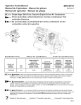
* Please review the content below to ensure safe and precise product usage.
I Safety Precautions
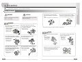
WARNING
Do not use pins or any sharp, pointy
objects to press buttons or to insert into
holes.
CAUTION
Neglect to follow directions can result in
injury or material loss.
Neglect to follow directions can result in
death or serious injury.
Do not clean using wet cloths or volatile
substances (e.g. alcohol, benzene, thinner).
It may cause product electric shock and/or fire.
Þ
It may cause product electric shock and/or fire.
Þ
WARNING
Do not disassemble, install or repair this
product on your own.
Contact the service center for any repair needs.
Unauthorized handling
may cause product
malfunction, electric
shock, and/or fire.
Þ
Do not place the product near a heat
source (e.g. heater) or source of moisture
(e.g. aquarium, humidifier).
Þ
After servicing, ask the service engineer to perform a safety inspection
It may cause product
malfunction and/or fire.
Þ
CAUTION
Do not subject the product to any heavy
shock such as striking with a hardobject
(e.g. hammer, etc.).
It may cause product
malfunction, electric
shock, and/or fire.
Þ
If the product emits a peculiar noise,
odour and/or smoke, immediately switch
off the power (ONT product connection) in
the power cabinet panel then
contact the service centre.
Do not allow water or other liquid to
enter the product interior.
It may cause product
electric shock and/or fire.
Þ
Do not allow water to enter the camera
interior when cleaning.
It may result in electrical
shock and/or fire.
Þ
Do not hang from or pull on the installed
Be careful when standing up after sitting
product.
under the installed product.
Take special care to
prevent such abuse
by small children as
injury may occur.
Þ
Þ
Head injuries may
occur from any
impact with the
installed product.
Make sure to pass the user manual onto the
new home owner/tenant when moving.
It can prevent any product misuse by the new
home owner/tenant.
Þ
Beware the risk of electric
shock and/or fire.
Þ
2
3
Chapter
Locating of controls
1 Preparation
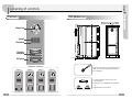
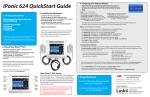
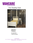
IFront Panel
I Side & Bottom Panel
Camera Lens
Speaker
Microphone
Directory/
Name plate
* Call button
* Organization of call buttons
SVM-0200
SVM-0400
SVM-0600
SVM-0800
Adjust the camera position to get a better view and
tighten the screws with a Philip (hex) screwdriver
before installation.
1. Press in the direction of arrow to remove the
transparent plate.
2. Fill in name or room number with an oilsoluble pen,
etc.
3. Attach the plate to the front panel.
4
5
Chapter
Installation
Wiring
1 Preparation
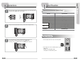
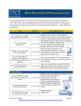
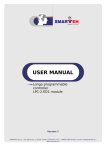
I Monitor Connection
Plug wires(from tenant monitor) into connectors on the camera
respectively according to illustrated diagrams as below.
Power Connection
Open Door Connection
Installation Method
1. It is recommended to mount the flush Box at the height of average adult’s eyelevel from the ground
2. Mount front panel on the flush Box with provided hexagonal screws.
3. Assemble each side mounting bracket on the front panel with provided hexagonal screws.
4. Leave the front panel unattached on the wall before you make sure all the stations have been
installed and wired properly.
Connection to VDP
No.
1
2
3
4
6
Color
Red
Blue
White
Black
Remark
POWER_ON
VOICE
VIDEO
GROUND
Note :
1. The connection between wires and connectors
should be completed in the reverse side of your
desired call buttons
2. No additional system set-up is necessary after
wiring
7
2
The monitor station sounds a melody and the indicator light of door camera flashes after
a visitor presses the “CALL” button of door camera
Pick up the monitor station handset to talk to your visitor after hearing the melody.
Specification
2 Usage
1
Chapter
Operations
I SVM-0200/0400/0600/0800 (Master Panel)
Remark
Specification
Power Source
Power Consumption
Display output
Maximum Wiring Distance
Minimum Illuminance
Temperature
Environment
Humidity
Dimension
Size
Weight
Installation
Regulated DC 12V
DC 12V, 330mA
Composite PAL
0.65(AWG22) , 50m
1 Lux
-20 °C ~ 55°C
Below 90% (relative)
123(W) x 308(H) x 18(D)(mm)
1Kg
Flush Mount Type
I Power Connection
3
If the optional electric door striker is installed it functions in the following way.
- To unlock the door during conversation, Press door “OPEN” button.
- The image on the screen disappears when door “OPEN” button is pressed.
1. Connect adaptor (DC 12 V / 1.2 A) to side of the product.
2. If the adaptor does not fit, use additional cable to connect.
[Cable speac]
Red Wire : + 12 V / Black Wire : GND
* DC adaptor is not included in the product
8
9
Chapter
Extension Panel
Installation/Wiring
3 Extension
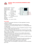
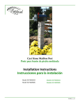
I Panel Combination
I Installation (Extension Panel with Jointers)
SVM-0800 + SVE-0400
SVM-0800 + SVE-0800
SVM-0800 + SVE-1200
[12 Buttons]
[16 Buttons]
[20 Buttons]
SVM-0800 + SVE-1600
SVM-0800 + SVE-2000
SVM-0800 + SVE-2400
I Wiring
[24 Buttons]
[28 Buttons]
[32 Buttons]
1. Put the wires into connectors between the modules.
2. Remove the stopper of each flush box.
3. Pass the wire(A) through the jointers and plug to connector(B)
10
11