1
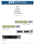
Model TIF 2000A
Digital Hybrid Telephone Line Interface
F.01U.193.286
Rev. 07
JANUARY/2012
ii
TIF-2000A
PROPRIETARY NOTICE
The product information and design disclosed herein were originated by and are the property of Bosch Security Systems, Inc.
Bosch reserves all patent, proprietary design, manufacturing, reproduction, use and sales rights thereto, and to any article disclosed
therein, except to the extent rights are expressly granted to others.
COPYRIGHT NOTICE
Copyright 2012 by Bosch Security Systems, Inc. All rights
reserved. Reproduction, in whole or in part, without prior written
permission from Bosch is prohibited.
WARRANTY AND SERVICE INFORMATION
For warranty and service information, refer to the appropriate web
site below:
RTSwww.rtsintercoms.com/warranty
RTSTWwww.rtstw.com/warranty
AudioComwww.telexaudiocom.com/warranty
RadioComwww.telexradiocom.com/warranty
THE LIGHTNING FLASH
AND ARROWHEAD WITHIN
THE TRIANGLE IS A
WARNING
SIGN ALERTING YOU OF
“DANGEROUS
VOLTAGE”
INSIDE THE
PRODUCT.
CAUTION: TO
REDUCE THE RISK
OF ELECTRIC
SHOCK, DO NOT
REMOVE COVER.
NO USER-SERVICABLE PARTS
INSIDE. REFER SERVICING TO QUALIFIED SERVICE
PERSONNEL.
THE EXCLAMATION POINT
WITHIN THE
TRIANGLE IS A
WARNING SIGN
ALERTING YOU
OF IMPORTANT
INSTRUCTIONS
ACCOMPANYING THE PRODUCT
SEE MARKING ON BOTTOM/BACK OF PRODUCT
Headsetswww.intercomheadsets.com/warranty
WARNING: APPARATUS SHALL NOT BE EXPOSED TO
DRIPPING OR SPLASHING AND NO OBJECTS FILLED
WITH LIQUIDS, SUCH AS VASES, SHALL BE PLACED ON
THE APPARATUS.
CUSTOMER SUPPORT
Technical questions should be directed to:
Customer Service Department
Bosch Security Systems, Inc.
12000 Portland Avenue South
Burnsville, MN 55337 USA
Telephone: 877-863-4169
Fax: 800-323-0498
[email protected]
WARNING: THE MAIN POWER PLUG MUST REMAIN
READILY OPERABLE
CAUTION: TO REDUCE THE RISK OF ELECTRIC SHOCK,
GROUNDING OF THE CENTER PIN OF THIS PLUG MUST
BE
MAINTAINED.
Technical Questions EMEA
Bosch Security Systems Technical Support EMEA
http://www.rtsintercoms.com/contact_main.php
WARNING: TO REDUCE THE RISK OF FIRE OR ELECTRIC
SHOCK, DO NOT EXPOSE THIS APPRATUS TO RAIN OR
MOISTURE.
DISCLAIMER
The manufacturer of the equipment described herein makes
no expressed or implied warranty with respect to anything
contained in this manual and shall not be held liable for any
implied warranties of fitness for a particular application or
for any indirect, special, or consequential damages. The
information contained herein is subject to change without
prior notice and shall not be construed as an expressed or
implied commitment on the part of the manufacturer.
Bosch Security Systems, Inc.
User Manual
WARNING: TO PREVENT INJURY, THIS APPARATUS MUST
BE SECURELY ATTACHED TO THE FLOOR/WALL/RACK IN
ACCORDANCE WITH THE INSTALLATION INSTRUCTIONS.
This product is AC
only.
F.01U.193.286
Rev. 07
TIF-2000A
iii
Important Safety Instructions
1.
Read these instructions.
2.
Keep these instructions.
3.
Heed all warnings.
4.
Follow all instructions.
5.
Do not use this apparatus near water.
6.
Clean only with dry cloth.
7.
Do not block any ventilation openings. Install in accordance with the
manufacturer’s instructions.
8.
Do not install near any heat sources such as radiators, heat registers, stoves, or
other apparatus (including amplifiers) that produce heat.
9.
Do not defeat the safety purpose of the polarized or grounding-type plug. A
polarized plug has two blades with one wider than the other. A grounding type
plug has two blades and a third grounding prong. The wide blade or the third
prong are provided for your safety. If the provided plug does not fit into your
outlet, consult an electrician for replacement of the obsolete outlet.
10. Protect the power cord from being walked on or pinched particularly at plugs,
convenience receptacles, and the point where they exit from the apparatus.
11. Only use attachments/accessories specified by the manufacturer.
12. Use only with the cart, stand, tripod, bracket, or table specified by the
manufacturer, or sold with the apparatus. When a cart is used, use caution
when moving the cart/apparatus combination to avoid injury from tip-over.
13. Unplug this apparatus during lightning storms or when unused for long
periods of time.
14. Refer all servicing to qualified service personnel. Servicing is required when
the apparatus has been damaged in any way, such as power-supply cord or
plug is damaged, liquid has been spilled or objects have fallen into the
apparatus, the apparatus has been exposed to rain or moisture, does not
operate normally, or has been dropped.
Bosch Security Systems, Inc.
User Manual
F.01U.193.286
Rev. 07
iv
Bosch Security Systems, Inc.
TIF-2000A
User Manual
F.01U.193.286
Rev. 07
Table
of
Contents
Important Safety Instructions .............................................................................................................................iii
INTRODUCTION AND DESCRIPTION .................................................................................... 3
Description ...............................................................................................................................................3
Front and Rear Panel Features ............................................................................................................................. 4
Specifications ...........................................................................................................................................4
Cabling .....................................................................................................................................................6
TIF to Phone ........................................................................................................................................................ 6
INSTALLATION AND OPERATION ......................................................................................... 7
Installation ................................................................................................................................................7
Rear Panel DIP Switch (S201) ............................................................................................................................ 7
Auto-Answer .................................................................................................................................................... 7
Generate Ring Signal ........................................................................................................................................ 7
Password Required ........................................................................................................................................... 8
Intercom Port Address ...................................................................................................................................... 8
Full Duplex Mode ............................................................................................................................................ 8
Internal DIP Switch (S202) ............................................................................................................................... 10
Ring Count ..................................................................................................................................................... 10
DTMF or Pulse Dial Selection ....................................................................................................................... 11
Point-to-Point Seize ........................................................................................................................................ 12
One Touch Dial .............................................................................................................................................. 12
Fast Seize ........................................................................................................................................................ 12
DSP Full or Half Duplex Selection ................................................................................................................ 12
Audio Ducking ............................................................................................................................................... 12
Internal DIP Switch (S203) ............................................................................................................................... 12
Rack Mounting .................................................................................................................................................. 13
Connections ....................................................................................................................................................... 14
Intercom .......................................................................................................................................................... 14
Power Supply ................................................................................................................................................. 14
Setting Audio Levels ......................................................................................................................................... 15
Setting Audio Levels To Intercom Matrix ..................................................................................................... 15
Setting Audio Levels to Telephone Lines ...................................................................................................... 16
Configuring for Country’s Telephone System .................................................................................................. 16
Operation ................................................................................................................................................17
Operation From a Keypanel .............................................................................................................................. 17
Programming a Key to Use the TIF-2000A ...................................................................................................... 17
Dialing a Call ..................................................................................................................................................... 18
Hanging Up ........................................................................................................................................................ 18
Bosch Security Systems, Inc.
User Manual
F.01U.193.286
Rev. 07
2
TIF-2000A
Re-dialing the Last Number .............................................................................................................................. 19
Dialing a Speed Dial Number ........................................................................................................................... 19
Storing a Speed Dial Number ............................................................................................................................ 19
Answering a Call ............................................................................................................................................... 19
TIF-2000A System Setup To Receive Calls ..........................................................................................20
Auto-Answer Mode ........................................................................................................................................... 20
Manual Answer Mode ....................................................................................................................................... 20
Using the TIF-2000A From the Telephone .................................................................................................... 21
DTMF Codes ..................................................................................................................................................... 22
Telephone Interface Requirements Form
October 2012 ..................................................................................................................................................... 23
Bosch Security Systems, Inc.
User Manual
F.01U.193.286
Rev. 07
CHAPTER 1
Introduction and Description
This manual describes the installation, programming, and operating procedures for the RTS Model TIF2000A Digital Hybrid
Telephone Line Interface. Since TIF2000A functions as a keypanel, the user may also need to refer to the manuals and/or the
AZedit online help files for information on configuring certain features.
NOTE:
Be sure to review any recently added supplemental information before proceeding. Supplements are placed at the
back of the manual.
Description
The TIF2000A is a single line digital hybrid telephone line interface designed to be compatible with ADAM, ADAM CS,
Zeus, and CS9000 series intercom systems. It provides bi-directional communication between the intercom matrix and a
standard DTMF capable telephone line. It allows the phone to access all crosspoints of the matrix, as well as dynamic party
lines, IFB circuits, and other forms of communications. The 1RU high by 1/2 wide rack-mountable (via an optional kit)
TIF2000A provides a transparent line to the telephone system enabling full dial-out capability from any designated keypanel
with keypad. The TIF2000A has full dial-in capability giving the caller a keypanel on the system via commands from the
DTMF pad on their telephone. Since the TIF2000A appears to the matrix as any other keypanel would, the only limitation on
the number of units in the system is the same as for other keypanels.
Bosch Security Systems, Inc.
User Manual
F.01U.193.286
Rev. 07
4 Introduction and Description
TIF-2000A
Front and Rear Panel Features
FIGURE 1.
TIF2000A Reference View
Specifications
Matrix Input/Output:
0dBu to ±20dBu
Telephone Input/Output:
-30dBu to +6dBu
Noise (200 Hz to 3.8 kHz):
-40dBu or less
Harmonic Distortion (300Hz to 3.8kHz):
Intercom Side: -30dBu or less
Telephone Side: -25dBu or less
Bosch Security Systems, Inc.
User Manual
F.01U.193.286
Rev. 07
TIF-2000A
Introduction and Description 5
Frequency Response:
300Hz to 3.8kHz +0dB, -6dB
Matrix Connectors:
DE-9S Female
RJ-12 Female
Telephone Line Connector:
RJ11 Female
Telephone Loop-Thru Connector:
RJ11 Female
Power Requirements:
100-240VAC, 50/60Hz, 1A
Environmental:
Operating Temperature - 0°C to 50°C
Storage Temperature - -20°C to 75°C
Humidity (Operating and Storage) - 0-95%, non-condensing
Dimensions:
1.72” (44mm) H x 8.19” (208mm) W x 8” (203mm) D
Finish:
Thermoplastic front panel, aluminum case and rear panel, light gray finish
Approvals:
CE, FCC
Specifications subject to change without notice!
Bosch Security Systems, Inc.
User Manual
F.01U.193.286
Rev. 07
6 Introduction and Description
TIF-2000A
Cabling
TIF to Phone
RJ-11
(PHONE)
RJ-11
(TIF)
NC
1
1
NC
2
2
RX
3
3
4
TX
4
5
NC
5
NC
6
FIGURE 2.
6
Phone to TIF-2000A Cable (US)
RJ-11
(PHONE)
RJ-11
(TIF)
1 NC
NC 1
2
NC 2
3 NC
3
4 NC
4
5
NC 5
6 NC
NC 6
FIGURE 3.
Phone to TIF-2000A Cable (UK)
Bosch Security Systems, Inc.
User Manual
F.01U.193.286
Rev. 07
CHAPTER 2
Installation and Operation
Installation
Rear Panel DIP Switch (S201)
The rear panel DIP switch contains switches to configure the most often change options. These include:
•
•
•
•
•
auto-answer on/off
ring signal on/off
password on/off
intercom port address
full-duplex mode
Auto-Answer
Turning on the auto-answer option sets the unit to answer the phone automatically when it rings. The number of rings required
before it answers is determined by the setting of internal DIP switch S202. If auto-answer is turned off, the line rings until
someone at a keypanel answers the call or until the Select button on the TIF2000A’s front panel is pressed.
To turn on auto-answer, do the following:
>
Place switch 1 in the down position.
To turn off auto-answer, do the following:
>
Place switch 1 in the up position.
Generate Ring Signal
Turning on the generate ring signal option sets the unit so that when the phone line is ringing, keypanels that are configured to
receive ring signals produces an audible ring.
To turn on the ring signal, do the following:
>
Place switch 2 in the down position.
To turn off the ring signal, do the following:
>
Place switch 2 in the up position.
Bosch Security Systems, Inc.
User Manual
F.01U.193.286
Rev. 07
8 Installation and Operation
TIF-2000A
Password Required
Turning on the password required option sets the unit so that when a call is automatically answered, the user must enter a
password via DTMF before the unit allows communications. The password numeric sequence and length are determined by
the settings of intercom DIP switch S203.
To turn on the password required option, do the following:
>
Place switch 3 in the down position.
To turn off the password required options, do the following:
>
Place switch 3 in the up position.
Intercom Port Address
Switches 4 to 7 determine the address of the unit. The port address is expressed in binary with switch 4 being the LSB (Least
Significant Bit) and switch 7 being the MSB (Most Significant Bit). To turn on (set bit to 1), place the desired switch in the
down position. To turn off (set bit to 0), place the desired switch in the up position. ADAM, ADAM CS, and Zeus units use a
1-8 address scheme for their ports (e.g., ports 1-8 have addresses 1-8, ports 9-16 have addresses 1-8, etc.). CS-9xxx systems
use a 1-10 scheme for port addresses (e.g., ports 1-10 have addresses 1-10, ports 11-20 have addresses 1-10, etc.).
To set the address for ADAM, ADAM CS, or Zeus systems, do the following:
1.
Determine the port number used for the TIF2000A.
2.
Locate the port number and its corresponding address in Table 1 on page 9.
3.
Determine the DIP switch settings by looking up the address determined in the previous step in Table 2 on page 10.
4.
Set the DIP switches on the back of the unit.
To set the address for the CS9xxx systems, do the following:
1.
Determine the intercom port (audio channel number) used for the TIF2000A.
For the port numbers ending in 1 through 9, the address is the last digit of the port number. If the last digit is zero (0),
use 10 as the address number.
2.
Determine the DIP switch settings by looking up the address in Table 2 on page 10.
3.
Set the DIP switches on the back of the unit.
Full Duplex Mode
Switch 8 (S201) controls the method by which full-duplex operation is implemented in the unit. This switch only works if fullduplex mode is set via internal DIP switch S202, switch 7. (Factory default setting for switch 7 is off, Full-Duplex Mode.) If
switch 8 is in the up position, then the unit is forced into full-duplex mode all the time. If switch 8 is in the down position, then
the unit is forced into full-duplex mode only when audio is present.
When using full-duplex mode, users may hear an increased amount of echo on the line. This may be more pronounced when
the TIF2000A is forced into full-duplex mode all of the time (switch 8 up) rather than only when audio is present (switch 8
down).
Bosch Security Systems, Inc.
User Manual
F.01U.193.286
Rev. 07
TIF-2000A
Installation and Operation 9
TABLE 1. Correspondence
between address numbers and intercom port numbers for ADAM, ADAM CS, and Zeus systems
Address
Card Numbers (bold headings) and Port Numbers
Cards 1 - 25
1
2
3
4
5
6
7
8
1
1
2
3
4
5
6
7
8
2
9
10
11
12
13
14
15
16
3
17
18
19
20
21
22
23
24
4
25
26
27
28
29
30
31
32
5
33
34
35
36
37
38
39
40
6
41
42
43
44
45
46
47
48
7
49
50
51
52
53
54
55
56
8
57
58
59
60
61
62
63
64
9
65
66
67
68
69
70
71
72
1
2
3
4
5
6
7
8
26
201
202
203
204
205
206
207
208
27
209
210
211
212
213
214
215
216
28
217
218
219
220
221
222
223
224
29
225
226
227
228
229
230
231
232
30
233
234
235
236
237
238
239
240
31
241
242
243
244
245
246
247
248
32
249
250
251
252
253
254
255
256
33
257
258
259
260
261
262
263
264
34
265
266
267
268
269
270
271
272
1
2
3
4
5
6
7
8
26
401
402
403
404
405
406
407
408
27
409
410
411
412
413
414
415
416
28
417
418
419
420
421
422
423
424
29
425
426
427
428
429
430
431
432
30
433
434
435
436
437
438
439
440
31
441
442
443
444
445
446
447
448
32
449
450
451
452
453
454
455
456
33
457
458
459
460
461
462
463
464
34
465
466
467
468
469
470
471
472
1
2
3
4
5
6
7
8
26
601
602
603
604
605
606
607
608
27
609
610
611
612
613
614
615
616
28
617
618
619
620
621
622
623
624
29
625
626
627
628
629
630
631
632
30
633
634
635
636
637
638
639
640
31
641
642
643
644
645
646
647
648
32
649
650
651
652
653
654
655
656
33
657
658
659
660
661
662
663
664
34
665
666
667
668
669
670
671
672
Bosch Security Systems, Inc.
10
73
74
75
76
77
78
79
80
11 12 13
81 89 97
82 90 98
83 91 99
84 92 100
85 93 101
86 94 102
87 95 103
88 96 104
Cards 26 - 50
35 36 37 38
273 281 289 297
274 282 290 298
275 283 291 299
276 284 292 300
277 285 293 301
278 286 294 302
279 287 295 303
280 288 296 304
Cards 51 - 75
35 36 37 38
473 481 489 497
474 482 490 498
475 483 491 499
476 484 492 500
477 485 493 501
478 486 494 502
479 487 495 503
480 488 496 504
Cards 76 - 100
35 36 37 38
673 681 689 697
674 682 690 698
675 683 691 699
676 684 692 700
677 685 693 701
678 686 694 702
679 687 695 703
680 688 696 704
User Manual
14
105
106
107
108
109
110
111
112
15
113
114
115
116
117
118
119
120
16
121
122
123
124
125
126
127
128
17
129
130
131
132
133
134
135
136
18
137
138
139
140
141
142
143
144
19
145
146
147
148
149
150
151
152
20
153
154
155
156
157
158
159
160
21
161
162
163
164
165
166
167
168
22
169
170
171
172
173
174
175
176
23
177
178
179
180
181
182
183
184
24
185
186
187
188
189
190
191
192
25
193
194
195
196
197
198
199
200
39
305
306
307
308
309
310
311
312
40
313
314
315
316
317
318
319
320
41
321
322
323
324
325
326
327
328
42
329
330
331
332
333
334
335
336
43
337
338
339
340
341
342
343
344
44
345
346
347
348
349
350
351
352
45
353
354
355
356
357
358
359
360
46
361
362
363
364
365
366
367
368
47
369
370
371
372
373
374
375
376
48
377
378
379
380
381
382
383
384
49
385
386
387
388
389
390
391
392
50
393
394
395
396
397
398
399
400
39
505
506
507
508
509
510
511
512
40
513
514
515
516
517
518
519
520
41
521
522
523
524
525
526
527
528
42
529
530
531
532
533
534
535
536
43
537
538
539
540
541
542
543
544
44
545
546
547
548
549
550
551
552
45
553
554
555
556
557
558
559
560
46
561
562
563
564
565
566
567
568
47
569
570
571
572
573
574
575
576
48
577
578
579
580
581
582
583
584
49
585
586
587
588
589
590
591
592
50
593
594
595
596
597
598
599
600
39
705
706
707
708
709
710
711
712
40
713
714
715
716
717
718
719
720
41
721
722
723
724
725
726
727
728
42
729
730
731
732
733
734
735
736
43
737
738
739
740
741
742
743
744
44
745
746
747
748
749
750
751
752
45
753
754
755
756
757
758
759
760
46
761
762
763
764
765
766
767
768
47
769
770
771
772
773
774
775
776
48
777
778
779
780
781
782
783
784
49
785
786
787
788
789
790
791
792
50
793
794
795
796
797
798
799
800
F.01U.193.286
Rev. 07
10 Installation and Operation
TABLE 2. Address
TIF-2000A
DIP Switch Settings
DIP Switch Settings
Logical
Keypanel
Number
SW4
SW5
SW6
SW7
1
down
up
up
up
2
up
down
up
up
3
down
down
up
up
4
up
up
down
up
5
down
up
down
up
6
up
down
down
up
7
down
down
down
up
8
up
up
up
down
9
down
up
up
down
10
up
down
up
down
NOTE:
Shaded area is for CS9xxx system address only.
Internal DIP Switch (S202)
Internal DIP switch (see Figure 3 on page 8) is accessed by removing the top cover. To remove the top cover, remove and
loosen the screws, as indicated in Figure 4. Remove the cover by lifting up on the back portion of the cover. To reinstall the
cover, place the front portion into the grooves on the bottom cover and slide the cover toward the front of the unit while
lowering the back of the cover. Replace and tighten the screws that were removed or loosened as indicated in Figure 4 on
page 11.
Ring Count
Switches 1 and 2 determine the number of rings before the unit answers. Note, the ring count is approximate. These switches
have no effect unless switch 1 on the rear panel DIP switch bank is in the down position. To set the ring count, see Table 3 on
page 12.
Bosch Security Systems, Inc.
User Manual
F.01U.193.286
Rev. 07
TIF-2000A
Installation and Operation 11
DTMF or Pulse Dial Selection
Switch 3 sets the dialing mode to either DTMF (Dual Tone Multi-Frequency) or pulse. When the switch is in the off position,
DTMF dialing is selected. When the switch is in the on position, pulse dialing is selected.
FIGURE 4.
Screw Placement On The Back Panel
FIGURE 5.
Internal DIP Switch Locations
Bosch Security Systems, Inc.
User Manual
F.01U.193.286
Rev. 07
12 Installation and Operation
TABLE 3. Ring
TIF-2000A
Count Settings
# of Rings
SW1
SW2
1
off
off
2
on
off
4
off
on
8
on
on
Point-to-Point Seize
Switch 4 turns on and off the point-to-point feature. When the switch is in the off position, normal line seize operation (via a
keypanel) is selected. When the switch is in the on position, a line is seized immediately upon the designated TIF2000A’s talk
key being pressed via the keypanel.
One Touch Dial
Switch 5 enables/disables the One Touch Dialing feature. When the switch is in the off position, one touch dialing is disabled.
When the switch is in the on position, one touch dialing is enabled.
One touch dialing works as follows - If a number is stored in auto-dial memory 1 on the TIF2000A, and the line is on hook, the
TIF2000A auto-dials the number stored in the auto-dial memory1 whenever any keypanel closes a point-to-point talk key to
the TIF-2000A.
Fast Seize
Switch 6 enables/disables the Fast Seize feature. If the switch is in the off position, Fast Seize is disabled. If the switch is in the
on position, Fast Seize is enabled. If Fast Seize is enabled and the unit is set to auto-answer, then the TIF2000A answers or
seize the line at the start of the first ring. It is important to note a ring is not heard on any of the keypanels.
DSP Full or Half Duplex Selection
Switch 7 determines either full-duplex or half-duplex operation. If the switch is set to the off (factory default) position, the
DSP is forced into full-duplex mode as determined by the setting of switch 8 on the DIP switch bank located on the rear panel
of the TIF2000A. If the switch is set to the on position, the DSP is never forced into full-duplex mode.
Audio Ducking
Switch 8 enables/disables the Audio Ducking feature. If the switch is set to the off position, audio ducking is disabled. If the
switch is set to the on position, audio ducking is enabled. The audio ducking feature helps to eliminate feedback between the
intercom system and the telephone.
Internal DIP Switch (S203)
Internal DIP Switch (S203) selects the password. It has no effect unless password required has been enabled on the DIP switch
located on the rear panel. When password required is enabled, the password must be entered via DTMF by the caller before
they may communicate. This is to prevent unauthorized use of the intercom by callers. See Table 4 on page 13 and Table 5 on
page 14.
Switches 7 and 8 select the length of the password, from 1 to 4 digits long. If set for 1 digit, only the first digit of the password
is used, if set for 2 digits, then the first 2 digits are used, etc.
Bosch Security Systems, Inc.
User Manual
F.01U.193.286
Rev. 07
TIF-2000A
Installation and Operation 13
TABLE 4. Password
Configuration
PW Length
SW7
SW8
4
off
off
3
on
off
2
off
on
1
on
on
Rack Mounting
There are two (2) options for rack mounting the TIF2000A. If a single unit is to be rack mounted, attach an MCP-2 rack mount
kit. If two (2) units are to be mounted side-by-side, attach an MCP-1 rack mount kit. See Figure 6 for a depiction of the two (2)
rack mount kits.
FIGURE 6.
Rack Mount Kits
Bosch Security Systems, Inc.
User Manual
F.01U.193.286
Rev. 07
14 Installation and Operation
TIF-2000A
Connections
TABLE 5. Password
Intercom
Use either the To Matrix connectors (but not both) to
connect to an intercom port. The intercom port you connect
to determines the address of the unit (see “Intercom Port
Address” on page 8). Cable wiring diagrams are shown in
Figure 7 and Figure 8. An LED labeled DATA is located
next to the Matrix connectors and serves as a basic indicator
of data flow.
There are two telephone connections provided on the rear of
the TIF2000A. Plug the telephone line into the jack labeled
To Matrix Phone Line. You may also plug a standard
telephone into the jack labeled Loop Thru.
NOTE:
The standard telephone plugged into the Loop
Thru jack is disconnected when the TIF2000A
switches the telephone line.
Power Supply
To connect the power supply, do the following:
1.
Insert the round connector from the brick type
power supply into the power connector on the rear
of the TIF2000A.
2.
Turn the locking ring on the connector to secure
the connection.
3.
Plug the female end of the IEC type power cord
into the power supply.
4.
Plug the other end into an appropriate power
outlet.
TABLE 5. Password
Password
4,7,8,8
7,7,7,7
4,6,8,7
1,0,5,8
1,4,8,4
7,0,3,3
5,9,0,7
0,9,3,5
3,7,8,0
1,4,5,0
6,9,2,7
8,3,0,3
8,3,3,6
6,0,8,0
2,9,5,7
5,8,5,1
SW1
off
on
off
on
off
on
off
on
off
on
off
on
off
on
off
on
Settings
SW2
off
off
on
on
off
off
on
on
off
off
on
on
off
off
on
on
Bosch Security Systems, Inc.
SW3
off
off
off
off
on
on
on
on
off
off
off
off
on
on
on
on
SW4
off
off
off
off
off
off
off
off
on
on
on
on
on
on
on
on
SW5
off
off
off
off
off
off
off
off
off
off
off
off
off
off
off
off
SW6
off
off
off
off
off
off
off
off
off
off
on
off
off
off
off
off
Password
9,5,9,9
8,2,0,6
4,7,4,0
4,5,7,3
8,8,3,0
0,6,2,0
3,3,3,9
9,8,5,0
7,3,5,6
9,1,4,6
9,9,9,1
3,8,8,1
4,2,4,0
1,0,6,3
8,6,3,2
4,2,3,4
0,8,5,1
0,6,7,4
0,0,1,5
6,2,9,4
9,9,5,4
1,0,7,9
9,0,3,0
0,1,6,6
9,5,5,6
8,0,5,4
6,2,9,3
6,6,1,1
6,3,6,7
1,5,2,9
2,7,5,6
8,3,1,3
1,6,5,6
7,6,4,2
1,6,5,3
1,6,0,3
4,3,7,3
3,5,7,4
4,7,6,4
3,8,6,8
5,7,1,9
3,9,2,7
6,8,5,7
5,4,8,7
3,2,5,2
0,4,0,1
6,4,0,9
4,3,4,3
User Manual
SW1
off
on
off
on
off
on
off
on
off
on
off
on
off
on
off
on
off
on
off
on
off
on
off
on
off
on
off
on
off
on
off
on
off
on
off
on
off
on
off
on
off
on
off
on
off
on
off
on
Settings
SW2
off
off
on
on
off
off
on
on
off
off
on
on
off
off
on
on
off
off
on
on
off
off
on
on
off
off
on
on
off
off
on
on
off
off
on
on
off
off
on
on
off
off
on
on
off
off
on
on
SW3
off
off
off
off
on
on
on
on
off
off
off
off
on
on
on
on
off
off
off
off
on
on
on
on
off
off
off
off
on
on
on
on
off
off
off
off
on
on
on
on
off
off
off
off
on
on
on
on
SW4
off
off
off
off
off
off
off
off
on
on
on
on
on
on
on
on
off
off
off
off
off
off
off
off
on
on
on
on
on
on
on
on
off
off
off
off
off
off
off
off
on
on
on
on
on
on
on
on
SW5
on
on
on
on
on
on
on
on
on
on
on
on
on
on
on
on
off
off
off
off
off
off
off
off
off
off
off
off
off
off
off
off
on
on
on
on
on
on
on
on
on
on
on
on
on
on
on
on
F.01U.193.286
SW6
off
off
off
off
off
off
off
off
off
off
off
off
off
off
off
off
on
on
on
on
on
on
on
on
on
on
on
on
on
on
on
on
on
on
on
on
on
on
on
on
on
on
on
on
on
on
on
on
Rev. 07
TIF-2000A
Installation and Operation 15
Setting Audio Levels
Audio levels to the intercom matrix and to the telephone line can be adjusted via the trim pots located on the front panel.
Setting Audio Levels To Intercom Matrix
Adjustment may be made via the front panel control (see Figure 1). To adjust the control use a small flat blade screw driver or
trim pot adjustment tool Initially, set the front panel level control for mid-range. Have the caller talk at their normal level and
adjust the control for the best audio quality while avoiding going into the red section of the audio meter (to Matrix) located on
the front panel.
FIGURE 7.
RJ-12 Intercom Cable
Bosch Security Systems, Inc.
User Manual
F.01U.193.286
Rev. 07
16 Installation and Operation
FIGURE 8.
TIF-2000A
DE9 Intercom Cable
Setting Audio Levels to Telephone Lines
Adjustment may be made via the front panel control (see Figure 1). To adjust the control use a small flat blade screw driver or
trim pot adjustment tool. Initially set the front panel level control for mid-range. Talk at your normal level and adjust the
control for the best audio quality while avoiding going into the red section of the audio meter (to Telephone) located on the
front panel.
Configuring for Country’s Telephone System
The TIF2000A should be configured to work with the telephone system to which it is connected. Each country or area of the
world has unique signalling differences that could cause erratic operation of the TIF2000A if it is not properly configured. If
the system you intend to connect is not currently supported, you may request a configuration using the form located in the
back of this manual.
To configure the unit for use with a specific country’s telephone system, do the following:
NOTE: AZedit must be configured to allow firmware downloads.
1.
Connect the TIF-2000A to the intercom system.
2.
Run AZedit and go to the Keypanel Software Versions window (Status|Software Versions|Keypanels).
3.
Click the entry for the TIF-2000A you wish to configure.
NOTE: Configurations are in a self-extracting archive on AZedit software cd.
4.
Extract and copy these files to a known location on the computer connected to the intercom matrix.
5.
Press Ctrl+Shift+D to start the software download process.
A download screen appears.
6.
Select the location you copied the files to in step 4 and select the file corresponding to the country needed.
7.
Click OK.
Once the software versions window appears, the process is complete.
Bosch Security Systems, Inc.
User Manual
F.01U.193.286
Rev. 07
TIF-2000A
Installation and Operation 17
The status reported for the TIF-2000A contains a number corresponding to the country configuration. This is reported as
LOCALE=XX, where XX is a specific number for each country. The possible configurations are:
TABLE 6. Country
Codes
LOCALE #
Country or Countries
0
North America, Korea, Taiwan
1
Belgium
2
France
3
Germany
4
United Kingdom (UK)
5
Italy
6
Japan
7
Netherlands
8
Norway
9
Not Used
10
Singapore
11
Brazil, Sweden
12
Ireland
CUST
Custom Configuration
Operation
Operation From a Keypanel
The TIF-2000A is operated from the intercom keypanels, and from the dial pad on the telephone at the remote end of the line.
Any keypanel with a keypad may use a TIF-2000A. All that is necessary is to program a key to talk to the TIF-2000A, as if it
were a keypanel. The alpha numeric display or tally LED for that key then provides information about the phone line. A solid
display or non-illuminated LED indicates a line which is not in use. A slow flash indicates a line which is in use (off-hook). A
rapidly flashing display or LED indicates a line which is ringing. In addition, the alpha numeric display shows digits as they
are dialed, and the LED flashes for each digit.
NOTE:
Displayed tallies are different if the Don’t Generate Tallies for TIF For Trunk Use option has been selected in
Options|Intercom Configuration|Options.
Programming a Key to Use the TIF-2000A
To use the TIF-2000A, either to answer a call, or to call out, you first need to program a key to talk to the TIF-2000A. This is
accomplished in the same manner as programming a key to talk to a keypanel. To program a key by port number, enter NUMnnn_PGM-t, where NUM is the number 1 key, nnn is the port number of the TIF-2000A you want to use, and t is any talk key.
You also need to use the listen key, so it should be assigned as either AF (auto-follow) or AL (auto-listen).
NOTE:
The TIF-2000A only responds to commands which are sent via a point-to-point key assignment. If you wish to
use the TIF-2000A primarily on a PL, you must add a point-to-point assignment as the L2 talk assignment on the
talk key for any panels which are going to either answer the line, or dial out on the line.
Bosch Security Systems, Inc.
User Manual
F.01U.193.286
Rev. 07
18 Installation and Operation
TIF-2000A
Dialing a Call
To dial a call on the TIF-2000A using a KP-96 or KP-32, do the following:
1.
Press the listen key for the line you wish to dial on.
This allows you to hear dial tone, and your DTMF dialing tones.
2.
Enter dial mode by entering PHONE-PGM-T.
PHONE is the 4 button on the keypad. PGM is on the keypad, and T is the talk key which is programmed to talk to the
TIF-2000A you are dialing on. Leave the talk key in the latched position as you dial the number.
3.
Dial the number.
As you enter each digit, it appears in the alpha display above the key you are dialing on. If the listen key is latched,
you hear each DTMF tone as it is generated.
4.
When you have completed dialing, momentarily turn off the talk key to exit dial mode.
The alpha numeric display reverts to normal, and you may use the key and keypad in the normal manner.
NOTE: Digits 0-9 generate the DTMF digits 0-9. PGM generates the #, and CLR generate * (# and * are displayed
for these keys). It is necessary to press CLR twice if you wish to generate an *, as a single CLR is used to
trigger the speed dial and redial features.
To dial a call on the TIF-2000A using a KP-12, KP-812 or KP-32, do the following:
1.
Tap the phone key to begin your call.
This places the keypanel in dial mode: the CALL indicator turns on, and the MAN DIAL (manual dial) displays in the
call waiting window. You should also hear the dial tone.
NOTE: You can hang up the phone line at this time by simply tapping the phone key again.
2.
Tap SEL (select) to select MAN DIAL.
The twelve intercom keys can now be used to dial a telephone number. Each key corresp0onds to the number printed
next to it on the front of the panel. If the keypanel has alphanumeric displays, the key numbers are displayed above
each key.
3.
Begin dialing the number by tapping the appropriate keys.
After you dial the first digit, END DIAL appears in the call waiting window.
4.
When you have completed the dialing, tap SEL to select END DIAL.
This returns the keypanel to normal operating mode. If the called party answers, proceed with your conversation.
Hanging Up
The TIF-2000A detects the call at the far end has hung up under most circumstances. It detects the hang up by either loop
interrupt, battery reversal, or the presence of a dial tone or busy signal. Some telephone systems do not provide any of the
above, so it is necessary to force a hang up. In addition, if the call was placed to an auto-answer device, it is necessary to force
a hang up when the call is complete.
Enter PHONE-CLR-t, where PHONE is the 4 on the keypad, CLR is the CLR button, and t is the talk key which is
programmed to talk to the TIF-2000Awhich you want to hang up. This disconnects the line for which you struck the talk key.
NOTE:
If talk is in the on position, you must turn off the key, then momentarily turn it on again to indicate which line
you wish to disconnect. If the line is in dialing mode, then you must first exit dialing mode by turning off the key,
then use PHONE-CLR-t to hang up.
Bosch Security Systems, Inc.
User Manual
F.01U.193.286
Rev. 07
TIF-2000A
Installation and Operation 19
Re-dialing the Last Number
The TIF-2000A remembers the last number which it has dialed.
To redial the last number, do the following:
1.
Enter dialing mode by following instructions for dialing a call.
2.
Enter CLR-0-0.
The TIF-2000A automatically redials the last number it dialed.
3.
Momentarily release the talk key to exit dialing mode.
EXAMPLE:If you have a call to 818.556.6700 and you are disconnected, issuing the redial command reestablishs
the call. The redial command may be issued from any keypanel in the intercom, not just the keypanel
that originally dialed the call.
Dialing a Speed Dial Number
The TIF-2000A has 24 internal memories for storing frequently used phone numbers.
To dial one of these numbers, do the following:
1.
Enter Dial mode.
2.
Enter CLR-11, where CLR is the clear button on the keypad, and nn is two (2) digits, which are the speed dial code.
3.
Momentarily release the talk key to exit the dialing mode.
Storing a Speed Dial Number
1.
After making a call manually, but before exiting dial mode, enter the CLR-PGM-nn before you release the talk key
to exit dialing mode.
2.
Momentarily release the talk key to exit dialing mode.
NOTE: To generate a pause during auto dial, enter *99. This is used, for example, if you need to enter a digit to get
an outside line, and you r phone system requires a pause before continuing to dial. Each number may contain
up to 25 digits.
A TIF-2000A can have different numbers stored in it. Unlike the TIF-951, the TIF-2000A stores the numbers in non-volatile
memory and therefore does not require a UPS to maintain stored speed dial numbers.
Answering a Call
When a line is ringing, the alpha-numeric display or LED above the talk key which is programmed for that line flashes rapidly.
To answer a call, do the following:
1.
Turn the listen key on.
2.
Press the talk key and speak into the microphone or headset.
NOTE: If the keypanel is programmed as a default station, you panel rings whenever one of the lines rings. If you do
not have a key already programmed, the ringing line appears in the CWW window. To answer, press the
incoming call key and answer.You should copy the key to a main key position, either just before or just after
you answer, so you can turn on the listen key to hear the caller audio.
Bosch Security Systems, Inc.
User Manual
F.01U.193.286
Rev. 07
20 Installation and Operation
TIF-2000A
TIF-2000A System Setup To Receive Calls
To the intercom system, the TIF-2000A is similar to a keypanel, If the phone lines are to be used for outgoing calls only, then
no programming in AZedit is necessary. If users are going to phone into the intercom system from the outside, then the
TIF4000 needs to be configured to allow them to use the phone line in mush the same way a local user uses the keypanel.
Programing the information for the phone line is entered into AZedit just as if the TIF-2000A where an ordinary keypanel, by
selecting keys from the main menu, then selecting TIF-2000A from the drop down menu of keypanels. The TIF-2000A
operates much the same way as a keypanel, except the keys are really the DTMF buttons on the user’s telephone.
Auto-Answer Mode
To use the TIF-2000A in auto-answer mode, you must first enable auto-answer mode on the front card DIP switch bank,
switch 1. You may also wish to enable Password Required, switch 3. In addition, you may select the number of rings before
the unit answers (internal DIP switch bank #2), and the actual password (internal DIP switch bank #3).
When the caller dials into the TIF-2000A, they hear the line ring, then the unit answers and beep to request the password (if
password required is enabled). The user must enter the password. The unit beeps once to confirm a proper password. If the
password is not correct, the unit beeps twice to allow another try. The user is allowed three (3) attempts to enter the correct
password, after which the TIF-2000A disconnects.
Once the password has been entered, the TIF-2000A establishs communications on key #1 automatically. From AZedit, these
are talk and listen key #1. If, for example, the user is a camera operator, it may be desirable to program the camera PL as talk
and listen on talk and listen keys #1. If the caller were a reporter, you might want to program an IFB on listen key #1but no talk
key #1.
Keys 2 and 7 may also be programmed. To use the other keys from the phone, just press the DTMF button for the key you
wish to use. For example, if key #1 was the camera PL, and you have finished with the shot, you may press #1, which toggles
off key 1. If master control were programmed on key #2, you may then press 2 and call master control. Likewise, you might
have an IFB programmed on listen 3, with no talk. If you press 3, you hear the IFB. #4 could have an IFB talk on it, to allow a
caller to speak on an IFB circuit.
Each DTMF button acts as if it were on a push On/push Off switch. When programming in AZedit, program the same key
number as the number the user is going to press on the telephone to speak.
Talk keys 8 to 15 have a special purpose. If you are not using auto-answer mode, but have setup the TIF-2000A to be manually
answered, talk keys 8 to 15 are programmed for the keypanels which are to receive the ring signal. They may also be toggled
On and Off from the phone by DTMF 8, so they may be used in auto-answer mode as well. You may program only key 8, in
which case it behaves the same as keys 1-7. You may also program additional keypanels, PLs, IFBs, etc. on keys 9-15, and
they are activated simultaneously by the 8 button on the phone.
Manual Answer Mode
In manual answer mode, the line rings until it is answered from a keypanel. In general, you must designate panels which are to
receive the ring, so they can answer the line. When a line is manually answered, the caller does not have to enter a password,
even if the password required switch is turned On. You may mix modes by enabling auto-answer, but setting the ring count for
8 rings. If no user has answered the call by 8 rings, the TIF-2000A automatically answers the call, and if the password required
is enabled, the call is screened by requiring a password.
To use manual answer mode, you may choose to program keys 1 to 7 as above, if you want. When the phone is manually
answered, key 1 is not automatically activated, but the caller may activate any of the keys if he wishes.
You must also designate the panels which are going to ring when the line rings. Program these panels on keys 8 to 15, using
both L1 and L2 if you have more than 8. It is generally not necessary to program the listen keys on these positions. When the
line rings, the TIF-2000A calls these panels when the line is ringing. The TIF-2000A generates a ringing noise which is then
transmitted to these panels. The panels displays the TIF-2000A’s alphanumeric in the incoming call window (CWW), and if a
talk key has already been programmed on the panel, its alphanumeric flashes rapidly.
Bosch Security Systems, Inc.
User Manual
F.01U.193.286
Rev. 07
TIF-2000A
Installation and Operation 21
Using the TIF-2000A From the Telephone
The TIF-2000A behaves differently depending on how it is programmed. It is up to the operator who programs the TIF-2000A
to convey to the user what to expect. If the user is not familiar with the operation of the TIF-2000A, it is best to keep the
operation as simple as possible. For this reason, it is suggested that you not use password required unless you have had
problems with nu8isance calls in the past. If the TIF-2000A field user only requires one service, it is best to program that
service on key 1, enable auto-answer, and disable password required. As they become more familiar with its operation, you
can then being to offer more options to the users, or begin to require a password.
When calling in, if the unit is in auto-answer mode, it will answer the call after the number of rings which have been selected.
If password required is not enabled, the unit will indicate it is ready with a single beep. If password required is enable, the TIF2000A will prompt for a password with 2 beeps. The user will enter the password, and the unit will either beep once if the
password is correct, or twice if it is wrong. The user is allowed three (3) attempts to enter the password, after which the TIF2000A will disconnect. In the event a user calls the TIF-2000A when the intercom system is either turned Off or absent, the
TIF-2000A will answer and prompt with three (3) beeps.
Once the password is entered, the TIF-2000A will enable talk and listen on key 1. This should be programmed ahead of time to
whatever communications the caller generally needs first. If it is not desirable for the caller to be able to talk at this point, then
only the listen key for key 1 should be programmed.
The caller may then either continue to use key 1 or select other keys with their DTMF pad. They may turn off key 1 by
pressing DTMF 1, or may continue to add other keys. At any time, the caller may turn off all keys without hanging up by press
0. When the call is complete, the caller should enter *#, which will cause the TIF-2000A to disconnect. This is more reliable
than waiting for the phone system to pass the disconnect information to the TIF-2000A.
Bosch Security Systems, Inc.
User Manual
F.01U.193.286
Rev. 07
22 Installation and Operation
TIF-2000A
DTMF Codes
You may reprogram the talk and listen
assignments on 1-7, just as you can on a
keypanel (if they are not restricted via
AZedit). Note, the sequences are the same
as the sequence you would use from a
keypanel, except that you must first enter
programming mode by pressing 9.
Once programmed, the TIF-2000A may be operated via the
DTMF keypad on the telephone. The DTMF keys have the
following functions:
Normal Mode
1 thru 7 Toggle On and Off talk and listen
#1 to #7.
NOTE:
8
9
0
*1 thru *7
Initially #1 will be enabled if
the unit auto-answered the
line.
Toggle On and Off talk and listen to the
panels which ring when the line is ringing.
This allows the caller to recall the panels
without having to hang up and redial.
Toggling this On will allow the callers
voice to be hear from all the panels which
normally ring.
Enters programming mode, to reassign
keys.
Turn Off all talk and listen keys. Since 1-8
are toggles, it is possible to forget which
keys are On and which are Off. In this case,
just press 0 to turn them all Off and start
over.
Toggle On and Off listen 1-7. By pressing
* before the key, you only effect the listen.
This allows you to listen to a circuit
without talking to it, or to talk to a circuit
without listening to it.
NOTE:
NOTE:
*8
*#
You will automatically listen
and talk to #1 if the TIF2000A auto-answered the
line.
Toggle On and Off listen for 8-15.
Disconnect. This will cause the TIF-2000A
to hang up. It is a good idea to do this
before you hang up, as many phone
systems take a long time to signal that the
far end has hung up.
1 nn # K
2 nn # K
01 nn # K
02 nn # K
03 nn # K
04 nn # K
35#K
1 nnn # *K
2 nn # *K
3 2 # *K
3 3 # *K
01 nn # *K
02 nn # *K
03 nn # *K
04 nn # *K
*9
*0
*#
NOTE:
•
0-9 are the number keys, * and # are
the star and pound keys.
•
•
nnn is the three digit panel number.
•
Programming Mode
Bosch Security Systems, Inc.
The use of programming
mode is discouraged due to a
lack of feedback to the user to
verify a programming
sequence.
Program a talk key to a point-to-point.
Program a talk key to a PL.
Program a talk key to a special list.
Program a talk key to an IFB
Program a talk ISO.
Program a talk key relay.
Program a talk key to all call (turn on the
lower numbered talk keys.
Program a listen key to point-to-point key.
Program a listen key to a PL.
Program a listen key to auto follow.
Program a listen key to auto mute.
Program a listen key to a special list.
Program a listen key to an IFB.
Program a listen ISO.
Program a listen key to a relay.
Exit programming mode.
Exit programming mode and turn Off all
talk and listen keys.
Disconnect
User Manual
nn is the two digit number for IFB, PL
Relay, Special List, or ISO.
K is a key which you are
programming, just press the digit (17). This is used to represent the listen
key.
F.01U.193.286
Rev. 07
TIF-2000A
Installation and Operation 23
Telephone Interface Requirements Form
October 2012
The TIF-2000A Digital Hybrid Telephone Line Interface has been designed to respond to ringing for auto-answer and to
respond to a number of conditions to detect hang-up. These conditions are (in the standard product) based upon the telephone
systems of the US and other select countries. PBX (Private Branch Exchange) systems in the US and other countries may have
ringing and hang-up characteristics which differ from the design parameters used in the TIF-2000A. Public telephone systems
in countries other than those currently supported by Bosch Security Systems, Inc. may have ringing and hang up
characteristics which differ from the design parameters used in the TIF-2000A. Additionally, some countries require
governmental approval for connection of the TIF-2000A to the public telephone system. Bosch Security Systems, Inc. handles
these requirement on a case by case basis and may require a one-time engineering fee to adapt the TIF-2000A for a specific
telephone system or to obtain governmental approval. Additionally, Bosch Security Systems, Inc. may require the customer to
initiate the government approval process of the TIF-2000A for their particular telephone system.
Here is a form which can be used to obtain the required specific technical information.
Termination impedance matching (off-hook):
Termination impedance matching (on-hook):
Protection devices required:
Return loss: dBm
Maximum allowable transmit level:dBm
Hi-pot Tests:
Tip to ring:
Tip to ground:
Ring to ground:
Ring Signal:
Frequency__________________HzCadence:___________sec.Onsec. Off_____________
Disconnect Signal:
Loop Drop:Y_______
N_______
Loop Reversal:Y_______
N_______
Audio Signal:Y_______
N_______
If Y, frequency of tone (s): ______________________________________________
Cadence:___________sec.On
sec. Off_____________
DTMF dialing: frequencies
duration:_____________msec.interdigit pause:_____________msec.
Pulse Dialing:
pulse rate: _______________Hz break-to-make ratio: _________:________
Hook Flash Break Duration: _______________msec. min.__________________ msec. max
Bosch Security Systems, Inc.
User Manual
F.01U.193.286
Rev. 07
Bosch Security Systems, Inc.
12000 Portland Avenue South
Burnsville, MN 55337 U.S.A.
www.boschcommunications.com