1
®
2N BRI Lite/Enterprise
BRI-VoIP-GSM/UMTS Gateway
User Manual
Version
Firmware
1.5
1.16.5
www.2n.cz
The 2N TELEKOMUNIKACE joint-stock company is a Czech manufacturer and supplier of
telecommunications equipment.
The product family developed by 2N TELEKOMUNIKACE a.s. includes GSM gateways, private
branch exchanges (PBX), and door and lift communicators. 2N TELEKOMUNIKACE a.s. has
been ranked among the Czech top companies for years and represented a symbol of stability
and prosperity on the telecommunications market for almost two decades. At present, we
export our products into over 120 countries worldwide and have exclusive distributors on all
continents.
2N® is a registered trademark of 2N TELEKOMUNIKACE a.s.. Any product and/or other
names mentioned herein are registered trademarks and/or trademarks or brands protected
by law.
2N TELEKOMUNIKACE administers the FAQ database to help you quickly find information and
to answer your questions about 2N products and services. On www.faq.2n.cz you can find
information regarding products adjustment and instructions for optimum use and procedures
„What to do if...“.
Declaration of Conformity
2N TELEKOMUNIKACE hereby declares that the 2N® BRI Lite/Enterprise product complies
with all basic requirements and other relevant provisions of the 1999/5/EC directive. For the
full wording of the Declaration of Conformity see the CD-ROM enclosed and at www.2n.cz.
The 2N TELEKOMUNIKACE company is the holder of the ISO 9001:2009 certificate. All
development, production and distribution processes of the company are managed by this
standard and guarantee a high quality, technical level and professional aspect of all our
Content
Content
1. Product Overview . . . . . . . . . . . . . . . . . . . . . . . . . . . . . . . . . . 5
1.1 Product Description . . . . . . . . . . . . . . . . . . . . . . . . . . . . . . . . . . . . . . . . . . . . . .
1.2 Safety Precautions . . . . . . . . . . . . . . . . . . . . . . . . . . . . . . . . . . . . . . . . . . . . . . .
1.3 Upgrade . . . . . . . . . . . . . . . . . . . . . . . . . . . . . . . . . . . . . . . . . . . . . . . . . . . . . . .
1.4 Terms and Symbols Used . . . . . . . . . . . . . . . . . . . . . . . . . . . . . . . . . . . . . . . . .
6
9
10
11
2. Description and Installation . . . . . . . . . . . . . . . . . . . . . . . . . . 12
2.1 Before You Start . . . . . . . . . . . . . . . . . . . . . . . . . . . . . . . . . . . . . . . . . . . . . . . . .
2.2 Brief Installation Guide . . . . . . . . . . . . . . . . . . . . . . . . . . . . . . . . . . . . . . . . . . . .
2.3 Available ISDN BRI Extension Configurations . . . . . . . . . . . . . . . . . . . . . . . . . .
2.4 IP Voice Transmission . . . . . . . . . . . . . . . . . . . . . . . . . . . . . . . . . . . . . . . . . . . .
2.5 Types of 2N® BRI Enterprise Connection . . . . . . . . . . . . . . . . . . . . . . . . . . . . .
13
18
25
26
29
3. Making Calls via BRI Gateway . . . . . . . . . . . . . . . . . . . . . . . . 32
3.1 Supported 2N BRI Gateway Functions . . . . . . . . . . . . . . . . . . . . . . . . . . . . . . . . 33
3.2 Call Routing Principles . . . . . . . . . . . . . . . . . . . . . . . . . . . . . . . . . . . . . . . . . . . . 34
4. First Launch . . . . . . . . . . . . . . . . . . . . . . . . . . . . . . . . . . . . . . . 38
4.1 Ethernet Interface . . . . . . . . . . . . . . . . . . . . . . . . . . . . . . . . . . . . . . . . . . . . . . . .
4.2 Licence . . . . . . . . . . . . . . . . . . . . . . . . . . . . . . . . . . . . . . . . . . . . . . . . . . . . . . . .
4.3 Firmware Version . . . . . . . . . . . . . . . . . . . . . . . . . . . . . . . . . . . . . . . . . . . . . . . .
4.4 Factory Reset . . . . . . . . . . . . . . . . . . . . . . . . . . . . . . . . . . . . . . . . . . . . . . . . . . .
4.5 Basic Configuration – Step by Step . . . . . . . . . . . . . . . . . . . . . . . . . . . . . . . . . .
39
41
42
43
44
5. Introduction to Configuration Interface . . . . . . . . . . . . . . . . 46
5.1 Configuration Web Interface . . . . . . . . . . . . . . . . . . . . . . . . . . . . . . . . . . . . . . . . 47
6. Configuration Via Terminal
. . . . . . . . . . . . . . . . . . . . . . . . . . 93
6.1 LAN Communication Setting . . . . . . . . . . . . . . . . . . . . . . . . . . . . . . . . . . . . . . .
6.2 GSM Gateway Behaviour . . . . . . . . . . . . . . . . . . . . . . . . . . . . . . . . . . . . . . . . . .
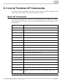
6.3 List of Terminal AT Commands . . . . . . . . . . . . . . . . . . . . . . . . . . . . . . . . . . . . .
6.4 Status Messages . . . . . . . . . . . . . . . . . . . . . . . . . . . . . . . . . . . . . . . . . . . . . . . .
6.5 LOG Files . . . . . . . . . . . . . . . . . . . . . . . . . . . . . . . . . . . . . . . . . . . . . . . . . . . . . .
6.6 Call Data Records (CDR) . . . . . . . . . . . . . . . . . . . . . . . . . . . . . . . . . . . . . . . . . .
6.7 SMS Data Records (SDR) . . . . . . . . . . . . . . . . . . . . . . . . . . . . . . . . . . . . . . . . .
6.8 Statistics - Description . . . . . . . . . . . . . . . . . . . . . . . . . . . . . . . . . . . . . . . . . . . .
94
95
96
106
115
118
119
120
7. Technical Parameters . . . . . . . . . . . . . . . . . . . . . . . . . . . . . . . 123
8. Supplementary Information . . . . . . . . . . . . . . . . . . . . . . . . . . 125
8.1 Troubleshooting . . . . . . . . . . . . . . . . . . . . . . . . . . . . . . . . . . . . . . . . . . . . . . . . .
8.2 List of Abbreviations . . . . . . . . . . . . . . . . . . . . . . . . . . . . . . . . . . . . . . . . . . . . . .
8.3 Directives, Laws and Regulations . . . . . . . . . . . . . . . . . . . . . . . . . . . . . . . . . . .
8.4 General Instructions and Cautions . . . . . . . . . . . . . . . . . . . . . . . . . . . . . . . . . . .
126
128
130
131
1. Product Overview
In this section, we introduce the 2N® BRI Lite / Enterprise product, outline its
application options and highlight the advantages following from its use.
Here is what you can find in this section:
1.1
1.2
1.3
1.4
Product Description
Safety Precautions
Upgrade
Terms and Symbols Used
2N® TELEKOMUNIKACE a.s., www.2n.cz
5
1.1 Product Description
The 2N® Enterprise / BRI Lite GSM gateway provides direct interconnection of the
ISDN with GSM networks. It can also be used for direct interconnection of an ISDN PBX
with a GSM network, ISDN telephone set and, via a terminal adapter, with an analogue
apparatus or coin machine. The voice mode, i.e. outgoing and incoming calls, is the
basic function of the gateway. Moreover, the BRI gateway provides connection to the
VoIP–SIP networks. The gateway is equipped with all functions necessary for this mode
and is very user–friendly. In addition, 2N® BRI Enterprise / BRI Lite allows you to
send and receive SMS messages. No additional devices (an external telephone, e.g.)
are required for normal operation. All gateway parameters can be set using a
configuration program (on an enclosed CD), or using the AT commands. Programmable
parameters are pre–set to make it possible to make calls as soon as the supply cable,
antenna a SIM cards are connected.
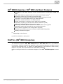
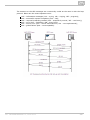
2N® BRI Enterprise / 2N® BRI Lite Differences
The 2N® BRI Enterprise and 2N® BRI Lite gateways are based on one and the same
type of hardware and apply identical firmware and control (configuration) software. The
only difference lies in the count of BRI ISDN interfaces:
Interface
BRI ISDN
2N® BRI Lite
1 (NT/TE)
2N® BRI Enterprise
2 (1 TE ; 1 NT)
Ethernet
YES*
YES*
*The VoIP–SIP support depends on Part No. (subject to licence).
Telephone Cost Cuts
Having connected 2N® BRI Enterprise / BRI Lite to your ISDN PBX, you can
make calls to the mobile network directly. This saves your PSTN – GSM
connection costs.
You do not pay for barred calls. You can set groups of barred numbers in the
gateway.
A flexible setting of the Least Cost Router helps you call GSM numbers at
minimum operational costs.
You can route calls to alternative providers' networks via the VoIP/SIP interface.
As all gateway user calls are added up for billing purposes, you are
advised to use the most advantageous tariff offered by your provider.
2N® TELEKOMUNIKACE a.s., www.2n.cz
6
2N® BRI Enterprise / 2N® BRI Lite Basic Features
Integration of the best features of two communication technologies: ISDN and
GSM
VoIP–SIP telephony support with G.711a/u and G.729ab codecs1
Intelligent routing of incoming and outgoing calls
Web interface for gateway configuration and SMS sending/receiving
Automatic no answer SMS sending for GSM networks
Automatic missed call SMS in the GSM network
Simple recording of a welcome note, DISA voice message
Automatic recording of call data and detailed statistics (CDR)
ENBLOCK/OVERLAP ISDN dialling switch option
Monitoring of ISDN BRI line statuses and alarm SMS sending option
Automatic sending of Alive SMS in user–defined intervals
Easy firmware upgrade via a configuration program
External synchronising source connection option (BRI Enterprise)
Mobility Extension2 support.
[1]
Depending on the licence
[2]
Will be available in early 2013
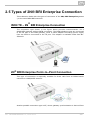
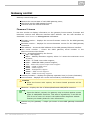
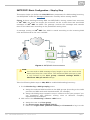
DialThru (2N® BRI Enterprise)
The difference between 2N® BRI Enterprise and 2N® BRI Lite lies in the DialThru
functionality. DialThru enables the gateway to be connected between the PBX and the
voice service provider line, i.e. PSTN. The GSM gateway in the DialThru mode routes,
based on the LCR, calls into the PSTN or GSM/UMTS networks.
Refer to the figure below for a schematic diagram of the 2N® BRI Enterprise connecti
on.
2N® TELEKOMUNIKACE a.s., www.2n.cz
7
The gateway works as a dial–through router (using both the TE and NT ports in the
DialThru
mode) for calls to a mobile network, and a monitoring system, which, with the
appropriate licence, sends SMS to the provider (in the case of line unavailability, e.g.).
The 2N® BRI Lite GSM gateway contains just one ISDN BRI port and thus cannot
work in the DialThru mode. It can be connected to a PBX on a trunk line or extension
and route calls to the GSM/UMTS networks only – see the figure below.
2N® TELEKOMUNIKACE a.s., www.2n.cz
8
1.2 Safety Precautions
It is prohibited to use any transmitters, including the GSM/UMTS gateways, in areas
where explosives are used, such as quarries.
It is prohibited to use the 2N® BRI Enterprise / BRI Lite GSM gateways at petrol
stations where mobile telephones are also prohibited.
GSM phones may affect sensitive life–saving devices in medical centres. Therefore, it is
forbidden to use GSM/UMTS devices, including the GSM gateways, in such facilities.
In general, any prohibition regarding mobile phones based on RF energy radiation
applies to GSM/UMTS devices too.
If necessary, the GSM gateways may be installed at a safe distance from the prohibited
area and connected with the original place through an Ethernet cable.
Although GSM gateways are not intended for cars or aeroplanes, all relevant
prohibitions and regulations regarding mobile phones apply to them too.
2N® TELEKOMUNIKACE a.s., www.2n.cz
9
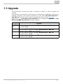
1.3 Upgrade
The manufacturer reserves the right to modify the product in order to improve its
qualities.
In response to the customers' requirements, the manufacturer constantly improves the
software contained in the product (firmware). For the latest 2N® BRI Enterprise /
2N® BRI Lite firmware version and the User Manual refer to the 2N web sites.
Refer to the S. 2, Description and Installation, for a detailed description of the 2N®
BRI Enterprise / 2N® BRI Lite firmware upgrade.
Manual
Version
Changes
1.0
The User Manual relates to the 2N® BRI Enterprise / BRI Lite firmwa
re version 1.5.0.
1.3
The User Manual relates to the 2N® BRI Enterprise / BRI Lite
firmware version 1.5.0. Text correction
1.4
The User Manual relates to the 2N® BRI Enterprise / BRI Lite
firmware version 1.14.0.
1.5
The User Manual relates to the 2N® BRI Enterprise / BRI Lite
firmware version 1.16.5.
2N® TELEKOMUNIKACE a.s., www.2n.cz
10
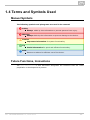
1.4 Terms and Symbols Used
Manual Symbols
The following symbols and pictograms are used in the manual:
Safety
Always abide by this information to prevent persons from injury.
Warning
Always abide by this information to prevent damage to the device.
Caution
Important information for system functionality.
Tip
Useful information for quick and efficient functionality.
Note
Routines or advice for efficient use of the device.
Future Functions, Innovations
The grey-marked text in this document designates the functions that are under
preparation or development at present.
2N® TELEKOMUNIKACE a.s., www.2n.cz
11
2. Description and Installation
This section describes the 2N® BRI Enterprise / 2N® BRI Lite product and its
installation.
Here is what you can find in this section:
2.1
2.2
2.3
2.4
2.5
Before You Start
Brief Installation Guide
Available ISDN BRI Extension Configurations
IP Voice Transmission
Types of 2N® BRI Enterprise Connection
2N® TELEKOMUNIKACE a.s., www.2n.cz
12
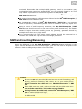
2.1 Before You Start
Caution
Make sure that you are equipped with all system components
necessary for putting 2N® BRI Enterprise / Lite in operation (SIM
card, ISDN phone and/or duly configured ISDN BRI line of your PBX or
PSTN, an available Ethernet/USB socket and a PC for initial gateway
configuration).
Product Completeness Check
Before installing this product, check whether the 2N® BRI gateway delivery complies
with the following packing list:
Package
BRI Lite
BRI Enterprise
2N® BRI Enterprise / Lite
1
1
Power supply adapter
1
1
Long antenna
1 – 2*
1 – 2*
Ethernet cable
1
1
BRI ISDN cable
1
2
Wall mounting set
1
1
*depends on the Part No.
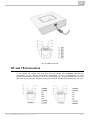
Connector Lay–Out – Lower Side
The following connectors are available on the BRI gateway bottom:
Connector type
DC Jack 2.1mm supply connector
BRI Lite
YES
YES
10/100BaseT Ethernet connector
YES
YES
ISDN BRI TE interface
NO
YES
ISDN BRI NT interface
NO
YES
ISDN BRI NT/TE interface
YES
NO
2N® TELEKOMUNIKACE a.s., www.2n.cz
BRI Enterprise
13
Caution
2N® BRI Lite has two RJ45 connectors, which, however, are
cross–connected into one ISDN BRI. Be sure to connect just one ISDN
BRI line to make the system work properly. Which of the RJ45
connectors will be used depends on the type of the equipment to be
connected (NT/TE) and the interconnecting cable (cross/straight).
Connector Lay–Out – Upper Side
There are SMA female antenna connectors to each GSM/UMTS module on the 2N® BRI
Enterprise / Lite upper side.
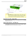
Status LED Indicators – 2N® BRI Lite
The 2N® BRI Lite status is indicated by five LEDs on the front side. BRI 1 and BRI 2
indicate the status of ISDN BRI B–channels and CH 1 and CH 2 indicate the status of
each GSM/UMTS module. Refer to the table below for the statuses
2N® TELEKOMUNIKACE a.s., www.2n.cz
14
LED Indicators
Power
supply
green light – mains powered
no light – device switched off
GSM/UMTS
network
green light – call in progress
red light – error
green flashing – network registration, SMS
red flashing – module restart
Red/green flashing – signal intensity indication
ISDN port
green light – 2 calls in progress
green flashing – ISDN synchronisation/active call
red light – ISDN disconnected
red flashing – synchronisation of lower ISDN layers
Ethernet
port
green light + no orange light – disconnected
green light + orange flashing – 100BaseT connected, in
operation
no green light + orange light – 10baseT connected, no operation
green flashing + orange flashing – 10BaseT connection, in
operation
Signal
intensity
Signal intensity indication:one segment = less than –109dbmtwo
segments = more than –95dbmthree segments = more than
–81dbmfour segments = more than –65dbm
*If the devices have been interconnected, the layers will not be connected until the
first call.
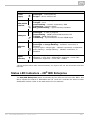
Status LED Indicators – 2N® BRI Enterprise
The 2N® BRI Enterprise status is indicated by five LEDs on the front side. BRI 1 and
BRI 2 indicate the status of ISDN BRIs and CH 1 and CH 2 indicate the status of each
GSM/UMTS module. Refer to the table below for the statuses.
2N® TELEKOMUNIKACE a.s., www.2n.cz
15
LED Indicators
Power
supply
green light – mains powered
no light – device switched off
GSM/UMTS
network
green light – call in progress
red light – error
green flashing – network registration, SMS
red flashing – module restart
Red/green flashing – signal intensity indication
ISDN port
green light – 2 calls in progress
green flashing – ISDN synchronisation/active call
red light – ISDN disconnected
red flashing – synchronisation of lower ISDN layers
Ethernet
port
green light + no orange light – disconnected
green light + orange flashing – 100BaseT connected, in
operation
no green light + orange light – 10baseT connected, no operation
green flashing + orange flashing – 10BaseT connection, in
operation
Signal
intensity
Signal intensity indication:one segment = less than –109dbmtwo
segments = more than –95dbmthree segments = more than
–81dbmfour segments = more than –65dbm
* If the devices have been interconnected, the layers will not be connected until the
first call.
**Remember to set the signal intensity indication in the gateway configuration menu.
Potential GSM/UMTS Troubles
All 2N® GSM gateways work reliably under a long–time full load. The following
problems may be caused by GSM/UMTS networks:
The GSM/UMTS module(s) cannot log in, log in slowly, or log out occasionally.
This problem may be caused by any of the following situations:
The GSM/UMTS signal is low. The minimum signal level should be
approximately –80dBm. If lower, change the antenna position or type!
The GSM/UMTS cell (BTS) to which the GSM/UMTS modules are trying to
log in is overloaded. Change the antenna position or reduce the count of
the logged–in GSM/UMTS modules.
One of the GSM/UMTS modules is permanently logged–out or fails to make
outgoing calls:
The problem indicates a GSM/UMTS network overload on the installation
site. To eliminate the problem, set the Relax delay parameter to 2
seconds. If the GSM module fails to log in or rejects to make outgoing
2N® TELEKOMUNIKACE a.s., www.2n.cz
16
GSM calls even after the gateway restart, consult your GSM provider for
your SIM card/GSM module availability.
The manufacturer shall not be held liable for any SIM card or provider service
unavailability in the case of a breach of the provider's SIM terms and conditions for the
SIM card use.
2N® TELEKOMUNIKACE a.s., www.2n.cz
17
2.2 Brief Installation Guide
Installation Conditions
The following installation conditions have to be met for a proper installation:
2N® BRI Enterprise / BRI Lite is to be installed on a site with enough free
space.
2N® BRI Enterprise / BRI Lite is to be mounted on a suitable vertical surface.
For this purpose, a hanger is included in the gateway delivery, which is fitted to
the wall using dowels and screws and used for gateway hanging.
It is possible to operate the gateway in another working position too, e.g. on a
desk, for a short time for servicing and testing purposes, for example.
Any excess of the allowed working temperature may not affect the 2N® BRI
Enterprise / BRI Lite function immediately but may result in faster ageing and
lower reliability. For the allowed working temperature and humidity ranges refer
to S. 7.
2N ® BRI Enterprise / BRI Lite is not designed for high–vibration
environments such as means of transport, machine rooms, and similar.
2N® BRI Enterprise / BRI Lite is not designed for dusty environments or
places exposed to high humidity and temperature changes.
2N® BRI Enterprise / BRI Lite may not be exposed to aggressive gases, acid
and solvent vapours (during cover cleaning, e.g.).
2N® BRI Enterprise / BRI Lite is intended for indoor use. It may not be
exposed to rain, flowing water, condensing moisture, fog, and so on.
2N® BRI Enterprise / BRI Lite may never be exposed to direct sunshine or
placed close to heat sources (radiators).
A sufficient clearance must be kept over and under 2N® BRI Enterprise / BRI
Lite for cabling and air flow to carry off the heat.
A sufficient GSM/UMTS signal intensity has to be provided for 2N® BRI
Enterprise / BRI Lite.
An adequate capacity of the GSM/UMTS network has to be ensured (no BTS
2N® TELEKOMUNIKACE a.s., www.2n.cz
18
overload). Remember that multiple GSM gateways used in one location may
overload the base transceiver station (BTS) you are currently logged in to. This
may lead to a permanent or occasional rejection of GSM/UMTS calls!
No strong electromagnetic radiation is allowed on the 2N® BRI Enterprise /
BRI Lite installation site.
No strong electromagnetic reflections are allowed on the 2N® BRI Enterprise /
BRI Lite antenna installation site.
An inappropriate location of 2N® BRI Enterprise / BRI Lite or its antenna
close to television, broadcasting and/or other rf–sensitive sets may impair the
function of these sets.
Being a source of radio frequency emissions, the 2N® BRI Enterprise / BRI
Lite antenna should not occur in the close vicinity of the human body. The health
hazard is higher than with mobile phones as, generally, gateways shared by
multiple users show a very high traffic.
It is recommended that the power supply adapter should be connected to a
network with a UPS back–up and due overvoltage protection.
SIM Card Inserting/Removing
Insert the SIM card in the 2N® BRI Enterprise / BRI Lite bottom as shown in the
figure. As the SIM slots are of the Push/Pull type, just slide the card in and push it into
position. Push the SIM gently to slide it out of the slot.
Caution
Be sure to set such provider/SIM card services as call forwarding, call
barring, preferred networks, SMS centre, etc. in your mobile phone
before inserting the SIM card into 2N® BRI Enterprise / BRI
Lite.
If two SIM cards are used, make sure that both the SIM cards have
one and the same PIN or PIN code request disable.
Having inserted the SIM card, restart 2N® BRI Enterprise / BRI
Lite to make the SIM card log in.
Remember to disable the Another call on line service before using
the SIM cards!
2N® TELEKOMUNIKACE a.s., www.2n.cz
19
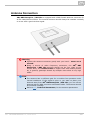
Antenna Connection
2N® BRI Enterprise / BRI Lite is equipped with a SMA female antenna connector for
all the GSM/UMTS modules. The external antenna should always be installed vertically
on a site with a good wireless signal.
Warning
Tighten the antenna connector gently with your hand – never use a
wrench!
Being a source of radio frequency emissions, the 2N® BRI
Enterprise / BRI Lite antenna should not be very close to the
human body. The health hazard is higher than with mobile phones
as, in general, gateways shared by multiple users show a very high
traffic.
Note
The antenna has a sufficient gain for a trouble–free operation under
normal conditions. If the signal is poor or you want to place your
antenna away from 2N® BRI Enterprise / BRI Lite, you can use an
antenna with an SMA–connector terminated cable. The antenna should
be mounted vertically.
Refer to S.7, Technical Parameters, for the antenna parameters.
2N® TELEKOMUNIKACE a.s., www.2n.cz
20
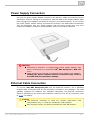
Power Supply Connection
Use only the power supply adapter included in the delivery. Make sure that the electric
distribution network voltage is in compliance with the data on the supply adapter plate
before plugging the adapter and that the antenna is connected properly. If you connect
the power supply without having connected the antenna, the GSM module transmitter
may get damaged. Plug the supply adapter into the mains socket and only then
connect the adapter connector to the gateway. Refer to the status indicators.
Warning
Connecting a defective or inappropriate power supply adapter may
lead to a temporary or permanent 2N® BRI Enterprise / BRI Lite
error!
Check whether the antenna is connected before plugging the adapter.
Feeding the device without antenna connection may result in
the GSM module transmitter damage.
Ethernet Cable Connection
To connect 2N® BRI Enterprise/Lite into the Ethernet network, use a standard
straight cable terminated with RJ–45 connectors (included in the package). The GSM
gateway supports the 10BaseT and 100BaseT standards, the Ethernet connection
status is indicated by the status LED indicators located on the RJ–45 connector (refer
to S. 2.1 for details).
Caution
The Ethernet interface is used for remote supervision
configuration only, i.e. does not contain the VoIP interface.
With a proper licence, the device provides the VoIP–SIP support.
2N® TELEKOMUNIKACE a.s., www.2n.cz
and
21
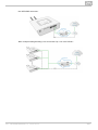
RJ–45 LAN Connector
NT and TE Connectors
1 not used2 not used3 Tx4 Rx5 Rx6 Tx7 not used8 not usedISDN devices are
connected to the NT/TE connectors depending on the configuration of your
telecommunications equipment. They are connected via a 4–wire passive bus with the
aid of RJ–45 connectors. Refer to the figure below for the NT/TE connector pin lay–out.
2N® TELEKOMUNIKACE a.s., www.2n.cz
22
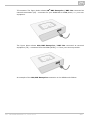
TE connector The figure below shows 2N® BRI Enterprise / BRI Lite connected as
network termination (NT) – extension for your ISDN PBX or ISDN phone, i.e. your own
equipment.
The figure below shows 2N® BRI Enterprise / BRI Lite connected as terminal
equipment (TE) – extension from the ISDN (PSTN), i.e. from your service provider.
An example of the 2N® BRI Enterprise connection in the ISDN mode follows.
2N® TELEKOMUNIKACE a.s., www.2n.cz
23
Caution
2N® BRI Lite is equipped with just one ISDN BRI. Hence, two
independent devices cannot be connected at the same time!
2N® TELEKOMUNIKACE a.s., www.2n.cz
24
2.3 Available ISDN BRI Extension
Configurations
You have to know the way of connection of your ISDN devices in order to configure
your 2N® BRI Enterprise / BRI Lite GSM gateway correctly. For information on your
ISDN type, check your ISDN extension provider's registration form or contact your
telephone network administrator.
Point–to–Point Configuration
The Point–to–Point (EuroISDN with DDI) configuration interconnects directly one ISDN
terminal (TE) and a network terminal (NT) (see the figure below). This type is applied
mainly where PBXs are connected to the ISDN.
Point–to–Multipoint Configuration
Point–to–Multipoint (EuroISDN with MSN) is another type of ISDN terminal
interconnection. Here the network terminal (NT) is interconnected with up to eight
ISDN terminals through a 4–wire passive bus as shown in the figure below.
2N® TELEKOMUNIKACE a.s., www.2n.cz
25
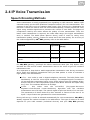
2.4 IP Voice Transmission
Speech Encoding Methods
Voice transmission is strictly separated from signalling in VoIP networks. Modern VoIP
networks mostly use the RTP (Realtime Transport Protocol) for voice transmission. The
purpose of the RTP is only to transmit data (voice) from a source to a destination at
real time. Codecs are used to save the channel data capacity. Codecs process the voice
signal using variable algorithms to minimise the volume of user data. The degree of
compression used by the codec affects the quality of voice transmission. Thus, the
better voice transmission is required, the wider data range (the higher transmission
rate) is needed. The MOS (Mean Opinion Score) scale is used for rating voice
transmission quality, where 1 means the worst and 5 the best quality. For a survey of
the codecs supported by 2N® BRI gateway refer to the table below.
Codecs supported
Standard
Algorithm
Transmission rate
[kbps]
MOS
G.711a
PCM
64
4.1
G.711u
PCM
64
4.1
G.729 G.729 is an optional part of the
system.
CS–ACELP
8
3.92
For 2N® BRI gateway, quadruple the above mentioned rates (two fully duplex calls)
and add the TCP and IP header transmission rate to the result to get the resultant
transmission rate.
It is important to keep both a stable appropriate transmission rate during connection
and a small and identical transmission time per data packet in order to maintain a
high–quality voice transmission.
G.711 – this codec is used in digital telephone networks. The PCM (Pulse Code
Modulation) is used for voice signal encoding. The sampled signal is encoded in
12 bits and then compressed using a non–linear scheme into the resultant 8 bits.
Europe uses the A–law compression system while North America and Japan obey
the µ–law. The resultant data flow is 64 kbps.
G.729
–
this
codec
uses
the
CS–ACELP
(Conjugate–Structure
Algebraic–Code–Excited Linear–Prediction) algorithm with the resultant
transmission rate of 8 kbps. The speech signal is split into blocks of 10 ms each.
The parameters of these blocks are then inserted in frames of the size of 10
bytes. 2–byte frames are generated for noise transmission.
During call set–up, a codec is selected automatically for voice transmission. 2N® BRI g
ateway supports the codecs included in the table above. The type of codec to be used
depends on your VoIP network (individual devices) and your 2N® BRI gateway
2N® TELEKOMUNIKACE a.s., www.2n.cz
26
configuration.2N® BRI gateway is designed primarily for VoIP corporate networks and
tries to meet the opponent's codec requirements. If a codec is requested that is
incompatible with 2N® BRI Enterprise, the call will be rejected.
The SIP and ITU–T H.323 recommended protocols are mostly used for connection
establishing, maintaining and cancelling. 2N® BRI gateway uses the SIP (Session
Initiation Protocol) signalling.
Tip
In the case of separated direct connection of your SIP Proxy and 2N®
VoiceBlue Next, use the G.711 codec to achieve a high voice
quality.
SIP Components
The following components are involved in the SIP message exchange:
UAC (User Agent Client) – the terminal device client, which initiates SIP
signalling.
UAS (User Agent Server) – the terminal device server, which responds to SIP
signalling from the UAC.
UA (User Agent) – a SIP network terminal (SIP phones, gateways to other
networks, etc.), which contains the UAC and UAS.
Proxy server – receives connection requests from the UA and transfers them to
the next Proxy server if the given station is not under it administration.
Redirect server – receives connection requests, but, instead of sending them to
the called line, sends them back to the requesting device asking for where to
route the request.
Location server – receives registration requests from the UA and updates the
terminal database accordingly.
All the server components (Proxy, Redirect, Location) are mostly on one physical
device called Proxy server, which is responsible for keeping a client database and
connection establishing, maintaining and terminating, as well as call routing.
The 2N® BRI gateway VoIP–GSM gateway acts as a UA in any case (has the same
functions as a VoIP phone), i.e. receives call set–up requirements and, on the basis of
its inner LCR table, routes calls to GSM networks.
None of the SIP–defined server components are integrated in the 2N® BRI gateway
gateway.
SIP Signalling Messages
Below is a list of messages sent via the SIP:
INVITE – connection set–up request;
ACK – INVITE confirmation by the final message addressee;
BYE – connection termination;
CANCEL – failed connection cancellation;
REGISTER – UA registration with the SIP Proxy;
OPTIONS – server capability query.
2N® TELEKOMUNIKACE a.s., www.2n.cz
27
The answers to the SIP messages are numerically coded as the case is with the http
protocol. Below are the most important ones:
1XX
2XX
3XX
4XX
5XX
6XX
–
–
–
–
–
–
information messages (100 – trying, 180 – ringing, 183 – progress);
successful request completion (200 – OK);
request forwarding needed (302 – temporarily moved, 305 – use Proxy);
error (403 – forbidden, 486 – busy here);
server error (500 – Server Internal Error, 501 – not implemented);
global failure (606 – not acceptable).
2N® TELEKOMUNIKACE a.s., www.2n.cz
28
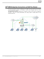
2.5 Types of 2N® BRI Enterprise Connection
This subsection deals with the types of connection of the 2N® BRI Enterprise gatewa
y to the main ISDN BRI extension.
ISDN TE – 2N® BRI Enterprise Connection
The connection type shown in the figure below provides communication via a
GSM/UMTS gateway without PSTN connection. The ISDN telephone sets are connected
to the NT port of the GSM gateway, while a mains adapter simulating power supply
from the PSTN is connected to the TE port. The adapter is available under Part No.
5020002.
2N® BRI Enterprise Point–to–Point Connection
This type of connection is especially suitable for direct calls from an ISDN branch
network to a GSM/UMTS network.
Another possible connection type is NT, where gateway synchronisation is derived from
2N® TELEKOMUNIKACE a.s., www.2n.cz
29
the PSTN BRI extension.
With multiple GSM gateways, the connection lay–out is as follows:
2N® TELEKOMUNIKACE a.s., www.2n.cz
30
2N® BRI Enterprise Connection as DialThru Router
This type of connection saves one BRI port to the PBX. Incoming PSTN calls are treated
by the GSM/UMTS gateway in the DialThru mode while outgoing calls are routed
according to the LCR table.
The figure below shows the gateway as a DialThru router for the Point–to–Multipoint
extension. Calls are routed automatically into GSM, UMTS or ISDN based on the
internal LCR rules.
2N® TELEKOMUNIKACE a.s., www.2n.cz
31
3. Making Calls via BRI
Gateway
This section describes the call routing techniques via an ISDN BRI GSM gateway. The
purpose of the settings is to improve your call efficiency and cut your call costs.
Here is what you can find in this section:
3.1 Supported 2N BRI Gateway Functions
3.2 Call Routing Principles
2N® TELEKOMUNIKACE a.s., www.2n.cz
32
3.1 Supported 2N BRI Gateway Functions
Time/destination based call routing
B–channel based call routing
Intelligent incoming CLIP routing (based on Calling Line Identification
Presentation)
Auto CLIP routing (automatic incoming call routing to a line stored in the
AutoCLIP table)
Time LCR (Least Cost Router) based outgoing call routing
DISA (tone dialling)
DISA into GSM (tone DID from ISDN ports to GSM networks)
CallBacks to GSM
SMS sending/receiving
SMS at no answer
Configuration via web interface
Access password for configuration on all ports
CLIP and CLIR for incoming GSM calls
ENBLOCK/OVERLAP dialling transmission to ISDN
Generation/retransmission from GSM of AoC pulses
Table of allowed/barred numbers calling from GSM
ISDN BRI monitoring with Alert SMS option
Alive SMS in user defined intervals
2N® Mobility Extension feature
2N® TELEKOMUNIKACE a.s., www.2n.cz
33
3.2 Call Routing Principles
2N® BRI Lite
The gateway is equipped with one BRI ISDN and one VoIP–SIP ports. You can select
one of the following incoming call processing modes for each of the ports via the web
interface:
Use LCR table – in this case, calls with be routed as set in the LCR table;
Reject calls – all incoming calls will be rejected;
Route to port – all calls will be routed to the selected port without change.
If your BRI gateway is connected to a PBX subscriber line, you can activate DTMF. If
you do so, the GSM gateway automatically answers any incoming call from BRI ISDN
and offers the caller dialtone for another DTMF dialling. The call will then be routed to
the GSM/UMTS modules.
Incoming GSM/UMTS calls can be either DTMF–processed or automatically routed to
the ISDN BRI / VoIP–SIP interface according to the active intelligent GSM gateway
rules functions (Auto CLIP, CLIP routing). They are routed to the ISDN NT or ISDN TE
interface depending on the GSM gateway configuration.
Incoming GSM/UMTS calls can also be rejected and, with the aid of CLIP, used for
CallBack.
The LCR algorithm routes outgoing calls on the basis of the call type, current time
tariff, day in a week and, if available, free minutes of GSM providers.
2N® BRI Enterprise
The gateway is equipped with two BRI ISDN and one VoIP–SIP ports. You can select
one of the following incoming call processing modes for each of the ISDN ports via the
web interface
Use LCR table – in this case, calls with be routed as set in the LCR table;
Reject calls – all incoming calls will be rejected;
Route to port – all calls will be routed to the selected port without change.
If your BRI gateway is connected to a PBX subscriber line, you can activate DTMF. If
you do so, the GSM gateway automatically answers any incoming call from BRI ISDN
and offers the caller dialtone for another DTMF dialling. The call will then be routed to
the GSM/UMTS modules.
Incoming GSM/UMTS calls can be either DTMF–processed or automatically routed to
the ISDN BRI interface according to the active intelligent GSM gateway rules functions
(Auto CLIP, CLIP routing). They are routed to the ISDN NT, or ISDN TE interface
depending on the GSM gateway configuration.
Incoming GSM/UMTS calls can also be rejected and, with the aid of CLIP, used for
CallBack.
The LCR algorithm routes outgoing calls on the basis of the call type, current time
tariff, day in a week and, if necessary, free minutes of GSM providers.
2N® TELEKOMUNIKACE a.s., www.2n.cz
34
Tip
2N® BRI Enterprise / BRI Lite can also route outgoing calls into
the GSM/UMTS networks according to the B–channel used. In that
case, the GSM/UMTS module is paired with a specific B–channel of the
ISDN BRI line.
LCR Table
The LCR (Least Cost Routing) table is the key telephone cost cutting factor. It helps
you set call routing rules according to the CLIP, daytime and day in a week. By
entering state (bank) holidays into the LCR table you achieve even more remarkable
cuts.
To make the prefix–based call routing to external ports and the LCR table work
properly, select the module for the call in the Outgoing destination parameter while
creating the LCR record.
The gateway also allows you to route outgoing GSM calls on the basis of the SIM card
position. Such outgoing calls are not routed according to the GSM provider's number
but through the defined GSM module.
In addition, the ISDN ports can work in the DialThru mode. This means that all calls
are routed to the respective port without any check. Namely, from TE to NT and vice
versa.
Outgoing GSM Call Routing from Internal ISDN
If the GSM/UMTS gateway is connected to a subscriber line of your PBX, you are
advised to enable the DISA function to GSM to make your GSM gateway answer every
call routed to it by the PBX and wait for further dialling to GSM networks.
The GSM/UMTS gateway routes outgoing calls to GSM as follows:
The calling subscriber dials a user number.
If the user dialling is evaluated as Access to GSM gateway, the gateway barred
number table is searched through and, if a match is found, the call setup request
is rejected.
With an outgoing call, the gateway waits for further digits to be dialled. This
timeout results in a certain delay between the subscriber's dialling and the
subsequent dialling by the GSM gateway. Therefore, select the Count of dialled
digits for the called destinations while configuring your gateway. Then, the
gateway initiates the outgoing call processing algorithm on receiving the last digit
The dialling prefix is first checked against the prefixes included in the first row of
the LCR table. If no match is found, the following row is used for check and so
on.
In case the prefix and call time comply with the routing rules, the call is routed
according to the first LCR rule to the module corresponding to the particular
Outgoing GSM group included in the Outgoing destinations list.
If the selected GSM module is busy or has a low credit, the preceding step is
repeated and the next LCR row is checked.
In case the selected GSM module is free and has a sufficiently high credit, the
GSM gateway starts dialling the GSM number.
If the calling subscriber number has an unknown prefix or all routes are busy, the
2N® TELEKOMUNIKACE a.s., www.2n.cz
35
GSM gateway rejects the call setup request.
An outgoing call is not billed until the called party answers the call.
The GSM network signals the off–hook and the GSM gateway transfers this
information to the PBX.
The gateway is able to generate the AoC tariff pulses during an outgoing call,
which, if the GSM gateway is connected to the PBX, allows for call cost logging
per user.
Incoming GSM Call Routing
Incoming GSM calls are routed by the algorithm described in the following steps and
shown in the figure below:
Incoming calls are processed according to the Mode parameter in the Incoming GSM
calls table. The following options are available:
Reject/Ignore incoming calls – incoming calls are not routed to extensions.
The call setup request can either be rejected or ignored on the GSM side (the
calling party hears the check ringing tone).
Report to PC – information on an incoming call is sent to a PC equipped with the
management software. The calling subscriber gets a voice message or the check
ringing tone. The management software then completes the call routing
procedure.
CallBack – this function helps establish connection on the account of the SIM
card inserted in the gateway. The incoming call is either ignored or rejected.
After the calling subscriber hangs up, the GSM gateway sets up connection to the
defined extension. When the extension answers, the GSM gateway replays the
CallBack message to the extension while establishing connection to the
previously calling GSM/UMTS subscriber. After the CallBack message, the GSM
gateway interconnects the call. If CallBack with incoming call ignoring is enabled
and the calling party fails to hang up within a defined timeout (default=10s), the
CallBack function is disabled for this call and the subscriber can go on dialling the
extension number. Set the CallBack function in the CLIP routing table.
If none of the above mentioned options is selected, the AutoCLIP routing table is
checked. If the calling number is found, the call is routed to the extension whose
number is assigned to the calling number in the table.
In case the calling number is not included in the AutoCLIP routing table, or the
AutoCLIP routing function is disabled, the gateway receives the incoming call and
either replays a voice message or transmits the dialtone to the calling subscriber.
Then the gateway awaits the count of digits necessary for call setup. Define the
minimum and maximum counts of DTMF digits in the Incoming GSM calls
menu.
If the gateway does not receive the minimum count of digits and no other digit
comes from the GSM network within the timeout defined in the DTMF dialling
delay, the call is rerouted to the extension included in the List of extensions.
If call forwarding to extension is inactive, the incoming call is rejected.
2N® TELEKOMUNIKACE a.s., www.2n.cz
36
DISA Message
With DISA activated and DISA welcome note recorded, the message is played to every
incoming call whose CLIP is not included in the AutoCLIP table. After playing, the
gateway waits for the first DTMF digit for the time period defined in the Incoming GSM
calls – DTMF dial timeout table. Having received the count of digits defined in the Inco
ming GSM calls – Minimum DTMF digits parameter, the gateway activates connection to
the SIP proxy or telephone via the port included in the ISDN parameters table with the
DTMF–received number. You can upload the DISA message using the GSM gateway
web interface.
Or, you can record the message using your PC as disa.wav and load it into the gateway
using the configuration program via the web interface.
DISA Recording via PC and Web Interface
The DISA voice message parameters for PC recording are as listed below: maximum
duration of 65s, compression according to ISDN A–law, mono, sampling frequency of
8kHz. Name the file Disa.wav and load it via the Gateway control – Voice messages we
b interface into the gateway.
DISA voice message parameters
Sound format:
WAV
Sampling frequency:
8 kHz
Channels:
1 mono
Codec:
ISDN A–law
2N® TELEKOMUNIKACE a.s., www.2n.cz
37
4. First Launch
Having completed the physical installation, get acquainted with the factory settings and
operation of the 2N® BRI Enterprise / BRI Lite gateway.
Here is what you can find in this section:
4.1
4.2
4.3
4.4
4.5
Ethernet Interface
Licence
Firmware Version
Factory Reset
Basic Configuration – Step by Step
2N® TELEKOMUNIKACE a.s., www.2n.cz
38
4.1 Ethernet Interface
The BRI gateway can be fully configured via the web interface at
http://IP_gateway_address. Make sure that a device equipped with a web browser (PC,
NB, Tablet, etc.) has been connected for successful connection to the BRI gateway
configuration interface. The device also supports configuration via an extended AT
command set on the Telnet interface (IP port 23).
Tip
The device also supports configuration via an extended AT command
set on the Telnet interface (IP port 23). Refer to Subs. 6, page for
details.
The BRI gateway supports DHCP (client). By default, the DHCP support is disabled.
Tip
If DHCP is active, use specialised detection software (for LANs only) to
identify the assigned IP address. Refer to the www.2n.cz web sites,
BRI Gateways (IP Scanner) for the software.
Use the web configuration interface in the Gateway configuration – Ethernet
configuration section to set the Ethernet interface.
Ethernet Interface Factory Settings
IPv4 address
192.168.1.2
IP mask
255.255.255.0
Gateway
192.168.1.1
User name
Admin
User password
2n
Caution
Change the user name and password during your first gateway
configuration to avoid unauthorised access to your gateway
configuration! Refer to page for details!
2N® TELEKOMUNIKACE a.s., www.2n.cz
39
Tip
In the event of data loss or configuration interface unavailability,
perform the factory reset to retrieve the data. Doing so, however, you
reset all the default values in your gateway. Refer to Subs. 4.4, p. for
details.
MAC Address
The BRI gateway has a unique, factory–set MAC (Media Access Control) address. Refer
to the rear side label of your device or the gateway web interface for the MAC address.
The MAC address can be user–changed.
Tip
If you use DHCP, you are advised to set permanent assignment of one
and the same IPv4 address to the defined MAC address to avoid
unexpected change of the gateway IPv4 address and subsequent
VoIP–SIP setting errors.
2N® TELEKOMUNIKACE a.s., www.2n.cz
40
4.2 Licence
The BRI gateway can contain different licence keys depending on the Part No. Refer to
the Gateway control – Firmware/Licence section via the web interface for the current
licence key status.
Use this section to download a new licence key into your gateway in order to change
the current software licence status.
Caution
The 2N® BRI Enterprise / BRI Lite gateway can contain
time–limited software licences (for SIP signalling, Mobility Extension,
etc.). Such licences are limited to a certain period of time (hours)
during which the gateway provides its services. Every GSM gateway
restart adds one hour to the internal licence counter value!
A 2N® BRI gateway with an expired licence processes no incoming or
outgoing calls! Ask your dealer for licence term prolongation or an
unlimited licence in due time.
Restricted Use in GSM / UMTS Networks
Some types of BRI gateways may be locked for use in specified GSM/UMTS networks
only. This means that you will not be able to use such gateways in networks other than
the recommended GSM/UMTS networks. This state is signalled by a red LED in the
given GSM/UMTS module and a 'netw–err' cause in the diagnostics. Contact your
dealer please for more information.
Tip
Contact your dealer please for more information.
2N® TELEKOMUNIKACE a.s., www.2n.cz
41
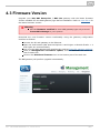
4.3 Firmware Version
Upgrade your 2N® BRI Enterprise / BRI Lite gateway with the latest firmware
version available for this GSM gateway type before installation. Refer to www.2N.cz for
the latest firmware version.
Warning
Use the firmware certified for this GSM gateway type only to avoid
irreversible damage to your system!
Download the new firmware version comfortably using the gateway configuration
interface as follows:
Connect the PC and gateway to the Ethernet.
Open the web browser (MS Internet Explorer 9 and higher or Mozzila Firefox v. 4
and higher are recommended).
Log in to the GSM gateway web interface by entering http://IP_gateway_address
Click on Management–>Firmware update, then on Browse and select the
new firmware file.
Click on the Download firmware icon in the bottom part of the web site.
The BRI gateway will perform upgrade automatically.
2N® TELEKOMUNIKACE a.s., www.2n.cz
42
4.4 Factory Reset
Should you forget your password or set the IP interface incorrectly, you can reset the
factory values. Press the Reset button right to the BRI ISDN connector for a rather
long time to reset the default values.
Doing so, you reset all the factory configuration values for all the parameters including
those related to the Ethernet interface and access data.
Caution
By resetting the default configuration values, you change the Ethernet
interface settings and have to reconfigure the gateway subsequently.
Note
Press the Reset button for a short time (0.5 s) to restart the GSM
gateway.
2N® TELEKOMUNIKACE a.s., www.2n.cz
43
4.5 Basic Configuration – Step by Step
This subsection helps you put your BRI gateway in operation for the first time. Refer to
the paragraphs of S. 3 for more detailed settings.
Install the GSM gateway as instructed in Subs. 2.2. Remove the SIM cards or
insert the PIN–disabled SIM cards before the first launch.
Connect the GSM gateway to the Ethernet to be able to get connected to the
address mentioned in Subs. 4.1, page from the web interface. If the default IP
address of your gateway is not suitable for your Ethernet installation, change the
IP address setting as follows:
Disconnect the configuration terminal from the Ethernet.
Disconnect the GSM gateway from the Ethernet.
Get an Ethernet switch or an Ethernet crossed cable.
With the crossed cable, interconnect the configuration terminal directly with
the GSM gateway.
With the Ethernet switch, connect the configuration terminal and GSM
gateway to the switch. We do not recommend you to connect any other
device.
Change the IPv4 setting in your configuration terminal Ethernet settings to,
e.g.: IP=192.168.1.200, Net mask: 255.255.255.0
Open your web browser and enter the IP address of your GSM gateway.
Complete the factory login data.
Change the required settings in the Gateway configuration – Ethernet
configuration section and save the changes into the GSM gateway.
Connect the GSM gateway to a standard Ethernet.
Rechange the IP settings of the configuration terminal and reconnect the
terminal to a standard Ethernet.
Enter the new IP address of your GSM gateway to get connected to the web
interface.
Set the current time and date for the GSM gateway in the Gateway control –
Date/Time menu.
Check the Licence status for 'unlocked' in the Gateway control –
Firmware/Licence menu. If the status is not unlocked, your GSM gateway is not
equipped with the proper licence (refer to Subs 4.2). Contact your dealer for the
licence key.
Set the correct PIN code value in the Gateway configuration – System
parameters menu to meet the PIN code of the SIM cards used.
Set new login data in the Gateway configuration – Login configuration menu.
Switch off the GSM gateway and insert the SIM cards. Connect the antenna to
the GSM gateway and switch the gateway on.
The GSM gateway factory configuration allows you to make outgoing calls without
any additional programming. All you have to do is set the correct values for the
BRI ISDN and VoIP interfaces.
Should you have problems with the gateway functions, follows the instructions below
please:
Read the User Manual carefully and check all the parameters.
Find answers to your questions at http://faq.2n.cz (Frequently Asked Questions).
Contact your servicing centre.
2N® TELEKOMUNIKACE a.s., www.2n.cz
44
It is recommended that you should attend certified training courses at 2N to be able to
install the whole system successfully.
2N® TELEKOMUNIKACE a.s., www.2n.cz
45
5. Introduction to
Configuration Interface
This section introduces the configuration interface of the 2N® BRI Enterprise / BRI
Lite product.
Here is what you can find in this section:
5.1 Configuration Web Interface
Gateway control
Gateway Configuration
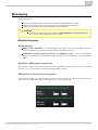
Messaging
SMTP/POP3 Basic Configuration – Step by Step
SMPP Basic Configuration – Step by Step
Monitoring
List of SNMP traps
Others
2N® TELEKOMUNIKACE a.s., www.2n.cz
46
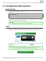
5.1 Configuration Web Interface
Essential Data
The 2N® BRI Enterprise / BRI Lite web interface supports the following web
browsers:
MS Internet Explorer v9
Mozilla Firefox v4 and higher
Any other web browsers may cause troubles. The recommended screen resolution is
1280x1024 and colour quality 32bit and higher. The configuration interface is available
in the English language version only at present.
Tip
Use the F11 key to display the full–screen mode.
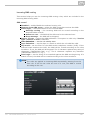
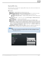
Login
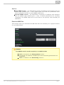
Enter the server IP address into your web browser to log in to the web configuration
interface of your BRI gateway. The following login dialogue will get displayed.
Just one user may be logged in at one time. Refer to Subs. 4.1, page for access data
default values.
Tip
The one–user limitation applies to the web interface access only. If
Telnet is used, ten users may be logged in at the same time.
2N® TELEKOMUNIKACE a.s., www.2n.cz
47
A five–minute4 time limit is defined for login, which is renewed automatically when the
user keeps active on the web interface. When this time interval expires, the user is
logged out automatically. Click on Refresh to restore the maximum time limit.
Caution
You are recommended to change these default login data upon the
first login to increase security of your system significantly.
Web Icons
Caution
Remember to press the Save settings button to save the changes in
order to avoid loss of new data after leaving the current configuration
window!
[4]
Set the time limit value in the Gateway – Web configuration – Auto logout section.
2N® TELEKOMUNIKACE a.s., www.2n.cz
48
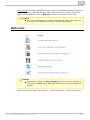
Home Page
Upon login, you get onto the home page (see the figure below) of the Gateway section.
There is a menu to the left, divided into the Gateway control and Gateway
configuration items. You can see the current login time counter status and the
Refresh button for time limit refreshing in the right–hand upper corner.
The Logout button on the home page is used for user logout. You will be notified of
every successful logout to avoid reuse of your login data.
The following sections are located in the upper menu too:
SIM client – for connection to the 2N® SIM Star system.
SMS – for receiving/sending SMS via the web interface.
Messaging – for receiving/sending SMS via SMPP or SMTP/POP3
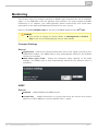
Monitoring – for gateway monitoring via SNMP
Utils – including extending system tools (Network capture, Report capture).
Management – for firmware update, license upload and configuration
upload/download.
The main window also provides information on the gateway licence status, firmware
and bootware versions and BRI gateway Ethernet interface MAC address. You can
download a new licence here too.
2N® TELEKOMUNIKACE a.s., www.2n.cz
49
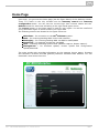
Gateway control
Gateway control helps you:
Monitor the current state of each GSM gateway parts;
Check and set the GSM gateway licence;
View and save the LOG file and CDR.
Firmware / Licence
Use this window to display information on the gateway licence status, firmware and
bootware versions and Ethernet interface MAC address. Use the web interface to
download a new licence via Management–>Licence.
Firmware version – displays the current firmware version for the GSM gateway
connected.
Bootware version – displays the current bootware version for the GSM gateway
connected.
MAC address – shows the MAC address of the GSM gateway Ethernet interface.
CPU serial number – shows the GSM gateway serial number in the
M203–xxxxxxxxxx.bin format.
Active – protocols allowed by the licence:
SIP – SIP support;
MExx – Mobility Extension support, where 'xx' means the maximum count
of users;
G729 – G.729ab voice codec support;
DSS1 – ISDN BRI DSS1 protocol support;
TUN – GSM–CSD remote supervision support.
SMSU – count of SMS users.
SMSS – SMPP support.
SMSE – SMS@email support.
SMSW – SMS via web support.
SNMP – SNMP monitoring support.
Gateway limitation – displays the gateway operation limit (or licence limitation).
Licence status – displays the current licence status (unlocked/locked).
Caution
When the licence code expires, the licence–based protocols will be
locked!
Networks – displays the list of allowed/disallowed GSM/UMTS networks.
Tip
Upon the dealer's request, the gateway may be locked against certain
types of GSM/UMTS networks. This state is signalled by a red LED Ch
1/Ch 2 and a 'netw–err' cause in the GSM module diagnostic window.
Contact your dealer please for more information.
Licence key for gateway – helps you insert a new GSM gateway connection
licence.
2N® TELEKOMUNIKACE a.s., www.2n.cz
50
Caution
By inserting a new licence code you restart the GSM gateway and
discontinue all the currently made calls!
Date / Time
Use this window to set the current date and time for your gateway. Tick Synchronise
with local PC to set the time a date items automatically according to your PC data.
Caution
The internal power source keeps the internal clock source running for
a few hours only! Therefore, check the current gateway date and time
after long BRI gateway disconnection!
2N® TELEKOMUNIKACE a.s., www.2n.cz
51
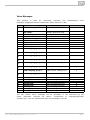
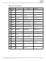
Voice Messages
This window is used for recording, checking and downloading
messages. Supported format is PCM–Alaw, Mono, 8000 Hz, 8 bits.
Index
Type of message
DISA message
Use
Inc. calls from GSM/UMTS
1
ME "Hallo"
Mobility Extension calls
2
3
4
5
6
7
8
ME"Mobility extension"
ME"Please dial number"
ME"Text message"
ME"Activated"
ME"Deactivated"
ME"beeep"
ME"be,be,be"
GSM outgoing group 1
Mobility Extension calls
Mobility Extension calls
Mobility Extension calls
Mobility Extension calls
Mobility Extension calls
Mobility Extension calls
Mobility Extension calls
Calls via Out. GSM group 1
4
4
4
4
4
4
4
8
GSM outgoing group 2
Calls via Out. GSM group 2
8
GSM outgoing group 3
Calls via Out. GSM group 3
8
GSM outgoing group 4
Calls via Out. GSM group 4
8
GSM outgoing group 5
Calls via Out. GSM group 5
8
GSM outgoing group 6
Calls via Out. GSM group 6
8
GSM outgoing group 7
Calls via Out. GSM group 7
8
GSM outgoing group 8
Calls via Out. GSM group 8
8
Message
Message
Message
Message
Message
Message
Message
Message
Voice
Voice
Voice
Voice
Voice
Voice
Voice
Voice
8
8
8
8
8
8
8
8
0
21
22
23
24
25
26
27
28
30
31
32
33
34
35
36
37
30
31
32
33
34
35
36
37
message
message
message
message
message
message
message
message
detector
detector
detector
detector
detector
detector
detector
detector
voice
Max. length(s)
64
4
You can choose which message will be uploaded or use detection by file
name. Detection requires file name: "mess[index of message][optional
remark].wav". You can upload more than one message in .tar file.
2N® TELEKOMUNIKACE a.s., www.2n.cz
52
Note
Voice messages with indexes 30 – 37 are used for detection of the
mobile provider's voice message played before call connection. If a
match is found of the voice message with any of the voice messages
recorded in the gateway, the call is terminated automatically or
established via the last GSM outgoing group set in the LCR table (on
condition that the ITD – Ignore tone detection in last group parameter
is active) in the Gateway Configuration–>LCR table section. Refer
to the Gateway Configuration–>GSM basic parameters–>Voice
message detector settings for details.
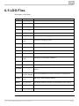
LOG file
The LOG file helps you read out the gateway LOG file. There are LOG file saving and
LOG listing updating icons in the lower part of the window.
Refer to Subs.7, page for details on LOG records.
CDR file
The CDR file helps you read out the gateway Call Data Records (CDR). There are CDR
file saving and CDR listing updating icons in the lower part of the window. Refer to
Subs 6.6, page for details on the CDR format.
Caution
The maximum CDR capacity is 962 records. When this value is
reached, the oldest records will be deleted automatically!
Module status
The window displays the current status of each GSM/UMTS channel. Refer to Subs. 6.4,
page for more details.
Module control
The window helps you control the selected GSM/UMTS module manually.
2N® TELEKOMUNIKACE a.s., www.2n.cz
53
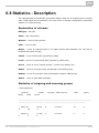
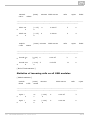
Statistics
The window displays the current statistic data on calls. There are LOG file saving and
LOG listing updating icons in the lower part of the window. Refer to Subs. 6.7, page for
the statistic data format details.
Current call info
The window displays the currently made calls. There are LOG file saving and listing
updating icons in the lower part of the window.
Connection state
The window shows the state of all available configuration sessions. There are LOG file
saving and listing updating icons in the lower part of the window.
AutoCLIP routing table
The window displays the current state of the AutoCLIP table. There are LOG file saving
and listing updating icons in the lower part of the window.
Note
The maximum AutoCLIP routing table capacity is 128 records.
SIP registration
The window displays the current state of the gateway SIP registration.
ISDN lines
The window shows the state of each ISDN BRI interface of the gateway.
Online report
The window provides online GSM gateway tracing.
2N® TELEKOMUNIKACE a.s., www.2n.cz
54
Gateway Configuration
System Parameters
General
Saving call data (CDR) – define the call types for which the GSM gateway shall
store information in the CDR.
Gateway ID – provides 2N® BRI gateway with a numerical code in the CDR in
case multiple devices generate CDRs in the network.
Number for remote control.
Summer / winter time
Automatically move to summer/winter time – enable automatic GSM gateway
system time change for winter/summer time format transition.
Date of move to winter time [dd.mm] – specify the day and month for the
change.
Date of move to summer time [dd.mm] – specify the day and month for the
change.
Mobility Extension (DTMF settings)
Start dialling (quick call forwarding) – set the DTMF code for quick call forwarding
start.
End dialling (quick call forwarding) – set the DTMF code for quick call forwarding
end.
Hold call – set the DTMF code for the current call holding.
Hang up call – set the DTMF code for the current call termination.
'Follow me' activation – activate the Follow me function to make the GSM
gateway start routing calls to the defined GSM/UMTS user number. The default
value is *55.
'Follow me' deactivation – deactivate the Follow me function. The default value
is #55.
'SMS at no answer' activation – activate the SMS at no answer function for a
registered user. The default value is *33.
'SMS at no answer' deactivation – deactivate the SMS at no answer function for
a registered user. The default value is #33.
Tip
Activate/deactivate the SMS at no answer and Follow me functions
by dialling the above mentioned DTMF access codes into the GSM
gateway from a registered mobile user number. You can change the
function values via the configuration interface too (see below).
Others
PIN – set the PIN code for the PIN–secured SIM cards.
2N® TELEKOMUNIKACE a.s., www.2n.cz
55
Caution
A PIN–active SIM card with a PIN value other than that set in the GSM
gateway configuration will be blocked by the gateway with the
'pin–err' cause. Enter the correct PIN on your mobile phone to unlock
the SIM card!
End of dialling (empty=off) – set the DTMF code for DTMF dialling end for DISA
incoming calls. The default value is „#".
List of emergency numbers
The window displays a list of emergency numbers, which are normally routed to the
BRI interface. If the BRI line is disconnected, the emergency numbers are dialled
automatically via any GSM/UMTS module according to the following rules:
Search of a logged–in GSM/UMTS module (regardless of free minutes);
Search of a blocked or network searching GSM/UMTS module.
The table includes an exact format of the number to be called (112,911, etc.). The 'x ' p
laceholder stands for any digit in the number to be called. The '{}'_ placeholder means
the rest of the number. For example:
Format
123
Allowed numbers
123 only
14x0
1400,1410,1420,…1490
999_
All numbers starting with 999
LED indication
GSM signal mode – set the GSM module signal LED indication.
None
Module1 only
Module2 only
All modules
VoIP Parameters
VoIP functions
Day of deleting statistics on VoIP (every month) – set the day for automatic
deletion of call statistics via the VoIP interface. None = statistics will not be
deleted automatically.
2N® TELEKOMUNIKACE a.s., www.2n.cz
56
SIP protocol settings
Use CLIP from INVITE field – define that CLIP from the 'Contact' or 'From' field
shall be used for call routing to GSM/UMTS.
Send 180 ringing instead of 183 session progress.
Send 200 OK instead of 180/183.
Send 200 OK and BYE when rejected from GSM.
Send 200 OK on REGISTER request – virtual registration of device in 2N® BRI
gateway (for registration requiring equipment).
Replace CLIP from GSM with Caller ID.
Deny DTMF according to RFC2833.
Forward DTMF for ME.
SIP registration
Registration expires [s] – set the expiration time for the 2N® BRI gateway
registration data with SIP proxy.
Reattempt registration [s] – set the time interval after which the request shall be
resent.
Registration domain (realm).
Caller ID.
Username – registration data with SIP proxy.
Password – registration data with SIP proxy.
Voice parameters
First RTP port (even: 1024 – 65524) – set the number of the first RTP port. The
RTP port number must be even according to the recommendation.
Last RTP port (even: first RTP+10 – 65534) – set the number of the last RTP
port. The RTP port number must be even according to the recommendation. The
recommended minimum RTP port range is 10.
Codecs settings
Set details for the G.711a/u or G.729 codecs.
Codecs priority
Set the types of the speech codecs to be preferred.
Priority 1
Priority 2
Priority 3
IP addresses
SIP proxy (IP–>GSM) – the SIP proxy IP address from which 2N® BRI gateway
awaits the GSM outgoing call requests.
Tip
If you keep the default values (0.0.0.0), 2N® BRI gateway will
receive requests from any IP address.
2N® TELEKOMUNIKACE a.s., www.2n.cz
57
SIP proxy (GSM–>IP) – the SIP proxy IP address to which 2N® BRI gateway
turns in the case of GSM incoming calls.
SIP registrar – SIP registration server IP address.
Tip
You can use the domain name Registration domain (realm) for the
SIP proxy (IP–>GSM), SIP proxy (GSM–>IP) and SIP registrar
IP addresses on condition that you complete the domain name
Registration domain (realm) and set the DNS server address
properly in the Web configuration–>Ethernet configuration
section. The SIP proxy and SIP registrar IP addresses must be set
to the default value (0.0.0.0).
NAT firewall – NAT firewall IP address.
STUN server – STUN server IP address (Simple Traversal of UDP through NATs
(Network Address Translation)) for obtaining the public IP address with which 2N
®
BRI gateway operates in the Internet. You are recommended to complete this
field if 2N® BRI gateway is installed in a private network separated from the
Internet via NAT or firewall. The pre–set port for sending requests to STUN is
3478.
Next STUN request (60–6553, 0=off) [s] – update of information on the 2N®
BRI gateway public IP address. Use this parameter to configure the frequency of
queries routed to the STUN server.
Note
In case the GSM gateway is installed behind the NAT, make proper
routing settings in the NAT router for the relevant ports (SIP, RTP,
STUN). Integrated firewalls can also affect VoIP calls!
Tip
Should you have call troubles (such as unilateral audibility, connection
errors), make sure that all the active elements on the VoIP call route
have been set properly. For easy troubleshooting, try the
point–to–point connection with the software IP phone (SJ phone, e.g.)
in your PC and, at the same time, apply network analyzer tracing
(WireShark – www.wireshark.org).
Refer to Subs 5.1 for easy tracing by the BRI gateway.
Tones generated to VoIP
Ring tone to VoIP – enable generation of a user ring tone or transfer of the real
ring tone from the GSM/UMTS networks.
ISDN Parameters
Use this window to set the BRI ISDN port parameters. The appearance and count of
the parameters may be different in 2N® BRI Lite and 2N® BRI Enterprise due to
different counts of ISDN BRI ports.
BRI mode selection
Mode – set the BRI1 and BRI2 (for 2N® BRI Enterprise only) ports.
2N® TELEKOMUNIKACE a.s., www.2n.cz
58
BRI1 and BRI2
TEI Address – set a fixed TEI address for connection of port(s) in the
Point–to–Point mode.
MTP – activate assignment of the dynamic TEI address (Point–to–Multipoint
mode).
Progress indicator value – set the value for each progress element for call setup.
Please respect the PBX and PSTN settings to avoid wrong evaluation of messages sent
by the BRI gateway and, subsequently, call setup errors. Refer to the table for the
decimal numbers to be assigned to the progress messages.
Number
Meaning
OFF
Progress element is not sent in the message
1
Connection is not end–to–end ISDN, following progress messages will be
sent in the speech band
2
Call destination address is not ISDN
3
Call initiator address is not ISDN
4
Call is returning to ISDN
8
Communication between interconnected systems has lead to a change of
the telecommunication service (for end–to–end ISDN connection only)
10
Delay due to speech interface
BRI functions
Day of deleting statistics on BRI (every month) – set this item to '0' to disable
periodical (monthly) deleting of statistics. Set this value to 'x' other than '0' to
enable deletion of statistic data on x–th day of a month.
Digits count in SETUP (en–block) – set the count of outgoing dialling digits to be
sent by the gateway in the SETUP message in the ENBLOCK format. The
remaining digits will be sent in the OVERLAP format, i.e. in the information
element following the SETUP message. The OVERLAP mode is used in analogue
networks.
Example:
SETUP digit count: 7, user number: 601234567
Call setup messages:
SETUP (601234567)
INFO (6)
INFO (7)
Receive dial number from Subaddress – use this parameter to receive dialling
from the subaddress element instead of standard CDN.
2N® TELEKOMUNIKACE a.s., www.2n.cz
59
Don't send Connect ACK on TE – use this parameter to enable/disable sending of
the CONNECT ACK message to the TE port.
Use CLIR if requested from ISDN (SETUP) – enable automatic CLIR resending to
GSM/UMTS if required so by the ISDN.
Tone signalling for calls from ISDN
Dial tone to BRI1 with empty SETUP – set the dial tone type to be generated by
the BRI gateway.
Ring tone – set the ring tone type to be generated by the BRI gateway.
Generate busy tone to BRI1 – set the busy tone type to be generated by the BRI
gateway into the BRI 1 interface.
Generate busy tone to BRI2 – set the busy tone type to be generated by the BRI
gateway into the BRI 2 interface.
Numbering plan settings
CDN, CGN – use these parameters to set the Numbering plan for the called (CDN)
and calling (CGN) numbers.
Binary value
0000
Decimal value
0
Description
Unknown numbering plan
0001
1
ISDN/Telephony numbering plan
0011
3
Sata numbering plan
0100
4
Telex numbering plan
1000
8
National standard numbering plan
1001
9
Private numbering plan
1111
15
Reserved for Extension
Port modes
This item helps you set each of your gateway ports. The settings are based on the LCR
table including relevant routing/rejecting rules for all incoming and outgoing calls.
ISDN Parameters – Monitoring
BRI1 alerts
Still activated ISDN layer 1 – enable/disable keeping of ISDN layer 1 active.
Still activated ISDN layer 2 (SABME/UA) – enable/disable keeping of ISDN
layer 2 active.
Send SMS at state changes – enable/disable alert sending upon BRI1 state
change.
BRI2 alerts
2N® TELEKOMUNIKACE a.s., www.2n.cz
60
Still activated ISDN layer 1 – enable/disable keeping of ISDN layer 1 active.
Still activated ISDN layer 2 (SABME/UA) – enable/disable keeping of ISDN
layer 2 active.
Send SMS at state changes – enable/disable alert sending upon BRI1 state
change.
BRI common settings
Timeout for ISDN line deactivation detection [s] – an SMS alert
on BRI1/BRI2 deactivation is sent after this timemout.
Timeout for ISDN line activation detection [s] – an SMS alert on BRI1/BRI2
activation is sent after this timeout.
Numbers where SMS will be sent to – list of numbers to which the SMS alert
shall be sent.
Text of SMS – SMS alert text with the following parameters:
%P(x|y), where "x" represents any text concerning BRI1 and "y"
represents any text concerning BRI2.
%A(x|y), where "x" represents any text for interface deactivation and "y"
represents any text for interface activation.
Settings of Alive SMS interval
Send Alive SMS – enable/disable sending of ALIVE SMS.
Time [hh:mm] – ALIVE SMS sending time.
Days interval – ALIVE SMS sending interval.
Numbers where SMS will be sent to – list of numbers to which the ALIVE SMS
shall be sent.
Text of SMS – ALIVE SMS text.
GSM Basic Parameters
Number of digits dialled from VoIP
Minimum numbers from VoIP – set the minimum count of digits to be dialled into
the GSM network.
Maximum numbers from VoIP – set the maximum count of digits to be dialled
into the GSM network.
Wait for next digit [s] – set the timeout for 2N® BRI gateway to wait for the
next digit dialled from VoIP to GSM.
Calls
Relax timeout [s] – set the timeout between the end of the last call and
beginning of the next call made via one and the same GSM module (incoming
and outgoing calls are rejected during this timeout). The recommended relax
value is 2 seconds – please do not change this setting unless absolutely
necessary.
Timeout for ringing to GSM [s] – ringing timeout for outgoing calls to GSM. If not
answered or terminated within this timeout, the call will be terminated
automatically by the gateway when this timeout elapses.
2N® TELEKOMUNIKACE a.s., www.2n.cz
61
Holiday list
List of days on which calls will be routed like on weekends in the LCR.
DTMF settings
Minimum delay between two identical DTMF characters [s/100] received.
Tone detector settings
The GSM gateway can automatically detect user defined tones transmitted by
GSM/UMTS for setting up outgoing calls to the GSM/UMTS networks. In general, they
are tones of a transferred number. For the purpose of such detection, the GSM
gateway automatically terminates the call and tries to set it up via another available
outgoing group (if defined in the LCR).
Frequency 1;2;3;4 – define the frequencies for the tone to be detected.
Sequence list – set the sequence of the tones to be detected.
Voice message detector settings
Minimum percent to match – set the match percentage range in which the voice
message is detected as identical with one of the voice messages recorded in the
Gateway control–>Voice messages section under index 30 - 37. The
recommended value is 70-90%.
Voice parameters of GSM modules
Set the voice level in the gateway GSM modules.
Audio level DSP
Set the voice level for calls in the gateway signal processor.
Output audio level DSP [dB] – audio volume gain/loss to VoIP
Input audio level DSP [dB] – audio volume gain/loss to GSM
Caution
An extremely high voice level may lead to poor voice quality
(distortion, echo, etc.) and wrong DTMF detection!
Tone generated for incoming calls from GSM/UMTS
Dial tone – set the dial tone for incoming calls from GSM/UMTS.
Ring tone – set the ring tone for incoming calls from GSM/UMTS.
Generate busy tone to GSM/UMTS – enable busy tone generation for call
termination.
2N® TELEKOMUNIKACE a.s., www.2n.cz
62
Caution
If the Generate busy tone function is enabled, the duration of
outgoing calls billed by the GSM/UMTS provider will be extended!
Error GSM/UMTS causes
Set the ISDN release cause for each of the below mentioned statuses. Every call
that meets any of the below mentioned requirements, will be rejected with a user
defined cause (the ISDN cause number will be translated to VoIP as a SIP code
as defined below).
Lack of digits in OVERLAP mode – any call that fails to meet the minimum
digits count requirement will be rejected.
Restricted number prefix – any call whose prefix is not included in any of
the prefix lists will be rejected.
Selected module / GSM group is not ready – a call will be rejected in case
there is no available GSM module in the selected (by LCR) outgoing GSM
group.
Selected module / GSM groups are not ready – a call will be rejected in
case there is no available GSM module in the selected (by LCR) outgoing
GSM groups.
Cause translation
The release cause received from GSM/UMTS can be converted into another ISDN
release cause. The resultant ISDN cause number will be converted into a SIP code
according to the table below:
2N® TELEKOMUNIKACE a.s., www.2n.cz
63
Conversion table:
ISDN cause
value
1
Unallocated number
SIP
code
410
3
No route to destination
404
Not found
6
Channel unacceptable
503
Service unavailable
16
Normal call clearing
BYE
17
User busy
486
Busy here
18
No user responding
480
Temporarily
unavailable
19
No answer from user
480
Temporarily
unavailable
21
Call rejected
603
Decline
22
Number changed
410
Gone
27
Destination out of order
404
Not found
28
Address incomplete
484
Address incomplete
29
Facility rejected
501
Not implemented
31
Normal, unspecified
BYE
34
No circuit available
503
Service unavailable
38
Network out of order
503
Service unavailable
41
Temporary failure
503
Service unavailable
42
Switching equipment
congestion
503
Service unavailable
44
Requested facility not
subscribed
503
Service unavailable
47
Resource unavailable
503
Service unavailable
50
Requested facility not
subscribed
503
Service unavailable
55
Incoming class barred within
CVG
603
Decline
Description
2N® TELEKOMUNIKACE a.s., www.2n.cz
Description
Gone
64
57
Bearer capability not authorised 501
Not implemented
58
Bearer cap, unavailable at
present
501
Not implemented
63
Service or option unavailable
503
Service unavailable
65
Bearer cap, not implemented
501
Not implemented
79
Service or option not
implemented
501
Not implemented
87
User not member of CVG
603
Decline
88
Incompatible destination
400
Bad request
98
Invalid message
400
Bad request
102
Recover on timer expiry
408
Request timeout
XXX
Other received CAU from netw.
500
Internal server error
Others
Text of SMS at no answer – edit the text of the SMS to be sent to the calling
party in case of no answer (if the function is active). The %N string will insert the
CLIP received from VoIP in the SMS text.
Text of SMS for all calls – complete this parameter to make the GSM gateway
send SMS to every called party regardless of whether or not the call was
successfully connected. The %N string will insert the CLIP received from VoIP in
the SMS text.
Save received SMS to – select the storage for received SMS messages.
SIM card identification – set the SIM Id (IMSI/SCID) to be entered in the CDR.
Disable CLIP from GSM/UMTS to VoIP – enable/disable resending of the CLIP
from GSM to VoIP.
Reject call with CHLD – enable rejection of incoming calls from GSM/UMTS via
AT+CHLD (subscriber busy) instead of standard ATH.
GSM Group Assignment
Here you can assign the GSM/UMTS modules to groups. You can assign incoming and
outgoing calls separately using the parameters below.
GSM Outgoing Groups
2N® BRI gateway allows you to work with two groups of outgoing calls. You can set
different values (call setup, called minutes and sent SMS per period, etc.) for each of
them.
General settings
Delay for CONNECT [s] – set the delay between receiving a GSM call and sending
2N® TELEKOMUNIKACE a.s., www.2n.cz
65
the CONNECT message.
Minimum ring duration to send SMS at no answer [s] – set the minimum ringing
timeout for sending the SMS at no answer.
Note
The INVITE message must contain the called and calling numbers in
order that the SMS at no answer function may work properly.
Delay for ALERTING [a] – set the delay before sending the ALERTING message.
Minute parameter – define whether the GSM gateway shall consider call duration
or count while limiting outgoing calls.
Day of deleting statistics in group (every month) – set a day on which statistic
data on disconnected calls shall be deleted.
Generate virtual ring tone – enable/disable generation of the virtual ringing tone
into the VoIP interface.
Call length counting – define whether call minutes or seconds shall be counted.
BTS lock – identify the BTS to which the GSM modules shall log in. Restart the
selected GSM modules to execute the changes.
Caution
The BTS lock service work with specific GSM modules only (Q55)!
If you set a wrong BTS lock, the selected GSM module(s) will not log
in to GSM.
After call relax delay – set the time between the end of the current call and start
of the next call via one and the same GSM/UMTS module. The recommended
value for heavy–traffic installations is 2 seconds!
Add random time – use this auxiliary parameter to add random time in seconds.
Thus, the resultant time is the sum of the two above mentioned parameters.
Disconnect call
Set the reasons for immediate discontinuation of an outgoing call to GSM/UMTS.
Send CLIP from VoIP to GSM/UMTS
Transfer CLIP to GSM/UMTS – enable/disable the function.
Separating char – define the CDN/CLIP separating character.
Modify (‘–’ remove one digit) – change the CLIP. The ‘–’ character is used for
deleting one character from the left.
Caution
The Send CLIP from VoIP to GSM service must be supported by the
GSM/UMTS provider's network. Otherwise, the call may be rejected by
GSM/UMTS!
GPRS activation
APN string – define the Access Point Name (APN) for GPRS connectivity.
2N® TELEKOMUNIKACE a.s., www.2n.cz
66
Basic settings
Roaming enabled for network code – international code for the roaming enabled
network. The code consists of the following two numbers:
MCC – Mobile Country Code – national code (Czech Republic – 230, e.g.)
MNC – Mobile Network Code – GSM network code (T–Mobile 01, O202,
Vodafone 03, e.g.)
Hence, the T–Mobile CZ international code is 23001. Leave the field empty to disable
roaming.
String
<empty>
Note
Roaming disabled
2300
Roaming disabled (five digits at least)
23002
Roaming enabled for the 23002 (MCC+MNC) network
230XX
Roaming enabled for the 23000 – 23099 (MCC+MNC) network
XX001
Roaming enabled for the 00001 – 99001 (MCC+MNC) network
XXXXX
Roaming enabled for any network
Note
Before enabling roaming, please use your mobile phone to make sure
that the GSM/UMTS searching priorities have been set properly on the
SIM card.
Caution
Calls via a roaming network may increase your telephone call costs!
CLIR – enable/disable presentation of the SIM CLI on the called party's
telephone. CLIR is recommended for the SIM card inserted in the GSM module to
avoid CallBack problems.
Caution
The Temporary CLIP enable and Temporary CLIR enable services
must be supported by the GSM/UMTS provider's network. Otherwise,
the call may be rejected by GSM/UMTS!
Maximum number of called minutes – define the maximum count of minutes to
be called within a month via the selected SIM card.
SMS messages number – define the maximum count of SMS messages to be sent
within a month via the selected SIM card.
Day of restoring call limit and delete statistics – select a day in a month on which
the Max count of called minutes and Count of SMS messages statistics shall
be deleted.
First count – set the length of the first pulse after which the pulse counting
change starts as defined in the Next count parameter.
Next count – set the length of one pulse in seconds after the time defined in the
First count parameter elapses.
2N® TELEKOMUNIKACE a.s., www.2n.cz
67
Note
Set the two parameters above (First count, Next count) properly to
count free minutes on SIM cards correctly. These parameters are used
for limiting outgoing calls depending on free minutes. The CDRs
contain real data.
Day limit of called minutes – set the maximum count of minutes to be called
within a day via the selected SIM card.
Time limits
There are two SIM use time limits in a GSM group.
Call tariffs
Use this function to assign up to four independent free minute counters to a group of
GSM modules (SIM cards), e.g.:
Tariff 1 = free minutes for calls to own GSM/UMTS network;
Tariff 2 = free minutes for calls to other GSM/UMTS networks;
Tariff 3 = free minutes for calls to fixed network;
Tariff 4 = free minutes for calls within a closed user group (VPN).
Complete the LCR table (assign prefixes to tariffs) properly to make full use of this
function. If routing to a tariff is not used, the global free minutes function will be used
in the LCR table.
Free minutes Set the free minutes for the tariff offered by the provider.
Transferred minutes Set the maximum count of free minutes to be transferred
to the next period.
Day of restoring free minutes Set a day on which the free minute counters
will be reset automatically. Select every 24 hours, a day in a month, or a day in a
week.
Week of restoring free minutes in month Set a week in which the free
minute counters will be reset automatically. Set the week number only if the
restoration takes place every other Friday in a month, e.g., or keep Every for
the other cases.
Caution
The recommended free minute counter value is X–5, where X is the
number of free minutes obtained from the GSM/UMTS provider. Thus,
you can avoid exceeding limits.
The manufacturer is not responsible for additional call costs incurred
as a result of exceeding your GSM/UMTS provider's free minute/SMS
limit.
GSM Incoming Groups
2N® BRI gateway allows you to work with two groups of incoming calls. You can set
different values for each of them.
2N® TELEKOMUNIKACE a.s., www.2n.cz
68
General settings
Mode – set how the gateway shall process incoming calls from the GSM network.
Reject incoming calls – all incoming calls from the GSM network are
rejected automatically.
Ignore incoming calls – all incoming calls from the GSM network are
ignored. The calling party hears the check ring tone.
Accept incoming calls + voice message – incoming GSM calls are accepted
by the gateway and, if programmed so, DTMF with a voice message is
activated for them.
Accept incoming calls + dialtone – incoming GSM calls are accepted by the
gateway and, if programmed so, DTMF with a simulated second dialtone is
activated for them.
CallBack after ring / Reject – CallBack will be made if the CLIP is included
in the CallBack table. The other incoming calls will be rejected.
CallBack after ring / Ignore – CallBack will be made if the CLIP is included
in the CallBack table. The other incoming calls will be ignored.
Report to PC + voice message – the GSM gateway sends information on
the incoming call to a PC equipped with call routing application. If
programmed so, DTMF with a voice message is activated for the incoming
call.
Report to PC + dialtone – the GSM gateway sends information on the
incoming call to a PC equipped with call routing application. If programmed
so, DTMF with a simulated second dialtone is activated for the incoming
call.
Minimum digits in DTMF – set the minimum count of digits to be requested by the
gateway for DTMF.
Maximum digits in DTMF – set the maximum count of digits to be accepted by
the gateway for DTMF.
Timeout for entering DTMF digits [s] – set the timeout for which the GSM
gateway shall wait for the first/next DTMF digit. If you select '0', the incoming
call will be automatically connected to the numbers included in the List of called
numbers.
Day of deleting GSM group statistics – set a day in a month on which the
incoming call statistics shall be deleted.
Prefix before DISA – set a numerical prefix to precede DTMF.
CLIP – use this parameter to modify the incoming CLIP from GSM/UMTS. For
international codes, '+' will be removed automatically. Use '–' to remove a digit.
Examples (CLIP in GSM: +420600123456):
Null
CLIP to VoIP/PRI
1
420261301500
No CLIP change
+
+420261301500
Add + before CLIP
00
00420261301500
Add 00 before CLIP
–
0261301500
First two digits removed from CLIP
–––99
99261301500
First three digits removed from CLIP, prefix 99
added
Parameter
2N® TELEKOMUNIKACE a.s., www.2n.cz
Note
69
Looping of voice message – set the voice message playing time.
Send CLIP from GSM/UMTS to VoIP
Transfer CLIP from GSM/UMTS – enable/disable the function.
Separating char – set the separator for the SIM card CLIP and ID of the
extension to be called.
Modify – modify the extension ID.
Caution
The Send CLIP from VoIP to GSM service must be supported by the
GSM/UMTS provider's network. Otherwise, the call may be rejected by
GSM/UMTS.
Others
Time to keep CLIP in table – set the record keeping time for AutoCLIP routing.
Add record only for unconnected call – enable storing of unconnected outgoing
calls in the AutoCLIP table only.
Delete record for connected answer – enable deletion of an AutoCLIP record in
the case of successful CallBack.
Skip DTMF for numbers not in CLIP Routing table – enable this option to set
DTMF to the incoming calls only whose CLIP is included in the CLIP Routing table.
Skip list of called numbers after failed call to wanted number – enable this
function to disable forwarding of incoming calls to the numbers included in the
List of called numbers if rejected after DTMF.
Auto end to CallBack request – enable that the incoming call whose CLIP meets
the CallBack settings will be rejected. If not, the call will be ignored. The CallBack
function will be retrieved after call end in both the cases.
List of called numbers
List of numbers to be dialled if DTMF dial–in was not made. Search the table from top
to bottom. If the called user is inaccessible, use the following table record.
Prefixes
Use this window to adapt the gateway to calling to various GSM providers' networks.
Set the call routing rules based on prefixes for up to eight groups.
Prefix list 1–8
Eight prefix groups to be assigned in the LCR table.
Basic settings
GSM network ID – set the prefix list user code for easier orientation in the LCR.
Default count of digits – default length of the number to be dialled into the
GSM/UMTS networks for routing via the selected prefix list. Use this parameter in
case the Digits count is not included in the Accepted prefixes table.
2N® TELEKOMUNIKACE a.s., www.2n.cz
70
Table of replaced prefixes
Use this table to replace the prefix of the received number ('00' with '+', e.g.). You can
only add or remove the prefix. This change is made before the prefix is searched for in
the prefix table. Be sure to keep the „/" record in the table for a proper function.
Table of accepted prefixes
List of prefixes of called destinations to which the selected prefix list applies.
Note
The maximum count of Accepted Prefixes table records is 128.
LCR Table
The Least Cost Routing (LCR) table helps you route calls according to the called party
number, time and days in a week.
Prefix list – prefixes to be used for a selected LCR row.
Time limitation – time validity limitation for a selected LCR row.
Weekend usage – enable/disable a row on weekends.
Maximum length of call – set the maximum duration (minutes) for an outgoing
call to the GSM/UMTS network.
Groups – outgoing GSM groups used for the selected LCR row.
Fallback port (9): set the fallback port. If the fallback port service is
unavailable, the next LCR table row is applied. Select the appropriate
routing rule to set the fallback port in the Gateway configuration–>Port
modes.
Tariffs – select the tariff group (free minute counter) to be used for the outgoing
call. Refer to the GSM outgoing groups subsection for details.
Ignore tone detection in last group – having detected a user defined tone (refer
to GSM basic settings), the GSM gateway automatically terminates the call and
seeks for another call setup way. If this parameter is activated, the GSM gateway
ignores the tone detection results and sets up a call when this is the only possible
call establishing way.
Note
If you use tariff routing, set the tariffs properly in the GSM outgoing
groups subsection
The maximum count of LCR table records is 64.
CLIP Routing Table + CallBack
Use the table to set a fixed CLIP assignment of incoming CLIPs from GSM to the
numbers of extensions to which incoming calls are routed automatically. Also, set the
CLIP list in the GSM network for which CallBack is enabled.
GSM number (CLIP) – user Id in GSM/UMTS.
Autodial – enable/disable CLIP routing for the selected CLIP.
2N® TELEKOMUNIKACE a.s., www.2n.cz
71
Dial to VoIP – VoIP destination number for the CLIP routing function.
Auto CallBack – enable/disable CallBack routing for the selected CLIP.
Limit – set the maximum call duration (minutes).
Note
Remember to activate the CallBack mode in the GSM incoming
groups for a proper function.
The maximum count of CLIP routing table records is 96.
Mobility Extension
Use this table to register the Mobility Extension users.
Name – user name for calling to VoIP.
User – registration user name for VoIP.
Password – registration user password for VoIP.
GSM number (CLIP) – user SIM card CLIP.
Follow me function – enable/disable call forwarding to the user mobile station
(according to CLIP).
SMS at no answer function – enable/disable sending of SMS on missed calls.
Ethernet Configuration
Use this window to set the gateway Ethernet interface.
Use DHCP – enable/disable the DHCP client function for 2N® BRI gateway.
IP address – fixed IP address (v4) for the 2N® BRI gateway Ethernet interface.
Subnet mask – network mask for the 2N® BRI gateway Ethernet interface.
Default gateway – IP address (v4) of the IP gateway in the Ethernet.
DNS server1 – primary DNS server.
DNS server2 – secondary DNS server. Used as a back-up when DNS server 1 is
not functional.
Caution
Saving wrong values, e.g. DHCP enable, may result in making the 2N
®
BRI gateway configuration part inaccessible. In that case, reset the
GSM gateway to factory values; refer to Subs.4.1.
Tip
If the gateway is in the DHCP client mode, the current values obtained
from the DHCP server are displayed in the IP address, Subnet mask
and Default gateway items.
Login Configuration
Use this window to set the access password and name for the 2N® BRI gateway web
interface. Use the same access data for Telnet connection too.
2N® TELEKOMUNIKACE a.s., www.2n.cz
72
Caution
Change the user name and password during your first gateway
configuration to avoid unauthorised access to your gateway
configuration!
Web Configuration
Set additional parameters for web access to the GSM gateway.
Auto logout – set the count of minutes in which the user will be logged out
automatically.
Enable web session lock – one Admin user may be connected to the GSM
gateway at one time. If another duly authorised user tries to log in, the
preceding session will be terminated automatically. If you activate this function,
no automatic logout will occur and any other access attempts will be blocked.
Simple login form – activate this item to change the graphic appearance of the
login window into an anonymous look. This function is recommended for direct
connection of the GSM gateway to the Internet.
Use SMS user for SMS operations on the web – enable/disable a user authorised
to send/receive SMS messages only.
SMS user name/password – connect a user with the right to receive/send SMS
only.
Report Configuration
Use the window to set details for automatic tracing generated by the GSM gateway.
2N® TELEKOMUNIKACE a.s., www.2n.cz
73
Messaging
This group helps:
Set the GSM gateway to send/receive SMS via SMTP/POP3 or SMPP
Define the routing rules for incoming and outgoing SMS messages
Check the GSM gateway SMS database filling capacity
Caution
This service is file-licensed. Refer to Management–>Licence key for
the current GSM gateway licence details.
Modules Grouping
Global settings
SMS server enabled – enable/disable the SMS server at the GSM gateway
(keep disabled if you select another SMS processing method).
AutoCLIP routing expires [hours] (1-10000, 0=off) – set the maximum
time for keeping of the automatic SMS routing record (response) in the AutoCLIP
table.
Modules to SMS groups assignment
This section helps you assign GSM modules to SMS groups (according to the GSM
provider, e.g.) to facilitate incoming/outoging SMS routing.
SMS groups to User groups assignment
This section helps you assign SMS groups to User groups for SMS sending/receving
purposes. The GSM gateway can contain up to four User groups.
2N® TELEKOMUNIKACE a.s., www.2n.cz
74
Caution
The count of user accounts is file-licensed. Refer to
Management–>Licence key for the current GSM gateway licence
details.
Users
This section helps you manage the SMS users. Select a communication protocol for
user adding (SMTP/POP3 or SMPP).
Add user
User group – assign the user to a User group.
User full name – define the system user name.
Replace dial for outgoing SMS – define the number (CPN) to which the
user's outgoing SMS messages shall be sent.
Access type – select the communication protocol for SMS processing:
Email (SMTP/POP3) – use SMTP for SMS sending and POP3 for
SMS receiving.
SMPP (SMSC) – set the GSM gateway into the 'SMS centre' mode.
SMPP (ESME) – set the GSM gateway into the 'ESME - External
Short Messaging Entity' mode.
Login name (without domain) – define the login name for the client
Email.
System ID – SMSC user ID.
Password – SMSC/SMTP user password.
System ID (for authentication on remote side) – ESME user ID.
Password (for authentication on remote side) – ESME user ID.
TCP type – set the TCP parameter into the client/server mode.
Server address – set the server IP address and TCP server transport
port.
Message direction of Esme – set the ESME user details:
Transceiver – ESME works as a transmistter/receiver.
Transmitter – ESME works as a transmitter.
Receiver – ESME works as a receiver.
Address range – set this parameter if required so by SMSC for SMS
receiving.
Delivery status required – set the SMS sending request for outgoing
SMS delivery confirmation.
Send message as Flash SMS – activate the Flash SMS function for
outgoing SMS messages.
Note
You can set the Delivery status required parameter only if the
SMTP/POP3 protocol is used.
With SMPP, the delivery information is active automatically in case the
service is required by the SMPP counterparty or via an incoming SMS
message from the GSM/UMTS network.
2N® TELEKOMUNIKACE a.s., www.2n.cz
75
User Group
This section helps you edit the User group and set the routing rules for the group's
incoming and outgoing SMS.
General settings
Set the basic parameters for SMS sending via SMTP/POP3 or SMPP.
Optional informations
Description – set the User group details.
Identical SMS limit – set the check of identical SMS messages, i.e. sequentially
sent messages with identical SMS PDUs. When the set limit is exceeded, the
excessive SMS messages are discarded without being sent.
2N® TELEKOMUNIKACE a.s., www.2n.cz
76
Email settings
Domain – define the domain name for SMS sending/receiving via SMTP/POP3.
POP3 - Subject of email – set the message subject to be added automatically
to the SMS loaded from the GSM gateway via POP3.
POP3 - Subject of email (delivery acknowledgement) – set the SMS
delivery acknowledging message subject.
POP3 - Subject of email (not delivered) – set the SMS non-delivery
acknowledging message subject.
POP3 - Subject of email (send error) – set the SMS sending failure message
subject.
SMTP - Maximum SMS per email – set the maximum count of SMS messages
to be sent within one Email message. Any characters exceeding the set length
will be ignored.
SMTP - Add "From" to SMS – add 'From' from the Email message to the
outgoing SMS. The sender information will be displayed at the beginning of the
SMS message.
SMTP - Add "Subject" to SMS – add 'Subject' from the Email message to the
outgoing SMS. The subject information will be displayed at the beginning of the
SMS message.
2N® TELEKOMUNIKACE a.s., www.2n.cz
77
SMPP address modification
Source address of message incoming from SMPP – set how to modify the
message sender ID received via SMPP.
Never replace original address
Replace if the original address is empty
Always replace original address
address – enter sender's new ID
TON – type of number
NPI – numbering plan indicator
Destination address of message incoming from SMPP – set how to modify
the message addressee telephone number received via SMPP.
Never replace original address
Replace if the original address is empty
Always replace original address
address – enter addressee's new telephone number
TON – type of number
NPI – numbering plan indicator
Source address of message outgoing to SMPP – set how to modify the
message sender ID to be sent via SMPP.
Never replace original address
Replace if the original address is empty
Always replace original address
address – enter sender's new ID
TON – type of number
NPI – numbering plan indicator
Destination address of message outgoing to SMPP – set how to modify the
message addressee telephone number to be sent via SMPP.
Never replace original address
Replace if the original address is empty
Always replace original address
address – enter addressee's new telephone number
TON – type of number
NPI – numbering plan indicator
2N® TELEKOMUNIKACE a.s., www.2n.cz
78
Incoming SMS routing
This section helps you set the incoming SMS routing rules, which are included in the
incoming SMS routing table.
Add record
Disabled – enable/disable the selected routing rule.
Message from SMS group – select the SMS group that receives the SMS.
Action type – select the action for the received SMS:
Autoclip routing – the incoming SMS will be routed according to the
AutoCLIP table records.
Deliver to user – the SMS will be delivered to the selected user.
Drop message – the SMS will be dropped.
Deliver to user – select the SMS addressee. This option is valid only if Action
type = Deliver to user is selected.
Time limitation – set the rule validity time.
Days limitation – set the days in a week on which the rule shall be valid.
Clip mask – set the filter for the SMS sender telephone number (CLIP). If the
selected mask matches the CLIP, the SMS will be routed according to the rules
set above. If not, the SMS will be dropped. The * character replaces any string of
characters (789789789=789*, e.g.). The ? character replaces any character
(789789789=789??????, e.g.).
Text begin – set the string to be matched against the SMS text beginning. If a
match is found, the SMS will be routed according to the rules set above.
Note
The rules are applied to incoming SMS sequentially, starting from the
first rule. If all the set rules are met in a row, the SMS is routed
according to the row.
2N® TELEKOMUNIKACE a.s., www.2n.cz
79
Outgoing SMS routing
This section helps you define the outgoing SMS routing rules, which are included in the
outgoing SMS routing table.
Add record
Disabled – enable/disable the selected routing rule.
Message to SMS group – select the SMS group via which the SMS will be sent.
Action type – select the action for the outgoing SMS:
Submit from user – enable sending SMS from the selected user.
Submit from all users – enable sending SMS from all the SMS group
users.
Submit from user – select the user in case Action type = Submit from user
is selected.
Time limitation – set the rule validity time.
Days limitation – set the days in a week on which the rule shall be valid.
Dial mask – set the filter for the SMS addressee telephone number (Dial). If the
selected mask matches the Dial, the SMS will be routed accroding to the rules set
above. If not, the SMS will be rejected and deleted. The * character replaces any
string of characters (789789789 = 789*, e.g.). The ? character replaces any
character (789789789 = 789??????, e.g.).
Text begin – set the string to be matched against the SMS text beginning. If a
match is found, the SMS will be routed according to the rules set above.
Note
The rules are applied to outgoing SMS sequentially, starting from the
first rule. If all the set rules are met in a row, the SMS is routed
according to the row.
2N® TELEKOMUNIKACE a.s., www.2n.cz
80
Control
This section helps you monitor the system. It includes storage filling information and
AutoCLIP records.
SMS queues
The subsection displays the current SMS storage state.
Incoming SMS database
The subsection displays current information on the incoming SMS storage filling
percentage and maximum count of incoming storage records.
Caution
The POP3 protocol enables you to set how long a copy of the loaded
message shall be kept in the SMS server. The SMS keeping time
depends on your e–mail client setting. Make sure that you have
chosen a correct time value to avoid database overfilling. When the
storage has been filled up, no new SMS messages will be received!
Outgoing SMS database
The subsection displays current information on the outgoing SMS storage filling
percentage and maximum count of outgoing storage records.
User table
The table shows the count of incoming and outgoing SMS stored in the
above-mentioned databases from the user's point of view and helps you delete the
SMS stored.
User table items:
Incoming SMS count – Received / Ack OK / Ack error / Failed
Received – count of received common SMS messages
Ack OK – count of SMS delivery acknowledging messages
Ack error – count of SMS non-delivery acknowledging messages
Failed – count of SMS sending failure messages (failed due to network
error, invalid number, etc.)
Outgoing SMS count – Waiting / Sending /Sent
Waiting – count of waiting SMS messages
2N® TELEKOMUNIKACE a.s., www.2n.cz
81
Sending – count of currently sent SMS messages
Sent – count of sent SMS messages waiting for delivery acknowledgement
AutoCLIP routing table
The window displays the current state of the AutoCLIP table.
2N® TELEKOMUNIKACE a.s., www.2n.cz
82
SMTP/POP3 Basic Configuration – Step by Step
This section helps you define the 2N® BRI basic parameters for SMS sending/receiving
via SMTP/POP3. Read the Messaging subsection carefully before setting details.
Figure 1 shows sending/receving SMS via SMTP/POP3. Having created user accounts
in 2N® BRI, the users can access the accounts via the e-mail client and send SMS
messages to 2N® BRI via SMTP. The gateway receives the messages and resends
them to the GSM users according to the predefined routing rules.
A message coming to 2N® BRI from GSM is routed according to the incoming SMS
rules and delivered to the user via POP3.
Figure 1: SMTP/POP3 Communication
Note
You can send an SMS message of any length to up to 100 users at the
same time from the e-mail client. The maximum SMS count per e-mail
is only limited by the User group–>General settings SMTP–>
Maximum SMS per email settings.
Take the following basic steps in 2N® BRI to enable SMS sending/receiving:
1. In the Monitoring–>SMS grouping menu:
a. Assign the selected GSM modules to the SMS groups (according to the GSM
provider and SIM cards with identical tariffs, for example).
b. Assign the SMS groups created in step 1.a above to the User groups if you
use messaging with different routing rules to different company
departments, for example.
2. Add users in the Monitoring–>Users–>Add menu:
a. Assign the user to a User group.
b. Set Access type: Email(SMTP/POP3).
c. Define the Login name (without domain) and Password to log in to the
2N® TELEKOMUNIKACE a.s., www.2n.cz
83
2.
c.
SMS server via your e–mail client.
3. Set the Domain in the Messaging–>User Group–>General settings–>Email
settings–>Domain menu.
a. Set the user domain. The domain is automatically assigned to the user
name in the selected User group and represents the user e–mail address.
Example: Suppose a user was created in step 2.c with Login name: USER
and domain Domain: email.com, then the e-mail address of the user
with the right to access the SMS server will be [email protected]. The @
character is completed automatically and is not included in the Domain:
field.
4. Create the incoming SMS routing rules in the Messaging–>User
Group–>General settings–>Incoming SMS routing–>Add menu:
a. Select the group to receive the SMS via the Message from SMS group.
b. Select the Action type to define how to process incoming SMS. Example:
Set Action type: Deliver to user to deliver SMS to selected users.
c. Set Deliver to user to define the SMS receiving user.
5. Create the outgoing SMS routing rules in the Messaging–>User
Group–>General settings–>Outgoing SMS routing–>Add menu:
Enable the SMS server in the Messaging–>Modules grouping–>SMS server
enabled menu.
a. Set the SMS group via which the outgoing SMS will be routed in the
Message to SMS group menu.
b. Select the Action type to define how to process outgoing SMS. Example:
Set Action type: Submit from user to send SMS from selected users.
c. Set Submit from user to define the SMS sending user.
Should you get in troubles, follow the steps below please:
Read the User Manual carefully and check all parameters.
Find answers to the frequently asked questions at http://faq.2n.cz.
Consult your servicing partner.
You are recommended to attend a 2N certified training to improve your installation
chances.
2N® TELEKOMUNIKACE a.s., www.2n.cz
84
SMPP Basic Configuration – Step by Step
This section helps you define the basic parameters for SMS sending/receiving via SMPP
in 2N® BRI. Read the Messaging subsection carefully before setting details.
Figure 1 shows sending/receiving SMS via SMPP. Having created user accounts in 2N
®
BRI, the users can send/receive SMS via SMPP. The figure shows an example with
two SMSC accounts created in 2N® BRI (to the right). Another 2N® BRI (ESME)
gateway and a PC on which the SMPP (ESME) application is running are connected to
these accounts via SMPP. An SMS coming to 2N® BRI via SMPP is routed according to
the gateway outgoing routing rules and sent to GSM. An SMS coming from GSM is
routed according to the gateway incoming routing rules and sent to the destination via
SMPP.
Figure 1: SMPP Communication
Take the following basic steps in 2N® BRI to enable SMS sending/receiving:
1. In the Monitoring–>SMS grouping menu:
a. Assign the selected GSM modules to the SMS groups (according to the GSM
provider and SIM cards with identical tariffs, for example).
b. Assign the SMS groups created in step 1.a above to the User groups if you
use messaging with different routing rules to different company
departments, for example.
2. Add users in the Monitoring–>Users–>Add menu:
a. Assign the user to a User group.
b. Set Access type: SMPP (SMSC).
c. Set System ID and Password to access the GSM gateway SMS server via
ESME.
d. Set TCP type: server.
3. Create the incoming SMS routing rules in the Messaging–>User
Group–>General settings–>Incoming SMS routing–>Add menu:
2N® TELEKOMUNIKACE a.s., www.2n.cz
85
3.
a. Select the group to receive the SMS via the Message from SMS group
menu.
b. Select the Action type to define how to process incoming SMS. Example:
Set Action type: Deliver to user to deliver SMS to selected users.
c. Set Deliver to user to to define the SMS receiving user.
4. Create the outgoing SMS routing rules in the Messaging–>User
Group–>General settings–>Outgoing SMS routing–>Add menu:
Enable the SMS server in the Messaging–>Modules grouping–>SMS server
enabled menu.
a. Set the SMS group via which the outgoing SMS will be routed in the
Message to SMS group menu.
b. Select the Action type to define how to process outgoing SMS. Example:
Set Action type: Submit from user to send SMS from selected users.
c. Set Submit from user to define the SMS sending user.
Should you get in troubles, follow the steps below please:
Read the User Manual carefully and check all parameters.
Find answers to the frequently asked questions at http://faq.2n.cz.
Consult your servicing partner.
You are recommended to attend a 2N certified training to improve your installation
chances.
2N® TELEKOMUNIKACE a.s., www.2n.cz
86
Monitoring
This section helps you configure sending of SNMP traps. Download the list of available
traps, i.e. the MIB table, from the gateway web interface. The main purpose of SNMP
monitoring is to observe your GSM gateway states continuously and send state
information to the defined IP addresses whenever an error occurs.
Refer to the List of SNMP traps for the list of all SNMP traps sent by 2N® BRI.
Caution
This service is subject to licence! Refer to Management–>Licence
key for the current GSM gateway licence state details.
Common Settings
General
Signal level – define the maximum/minimum level of the signal received by the
GSM/UMTS module. The SNMP trap is sent automatically whenever the defined
values are exceeded.
SMS bufer upper limit – define the maximum filling capacity of the SMS
storage. The SNMP trap is sent automatically whenever the defined value is
exceeded.
SNMP
General
Enabled – enable/disable the SNMP service.
Community – SNMP community is a group that owns the device and control
stations on which SNMP is running. Default value = public.
2N® TELEKOMUNIKACE a.s., www.2n.cz
87
Servers
First SNMP server – the addressee's primary IP address and transport port for
SNMP traps (default port = 162). Please make sure that the parameters have
been completed correctly to avoid SNMP malfunction.
Second SNMP server – the addressee's secondary IP address and transport
port for SNMP traps (default port = 162). If these parameters are correctly
completed, the SNMP traps will be sent both to the primary and secondary IP
addresses.
Download MIB files
This section helps you download the MIB files that are necessary for a proper function
of your MIB browser.
Caution
The SNMP service works properly on condition that
SNMP is licensed in the Management section.
The primary IP address, transport port and community parameters are
completed.
SNMP is enabled in the Monitoring section.e
2N® TELEKOMUNIKACE a.s., www.2n.cz
88
List of SNMP traps
Type
VoIP
GSM
Text
VoIP SIP line is not registered
VoIP SIP line is registered
BRI 1 link unplugged, layer1 deactivated
BRI 1 link plugged in, layer1 activated
BRI 1 link layer 2 not established
BRI 1 link layer 2 established
BRI 2 link unplugged, layer1 deactivated
BRI 2 link plugged in, layer1 activated
BRI 2 link layer 2 not established
BRI 2 link layer 2 established
First GSM module: ERROR
First GSM module: OK
First GSM module has too strong signal level
First GSM module decreased under level of too strong signal level
First GSM module has weak signal level
First GSM module increased over level of too weak signal level
Second GSM module: ERROR
Second GSM module: OK
Second GSM module has too strong signal level
Second GSM module decreased under level of too strong signal level
Second GSM module has weak signal level
Second GSM module increased over level of too weak signal level
SMS
buffer
Number of SMS/SMPP messages in memory exceeds defined max level
BRI
Number of SMS/SMPP messages in memory decreased under defined
max level
Number of SMS/SMPP messages in memory exceeds defined max level
Number of SMS/SMPP messages in memory decreased under defined
max level
2N® TELEKOMUNIKACE a.s., www.2n.cz
89
Others
SMS
This subsection helps you send and receive SMS via the modules.
Tip
You can also use the SMS user account for SMS sending/receiving.
Refer to the Web Configuration subsection for SMS user configuration
details.
Utils
This section provides extra functions of the GSM gateway. At present, the GSM
gateway offers the Ethernet interface tracing (Network trace) and gateway
communication tracing functions. These functions help detect gateway installation
troubles (SIP communication debugging). The file format is PCAP, which is readable in
the Wireshark (http://www.wireshark.org/) program, for example.
Management
Firmware Update
This section helps you upgrade your GSM
BRI–xx.xx.xx.bin files only. Refer to Subs 4.3
gateway
firmware.
Select
the
Warning
Use the firmware certified for this GSM gateway type only to avoid
irreversible damage to your system!
When the new firmware file has been uploaded successfully, the GSM gateway will be
restarted automatically.
2N® TELEKOMUNIKACE a.s., www.2n.cz
90
Licence key
This section helps you upload the licence file/code to 2N® BRI and provides
information on the current licence file. Refer to Gateway Control for more details.
Caution
By inserting a new licence code you restart the GSM gateway and
discontinue all the currently made calls!
Restart
This section provides forced restart of the BRI gateway connected.
Configuration download
Use this window to download the current BRI gateway configuration. The saved file has
the following format: CFG–M202–gateway_serial_number–rrrrmmdd–hhmmss.tar
Configuration upload
Use this window to upload new configuration to the BRI gateway. The Ethernet
interface values and access data remain unchanged!
Warning
Upload a well–known configuration file intended for the selected GSM
gateway to avoid GSM gateway error and subsequent factory restart.
2N® TELEKOMUNIKACE a.s., www.2n.cz
91
Configuration Reset
This subsection helps you restore the default configuration (except for Ethernet and
login).
Including LCR table – enable/disable keeping of the LCR table records .
Including CLIP routing table – enable/disable keeping of the CLIP routing
table records.
Documentation
Download the User Manual saved in the gateway.
Caution
The User Manual version will not change during the gateway firmware
upgrade. Click on the link to www.2n.cz for the latest User Manual
version!
2N® TELEKOMUNIKACE a.s., www.2n.cz
92
6. Configuration Via Terminal
Communication with the 2N® BRI Enterprise / BRI Lite gateway is via the LAN. This
connection provides uniform gateway configuring by AT commands.
Here is what you can find in this section:
6.1
6.2
6.3
6.4
6.5
6.6
6.7
6.8
LAN Communication Setting
GSM Gateway Behaviour
List of Terminal AT Commands
Status Messages
LOG Files
Call Data Records (CDR)
SMS Data Records (SDR)
Statistics - Description
2N® TELEKOMUNIKACE a.s., www.2n.cz
93
6.1 LAN Communication Setting
First set the 2N BRI gateway IP address to communicate with the gateway via your
LAN successfully. To do so, configure the Ethernet interface; refer to Subs.4.1. Use any
of the available programs (HyperTerminal, Telnet, Putty, etc.) for communication and
configuration with the following data:
IP address:address set by you
Port:23 (Telnet)
2N® TELEKOMUNIKACE a.s., www.2n.cz
94
6.2 GSM Gateway Behaviour
The gateway behaves as an ANSI terminal with echo. Commands are entered in the
text format. Upon login, the gateway reports itself with OK. If not, enter the at comma
nd and press <ENTER>. A correctly connected gateway should answer OK. In such
case, the gateway starts communicating with a dialogue shown in the figure below.
Enter the user name, press <ENTER> and, when being asked so, enter the access
Password.
.
2N® TELEKOMUNIKACE a.s., www.2n.cz
95
6.3 List of Terminal AT Commands
By default, all these commands start with AT. (Note: Some of the AT commands listed
below may not be available in the current firmware versions.)
Basic AT Commands
The following command list is intended for all GSM gateways from 2N® that are based
on the same SW architecture. Some of the AT commands may be inaccessible for the
BRI gateways.
A/
...repeat last command (without AT)
I3
...copyright & firmware
I4
...serial number
&FRES
...factory defaults & reset
&V
...view active parameters (system)
&VI
...view active parameters (isdn)
&V0
...view active parameters (common)
&V#
...view active parameters (modules 1..2)
&V9
...view active parameters (inc. groups)
&VALL
...view all group parameters
&P
...view pseudo params
&N#
...view network params (net 1..8)
&NALL
...view all network params
&A
...view autorouting table <SPACE...continue>
&R
...view lcr–routing table <SPACE...continue>
&T
...view bris + modules totals
&TMOD
...view all modules totals
&G##=atcommand ...send at command to module 0..1 (ended by OK from gsm)
&G##=xtcommand
...send at command to module 0..1 (ended by <CR> from
user)
2N® TELEKOMUNIKACE a.s., www.2n.cz
96
&G##=cmd
...cmd for module 0..1 (RESET,BLOCK,OFF,DOWN,ON),
(ATBAUD)
&GALL=cmd
...cmd for module 0..1 (RESET,BLOCK,OFF,DOWN,ON)
&S
...view aux, bris, modules status
&S##
...view aux, bris, one module status (ax,px,ex,0..1)
&S=info
...view all modules selected info (by at&S##)
&Q##
...view signal quality on module 0..1
&QALL
...view signal quality on all modules
&L
...view logfile from recent <SPACE...continue>
&C
...view buffer (calls) from recent <SPACE...continue>
&CR
...read buffer from the oldest <#...erase & continue>
&BSYS=cmd
...cmd for system (RESET)
&XG
...view conn table/gsm (call states)
(&XG##
...view call details for gsm channel)
&M0
...disable ansi colors
&M1
...enable ansi colors
&M9
...start matrix
&U
...view logged users
&I##
...view gsm moninfo (dBm = signal level whn registering with
BTS,
RxLEV = minimum signal level required by BTS for registering
of GSM module)
2N® TELEKOMUNIKACE a.s., www.2n.cz
97
Configuration AT Commands
System Settings
%S85=sms
...no answer sms text (max 63 chars)
%S90=mode
...operating mode of GSM module allocation
(0=cyclic mode, 1=locked mode, 2=smart mode
– according to already called minutes)
(for 0 and 2 set LCR group = 3 (any))
%S91=buf,id
...cdr mode (b0=outg, b1=inc, b2=failed,
b3=moninfo)
unit id (0=off, 1..255)
%S92=rep
...report mode (b0=states, b1=tstamp, b2=smp,
b3=lay2, b4=select)
%S98=pin
...sim pin (max 7 digits)
%S99=dd.mm.yy.w/hh:mm:ss ...set date/time (w=1..7 day of week)
%X10=tsec
...external routing tout in sec/10 (5..60,255)
%X20=mmdd,mmdd
...date of hour+1,hour–1 time change
(0=off,0101..1231)
%X22=hh:mm
...0:01..23:59 – time of reset of GSM gateway,
0:00 – no reset
%X80=login/pass
...login name / password (max 15 chars all)
AT&Gxx=RESET
System Control
Reset of GSM module No xx
AT&Gxx=BLOCK
Block of GSM module No xx
AT&Gxx=DOWN
Transfer of GSM module into the sleep mode
AT&Gxx=ON
Transfer of GSM module into the idle mode
ISDN Settings
%I00=xxx
...pri1 protocol/mode:
NT,TE,NT/S,NTNT (pri2 = TE,NT,SY,NT)
2N® TELEKOMUNIKACE a.s., www.2n.cz
98
For FW:2_03_15 only NT and NT/S (sync received from
TE port)
%I01=tei,mtp
tei,mtp = 0..63,0 ….fixed tei,ptp
tei,mtp = 64,0 ….dynamic tei,ptp
tei,mtp = 64,1 ....fixed tei,mtp
%I05=c1,c2,c3,c4
...cause codes for failed calls
c1=dial timeout (TIMEOUT=120)
c2=dis.prefix (REJECT=21)
c3=req.mod/grp not ready (TEMPFAIL=41)
c4=pref grps not ready (CONGEST=42)
%I06=sack,proc,prog,ale ...prog.elem (0=off,1..8) for isdn message
%I07=opx/npx,...
...list of old/new prefixes (max 47 chars)
%I08=dial,ring,disc
...dial (0 = off,1..255) dialtone to NT on empty SETUP,
ring (0=off,1 ..255) ringtone to NT if no PROGRESS
from PSTN
– 1=EU (dial = constantly 425Hz,ring =
1000+4000msec 425Hz)
– 2=CZ (dial = 300/300/600/1200msec 425Hz,ring =
1000+4000msec 425Hz)
– 3=HU (dial = constantly 425Hz,ring =
1000+4000msec 425Hz)
– 4=GB (dial = constantly 425Hz,ring =
400+200+400+2000msec 400+450Hz)
disc(0=off,1..255) busy tone to NT interface on
DISCONNEECT
%I09=day,bits,enb
...day (0=off,1..31) of clearing pri stat
ctrl bits (b0=not defined, b1=not defined
,b2=subaddr–recv, b4=don't send CONNECT_ACK in TE
mode)
enblock digits (0=overlap,1..20)
%I11=xxx
...dial for dig.call from pri1 (max 15 chars)
%I21=xxx
...dial for dig.call from pri2 (max 15 chars)
%I127=msn
...MSN number for TE mode
2N® TELEKOMUNIKACE a.s., www.2n.cz
99
%i28=pin (max 15chars) ...PIN (password) for TE–>GSM calls
GSM Settings
%G02=mode,atms,afms
...tc35 mode (2,4)
atms/afms gain
(+5dB=3,+2.5dB=1,0dB=0,–2.5dB=2,–5dB=4)
%G05=delay
...dtmf space delay (1..99 sec/100)
%G06=mmdd,..mmdd
...holiday list (0101=1st jan, 1231=31st dec)
%G07=mmdd,..mmdd
...holiday list2
%G08=delay,min,max,tout ...gsm call delay (0..10 sec), dial min/max (0..20)
dial tout (0..20 sec)
%G09=bits,dial,ring
...bit0=sim card number (0=imsi,1=scid)
bit1=siemens connecting tone,
bit2=don't send CLIP for calls BRI<–GSM
bit3=send AoC for calls BRI–>GSM (functionless for
FW>2.03.14 and lower)
dial (0=off,1..255) dialtone to GSM,
ring(0=off,1..255) ringtone to GSM if no PROGRESS
from PBX
– 1=EU (dial = constantly 425Hz,ring =
1000+4000msec 425Hz)
– 2=CZ (dial = 300/300/600/1200msec 425Hz, ring
= 1000+4000msec 425Hz)
– 3=HU (dial = constantly 425Hz, ring =
1000+4000msec 425Hz)
– 4=GB (dial = constantly 425Hz,ring =
400+200+400+2000msec 400+450Hz)
%G101=old/new,...
...gsm causes change table (0..8 causes)
%G#1=netid,clir,min,sms,
day,sec,sec2,pseudo
...out.module 1..2, sim 1 params
netid (7 chars), clir (0=netw,1=on,2=off)
min (0=0ff,1..65535 minutes), sms (0=off,1..65535)
2N® TELEKOMUNIKACE a.s., www.2n.cz
100
day (0=off,1..31,32=everyday), sec/2 (1..250)
pseudo (0=off,1..8)
%G#9=ale,conn,disc,
day,bits,nasms
...alerting tout (0=off,1=send ALERTING on receiving
+CIEV from GSM network, 2..20sec after receiving
PROCEEDING)
conn delay (0..20sec),
forced disc (bit0=sim limit, bit1=time limit,
bit2=noale)
day (0=off,1..31) of clearing group stat,
bits 0..255, b0=(unused), b1=min––>calls,
b2=(unused)
b3=(unused),
nasms tout (0=off, 1..20sec)
%G9#=mode,min,max,
tout,day,dial,clip
...inc.module 1..2 params
mode (0=reject,1=ignore,2=ok–message,3=ok–tone)
mode (4..7=0..3 + autocallback, 6..7= +
ext.callback)
min(0..20), max(0..20) tout (0..20 sec) dtmf dial–in
day (0=off,1..31) of clearing inc.group stat
dial prefix (max 15 ch), clip prefix (max 7 ch)
%G9#=xxx,xxx,...xxx
...auto dials (max 63 chars) #=5..8 for inc.groups
1..4
%G99=exp,bits
...dynamic clip expire (0=off,1..240 hours)
bit0=add.conn, bit1=rem.answ
%G19#=mess
...params #=1..4 for inc.groups 1..4
mess duration (0=once, 1..99=repeated) minutes
2N® TELEKOMUNIKACE a.s., www.2n.cz
101
%N#0=opx/npx,...
Network List Parameters
...list of old/new main–prefixes (max 47 chars)
%N#1=pref/dig,...
...list of prefixes/digits–to–end (max 63 chars)
%N#2=pref/dig,...
...pref. list extension (max 63 chars)
%N#3=pref/dig,...
...pref. list extension (max 63 chars)
%N#4=pref/dig,...
...pref. list extension (max 63 chars)
%N#5=pref/dig,...
...pref. list extension (max 63 chars)
%N#6=pref/dig,...
...pref. list extension (max 63 chars)
%N#7=pref/dig,...
...pref. list extension (max 63 chars)
%N#9=netid,max
...network id (7 chars), default max digits (0..20)
2N® TELEKOMUNIKACE a.s., www.2n.cz
102
Routing Parameters
%A##=clip,dial,limit
...set autorouting item (ix 0..95)
clip (20), dial(20), limit(0=off,1..99 minutes)
%R##=net,hh:mm/hh:mm/w+–,
groups,lim ...set lcr–routing item
(ix 0..63)
net (1..8), groups = (max 7 chars=1..3,9),
3=any module, 9=bri2
call limit (0=off, 1..99min)
last LCR table line must be empty
; totals
; first m,c,s
...inc. minutes,calls,smses
; second m,c,s
...out. minutes,calls,smses
; ri,ro
...redirected inc,out calls
%TB#=m,c,m,c
...init minutes,calls in bri # (0..65535)
%TBALL=m,c,m,c
...init minutes,calls in all bris (0..65535)
%TG#=m,c,ri,ro
...init minutes,calls,rin,rout in group #
(0..65535)
%TGALL=m,c,ri,ro
...init minutes,calls,rin,rout in all groups
(0..65535)
%TI#=m,c
...init minutes,calls in inc.group # (0..65535)
%TIALL=m,c
...init minutes,calls in all inc.groups
(0..65535)
%T##=1,m,c,s,m,c,s
...init minutes,calls,sms in mod ##, sim 1
(0..65535)
%TALL=1,m,c,s,m,c,s
...init minutes,calls,sms in all mods, sim 1
(0..65535)
2N® TELEKOMUNIKACE a.s., www.2n.cz
103
Tracing Commands
AT!RE Start tracing of error messages active interface.
AT!Lx
Start tracing of LAN & Telnet on layer xx=2 – Layers IP,TCP,Telnet x=3 –
Layers TCP, Telnetx=4 – Layer Telnet
AT!Rx
Start tracing of ISDN BRI & GSM on layer xx=1 – Layers 1,2,3,4x=2 – Layers
2,3,4x=3 – Layers 3,4x=4 – Layer 4
AT!RR Start tracing (AT!R2) to COM1 interface
AT!RX Stop tracing (AT!R2) to COM1 interface
SMS Processing
SMS Sending/Receiving Commands
Start low–level controlling for SMS (can run only on
AT!G=A6
one port)
AT!G=55
Stop low–level controlling on used port
Control SMS
AT^SX=ch
…(sms listing) request to list all SMS messages and
status confirmations saved on SIM card. Possible
answers:: *smserr (busy,list) or *smsinc (ix=1..255)
for each saved SMS or status SMS messages, end of
list or empty SIM card – *smsinc (ix=0).
AT^SR=ch,ix
…(sms read) request to read SMS or status SMS saved
in SIM card. Possible answers: *smserr (busy,read) or
*smspdu
AT^SD=ch,ix
…(sms delete) request to delete SMS message (or
status SMS message). Possible answers: *smserr
(busy,delete) or *smsdel
AT^SM=ch,len,pdu,csum
…(sms to module) request to send message via GSM
module 0..31 or via any GSM module (ch=32). Possible
answers: *smserr (busy,write) or *smsout
…(sms to group) request to send SMS message via
AT^SG=grp,len,pdu,csum GSM group 1..8. Possible answers: *smserr
(busy,write) or *smsout
2N® TELEKOMUNIKACE a.s., www.2n.cz
104
SMS from BRI GSM
Gateway
… SMS message was received and saved into SIM card:
Ch…GSM module number 0..31
*smsinc: ch,ix,sts
Ix…index number of saved SMS 0..255
Sts…SMS status
…SMS status confirmation was received and saved to SIM
*smsrep: ch,ix
card (this message is only for GSM modules TC35 and
GM47)
…SMS message was sent and was not saved into SIM card:
*smsout: ch,ix,ref
Ref…reference number of sent SMS 0..255 (will be used in
SMS status confirmation message)
…content of SMS message or status confirmation:
Len…SMS length (number of bytes in PDU)
*smspdu:
Pdu…message content in PDU format
ch,ix,sts,len,pdu,csum
Csum…Checksum of all PDU bytes (2 hexa digits)
calculated without carry
SMS message or status confirmation was deleted from
*smsdel: ch,ix
position ix
2N® TELEKOMUNIKACE a.s., www.2n.cz
105
6.4 Status Messages
ISDN Layer 1 Message Status
ID
0
Name
DEACT
Description
Deactivation – no signal received
1
ACTIVE
Activation – full synchronisation achieved (frame,multiframe,crc)
2
SIGNAL
Signal received – no synchronization
3
SYNC
Signal received – only partial synchronization (frame)
ISDN Layer 2 Message Status
ID
0
Name
NOTEI
Name acc. to ITU–T Q.921
TEI Unassigned
1
AWTEI
Assigned Awaiting TEI
2
AWTEST
Establish Awaiting TEI
3
OKTEI
TEI Assigned
4
AWEST
Awaiting Establishment
5
AWREL
Awaiting Release
6
OKEST
Multiple Frame Established
7
TIMREC
Timer Recovery
2N® TELEKOMUNIKACE a.s., www.2n.cz
106
ISDN Layer 3 Message Status
ID
Name
Name acc. to
Q.931
0
NULL
Null
1
CINIT
Call Initiated
2
OVSEND Overlap Sending
3
OPROC
4
Description on NT
interface
Rest status, ready for
call
Description on TE
interface
Call from BRI indicated
Call to BRI started
Gradual dialling
receiving
Gradual dialling
sending
Outgoing Call
Proceeding
Dialling from BRI
terminated
Dialling to BRI
terminated
CDELIV
Call Delivered
Call from BRI ringing
Call to BRI ringing
6
CPRES
Call Present
Call to BRI started
Call from BRI
indicated
7
CRECV
Call Received
Call to BRI ringing
Call from BRI ringing
8
CONREQ Connect Request
Call to BRI answered
Call from BRI
answered
9
IPROC
Incoming Call
Proceeding
Dialling to BRI
terminated
Dialling from BRI
terminated
10
ACTIVE
Active
Connected call
11
DISREQ
Disconnect
Request
End of call from BRI
End of call to BRI
12
DISIND
Disconnect
Indication
End of call to BRI
End of call from BRI
19
RELREQ
Release Request
Channel release request
25
OVRECV Overlap Receiving
Gradual dialling sending
61
RSTREQ
Restart Request
Channel restart request
sent
62
RSTART
Restart
Channel restart request
received
2N® TELEKOMUNIKACE a.s., www.2n.cz
Gradual dialling
receiving
107
Management Message Status
ID
0
Name
INIT
Description
Initialization upon BRI reset
1
IDLE
Activation – rest status, necessary for layers 2 and 3
2
DISC
Deactivation
2N® TELEKOMUNIKACE a.s., www.2n.cz
108
GSM Layer Statuses
GSM Layer 2 Message Status
ID
0
Name
INIT
Description
GSM module initialization start
Follows
PINREQ
1
SIM0
Module switch to internal SIM card
INIT
2
PINREQ Module PIN request
PINSET
3
PINSET
PIN value sensing to module
INFO
4
BLOCK
Module blocked temporarily or permanently (see Layer 2
information)
INIT
5
SETUP
Module configuration running
IDLE
6
SLEEP
Module sleep running (transition to BLOCK status)
BLOCK
7
NWAIT
Awaiting GSM log–in
SETUP
8
IDLE
Rest status, can start/receive call, execute AT&G
command
CALL/CMD
9
CALL
Call running (call establishing, connected call, call end)
IDLE
10
CMD
Communicating with module upon AT&G command
IDLE
13
INFO
Information loading from module and SIM card
NWAIT
2N® TELEKOMUNIKACE a.s., www.2n.cz
109
GSM Layer 2 BLOCK Message Status
ID
Name
Description
Blocked by AT&G command, terminated by module, board or
system reset
41
(block)
42
Netw–reg
GSM log–in refused (not activated SIM), next attempt in 5..60
minutes
43
Clir–err
CLIR activation request refused, next attempt in 2..10 minutes
44
Mod–err
Defective or not connected GSM module, next attempt in 2
minutes
45
Pin–err
Wrong PIN, permanently in BLOCK status
46
Sim–err
Defective or not inserted SIM card, next attempt in 2 minutes
47
Log–out
Temporarily logged–out according to parameter X00
48
Puk–req
SIM card requires PUK
(undef)
This position of SIM card wasn't checked by gateway
2N® TELEKOMUNIKACE a.s., www.2n.cz
110
GSM Layer 3 Message Status
ID
0
Name
NULL
Description
Rest status, ready for call
1
CINIT
Request of call to GSM (from Layer 4)
3
OPROC
Call to GSM is connected
4
CDELIV
Call to GSM is ringing
6
CPRES
Indication of call from GSM (from Layer 2)
7
CRECV
Call from GSM is ringing on ISDN interface
9
IPROC
Call from GSM is processed by ISDN interface
10
ACTIVE
Connected call
11
DISREQ
Disconnection request (to Layer 2)
12
DISIND
Indication of disconnection (from Layer 2)
19
RELREQ
Module release for another call (to Layer 2)
25
OVRECV
Reading of DTMF dialling from GSM (from Layer 2)
38
RELIND
Indication of module release (from Layer2)
2N® TELEKOMUNIKACE a.s., www.2n.cz
111
Layer 4 Message Status
ID
0
Name
NULL
Rest status, ready for call
Description
1
MORE
Call request received from GSM or ISDN, awaiting further dialling or
timeout
2
SETUP
Call request sent to opposite interface
3
PROC
Call request confirmed, awaiting call answer
4
ACTIVE Connected call
5
DISC
Call disconnection in progress
2N® TELEKOMUNIKACE a.s., www.2n.cz
112
Command Shell Statuses
Command Row Message Status
ID
0
Name
IDLE
Description
Rest status, awaiting AT commands
1
REQUEST
Communication with GSM module upon AT&G command is
displayed
2
REPORT
Active tracing
3
LOGFILE
Content of log file is being written out
4
CALLFILE
Content of call file is being written out
5
CALLREAD Call file records are read
6
AUTOFILE
Content of incoming call autorouting chart is being written out
7
QUERY
(not used so far)
8
SCREEN
(not used so far)
9
MATRIX
Active matrix screensaver
10
FUNCFILE
Content of debug file is being written out
11
LCRFILE
(not used so far)
Telnet Message Status
ID
0
Name
LOGOUT
User logged–out
1
LOGIN
User is entering name
2
PASSW
User is entering password
3
IDLE
User logged–in
2N® TELEKOMUNIKACE a.s., www.2n.cz
Description
113
Records of Events and Calls
Records on Events and Calls
ID
0
Name
POWER
Description
System power on, power off or reset
1
INIT
Initialization of EEPROM (configuration) or flash (upgrade)
3
SYSERR
System error (memory error, etc.)
8
L1–ERR
BRI port layer 1 error (ISDN1)
9
L2–ERR
BRI port layer 2 error (ISDN2)
10
L3–ERR
BRI port layer 3 error (ISDN3)
12
G2–ERR
GSM module layer 2 error (gate2)
13
G3–ERR
GSM module layer 3 error (gate3)
14
C4–ERR
Link layer error (call4)
Types of CDRs
ID
0
Name
I–FD
Description
Not connected incoming call attempt
1
I–OK
Connected incoming call
8
O–FD
Not connected outgoing call attempt
9
O–OK
Connected outgoing call
2N® TELEKOMUNIKACE a.s., www.2n.cz
114
6.5 LOG Files
Description of the table:
Type
POWER
Text
[Power on]
Description
System switched on
[Power off]
System switched off
[Warm boot]
Restart of system, unknown cause
[Watchdog]
Restart of system by watchdog
[BKPT code]
CPU error: break code detected
[Stack error]
CPU error: stock integrity failure
[Divided by
zero]
CPU error: dividing by zero
[RETI code]
CPU error: illegal using of instruction reti
[NMI intr]
CPU error: wrong interrupt
[VOID intr]
CPU error: wrong interrupt
[Upgrade reset] Start of upgrade firmware procedure
INIT
[Software
reset]
Reset by AT commands (at&fres…)
Eeprom
Initialisation of eeprom (configuration)
Flash
Initialization of flash memory (firmware)
(##…address of chip, RD…read value/WR…expected
value)
HW–ERR
Duart
Error in initialization of serial controller on GSM board
#####,RD/WR
SYSERR
User stack
error!
SW error: stock integrity failure
BRDIN
#08 TYP STS
the board inserted (number of gsm board, type, status)
BRDOUT #08 TYP STS
the board disconnected
BRDRES
Reset the board by AT command
#08 TYP STS
2N® TELEKOMUNIKACE a.s., www.2n.cz
115
ALL GSM
RESET CMD
Reset of all GSM boards by AT command
SYSTEM RESET
CMD
Reset of system by command at&bsys
L1–ERR
(reserved)
L2–ERR
Error of 2. ISDN layer by Q.921
A: unsol.RX(F)
Received packed RR,RNR,REJ with unexpected bit F=1
B: unsol.DM(F)
Received packed DM with unexpected bit F=1
C: unsol.UA(F)
Received packed UA with unexpected bit F=1
D: unsol.UA(–)
Received packed UA with unexpected bit F=0
E: unsol.DM(–)
Received packed DM with unexpected bit F=0
F: peer re–est
Received packed SABME in status OKEST
G: repeated
SABME
Repeated unsuccessful send of packet SABME
H: repeated DM Repeated unsuccessful send of packet DM
I: failed
(TIMREC)
Unsuccessful breaking–up of status TIMREC
J: N(R) error
Received wrong value N(R) – numbering of packets
K: recv.FRMR
Received packed FRMR (information about error)
L: undef.frame
Received unknown type packed
M: (I field)
Received wrong I–packet (numbered packet)
N: frame size
Received packed with wrong length
O: N201 error
Value N201 was exceeded (max. length of packet)
L3–ERR
tout sts #
(p##)
Error of 3. layer isdn: timeout in status # on channel p##
G2–ERR
ATD/ERROR init Error of 2. layer isdn: restart of module g## after
(g##)
rejected command ATD by GSM network
GSM Cause 150 Error of 2. layer isdn: restart of module g## after cause
(g##)
150 was received (call barred by GSM network)
G3–ERR
tout sts #
(g##)
2N® TELEKOMUNIKACE a.s., www.2n.cz
Error of 3. layer isdn: timeout in status # on module g##
116
C4–ERR
tout sts #
(p##/g##)
2N® TELEKOMUNIKACE a.s., www.2n.cz
Error of 4. connecting layer: timeout in status # on call
between channel p## and GSM module g##
117
6.6 Call Data Records (CDR)
For the current CDRs see the Gateway–>Gateway control–>CDR file section or use
the AT&C / AT&CR AT commands for Telnet sessions.
**Date Time Type Cause From/to Groups conn. durat. aoc-info gid CDN CGN
IMSI/SCID
Column 1: **
Column 2: call date and time
Column 3: call status
I–FD : failed incoming call
I–OK : successfully connected incoming call
O–FD : failed outgoing call
O–OK : successfully connected outgoing call
Column 4: release cause sent to ISDN
Column 5: used channel number / used GSM module
Column 6: used GSM group (C=CallBack)
Column 7: connection time
Column 8: call duration mmm:ss (max. 255:59), or error cause for unconnected
call
Column 9: call cost (to be implemented in higher firmware versions) / gateway
ID (optional)
Column 10: called party number (CDN)
Column 11: calling party number (CGN)
Column 12: SIM card slot number / SIM card IMSI or SCID
2N® TELEKOMUNIKACE a.s., www.2n.cz
118
6.7 SMS Data Records (SDR)
Refer to the Gateway->Gateway control->SDR file section for the current SDRs.
** date
time
type
error
usr/gr/mo ssec
date time
pn/pt
gid
Column 1: **
Column 2: date/time – SDR record creation time
Column 3: type of SMS
R-OK – delivered OK – SMS received
S-FD – sending ERROR – SMS sending error
S-OK – send OK – SMS was sent but no SMS delivery receipt was required
S-TO – sending timeout – SMS was not sent within the set timeout
D-ER – delivery ERROR – SMS delivery error
D-OK – delivered OK – SMS delivered
D-TO – delivery timeout – SMS was not delivered within the set timeout
Column 4: error type
for (D-OK): SMS receipt status (typically E – 000)
for (D-ER): SMS receipt error code
for (S-FD): module +CMS ERROR (typically E – 028)
for (S-FD): internal error (E – 902 = no rule to send)
Column 4: user id/SMS group/GSM module
Column 5: SMS sending time
Column 6: date/time
First row – SMS sending time or total sending time for all parts of a long
SMS
Second row – time of SMS adding to the outgoing/incoming SMS database
Column 8: part number/total
Column 9: gateway id
2N® TELEKOMUNIKACE a.s., www.2n.cz
119
6.8 Statistics - Description
The GSM gateway automatically generates statistic data on all outgoing and incoming
calls. These data can be deleted on the user level or though configuration (automatic
deletion on a selected day).
Explanation of columns
PRI/grp – call type
Reset – last restart date
Minutes – count of call minutes
Calls – count of calls
Reject – count of rejected calls (if no GSM module was available, the call will be
rejected with cause 41(42))
Failed – count of failed calls (rejected by GSM)
C.offs – count of unconnected calls (rejected by called user)
Errors – count of errors (wrong request – prefix to be dialled, etc.)
Red.in – count of successful calls (forwarded to this GSM group)
Redout – count of successful calls (forwarded to another GSM group)
Smses – count of sent SMS messages
Statistics of outgoing and incoming groups
[ Total statistics ]
network
failed
c.offs
(reset)
errors
minutes hhhh:mm:ss
calls
reject
–––––––––––––––––––––––––––––––––––––––––––––––––––––––––––––––––––––
–––––––––––––––––––––––––––––––––––––––––––––––––––––––––––––––
4
0
#bri1 inc
18
(0.00)
0
2
0:02:21
10
#bri2 inc
3
( 0.00)
0
0
0:00:00
0
2N® TELEKOMUNIKACE a.s., www.2n.cz
4
0
120
network
red.in
redout
(reset)
minutes hhhh:mm:ss
calls
reject
failed
–––––––––––––––––––––––––––––––––––––––––––––––––––––––––––––––––––––
––––––––––––––––––––––––––––––––––––––––––––––––––––––––––––––––
#bri1 out
0
( 1.12)
0
#bri2 out
0
0
( 1.12)
0
0
module
c.offs
0
0
(reset) minutes
0:00:07
3
0
0:00:00
0
4
hhhh:mm:ss
calls
reject
failed
smses
–––––––––––––––––––––––––––––––––––––––––––––––––––––––––––––––––––––
––––––––––––––––––––––––––––––––––––––––––––––––––––––––––––––––
#mods inc
0
1
( 0.00)
0
0
0:00:07
3
0
#mods out
9
( 0.00)
0
2
0:02:32
11
0
4
[ End of Total statistics ]
Statistics of incoming calls on all GSM modules
[ Module statistics ]
module
failed
c.offs
(reset)
smses
minutes
hhhh:mm:ss
calls
reject
–––––––––––––––––––––––––––––––––––––––––––––––––––––––––––––––––––––
–––––––––––––––––––––––––––––––––––––––––––––––––––––––––––––––
#g00 i
0
nc
1
( 0.00)
0
0
0:00:07
3
0
nc
0
( 0.00)
0
0
0:00:00
0
0
#g01 i
0
2N® TELEKOMUNIKACE a.s., www.2n.cz
121
module
failed
c.offs
(reset)
smses
minutes
hhhh:mm:ss
calls
ekor
–––––––––––––––––––––––––––––––––––––––––––––––––––––––––––––––––––––
––––––––––––––––––––––––––––––––––––––––––––––––––––––––––––––
#g00 out
4
( 0.00)
0
1
0:01:24
6
#g01 out
4
5
( 0.00)
0
1
0:01:08
5
0
0
0
End of Module statistics ]
2N® TELEKOMUNIKACE a.s., www.2n.cz
122
7. Technical Parameters
In this section, the technical parameters of the 2N® BRI Enterprise / BRI Lite produ
ct are described.
Wireless
Mobile
network
type
SIM card
GSM 850/900/1800/1900MHz, UMTS/3G at
800/850/900Mhz/2100MHZ – according to the module type used
Plug–in 3V („small")
Transmission
Max. 2W
power
Receiver
sensitivity
–104 dBm
Antennas
Frequency
850/900/1800/1900/2100 MHz – according to the GSM module
type used
Impedance
50 Ω
Maximum output
power
2W
Antenna connector
type
SMA (male)
Count of antennas
1 or 2 (depending on the gateway type)
Cable length
3–10 m or no cable
2N® TELEKOMUNIKACE a.s., www.2n.cz
123
Power Supply
Adapter
110 – 230 V, 50/60 Hz, 12 V DC
DC power supply
12 V DC / 2 A
Supply connector
DC jack, 2.1 mm
ISDN
ISDN NT connection type
S0, point–to–multipoint
S0, point–to–point
ISDN TE connection type
S0, point–to–multipoint
S0, point–to–point
ISDN protocol
EuroISDN, DSS–1
2N® BRI Lite port count + type
1 NT/TE
2N® BRI Enterprise port count + type
1 NT + 1 TE
ISDN connector type
2 RJ–45
NT interface supply
From external adapter or ISDN
Ethernet
Type
Ethernet 10/100BaseT
Connector
RJ–45
Protocols
Telnet, http, SIP
VoIP signalling
SIP (TCP, UDP), DTMF RFC2833
Voice codecs
G.711 (A/u–law), G.729ab
Others
Dimensions (w/o connectors)
162 mm x 156 mm x 35 mm
Working temperature
0°C to 45°C
Relative humidity
5 to 95%
2N® TELEKOMUNIKACE a.s., www.2n.cz
124
8. Supplementary Information
This section provides supplementary information on the 2N® BRI Enterprise / BRI
Lite product.
Here is what you can find in this section:
8.1
8.2
8.3
8.4
Troubleshooting
List of Abbreviations
Directives, Laws and Regulations
General Instructions and Cautions
2N® TELEKOMUNIKACE a.s., www.2n.cz
125
8.1 Troubleshooting
For the most frequently asked questions refer to faq.2n.cz.
No LED is shining on 2N® BRI Enterprise / BRI Lite.
2N® BRI Enterprise / BRI Lite is disconnected from the power supply.
2N® BRI Enterprise / BRI Lite fails to log in to the GSM network.
Check the SIM card.
Check the PIN.
Check the antenna connection.
Select a place with a good GSM signal.
When I make outgoing call thru the GW, the call is rejected by the gateway.
What may cause it?
The communication protocol on the line from your PbX to the gateway is
set to Euro ISDN DSS1 according to Q.931
The SIM cards are logged to the network correctly – both LEDs called GSM1
and GSM2 must be off (they are blinking during logging process, but they
go off after they are logged successfully)
You see good signal strength in the Diagnostics (between –60dB and –80
dB)
The SIM cards are active, they have credit, they are not blocked by the
GSM operator
If you are using CLIR function Enabled in the gateway, check if this feature
is enabled in the SIM card by the GSM operator
The dialed number is in correct format, it matches one of the Network Lists
and this Network List is Actively used in the LCR section
If you have set Max. number of called minutes, make sure those minutes
have not been already used up.
The Time limitation of SIM card (which part of the day it shall be used) is
set correctly
Time and Date is set correctly in the Gateway
Call is not disconnected immediately
Call release in GSM network can take up to 2s. If you are experimenting
longer delay it can be caused by gateway or by PBX settings. Usually the
connection stays active because of simulation of analogue line. If call is
disconnected in analogue line you can hear busy tone. This is not typical
anymore in ISDN networks but you can simulate this behaviour and
generate busy tone up to 30s.
On gateway side you can set following:
If call stays up when call is disconnected from GSM side. Go to ISDN parameters and
set Busy tone on None. (This is turning off busy tone generation from gateway.)
If call stays up when call is disconnected from PBX side. Go to GSM Basic parameters
and set Busy tone on None. (This is turning off busy tone generation from gateway). If
2N® TELEKOMUNIKACE a.s., www.2n.cz
126
call is not cut after this settings set this parameter on Disabled. (If PBX requests to
keep line active in disconnection message then gateway will ignore this request and the
call will be ended)
2N® TELEKOMUNIKACE a.s., www.2n.cz
127
8.2 List of Abbreviations
List of abbreviations:
API (Application Programming Interface)
ASR (Answer Seizure Ratio)
BIOS (Basic Input–Output System) A basic set of instructions adn functions
necessary for PC launch.
CD (Compact Disc) A portable optical medium for digital data storing.
CDR (Call Data Record)
CLIP (Calling Line Identification Presentation)
CLIR (Calling Line Identification Restriction)Unknown calling subscriber.
COMPC serial port, RS–232.
DHCP (Dynamic Host Configuration Protocol) Automatic IP address assignment
protocol.
DNS (Domain Name Server) Server responsible for transfer between IP
addresses and domain names.
DTMF (Dual Tone Multifrequency)Tone dialling.
FW (Firmware)Similar to SW, used for control microprocessor program name.
GMT (Greenwich Mean Time)Mean time for time zone calculations.
GSM (Group Switched Mobile system)Current digital mobile telephone network
standard.
GPRS (General Packet Radio Service)High–speed data transmission with packet
commutation in GSM.
HW (Hardware)Electronic equipment, circuit, board and similar components.
IMEI (International Mobile Equipment Identity) Unique number assigned by the
GSM module manufacturer.
IMSI (International Mobile Subscriber Identity) Unique SIM card number
assigned by the GSM provider.
IP Address of the device within a network.
LAN (Local Area Network)
LED (Light Emited Diod) Electric light–emitting semi–conductor component.
NT (Network Termination)
Network terminal for interconnecting a user line from an ISDN telephone with the
provider's external network, a PBX gateway or 2N BRI Enterprise / BRI Lite gateway,
for example.
PC (Personal Computer)IBM PC compatible personal computer.
PCB (Printed Circuit Board)
PIN (Personal Identification Number)SIM card code against unauthorised use.
BRI (Basic Rate Interface) Type of ISDN connectino with 2 channels with 64
Kbps each.
PUK (Personal Unblocking Key)Code for SIM card unblocking after repeated PIN
entering error.
SIM (Subscriber Identity Module)Modul with a chip for identification in the GSM
network.
SMS (Short Message Service)Short text message transmitting service in GSM
networks. Short text messages.
SSH (Secure Shell) Secured communciation protocol for LANs, program.
SW (Software)Program, programové vybavení
2N® TELEKOMUNIKACE a.s., www.2n.cz
128
TCP (Transmission Control Protocol)
TE (Terminal Equipment)
Terminal equipment on the user side (such as ISDN telephone, fax, router, etc.),
connected to the NT port only.
UCMD Protocol used for gateway firmware upgrade.
UDP (User Datagram Protocol) Transport layer protocol with non–guaranteed
packet delivery.
UMTS (Universal Mobile Telecommunication System) 3G system of the mobile
phone standard, successor to GSM.
UPS (Uninterruptible Power Supply) Source of continuous power supply.
USSD (Unstructured Supplementary Service Data) Data transmission standard
using GSM signalling channels.
2N® TELEKOMUNIKACE a.s., www.2n.cz
129
8.3 Directives, Laws and Regulations
Europe
2N® BRI Lite/Enterprise conforms to the following directives and regulations:
Directive 1999/5/EC of the European Parliament and of the Council, of 9 March 1999 –
on radio equipment and telecommunications terminal equipment and the mutual
recognition of their conformity
Directive 2006/95/EC of the European Parliament and of the Council of 12 December
2006 on the harmonisation of the laws of Member States relating to electrical
equipment designed for use within certain voltage limits
Directive 2004/108/EC of the Council of 15 December 2004 on the harmonisation of
the laws of Member States relating to electromagnetic compatibility
Commission Regulation (EC) No. 1275/2008, of 17 December 2008, implementing
Directive 2005/32/EC of the European Parliament and of the Council with regard to
ecodesign requirements for standby and off mode electric power consumption of
electrical and electronic household and office equipment
Directive 2011/65/EU of the European Parliament and of the Council of 8 June 2011 on
the restriction of the use of certain hazardous substances in electrical and electronic
equipment
Regulation (EC) No. 1907/2006 of the European Parliament and of the Council of 18
December 2006 concerning the Registration, Evaluation, Authorisation and Restriction
of Chemicals (REACH), establishing a European Chemicals Agency, amending Directive
1999/45/EC and repealing Council Regulation (EEC) No. 793/93 and Commission
Regulation (EC) No. 1488/94 as well as Council Directive 76/769/EEC and Commission
Directives 91/155/EEC, 93/67/EEC, 93/105/EC and 2000/21/EC
Directive 2002/96/EC of the European Parliament and of the Council of 27 January
2003 on waste electrical and electronic equipment.
2N® TELEKOMUNIKACE a.s., www.2n.cz
130
8.4 General Instructions and Cautions
General Instructions and Cautions:
Please read this User Manual carefully before using the product. Follow all
instructions and recommendations included herein.
Any use of the product that is in contradiction with the instructions provided
herein may result in malfunction, damage or destruction of the product.
The manufacturer shall not be liable and responsible for any damage incurred as
a result of a use of the product other than that included herein, namely undue
application and disobedience of the recommendations and warnings in
contradiction herewith.
Any use or connection of the product other than those included herein shall be
considered undue and the manufacturer shall not be liable for any consequences
arisen as a result of such misconduct.
Moreover, the manufacturer shall not be liable for any damage or destruction of
the product incurred as a result of misplacement, incompetent installation and/or
undue operation and use of the product in contradiction herewith.
The manufacturer assumes no responsibility for any malfunction, damage or
destruction of the product caused by incompetent replacement of parts or due to
the use of reproduction parts or components.
The manufacturer shall not be liable and responsible for any loss or damage
incurred as a result of a natural disaster or any other unfavourable natural
condition.
The manufacturer shall not be held liable for any damage of the product arising
during the shipping thereof.
The manufacturer shall not make any warrant with regard to data loss or
damage.
The manufacturer shall not be liable and responsible for any direct or indirect
damage incurred as a result of a use of the product in contradiction herewith or a
failure of the product due to a use in contradiction herewith.
All applicable legal regulations concerning the product installation and use as well
as provisions of technical standards on electric installations have to be obeyed.
The manufacturer shall not be liable and responsible for damage or destruction of
the product or damage incurred by the consumer in case the product is used and
handled contrary to the said regulations and provisions.
The consumer shall, at its own expense, obtain software protection of the
product. The manufacturer shall not be held liable and responsible for any
damage incurred as a result of the use of deficient or substandard security
software.
The consumer shall, without delay, change the access password for the product
after installation. The manufacturer shall not be held liable or responsible for any
damage incurred by the consumer in connection with the use of the original
password.
The manufacturer also assumes no responsibility for additional costs incurred by
the consumer as a result of making calls using a line with an increased tariff.
2N® TELEKOMUNIKACE a.s., www.2n.cz
131
Electric Waste and Used Battery Pack Handling
Do not place used electric devices and battery packs into municipal waste containers.
An undue disposal thereof might impair the environment!
Deliver your expired electric appliances and battery packs removed from them to
dedicated dumpsites or containers or give them back to the dealer or manufacturer for
environmental-friendly disposal. The dealer or manufacturer shall take the product
back free of charge and without requiring another purchase. Make sure that the devices
to be disposed of are complete.
Do not throw battery packs into fire. Battery packs may not be taken into parts or
shirt-circuited either.
2N® TELEKOMUNIKACE a.s., www.2n.cz
132
2N TELEKOMUNIKACE a.s.
Modřanská 621, 143 01 Prague 4, Czech Republic
Tel.: +420 261 301 500, Fax: +420 261 301 599
E-mail: [email protected]
Web: www.2n.cz
MG1877v1.5
2N® TELEKOMUNIKACE a.s., www.2n.cz
133
2N® TELEKOMUNIKACE a.s., www.2n.cz
134