1
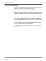
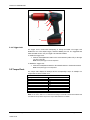
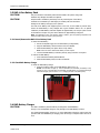
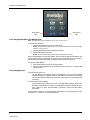
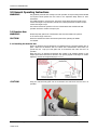
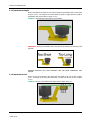
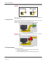
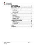
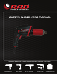
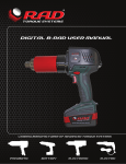
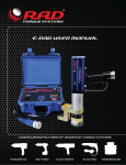
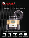
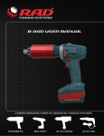
B-RAD USER MANUAL LEADING MANUFACTURER OF ADVANCED TORQUE SYSTEMS PNEUMATIC BATTERY ELECTRONIC ELECTRIC B-RAD 2.5 USER MANUAL TABLE OF CONTENTS TABLE OF CONTENTS ..................................................................... 1 MANUAL REVISION HISTORY ........................................................ 2 IMPORTANT SAFETY NOTICE ......................................................... 3 1.0 General Information ................................................................ 5 1.1 System Components ................................................................... 5 1.2 Specifications ............................................................................. 5 1.2.1 1.2.2 1.2.3 1.2.4 Torque Ranges .......................................................................................... 5 Battery Specifications ................................................................................. 6 Environmental Specifications ...................................................................... 6 Cycle of Operation ..................................................................................... 6 2.0 Tool System ............................................................................. 6 2.1 Tool Handle ............................................................................... 6 2.1.1 Trigger Lock .............................................................................................. 7 2.2 Torque Chart.............................................................................. 7 2.3 RAD Li-Ion Battery Pack .............................................................. 8 2.3.1 Insert/Remove the RAD Li-Ion Battery Pack ................................................. 8 2.3.2 Check RAD Battery Charge ......................................................................... 8 2.4 RAD Battery Charger ................................................................... 8 2.4.1 Charging the RAD Li-Ion Battery Pack ......................................................... 9 2.4.2 Charging Errors ......................................................................................... 9 3.0 General Operating Instructions ............................................. 10 3.1 Reaction Arm ........................................................................... 10 3.1.1 3.1.2 3.1.3 3.1.4 Installing the Reaction Arm ...................................................................... 10 Reaction Arm Height ................................................................................ 11 Reaction Arm Foot ................................................................................... 11 Reaction Points ....................................................................................... 12 3.2 Torque Operation ..................................................................... 12 4.0 Error....................................................................................... 13 5.0 Contact Us ............................................................................. 14 New World Technologies Inc. V2014.07.03 Page • 1 B-RAD 2.5 USER MANUAL MANUAL REVISION HISTORY REVISION: 2014.07.03 New World Technologies Inc. V2014.07.03 Page • 2 B-RAD 2.5 USER MANUAL IMPORTANT SAFETY NOTICE RAD TOOLS ARE SAFE AND RELIABLE. NOT FOLLOWING PRECAUTIONS AND INSTRUCTIONS OUTLINED HERE CAN RESULT IN INJURY TO THE TOOL, OPERATOR AND FELLOW WORKERS. NEW WORLD TECHNOLOGIES INCORPRATED IS NOT RESPONSIBLE FOR ANY SUCH INJURY. B-RAD Tool System Safety The intended use of the B-RAD Tool System is for commercial and industrial bolting applications. Do not operate the B-RAD Tool System before reading and understanding this user manual and noting the Safety Notices displayed on the B-RAD Tool System and throughout this manual. Only qualified personnel with training in the safe operation of torque tooling and the B-RAD Tool System should attempt the installation, operation and diagnosis of the B-RAD Tool System. The B-RAD Tool System is connected to high voltage power and consists of external rotating parts. Improper training and use can cause serious or fatal injury. Do not disassemble or attempt to repair the B-RAD Tool System; doing so will void warranty. If breakdown, malfunction or damage occurs and the B-RAD Tool System fails to operate correctly, contact New World Technologies Inc. Technical Support (refer to Section 5.0 – Contact Us). The B-RAD Tool System should only be used if environmental storage and operation specifications have been met. Refer to Section 1.2.3 – Environmental Specifications. Do not operate the B-RAD Tool System in explosive atmospheres, including, but not limited to, the presence of flammable liquids, gases or dust. The B-RAD Tool System creates sparks which could ignite these substances. Do not expose the B-RAD Tool System to wet conditions. Water in the B-RAD Tool System will cause damage to the tool and increase the risk of electric shock. After long durations of use, the B-RAD Tool System will become hot. It is recommended to use the tool in short intervals and allow for cooling between uses to prevent injury to the operator or damage to the B-RAD Tool System. While operating the B-RAD Tool System, always wear safety goggles and keep all body parts clear of moving parts and the reaction arm contact point. Never exceed the Maximum Torque of the B-RAD Tool System. Failure to comply will result in void warranty. The B-RAD Tool System has been calibrated by a qualified Calibration Technician; calibration must be done by a qualified Calibration Technician. Improper calibration can cause damage to the tool and joint. New World Technologies Inc. V2014.07.03 Page • 3 B-RAD 2.5 USER MANUAL RAD Li-Ion Battery Pack Safety Only use the RAD Li-Ion Battery Pack with the B-RAD Tool System. The use of other batteries with the B-RAD Tool System will cause damage to the tool. The RAD Li-Ion Battery Pack should only be charged on the RAD Battery Charger. If an incompatible charger is used, damage to the RAD Battery will occur. Keep the RAD Li-Ion Battery Pack away from any metal objects. If the battery terminals are connected by a metal object, the battery will short and will cause damage to the battery and injury to the operator. Do not expose the RAD Li-Ion Battery Pack to wet conditions. This will cause damage to the RAD Battery and increase the risk of electric shock. Do not use faulty or deformed RAD Batteries. Do not attempt to open the RAD Battery. Do not short circuit the RAD Battery. Failure to comply will cause damage to the RAD Battery and injury to the operator. If liquid is ejected from the RAD Battery, avoid contact. If contact occurs, immediately flush with water. If contact with eyes occurs, immediately flush with water and seek medical aid. Liquid from the RAD Battery may cause irritation and/or burns. RAD Li-Ion Battery Packs cannot be disposed of with regular waste. Return RAD Batteries to your RAD Distributor. New World Technologies Inc. V2014.07.03 Page • 4 B-RAD 2.5 USER MANUAL 1.0 General Information 1.1 System Components The B-RAD Tool System is shipped from New World Technologies Inc. in a case with the following parts: - B-RAD Tool (Figure 1.1-1) Two RAD Li-Ion Battery Packs (Figure 1.1-2) RAD Battery Charger (Figure 1.1-3) Standard Reaction Arm and Snap Ring (Figure 1.1-4) Calibration Certificate User Manual Figure 1.1-1: B-RAD Tool Figure 1.1-2: RAD Li-Ion Battery Pack Figure 1.1-3: RAD Battery Charger Figure 1.1-4: Standard Reaction Arm Note: Some distributors may ship additional parts along with the B-RAD Tool System. 1.2 Specifications 1.2.1 Torque Ranges The following table outlines the torque ranges, in Foot-Pounds and Newton-Meters, of each B-RAD Tool System: Imperial B-RAD 500 100-500 FtLb B-RAD 500-2 B-RAD 1000 300-1000 FtLb B-RAD 1000-2 B-RAD 1500 500-1500 FtLb B-RAD 1500-2 Table 1.2.1: Torque Ranges New World Technologies Inc. V2014.07.03 Metric or or or or or or B-RAD B-RAD B-RAD B-RAD B-RAD B-RAD 675 675-2 1350 1350-2 2000 2000-2 135-675 Nm 400-1350 Nm 675-2000 Nm Page • 5 B-RAD 2.5 USER MANUAL 1.2.2 Battery Specifications Ensure that all Battery Specifications are followed when utilizing the B-RAD Tool System. Battery Output Voltage Current 18 VDC 30 A 60 minutes Input Output 115 VAC 12 – 18 VDC 2.5 A Charge Time Charger Voltage Charger Output Current Table 1.2.2: Battery Specifications 1.2.3 Environmental Specifications CAUTION! Only operate the B-RAD Tool System if the following environmental storage and operation specifications have been met. Temperature Ranges Operating Temperature Charging Temperature Storage Temperature Humidity Shock Vibration Required Operating Conditions ̊C ̊F 0 – 35 32 – 95 0 – 50 32 – 122 -25 – 70 -13 – 158 10% to 90% non-condensing 10G according to DIN IEC 68-2-6/29 1G, 10-150Hz according to DIN IEC 68-2-6/29 Non explosive atmosphere Dry location Table 1.2.3: Environmental Specifications 1.2.4 Cycle of Operation 5 second forward 10 second rest and switch to reverse mode 5 second reverse mode 20 second rest and switch to forward mode 2.0 Tool System The following sections give a visual and functional description of the Tool Handle, RAD LiIon Battery Pack and RAD Battery Charger. 2.1 Tool Handle The B-RAD (Figure 2.1-1) is trigger activated with a Forward/Reverse Switch. The RAD LiIon Battery Pack is attached to the bottom of the Tool Handle. New World Technologies Inc. V2014.07.03 1. On/Off Trigger – tool activation 2. Forward/Reverse Switch – controls direction of rotation 3. Torque Chart – Settings and corresponding Torque reference 4. Setting Dial – controls Output Torque 5. High(2)/Low(1) Switch – always in the High(2) Position 6. RAD Li-Ion Battery Pack – refer to Section 2.2 – RAD Li-Ion Battery Pack 7. Battery Release Button – refer to Section 2.2.1 – Insert/Remove the RAD Li-Ion Battery Pack Page • 6 B-RAD 2.5 USER MANUAL 4 5 2 3 1 7 6 Figure 2.1-1: B-RAD 2.1.1 Trigger Lock The Trigger Lock is useful while transporting or storing the B-RAD. The Trigger Lock disables the use of the On/Off Trigger, therefore disabling the tool. It is suggested that while the B-RAD is not in use, the Trigger Lock should be enabled. To enable the Trigger Lock: 1. Slide the Forward/Reverse Switch to the Centre Position (neither fully to the right nor fully to the left). Note: The On/Off Trigger cannot be depressed. To disable the Trigger Lock: 1. Slide the Forward/Reverse Switch to the Forward Position or the Reverse Position. Note: The On/Off Trigger can be depressed. 2.2 Torque Chart The Torque Chart displays the Settings and the corresponding Torque. An example of a Torque Chart is shown in Table 2.2-1. B-RAD 700-2 Torque Chart Setting 1 2 3 4 5 6 7 8 Cal. Date: 01/01/2010 Table 2.2-1: Torque Chart FtLbs Torque 0 234 319 401 503 596 681 818 Serial # B0000 Note: Do not refer to Table 2.2-1 to determine the Setting for the B-RAD. Each B-RAD is different and has a different Torque Chart. Only use the Torque Chart attached to the B-RAD. New World Technologies Inc. V2014.07.03 Page • 7 B-RAD 2.5 USER MANUAL 2.3 RAD Li-Ion Battery Pack CAUTION! Only use the RAD Li-Ion Battery Pack with the B-RAD Tool System. Using other batteries may damage the B-RAD Tool System. CAUTION! Keep the RAD Li-Ion Battery Pack away from any metal objects. If the battery terminals are connected by a metal object, the battery will short and cause damage to the battery and injury to the operator. The RAD Li-Ion Battery Pack supplies power to the tool; for the B-RAD to preform best, ensure the RAD Battery is fully charged and in good condition before use. In optimal conditions, the RAD Battery should be capable of approximately 100 Torque Cycles at 50% of the Maximum Torque on a joint with a hardness of approximately 10 degrees. Note: The application torque, joint hardness, battery condition, age and operating temperature will affect the actual number of Torque Cycles per charge. 2.3.1 Insert/Remove the RAD Li-Ion Battery Pack To insert the RAD Battery: 1. Ensure the On/Off Trigger is in the Off Position (not depressed). 2. Align the RAD Battery with the bottom of the Tool Handle. 3. Slide the RAD Battery into place until it is fully seated. Note: A click will confirm that the RAD Battery is locked in place. 4. Test that the RAD Battery is locked in place by trying to slide it out of place. To remove the RAD Battery: 1. Press and hold the Battery Release Button. 2. Slide the RAD Battery away from the Tool Handle. 2.3.2 Check RAD Battery Charge To check the RAD Battery Charge: 1. Press the “Charge” button on the RAD Battery (Figure 2.3.2-1). Result: The Red Bars will light up. If all the Red Bars are illuminated, the Battery is fully charged. If none of the Red Bars are illuminated, the RAD Battery is completely discharged and needs charging (refer to Section 2.4.1 – Charging the RAD Li-Ion Battery Pack). “Charge” Button Figure 2.3.2-1: RAD Li-Ion Battery Pack 2.4 RAD Battery Charger CAUTION! The RAD Li-Ion Battery Pack should only be charged on the RAD Battery Charger. If an incompatible charger is used, damage to the RAD Battery will occur. The Charging Status Display (Figure 2.4-1) on the RAD Battery Charger is used to notify the operator when the RAD Battery is charging, when the charge is complete and if there is an error. New World Technologies Inc. V2014.07.03 Page • 8 B-RAD 2.5 USER MANUAL Green Status Light Red Warning Light Figure 2.4-1: Charging Status Display 2.4.1 Charging the RAD Li-Ion Battery Pack Note: The temperature range for charging is 0˚C to 50˚C (32 ̊ F to 122 ̊ F). To charge the RAD Battery: 1. Plug the RAD Battery Charger into the wall outlet. Result: The Red Warning Light will turn on for one second and then the Green Status Light will turn on for one second. 2. Align the RAD Battery with the RAD Battery Charger. 3. Slide the RAD Battery into place. Result: The Green Status Light will flash while the RAD Battery is charging. When the RAD Battery has been fully charged, the Green Status Light will stop flashing and stay illuminated. Until the RAD Battery is removed from the RAD Charger, it will convert to conservation mode which will maintain the battery charge at maximum capacity. To remove the RAD Battery: 1. Slide the RAD Battery away from the RAD Charger. 2. Check that the RAD Battery is fully charged (refer to Section 2.3.2 – Checking RAD Battery Charge). 2.4.2 Charging Errors The Red Warning Light is on: The RAD Battery is not charging because its temperature is not within the required temperature range for charging. When the RAD Battery’s temperature moves within the required range for charging, the Red Warning Light will turn off and charging will commence. The Red Warning Light is flashing: The RAD Battery may be placed incorrectly on the RAD Battery Charger. Remove the RAD Battery and replace it correctly on the RAD Battery Charger. If the Red Warning Light continues to flash, the RAD Battery is defective; remove the RAD Battery immediately. If these problems continue, contact New World Technologies Inc. Technical Support (refer to Section 5.0 – Contact Us) or your RAD Distributor. New World Technologies Inc. V2014.07.03 Page • 9 B-RAD 2.5 USER MANUAL 3.0 General Operating Instructions WARNING! Only qualified personnel with training in the safe operation of torque tooling and the B-RAD Tool System should operate this tool. Refer to the Important Safety Notice for more information. The B-RAD operates in Torque Cycles. The Torque Cycle passes when the Actual Torque reaches the Target Torque and the Cycle fails if it is interrupted before the Actual Torque reaches the Target Torque. This section instructs the operator in the use of the Reaction Arm needed for B-RAD operation and how to conduct a Torque Cycle. 3.1 Reaction Arm WARNING! Always keep body parts clear of the Reaction Arm when the B-RAD Tool System is in use. Serious injury could occur. CAUTION! Ensure the Reaction Arm has a solid contact point before operating the B-RAD Tool System. 3.1.1 Installing the Reaction Arm Ensure the Reaction Arm and Snap Ring are installed securely to hold the Reaction Arm in place. Make sure the Reaction Arm is in contact with a solid Reaction Point before you operate the tool. Keep your body parts clear of the Reaction Arm when the tool is in operation. When the tool is in operation the Reaction Arm rotates in the opposite direction to the Output Square Drive and must be allowed to rest squarely against a solid object or surface adjacent to the bolt to be tightened (Figure 3.1.1-1). Figure 3.1.1-1 – Reaction Arm Rotation CAUTION! Keep your hand and body parts clear of the Reaction Arm and barrel when the tool is in operation. Figure 3.1.1-2: Incorrect Placement of Hand/Body Parts During Operation New World Technologies Inc. V2014.07.03 Page • 10 B-RAD 2.5 USER MANUAL 3.1.2 Reaction Arm Height Ensure the height of the socket is even with the height of the Reaction Arm as seen below in Figure 3.1.2-1. The height of the socket cannot be shorter or higher than the height of the Reaction Arm as seen below in Figure 3.1.2-2. CORRECT: The Reaction Arm and socket are even height. Figure 3.1.2-1: Correct Height INCORRECT: The leg of the Reaction Arm is too short on the left side, and too long on the right side. Figure 3.1.2-2: Incorrect Height IMPROPER REACTION WILL VOID WARRANTY AND CAN CAUSE PREMATURE TOOL FAILURE. 3.1.3 Reaction Arm Foot Ensure the foot of the Reaction Arm aligns with the length of the nut as seen in Figure 3.1.3-1. The length of the foot cannot be shorter or longer than the nut as seen in Figure 3.1.3-2. CORRECT: The foot of the Reaction Arm aligns with the length of the nut. Figure 3.1.3-1: Correct Length New World Technologies Inc. V2014.07.03 Page • 11 B-RAD 2.5 USER MANUAL INCORRECT: The foot of the Reaction Arm is too short on the left side, and too long on the right side. Figure 3.1.3-2: Incorrect Length Please contact New World Technologies Inc or your local RAD Authorized Distributor for custom Reaction Arms. 3.1.4 Reaction Points Ensure the Reaction Arm reacts off the middle of the foot as seen in Figure 3.1.4-1. Do not react off the heel of the reaction foot as seen in Figure 3.1.4-2. CORRECT: Reaction Arm is reacting off the middle of the Reaction Arm’s foot. Figure 3.1.4-1: Correct Reaction Point INCORRECT: Reaction Arm is reacting off the heel of the Reaction Arm. This can cause premature tool failure. Figure 3.1.4-2: Incorrect Reaction Point 3.2 Torque Operation To operate the Torque Cycle: New World Technologies Inc. V2014.07.03 1. Refer to the Torque Chart to determine the desired Torque and Setting. 2. Change the Setting Dial (Figure 3.2-1). 3. Ensure the High(2)/Low(1) Switch is in the High(2) Position (Figure 3.2-2). Page • 12 B-RAD 2.5 USER MANUAL Figure 3.2-1: Setting Dial Figure 3.2-2: High(2)/Low(1) Switch 4. Place the B-RAD on the joint system. 5. Ensure the Forward/Reverse Switch is in the Forward Position. 6. Press and hold the On/Off Trigger. Note: To stop the Torque Cycle at any time, release the On/Off Trigger. 7. CAUTION! When the B-RAD reaches the Torque, the clutch mechanism will slip. Immediately release the On/Off Trigger. Damage will occur if the clutch is allowed to slip for extended periods of time. 4.0 Error Important! Disassembling or attempting repair will void warranty. If breakdown, malfunction, or error occurs, contact New World Technologies Inc. Technical Support (refer to Section 5.0 – Contact Us). New World Technologies Inc. V2014.07.03 Page • 13 B-RAD Limited Warranty New Tool Warranty Any new tool branded with the RAD name and purchased from New World Technologies Inc., or through one of its authorized distributors or agents, is warranted to the original purchaser against defects in materials and workmanship for a period of one (1) year from the date of original calibration. Electric drive components such as electric motors, switches, and batteries etc., are covered for a period of three (3) months from the date of original calibration. Under the terms of this warranty, New World Technologies Inc., at its option and F.O.B. either its factory or an authorized service center, will replace or repair for the original purchaser, free of charge, any part or parts, found upon examination by New World Technologies Inc., to be defective in material or workmanship or both. If any product or part is replaced or repaired under the terms of this warranty, that product or part will carry the remainder of the warranty from the date of original calibration. Repaired Tool Warranty Once a tool is beyond its new tool warranty, New World Technologies Inc., for a period of three (3) months from the date of repair, will replace or repair for the original purchaser, free of charge, any part or parts, found upon examination by New World Technologies Inc., to be defective in material or workmanship or both. If any product or part is replaced or repaired under the terms and conditions of this warranty, that product or part will carry the remainder of the warranty from the date of original repair. To qualify for the above mentioned warranties, written notice to New World Technologies Inc. must be given immediately upon discovery of such defect, at which time New World Technologies Inc. will issue an authorization to return the tool. The defective item must promptly be returned to New World Technologies Inc. all freight charges prepaid. When returning a tool, the reaction arm/s being used with the tool must also be returned. New World Technologies Inc.: Telephone: 1 800 983 0044 Email: [email protected] Exclusions from Warranty At New World Technologies Inc.'s sole judgment tools or accessories that have been altered, damaged, misused, abused, badly worn due to excessive utilization, lost, or improperly maintained will NOT be covered under the terms of this warranty. Tools returned without the reaction arm/s will not be covered under the terms of this warranty. Consumable parts and accessories (such as extensions, reaction blanks/arms) are not covered under this warranty. Tools that have been relabeled without prior written consent of New World Technologies Inc. will not be covered under this warranty. Equipment and accessories not manufactured by New World Technologies Inc. (measuring equipment, etc.) are warranted only to the extent of the original manufacturer's warranty. *There is no other express warranty. Implied warranties, including those of merchantability and fitness for a particular purpose are limited to one year from date of calibration and to the extent permitted by law. Liability for consequential damages under any and all warranties are excluded to the extent exclusion is permitted by law.