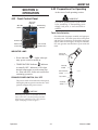
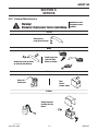
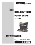
1
15C
AIRCUT
™
PLASMA CUTTING SYSTEM
WITH BUILT IN AIR COMPRESSOR
Art # A-08746
Operating Manual
Rev. AD
Operating Features:
Date: March 24, 2011 PLASMA
Manual # 0-4965
WE APPRECIATE YOUR BUSINESS!
Congratulations on your new Thermal Dynamics product. We are
proud to have you as our customer and will strive to provide you
with the best service and reliability in the industry. This product is
backed by our extensive warranty and world-wide service network.
To locate your nearest distributor or service agency call 1-800-4261888, or visit us on the web at www.thermadyne.com.
This Operating Manual has been designed to instruct you on the
correct use and operation of your Thermal Dynamics product. Your
satisfaction with this product and its safe operation is our ultimate
concern. Therefore please take the time to read the entire manual,
especially the Safety Precautions. They will help you to avoid potential hazards that may exist when working with this product.
YOU ARE IN GOOD COMPANY!
The Brand of Choice for Contractors and Fabricators Worldwide.
Thermal Dynamics is a Global Brand of manual and automation
Plasma Cutting Products for Thermadyne Industries Inc.
We distinguish ourselves from our competition through marketleading, dependable products that have stood the test of time.
We pride ourselves on technical innovation, competitive prices,
excellent delivery, superior customer service and technical support,
together with excellence in sales and marketing expertise.
Above all, we are committed to developing technologically advanced products to achieve a safer working environment within
the welding industry.
!
WARNING
Read and understand this entire Manual and your employer’s safety practices before installing, operating, or servicing the equipment.
While the information contained in this Manual represents the Manufacturer's best judgement, the Manufacturer assumes no liability for its use.
Plasma Cutting Power Supply, 15C AirCut™
PCH 10 Torch
Operating Manual No. 0-4965
Published by:
Thermadyne Corporation
82 Benning Street
West Lebanon, New Hampshire, USA 03784
(603) 298-5711
www.thermadyne.com
© Copyright 2008, 2009, 2010, 2011 by
Thermadyne Corporation
All rights reserved.
Reproduction of this work, in whole or in part, without written permission
of the publisher is prohibited.
The publisher does not assume and hereby disclaims any liability to any
party for any loss or damage caused by any error or omission in this
Manual, whether such error results from negligence, accident, or any
other cause.
Printed in the United States of America
Original Publication Date: January 2, 2008
Revision Date: March 24, 2011
Record the following information for Warranty purposes:
Where Purchased: ___________________________________
Purchase Date:______________________________________
Power Supply Serial #:_______________________________
Torch Serial #:_____________________________________
i
Intentionally blank
TABLE OF CONTENTS
SECTION 1:GENERAL INFORMATION....................................................................................1-1
1.01
1.02
1.03
1.04
1.05
1.06
1.07
1.08
Notes, Cautions and Warnings....................................................................1-1
Important Safety Precautions......................................................................1-1
Publications.................................................................................................1-2
Note, Attention et Avertissement.................................................................1-3
Precautions De Securite Importantes..........................................................1-3
Documents De Reference............................................................................1-5
Declaration of Conformity............................................................................1-6
Statement of Warranty.................................................................................1-7
SECTION 2:INTRODUCTION ..................................................................................................2-1
2.01
2.02
2.03
2.04
2.05
2.06
2.07
2.08
2.09
How To Use This Manual.............................................................................2-1
Equipment Identification..............................................................................2-1
Receipt Of Equipment..................................................................................2-1
Introduction..................................................................................................2-1
General Specification...................................................................................2-2
Features.......................................................................................................2-2
Torch Specifications.....................................................................................2-3
System Contents.........................................................................................2-3
Transporting Methods..................................................................................2-3
SECTION 3:INSTALLATION......................................................................................................3-1
3.01
3.02
3.03
Site Selection...............................................................................................3-1
Electrical Input Connections........................................................................3-1
Torch............................................................................................................3-1
SECTION 4: OPERATION.........................................................................................................4-1
4.01
4.02
Front Control Panel......................................................................................4-1
Preparations For Operating.........................................................................4-1
SECTION 5:SERVICE...............................................................................................................5-1
5.01
5.02
General Maintenance..................................................................................5-1
Basic Troubleshooting Guide.......................................................................5-2
SECTION 6:PARTS LISTS........................................................................................................6-1
6.01
6.02
6.03
Introduction..................................................................................................6-1
Ordering Information....................................................................................6-1
Power Supply Replacement Parts...............................................................6-1
Appendix 1: Operating Sequence, Block Diagram................................................................... A-1
Appendix 2: Torch Connection................................................................................................. A-2
Appendix 3: System Schematic 120V .................................................................................... A-4
GLOBAL CUSTOMER SERVICE CONTACT INFORMATION.......................... Inside Rear Cover
TABLE OF CONTENTS
This Page Intentionally Blank
AIRcut 15C
SECTION 1:
GENERAL INFORMATION
• The kinds of fumes and gases from the plasma arc depend on
the kind of metal being used, coatings on the metal, and the
different processes. You must be very careful when cutting
or welding any metals which may contain one or more of the
following:
1.01 Notes, Cautions and Warnings
Throughout this manual, notes, cautions, and warnings are used to
highlight important information. These highlights are categorized as
follows:
Chromium
Cobalt
Copper
Lead
Manganese
Mercury
Nickel
Selenium
Silver
Vanadium
• Always read the Material Safety Data Sheets (MSDS) that should
be supplied with the material you are using. These MSDSs
will give you the information regarding the kind and amount of
fumes and gases that may be dangerous to your health.
NOTE
An operation, procedure, or background information
which requires additional emphasis or is helpful in efficient operation of the system.
• For information on how to test for fumes and gases in your
workplace, refer to item 1 in Subsection 1.03, Publications in
this manual.
CAUTION
• Use special equipment, such as water or down draft cutting
tables, to capture fumes and gases.
A procedure which, if not properly followed, may cause
damage to the equipment.
!
Antimony
Arsenic
Barium
Beryllium
Cadmium
• Do not use the plasma torch in an area where combustible or
explosive gases or materials are located.
• Phosgene, a toxic gas, is generated from the vapors of chlorinated solvents and cleansers. Remove all sources of these
vapors.
WARNING
• This product, when used for welding or cutting, produces
fumes or gases which contain chemicals known to the State
of California to cause birth defects and, in some cases, cancer.
(California Health & Safety Code Sec. 25249.5 et seq.)
A procedure which, if not properly followed, may cause
injury to the operator or others in the operating area.
1.02 Important Safety Precautions
ELECTRIC SHOCK
WARNINGS
OPERATION AND MAINTENANCE OF PLASMA ARC
EQUIPMENT CAN BE DANGEROUS AND HAZARDOUS
TO YOUR HEALTH.
Electric Shock can injure or kill. The plasma arc process uses and
produces high voltage electrical energy. This electric energy can cause
severe or fatal shock to the operator or others in the workplace.
• Never touch any parts that are electrically “live” or “hot.”
Plasma arc cutting produces intense electric and
magnetic emissions that may interfere with the proper
function of cardiac pacemakers, hearing aids, or other
electronic health equipment. Persons who work near
plasma arc cutting applications should consult their
medical health professional and the manufacturer of
the health equipment to determine whether a hazard
exists.
• Wear dry gloves and clothing. Insulate yourself from the work
piece or other parts of the welding circuit.
• Repair or replace all worn or damaged parts.
• Extra care must be taken when the workplace is moist or
damp.
• Install and maintain equipment according to NEC code, refer
to item 9 in Subsection 1.03, Publications.
To prevent possible injury, read, understand and follow
all warnings, safety precautions and instructions before
using the equipment. Call 1-603-298-5711 or your local
distributor if you have any questions.
GASES AND FUMES
Gases and fumes produced during the plasma cutting process can be
dangerous and hazardous to your health.
• Disconnect power source before performing any service or
repairs.
• Read and follow all the instructions in the Operating Manual.
Fire AND EXPLOSION
Fire and explosion can be caused by hot slag, sparks, or the plasma
arc.
• Keep all fumes and gases from the breathing area. Keep your
head out of the welding fume plume.
• Be sure there is no combustible or flammable material in the
workplace. Any material that cannot be removed must be
protected.
• Use an air-supplied respirator if ventilation is not adequate to
remove all fumes and gases.
• Ventilate all flammable or explosive vapors from the workplace.
Manual 0-4961 1-1
GENERAL INFORMATION
aircut 15c
1.03 Publications
• Do not cut or weld on containers that may have held combustibles.
• Provide a fire watch when working in an area where fire hazards
may exist.
Refer to the following standards or their latest revisions for more
information:
• Hydrogen gas may be formed and trapped under aluminum
workpieces when they are cut underwater or while using a water
table. DO NOT cut aluminum alloys underwater or on a water
table unless the hydrogen gas can be eliminated or dissipated.
Trapped hydrogen gas that is ignited will cause an explosion.
1. OSHA, SAFETY AND HEALTH STANDARDS, 29CFR 1910,
obtainable from the Superintendent of Documents, U.S.
Government Printing Office, Washington, D.C. 20402
2. ANSI Standard Z49.1, SAFETY IN WELDING AND CUTTING,
obtainable from the American Welding Society, 550 N.W.
LeJeune Rd, Miami, FL 33126
3. NIOSH, SAFETY AND HEALTH IN ARC WELDING AND GAS
WELDING AND CUTTING, obtainable from the Superintendent
of Documents, U.S. Government Printing Office, Washington,
D.C. 20402
NOISE
Noise can cause permanent hearing loss. Plasma arc processes can
cause noise levels to exceed safe limits. You must protect your ears
from loud noise to prevent permanent loss of hearing.
4. ANSI Standard Z87.1, SAFE PRACTICES FOR OCCUPATION
AND EDUCATIONAL EYE AND FACE PROTECTION, obtainable
from American National Standards Institute, 1430 Broadway,
New York, NY 10018
• To protect your hearing from loud noise, wear protective ear
plugs and/or ear muffs. Protect others in the workplace.
• Noise levels should be measured to be sure the decibels (sound)
do not exceed safe levels.
5. ANSI Standard Z41.1, STANDARD FOR MEN’S SAFETY-TOE
FOOTWEAR, obtainable from the American National Standards
Institute, 1430 Broadway, New York, NY 10018
• For information on how to test for noise, see item 1 in Subsection 1.03, Publications, in this manual.
6. ANSI Standard Z49.2, FIRE PREVENTION IN THE USE OF CUTTING AND WELDING PROCESSES, obtainable from American
National Standards Institute, 1430 Broadway, New York, NY
10018
PLASMA ARC RAYS
Plasma Arc Rays can injure your eyes and burn your skin. The plasma
arc process produces very bright ultra violet and infra red light. These
arc rays will damage your eyes and burn your skin if you are not
properly protected.
7. AWS Standard A6.0, WELDING AND CUTTING CONTAINERS WHICH HAVE HELD COMBUSTIBLES, obtainable from
American Welding Society, 550 N.W. LeJeune Rd, Miami, FL
33126
• To protect your eyes, always wear a welding helmet or shield.
Also always wear safety glasses with side shields, goggles or
other protective eye wear.
8. NFPA Standard 51, OXYGEN-FUEL GAS SYSTEMS FOR
WELDING, CUTTING AND ALLIED PROCESSES, obtainable
from the National Fire Protection Association, Batterymarch
Park, Quincy, MA 02269
• Wear welding gloves and suitable clothing to protect your skin
from the arc rays and sparks.
9. NFPA Standard 70, NATIONAL ELECTRICAL CODE, obtainable
from the National Fire Protection Association, Batterymarch
Park, Quincy, MA 02269
• Keep helmet and safety glasses in good condition. Replace
lenses when cracked, chipped or dirty.
10.NFPA Standard 51B, CUTTING AND WELDING PROCESSES,
obtainable from the National Fire Protection Association,
Batterymarch Park, Quincy, MA 02269
• Protect others in the work area from the arc rays. Use protective
booths, screens or shields.
• Use the shade of lens as suggested in the following per ANSI/
ASC Z49.1:
Arc Current
Minimum Protective
Shade No.
Suggested
Shade No.
Less Than 300*
8
9
300 - 400*
9
12
400 - 800*
10
14
11.CGA Pamphlet P-1, SAFE HANDLING OF COMPRESSED
GASES IN CYLINDERS, obtainable from the Compressed
Gas Association, 1235 Jefferson Davis Highway, Suite 501,
Arlington, VA 22202
12.CSA Standard W117.2, CODE FOR SAFETY IN WELDING
AND CUTTING, obtainable from the Canadian Standards Association, Standards Sales, 178 Rexdale Boulevard, Rexdale,
Ontario, Canada M9W 1R3
13.NWSA booklet, WELDING SAFETY BIBLIOGRAPHY obtainable
from the National Welding Supply Association, 1900 Arch
Street, Philadelphia, PA 19103
* These values apply where the actual arc is clearly seen.
Experience has shown that lighter filters may be used
when the arc is hidden by the workpiece.
14.American Welding Society Standard AWSF4.1, RECOMMENDED SAFE PRACTICES FOR THE PREPARATION FOR
WELDING AND CUTTING OF CONTAINERS AND PIPING THAT
HAVE HELD HAZARDOUS SUBSTANCES, obtainable from the
American Welding Society, 550 N.W. LeJeune Rd, Miami, FL
33126
LEAD WARNING
This product contains chemicals, including lead, or otherwise produces
chemicals known to the State of California to cause cancer, birth defects
and other reproductive harm. Wash hands after handling. (California
15.ANSI Standard Z88.2, PRACTICE FOR RESPIRATORY PROTECTION, obtainable from American National Standards
Institute, 1430 Broadway, New York, NY 10018
Health & Safety Code § 25249.5 et seq.).
GENERAL INFORMATION
1-2
Manual 0-4961
AIRcut 15C
1.04 Note, Attention et Avertissement
•
Les sortes de gaz et de fumée provenant de l’arc de plasma dépendent du genre de métal utilisé, des revêtements se trouvant sur le
métal et des différents procédés. Vous devez prendre soin lorsque
vous coupez ou soudez tout métal pouvant contenir un ou plusieurs
des éléments suivants:
antimoine
argent
arsenic
baryum
béryllium
•
Lisez toujours les fiches de données sur la sécurité des matières
(sigle américain “MSDS”); celles-ci devraient être fournies avec le
matériel que vous utilisez. Les MSDS contiennent des renseignements quant à la quantité et la nature de la fumée et des gaz pouvant
poser des dangers de santé.
•
Pour des informations sur la manière de tester la fumée et les gaz
de votre lieu de travail, consultez l’article 1 et les documents cités
à la page 5.
•
Utilisez un équipement spécial tel que des tables de coupe à débit
d’eau ou à courant descendant pour capter la fumée et les gaz.
•
N’utilisez pas le chalumeau au jet de plasma dans une zone où se
trouvent des matières ou des gaz combustibles ou explosifs.
•
Le phosgène, un gaz toxique, est généré par la fumée provenant
des solvants et des produits de nettoyage chlorés. Eliminez toute
source de telle fumée.
•
Ce produit, dans le procéder de soudage et de coupe, produit de
la fumée ou des gaz pouvant contenir des éléments reconnu dans
L’état de la Californie, qui peuvent causer des défauts de naissance
et le cancer. (La sécurité de santé en Californie et la code sécurité
Sec. 25249.5 et seq.)
Dans ce manuel, les mots “note,” “attention,” et “avertissement” sont
utilisés pour mettre en relief des informations à caractère important.
Ces mises en relief sont classifiées comme suit :
NOTE
Toute opération, procédure ou renseignement général
sur lequel il importe d’insister davantage ou qui contribue
à l’efficacité de fonctionnement du système.
ATTENTION
Toute procédure pouvant résulter l’endommagement
du matériel en cas de non-respect de la procédure en
question.
!
AVERTISSEMENT
Toute procédure pouvant provoquer des blessures de
l’opérateur ou des autres personnes se trouvant dans
la zone de travail en cas de non-respect de la procédure
en question.
1.05 Precautions De Securite Importantes
AVERTISSEMENTS
L’OPÉRATION ET LA MAINTENANCE DU MATÉRIEL
DE SOUDAGE À L’ARC AU JET DE PLASMA PEUVENT
PRÉSENTER DES RISQUES ET DES DANGERS DE
SANTÉ.
Coupant à l’arc au jet de plasma produit de l’énergie
électrique haute tension et des émissions magnétique qui
peuvent interférer la fonction propre d’un “pacemaker”
cardiaque, les appareils auditif, ou autre matériel de santé
electronique. Ceux qui travail près d’une application à
l’arc au jet de plasma devrait consulter leur membre professionel de médication et le manufacturier de matériel de
santé pour déterminer s’il existe des risques de santé.
Il faut communiquer aux opérateurs et au personnel
TOUS les dangers possibles. Afin d’éviter les blessures
possibles, lisez, comprenez et suivez tous les avertissements, toutes les précautions de sécurité et toutes les
consignes avant d’utiliser le matériel. Composez le +
603-298-5711 ou votre distributeur local si vous avez
des questions.
FUMÉE et GAZ
cadmiummercure
chrome
cobalt
cuivre
manganèse
nickel
plomb
sélénium
vanadium
CHOC ELECTRIQUE
Les chocs électriques peuvent blesser ou même tuer. Le procédé au jet
de plasma requiert et produit de l’énergie électrique haute tension. Cette
énergie électrique peut produire des chocs graves, voire mortels, pour
l’opérateur et les autres personnes sur le lieu de travail.
•
Ne touchez jamais une pièce “sous tension” ou “vive”; portez des
gants et des vêtements secs. Isolez-vous de la pièce de travail ou
des autres parties du circuit de soudage.
•
Réparez ou remplacez toute pièce usée ou endommagée.
•
Prenez des soins particuliers lorsque la zone de travail est humide
ou moite.
•
Montez et maintenez le matériel conformément au Code électrique
national des Etats-Unis. (Voir la page 5, article 9.)
•
Débranchez l’alimentation électrique avant tout travail d’entretien
ou de réparation.
•
Lisez et respectez toutes les consignes du Manuel de consignes.
La fumée et les gaz produits par le procédé de jet de plasma peuvent
présenter des risques et des dangers de santé.
•
Eloignez toute fumée et gaz de votre zone de respiration. Gardez
votre tête hors de la plume de fumée provenant du chalumeau.
•
Utilisez un appareil respiratoire à alimentation en air si l’aération
fournie ne permet pas d’éliminer la fumée et les gaz.
Manual 0-4961 INCENDIE ET EXPLOSION
Les incendies et les explosions peuvent résulter des scories chaudes,
des étincelles ou de l’arc de plasma. Le procédé à l’arc de plasma
1-3
GENERAL INFORMATION
aircut 15c
produit du métal, des étincelles, des scories chaudes pouvant mettre
le feu aux matières combustibles ou provoquer l’explosion de fumées
inflammables.
BRUIT
•
Soyez certain qu’aucune matière combustible ou inflammable ne
se trouve sur le lieu de travail. Protégez toute telle matière qu’il
est impossible de retirer de la zone de travail.
•
Procurez une bonne aération de toutes les fumées inflammables
ou explosives.
•
Ne coupez pas et ne soudez pas les conteneurs ayant pu renfermer
des matières combustibles.
•
Prévoyez une veille d’incendie lors de tout travail dans une zone
présentant des dangers d’incendie.
•
Le gas hydrogène peut se former ou s’accumuler sous les pièces
de travail en aluminium lorsqu’elles sont coupées sous l’eau ou
sur une table d’eau. NE PAS couper les alliages en aluminium sous
l’eau ou sur une table d’eau à moins que le gas hydrogène peut
s’échapper ou se dissiper. Le gas hydrogène accumulé explosera
si enflammé.
Les rayons provenant de l’arc de plasma peuvent blesser vos yeux et
brûler votre peau. Le procédé à l’arc de plasma produit une lumière
infra-rouge et des rayons ultra-violets très forts. Ces rayons d’arc
nuiront à vos yeux et brûleront votre peau si vous ne vous protégez
pas correctement.
Pour protéger vos yeux, portez toujours un casque ou un écran
de soudeur. Portez toujours des lunettes de sécurité munies de
parois latérales ou des lunettes de protection ou une autre sorte
de protection oculaire.
•
Portez des gants de soudeur et un vêtement protecteur approprié
pour protéger votre peau contre les étincelles et les rayons de
l’arc.
•
Maintenez votre casque et vos lunettes de protection en bon état.
Remplacez toute lentille sale ou comportant fissure ou rognure.
•
Protégez les autres personnes se trouvant sur la zone de travail
contre les rayons de l’arc en fournissant des cabines ou des écrans
de protection.
•
Utilisez la nuance de lentille qui est suggèrée dans le recommendation qui suivent ANSI/ASC Z49.1:
Courant Arc
Nuance Minimum
Protective Numéro
Nuance Suggerée
Numéro
Moins de 300*
8
9
300 - 400*
9
12
400 - 800*
10
14
•
Pour protéger votre ouïe contre les bruits forts, portez des tampons
protecteurs et/ou des protections auriculaires. Protégez également
les autres personnes se trouvant sur le lieu de travail.
•
Il faut mesurer les niveaux sonores afin d’assurer que les décibels
(le bruit) ne dépassent pas les niveaux sûrs.
•
Pour des renseignements sur la manière de tester le bruit, consultez
l’article 1, page 5.
PLOMB AVERTISSEMENT
RAYONS D’ARC DE PLASMA
•
Le bruit peut provoquer une perte permanente de l’ouïe. Les procédés
de soudage à l’arc de plasma peuvent provoquer des niveaux sonores
supérieurs aux limites normalement acceptables. Vous dú4ez vous
protéger les oreilles contre les bruits forts afin d’éviter une perte
permanente de l’ouïe.
Ce produit contient des produits chimiques, comme le plomb,
ou engendre des produits chimiques, reconnus par l’état de
Californie comme pouvant être à l’origine de cancer, de malformations fœtales ou d’autres problèmes de reproduction.
Il faut se laver les mains après toute manipulation.
(Code de Californie de la sécurité et santé, paragraphe 25249.5 et
suivants)
* Ces valeurs s’appliquent ou l’arc actuel est observé
clairement. L’experience a démontrer que les filtres
moins foncés peuvent être utilisés quand l’arc est caché
par moiceau de travail.
GENERAL INFORMATION
1-4
Manual 0-4961
AIRcut 15C
1.06 Documents De Reference
Consultez les normes suivantes ou les révisions les plus récentes ayant
été faites à celles-ci pour de plus amples renseignements :
1. OSHA, NORMES DE SÉCURITÉ DU TRAVAIL ET DE PROTECTION
DE LA SANTÉ, 29CFR 1910, disponible auprès du Superintendent
of Documents, U.S. Government Printing Office, Washington, D.C.
20402
2. Norme ANSI Z49.1, LA SÉCURITÉ DES OPÉRATIONS DE COUPE
ET DE SOUDAGE, disponible auprès de la Société Américaine de
Soudage (American Welding Society), 550 N.W. LeJeune Rd.,
Miami, FL 33126
14. Norme AWSF4.1 de l’Association Américaine de Soudage, RECOMMANDATIONS DE PRATIQUES SURES POUR LA PRÉPARATION À
LA COUPE ET AU SOUDAGE DE CONTENEURS ET TUYAUX AYANT
RENFERMÉ DES PRODUITS DANGEREUX , disponible auprès de
la American Welding Society, 550 N.W. LeJeune Rd., Miami, FL
33126
15. Norme ANSI Z88.2, PRATIQUES DE PROTECTION RESPIRATOIRE,
disponible auprès de l’American National Standards Institute, 1430
Broadway, New York, NY 10018
3. NIOSH, LA SÉCURITÉ ET LA SANTÉ LORS DES OPÉRATIONS DE
COUPE ET DE SOUDAGE À L’ARC ET AU GAZ, disponible auprès
du Superintendent of Documents, U.S. Government Printing Office,
Washington, D.C. 20402
4. Norme ANSI Z87.1, PRATIQUES SURES POUR LA PROTECTION
DES YEUX ET DU VISAGE AU TRAVAIL ET DANS LES ECOLES,
disponible de l’Institut Américain des Normes Nationales (American National Standards Institute), 1430 Broadway, New York, NY
10018
5. Norme ANSI Z41.1, NORMES POUR LES CHAUSSURES PROTECTRICES, disponible auprès de l’American National Standards
Institute, 1430 Broadway, New York, NY 10018
6. Norme ANSI Z49.2, PRÉVENTION DES INCENDIES LORS DE
L’EMPLOI DE PROCÉDÉS DE COUPE ET DE SOUDAGE, disponible
auprès de l’American National Standards Institute, 1430 Broadway,
New York, NY 10018
7. Norme A6.0 de l’Association Américaine du Soudage (AWS), LE
SOUDAGE ET LA COUPE DE CONTENEURS AYANT RENFERMÉ
DES PRODUITS COMBUSTIBLES, disponible auprès de la American
Welding Society, 550 N.W. LeJeune Rd., Miami, FL 33126
8. Norme 51 de l’Association Américaine pour la Protection contre les
Incendies (NFPA), LES SYSTEMES À GAZ AVEC ALIMENTATION
EN OXYGENE POUR LE SOUDAGE, LA COUPE ET LES PROCÉDÉS
ASSOCIÉS, disponible auprès de la National Fire Protection Association, Batterymarch Park, Quincy, MA 02269
9. Norme 70 de la NFPA, CODE ELECTRIQUE NATIONAL, disponible
auprès de la National Fire Protection Association, Batterymarch
Park, Quincy, MA 02269
10. Norme 51B de la NFPA, LES PROCÉDÉS DE COUPE ET DE SOUDAGE, disponible auprès de la National Fire Protection Association,
Batterymarch Park, Quincy, MA 02269
11. Brochure GCA P-1, LA MANIPULATION SANS RISQUE DES GAZ
COMPRIMÉS EN CYLINDRES, disponible auprès de l’Association
des Gaz Comprimés (Compressed Gas Association), 1235 Jefferson
Davis Highway, Suite 501, Arlington, VA 22202
12. Norme CSA W117.2, CODE DE SÉCURITÉ POUR LE SOUDAGE
ET LA COUPE, disponible auprès de l’Association des Normes
Canadiennes, Standards Sales, 178 Rexdale Boulevard, Rexdale,
Ontario, Canada, M9W 1R3
13. Livret NWSA, BIBLIOGRAPHIE SUR LA SÉCURITÉ DU SOUDAGE,
disponible auprès de l’Association Nationale de Fournitures de
Soudage (National Welding Supply Association), 1900 Arch Street,
Philadelphia, PA 19103
Manual 0-4961 1-5
GENERAL INFORMATION
aircut 15c
1.07 Declaration of Conformity
Manufacturer:
Thermal Dynamics Corporation
Address:
82 Benning Street
West Lebanon, New Hampshire 03784
USA
The equipment described in this manual conforms to all applicable aspects and regulations of the ‘Low Voltage Directive’ (European Council Directive
73/23/EEC as amended by Council Directive 93/68/EEC) and to the National legislation for the enforcement of this Directive.
The equipment described in this manual conforms to all applicable aspects and regulations of the "EMC Directive" (European Council Directive 89/336/
EEC) and to the National legislation for the enforcement of this Directive.
Serial numbers are unique with each individual piece of equipment and details description, parts used to manufacture a unit and date of manufacture.
National Standard and Technical Specifications
The product is designed and manufactured to a number of standards and technical requirements. Among them are:
* UL (Underwriters Laboratory) rating 94VO flammability testing for all printed-circuit boards used.
* For environments with increased hazard of electrical shock, Power Supplies bearing the
mark conform to EN50192 when used in conjunction
with hand torches with exposed cutting tips, if equipped with properly installed standoff guides.
* Extensive product design verification is conducted at the manufacturing facility as part of the routine design and manufacturing process. This is to
ensure the product is safe, when used according to instructions in this manual and related industry standards, and performs as specified. Rigorous
testing is incorporated into the manufacturing process to ensure the manufactured product meets or exceeds all design specifications.
Thermal Dynamics has been manufacturing products for more than 30 years, and will continue to achieve excellence in our area of manufacture.
Manufacturers responsible representative:
Steve Ward
Operations Director
Thermadyne Europe
Europa Building
Chorley N Industrial Park
Chorley, Lancashire ,
England PR6 7BX
GENERAL INFORMATION
1-6
Manual 0-4961
AIRcut 15C
1.08 Statement of Warranty
LIMITED WARRANTY: Subject to the terms and conditions established below, Thermal Dynamics® Corporation warrants to the original retail purchaser
that new Thermal Dynamics CUTMASTER™ plasma cutting systems sold after the effective date of this warranty are free of defects in material and
workmanship. Should any failure to conform to this warranty appear within the applicable period stated below, Thermal Dynamics Corporation shall, upon
notification thereof and substantiation that the product has been stored operated and maintained in accordance with Thermal Dynamics’ specifications,
instructions, recommendations and recognized industry practice, correct such defects by suitable repair or replacement.
This warranty is exclusive and in lieu of any warranty of merchantability or fitness for a particular purpose.
Thermal Dynamics will repair or replace, at its discretion, any warranted parts or components that fail due to defects in material or workmanship within the
time periods set out below. Thermal Dynamics Corporation must be notified within 30 days of any failure, at which time Thermal Dynamics Corporation
will provide instructions on the warranty procedures to be implemented.
Thermal Dynamics Corporation will honor warranty claims submitted within the warranty periods listed below. All warranty periods begin on the date of
sale of the product to the original retail customer or 1 year after sale to an authorized Thermal Dynamics Distributor.
LIMITED WARRANTY PERIOD
Product
Power Supply Components
(Parts and Labor)
Torch and Leads
(Parts and Labor)
AirCut™
1 Year
180 days
This warranty does not apply to:
1.
Consumable Parts, such as tips, electrodes, shield cups, o - rings, starter cartridges, gas distributors, fuses, filters.
2.
Equipment that has been modified by an unauthorized party, improperly installed, improperly operated or misused industry standards.
based upon
In the event of a claim under this warranty, the remedies shall be, at the discretion of Thermal Dynamics Corporation:
1.
Repair of the defective product.
2.
Replacement of the defective product.
3.
Reimbursement of reasonable costs of repair when authorized in advance by Thermal Dynamics.
4.
Payment of credit up to the purchase price less reasonable depreciation based on actual use.
These remedies may be authorized by Thermal Dynamics and are FOB West Lebanon, NH or an authorized Thermadyne service station. Product returned
for service is at the owner’s expense and no reimbursement of travel or transportation is authorized.
LIMITATION OF LIABILITY: Thermal Dynamics Corporation shall not under any circumstances be liable for special or consequential damages such
as, but not limited to, damage or loss of purchased or replacement goods or claims of customer of distributors (hereinafter “Purchaser”) for service
interruption. The remedies of the Purchaser set forth herein are exclusive and the liability of Thermal Dynamics with respect to any contract, or anything
done in connection therewith such as the performance or breach thereof, or from the manufacture, sale, delivery, resale, or use of the goods covered
by or furnished by Thermal Dynamics whether arising out of contract, negligence, strict tort, or under any warranty, or otherwise, shall not, except as
expressly provided herein, exceed the price of the goods upon which liability is based.
This warranty becomes invalid if replacement parts or accessories are used which may impair the safety or performance of any Thermal Dynamics
product.
This warranty is invalid if the Thermal Dynamics product is sold by non - authorized persons.
Effective September 4, 2007
Manual 0-4961 1-7
GENERAL INFORMATION
aircut 15c
GENERAL INFORMATION
1-8
Manual 0-4961
AIRcut 15C
SECTION 2:
INTRODUCTION
2.01 How To Use This Manual
This Owner’s Manual applies to just specification or part numbers listed on page i.
To ensure safe operation, read the entire manual,
including the chapter on safety instructions and
warnings.
Throughout this manual, the words WARNING,
CAUTION, and NOTE may appear. Pay particular attention to the information provided under
these headings. These special annotations are
easily recognized as follows:
!
WARNING
A WARNING gives information regarding
possible personal injury.
CAUTION
A CAUTION refers to possible equipment
damage.
NOTE
A NOTE offers helpful information concerning
certain operating procedures.
Additional copies of this manual may be purchased by contacting Thermal Dynamics at the
address and phone number in your area listed in
the inside back cover of this manual. Include the
Owner’s Manual number and equipment identification numbers.
Electronic copies of this manual can also be
downloaded at no charge in Acrobat PDF format
by going to the
Thermadyne web site listed below, clicking on
the Thermal Dynamics brand logo and then on
the Literature link:
http://www.thermadyne.com
Introduction
2.02 Equipment Identification
The unit’s identification number (specification or part number), model, and serial number
usually appear on a data tag attached to the rear
panel. Equipment which does not have a data tag
such as torch and cable assemblies are identified only by the specification or part number
printed on loosely attached card or the shipping
container. Record these numbers on the bottom
of page i for future reference.
2.03 Receipt Of Equipment
When you receive the equipment, check it
against the invoice to make sure it is complete
and inspect the equipment for possible damage
due to shipping. If there is any damage, notify
the carrier immediately to file a claim. Furnish
complete information concerning damage claims
or shipping errors to the location in your area
listed in the inside back cover of this manual.
Include all equipment identification numbers as
described above along with a full description of
the parts in error.
2.04 Introduction
Plasma is a gas which has been heated to an
extremely high temperature and ionized so that
it becomes electrically conductive. The plasma
arc cutting process uses this plasma to transfer
an electrical arc to the workpiece. The metal to
be cut is melted by the heat of the arc and then
blown away.
2-1
Manual 0-4965
AirCut 15C
2.05 General Specification
Model Description
15C AirCut™
Maximum output
15 Amps
Input Voltage & Phase
120V,
Single Phase
Frequency
60Hz
Input power
2.2 kVA
Current Input fuse
U.S. / Canada 20
Amps
No Load Voltage
330V
Load Voltage
86V
Output Current
15 Amps
Post flow time
12 Seconds
Duty cycle @ 104°F /
40° C Ambient
30% @ 15A,
86vdc
Recommended Cutting
Capacity
1/8”
(3.2 mm)
Maximum Cutting
Capacity
1/4”
(6.5 mm)
Dimension (W * D * H)
6.5”x18”x9.5” (165
mm x 457 mm x
241 mm )
Gross Weight
30 lbs. (11.2 kg )
2.06 Features
• COMPACT and LIGHT - Designed for easy
transportation.
• ENERGY EFFICIENCY - Advanced technology reduces power consumption.
• HIGH SPEED RECOMMENDED CUTTING - The constricted plasma arc provides
high speed cutting as well as a good quality
genuine, narrow cut.
• LOW COST WITH COMPRESSED AIR
- The AirCut™ operates on its own compressed air.
• ALL KINDS OF METALS - Useful for
most metals such as stainless steel, aluminum, mild steel, copper and their alloys.
• PILOT ARC IGNITION FROM TORCH
- The Pilot Arc ignites the cutting arc.
• POWERFUL CUTTING PERFORMANCE
- Recommended cutting capacity is 1/8”
(3.2 mm).
• ABLE TO CUT PAINTED MATERIALS
- Pilot Arc ignition allows the AirCut™ to
cut painted materials.
NOTE:
• EXTENDED PARTS LIFE - Consumable
parts life is longer.
Refer to Local and National Codes or local authority having jurisdiction for proper wiring
requirements.
Introduction
2-2
Manual 0-4965
AIRcut 15C
2.08 System Contents
2.07 Torch Specifications
Description
ITEMS
Q’ty
Power source
Model AirCut™
1
Torch Set
PCH-10, with 20’
(6.1 m) leads
1
Accessories &
Consumables
Work Cable
Manual
Torch Electrodes
Torch Tips
1
1
2
3
Input Power
Cable U.S.
16/3 with molded plug
1
2.9 in
(75 mm)
1.1 in (27 mm)
8 in (203 mm)
Art # A-07719
PCH-10 Torch Ratings
Torch Configuration
Torch Head at 70° to
Torch Handle
Torch Leads Length
20 feet / 6.1 m
Duty Cycle
100% @ 10 Amps
Maximum Current
15 Amps, DC,
Straight Polarity
Type of Cooling
Ambient air and gas
stream through torch
Parts-in-Place:
Built-in Switch
in Torch Head
Gas Requirement:
Single Gas, Internal
Compressed Air Only
Plasma Power
Supply Used With:
AirCut™
2.09 Transporting Methods
Lift unit with handle on top of case. Use handcart or similar device of adequate capacity for
transporting over long distances.
WARNINGS
ELECTRIC SHOCK can kill. DO NOT
TOUCH live electrical parts. Disconnect input
power from supply before moving the power
source.
FALLING EQUIPMENT can cause serious
personal injury and equipment damage.
Introduction
2-3
Manual 0-4965
AirCut 15C
This Page Intentionally Blank
Introduction
2-4
Manual 0-4965
AIRcut 15C
SECTION 3:
INSTALLATION
3.03 Torch
• Make sure that the torch cable and torch
switch terminals are connected to front
panel.
3.01 Site Selection
• Place in a clean and dry area.
• Make sure the Work Cable is secured properly to front panel.
• Provide adequate ventilation and fresh air
supply.
• Before activating, turn torch away from
yourself and others.
• Ideal ambient temperature should not exceed 40°C / 104°F. Temperatures exceeding that may diminish cutting capacity or
quality.
DANGER
Do not cut in humid or wet surroundings.
• The cutting machine must be placed on an
even, firm surface.
• Before you maintain or replace torch parts,
wait for the post flow air cycle to stop, then
turn the machine off and disconnect from
input power.
3.02 Electrical Input Connections
• Input voltage is 120V ± 10%, 50/60 Hz
single phase.
• Always use original manufacturers parts.
The use of aftermarket parts could result in
lower parts life and in unsatisfactory cutting results. Any warranty claims would be
waived.
CAUTION
Check your power source for correct voltage
before plugging in or connecting the unit. The
primary power source, fuse/breaker, and any
extension cords used must conform to local
electrical code and the recommended circuit
protection and wiring requirements as specified
in Section 2.
Installation
• Recycle worn parts according to local requirements.
NOTE
Repairs must be done by skilled and qualified
personnel only.
3-1
Manual 0-4965
AirCut 15C
This Page Intentionally
Installation
3-2
Manual 0-4965
AIRcut 15C
SECTION 4:
OPERATION
4.02 Preparations For Operating
At the start of each operating session:
4.01 Front Control Panel
WARNING
AC Power
Indicator
"On / Off"
Switch
Disconnect primary power at the source
before assembling or disassembling power
supply, torch parts, or torch and leads assemblies.
Overheating
Indicator
AirCut 15
Torch Parts Selection
™
Check the torch for proper assembly and appropriate torch parts. The torch parts must correspond
with the type of operation, and with the amperage
output of this Power Supply (15 amps maximum).
Use only genuine manufacturer’s parts with this
torch.
Air Vents
Torch Lead
Connection
Work Lead
Connection
Art # A-08293_AB
INDICATOR LAMP
Torch Head
Assembly
• Power Indicator
- Lights when primary power switch is turned on.
• TEMPERATURE Indicator - Indicator
is normally OFF. Indicator is ON when
internal temperature exceeds normal limits. Shut unit OFF; let the unit cool before
continuing operation.
Electrode,
9-6006
Gas Distributor,
9-6007
A-07723
Tip, 9-6099
PRIMARY POWER SWITCH, ON / OFF
The power switch is located on the front panel.
Placing the primary power switch to the “ON”
position energizes the power source.
Shield Cup,
9-6003
CAUTION
When the power source is overloaded, the switch
turns to the OFF or neutral position automatically. Return completely to the OFF positioin
before attempting to turn ON again.
Operation
4-1
Manual 0-4965
AirCut 15C
5. To shut off the torch simply release the
Torch Trigger. When the trigger is released a gas post-flow will occur. If the
Torch Trigger is pushed during the postflow, the pilot arc will restart immediately
and the cutting arc will restart when the
torch is brought within range of the work
piece.
Connect Work Cable
Make a solid work cable
connection to the workpiece or cutting table
Typical Cutting Speeds
Cutting speeds vary according to torch output,
the type of material being cut, and operator skill.
Speeds shown are typical for this cutting system
using air plasma to cut materials shown.
A-02022
Torch Operation
• Wear gloves and protective goggles.
Material
• Do not place bare hand on work piece.
1. For drag cutting, keep the torch in contact with the work piece.
2. For standoff cutting, hold the torch 1/8
- 3/8 in (3-9 mm) from the work piece as
shown below.
Mild Steel
Material
Thickness
Inches Per
Minute
1/8”
25.0
3/16”
16.0
1/4”
slow speeds
3. With the torch in starting position, press
and hold the Torch Trigger. The pilot arc
will come on and remain on until the cutting arc starts.
4. Once on, the cutting arc remains on as
long as the Torch Trigger is held down.
Operation
4-2
Manual 0-4965
AIRcut 15C
SECTION 5:
SERVICE
5.01 General Maintenance
Warning!
Disconnect input power before maintaining.
Maintain more often
if used under severe
conditions
Each Use
Visual check of
torch tip and electrode
Weekly
Visually inspect the torch body
tip, electrode and shield cup
Visually inspect the
cables and leads.
Replace as needed
3 Months
Replace all
broken parts
Clean
exterior
of power supply
6 Months
Visually check and
Carefully clean the
interior
Art # A-07891_AB
Manual 0-4965
5-1
SERVICE
AirCut 15C
5.02 Basic Troubleshooting Guide
WARNING
There are extremely dangerous voltage and power levels present inside this unit. Do not attempt to
diagnose or repair unless you have had training in power electronics measurement and troubleshooting
techniques.
Basic Troubleshooting, Overview
This guide covers basic troubleshooting. It is helpful for solving many of the common problems that
can arise with this system. If major complex subassemblies are faulty, the unit must be returned to an
authorized service center for repair.
Follow all instructions as listed and complete each section in the order presented.
Common Symptoms
Problem - Symptom
Possible Cause
Power Switch is on 1. Improper electrical connection.
but the A/C Indicator
does not light
2. System was overloaded.
3. Switch may be faulty
Recommended Action
1. Check input power source and circuit breaker
or fuse. Check input cable and connections.
2. Turn Primary Power Switch Off and then On again.
3. Return to authorized service center for repair or replacement
Primary power switch 1. No power or incorrect power to fan. 1. Check electrical connections to fan.
is on, but the cooling 2. Faulty fan.
2. Return to authorized service center for repair or replacement
fan does not work.
No air flow at torch 1. Internal connection is loose or
1. Check all air line connections and fittings.
when torch switch is disconnected.
activated.
2. Internal air supply / compressor not 2. Return to an authorized service center for repair.
working.
3. Control PCB faulty
3. Return to an authorized service center for repair.
Torch will not pilot 1. Air pressure too high or too low.
when torch switch is
activated.
2. Torch consumables missing.
3. Worn or faulty torch parts
4. Thermal Switch activated
Cut performance is 1. Worn torch parts.
diminished.
2. Poor Work Lead connection.
3. Current sensor or PWM PCB faulty.
1. There is no adjustment, return to an authorized service center
for repair.
2. Turn off power supply. Remove shield cup. Install missing
parts.
3. Inspect torch consumable parts. *Replace if necessary.
4. Allow the cooling fan to run for 2 minutes or longer until it
will resume operation.
1. Check current setting. *Check the Electrode and Tip for
excess wear.
2. *Check the connection of the Work Lead to the work piece.
3. Return to an authorized service center for repair or
replacement.
* See following illustrations for parts wear and work lead connection
SERVICE
5-2
Manual 0-4965
AIRcut 15C
Examples of parts wear.
New Electrode
Worn Electrode
A-01270
Worn Tip
Good Tip
Art# A-07727
Example of Work Lead connection.
Make a solid work cable
connection to the workpiece or cutting table
A-02022
Manual 0-4965
5-3
SERVICE
AirCut 15C
This Page Intentionally Blank
SERVICE
5-4
Manual 0-4965
AIRCUT 15C
SECTION 6:
PARTS LISTS
6.01 Introduction
A. Parts List Breakdown
The parts list provides a breakdown of all replaceable components.
B. Returns
If a product must be returned for service, contact your distributor. Materials returned without proper
authorization will not be accepted.
6.02 Ordering Information
Order replacement parts by catalog number and complete description of the part or assembly, as listed
in the parts list for each type item. Also include the model and serial number of the torch. Address all
inquiries to your authorized distributor.
6.03 Power Supply Replacement Parts
Qty
1
1
1
1
1
1
1
Manual 0-4965
Description
Catalog #
SYSTEM, AIRCUT 15C, DEMO
COMPRESSOR, AIRCUT 15C
COVER ASSEMBLY, AIRCUT 15C
CIRCUIT BREAKER, AIRCUT 15C
CONTROL TRANSFORMER,AIRCUT 15C
CABLE GROUND PG16
CASE, BOTTOM, AIRCUT 15C
1-1110-1D
9-0385
9-0386
9-0387
9-0388
9-0389
9-0390
6-1
PARTS LISTS
aircut 15C
PARTS LISTS
6-2
Manual 0-4965
AIRcut 15C
Appendix 1: Operating Sequence, Block Diagram
Primary Input Power "On" or Plugged in
Power Supply On/Off Switch "On"
Green Power Indicator "On" and Fan is Running
Torch Switch "On"
Compressor and Pilot Arc Ignition starts
Start Cutting Operation
Cutting Done ?
YES
Release Torch Switch
No Pilot Arc
Check Torch parts alignment.
(PIP switches need to be repaired
by a Qualified Technician.
More air flow is required for
Torch to Pilot than to run the
power supply.
Compressor not functioning
properly needs to be repaired
by a Qualified Technician)
Post Flow of Air, Approximately 12 Seconds Then Stops
Note: The Torch will be very hot!
Do not set on or near flammable materials!
Power Supply On/Off Switch "Off"
Green Power Indicator "Off" and Fan Stops
Primary Input Power Switch "Off" or Unplugged
Manual 0-4965
A-1
Art # A-07874
APPENDIX
AirCut 15C
Appendix 2: Torch Connection
Disconnect power. Remove ten
screws from cover and remove
the cover.
Art # A-08294_AB
Detail
Air and Negative /Plasma Lead
Pilot Wire
Connection
Black
White
Pilot Wire (Pink)
To Power
Supply Adapter
Black
White
To Compressor
PIP
Switch
Torch
Switch
Air Line and
Negative / Plasma Lead
Pilot
Pink
Torch Leads
APPENDIX
A-2
Torch Head
Manual 0-4965
AIRcut 15C
This Page Intentionally Blank
Manual 0-4965
A-3
APPENDIX
AirCut 15C
Appendix 3: System Schematic 120V
5
115VAC
PRIMARY
AC INPUT
D
4
CB1
L1
AC1
BLACK
L2
AC2
GND
P2
-
WHITE
+
Q1
Q3
CN10
GREEN
1
2
3
+
Q2
CN9
Q4
1
2
3
M1
CN12
POWER PCB
CN14
1
2
3
4
CN13
1
2
3
CN11
1
2
3
4
115VAC
1
2
3
C
CN16
18VAC 18VAC
CN1
E1 E2
G1 G2
5
4
3
2
1
TS1
CN15
1
2
3
4
12VAC
1
2
3
4
T1
CN3
E4 E3
G4 G3
CURRENT
SENSE
+12VDC
1
2
CN7
RY1
/HV ON
CN6
OVERTEMP
LD1 START
1
2
CN8
LD2 CSR
PILOT SENSE
LD3 COMPRESSOR ON
1
2
CN2
AIR COMPRESSOR
/START
CN6
RY2
AC
OVERTEMP
1
2
3
B
1
2
COMPRESSOR
ON
1
2
CONTROL PCB
1
2
3
CN5
LD1
LD2
AC
OVERTEMP
FRONT PANEL INDICATORS
A
Art # A-08745
5
APPENDIX
4
A-4
Manual 0-4965
AIRcut 15C
3
2
1
CN4
1
2
3
HV IN
HV Circuit
HV
_
P04
D
_
P02:1
+
P02:2
R1
PILOT
RESISTOR
P01:1
SHUNT
115VAC
This Page Intentionally Blank
+
P01:2
WORK
C
CN01
1
2
CN05
1
2
P03
HV ON
TORCH SWITCH
HV
PIP PINS
OUTPUT PCB
B
Art # A-08745
Rev
AA
Revisions
INTRO ECO
By
Date
THERMAL DYNAMICS
INDUSTRIAL PARK #2
WEST LEBANON, NH 03784
(603) 298-5711
MNC
Information Proprietary to THERMAL DYNAMICS CORPORATION.
Not For Release, Reproduction, or Distribution without Written Consent.
NOTE: UNLESS OTHERWISE SPECIFIED 1. RESISTOR VALUES ARE EXPRESSED IN OHMS, 1/4W 5%.
2. CAPACITOR VALUES ARE EXPRESSED IN MICROFARADS (uF).
TITLE:
Last Modified: Wednesday, September 24, 2008
09:31:12
3
Manual 0-4965
A
Supersedes
Scale
Monday, January 21, 2008
Date:
Drawn:
Chk:
SCHEMATIC,
AIRCUT 15 SYSTEM SCHEMATIC
2
PCB No:
Assy No:
References
Size
App:
Sheet
1 of
DWG No:
1
42X1295
1
A-5
APPENDIX
AirCut 15C
APPENDIX
A-6
Manual 0-4965
GLOBAL CUSTOMER SERVICE CONTACT
Thermadyne USA
2800 Airport Road
Denton, Tx 76207 USA
Telephone: (940) 566-2000
800-426-1888
Fax: 800-535-0557
Thermadyne Canada
2070 Wyecroft Road
Oakville, Ontario
Canada, L6L5V6
Telephone: (905)-827-1111
Fax: 905-827-3648
Thermadyne Europe
Europe Building
Chorley North Industrial Park
Chorley, Lancashire
England, PR6 7Bx
Telephone: 44-1257-261755
Fax: 44-1257-224800
Thermadyne, China
RM 102A
685 Ding Xi Rd
Chang Ning District
Shanghai, PR, 200052
Telephone: 86-21-69171135
Fax: 86-21-69171139
Thermadyne Asia Sdn Bhd
Lot 151, Jalan Industri 3/5A
Rawang Integrated Industrial Park - Jln Batu Arang
48000 Rawang Selangor Darul Ehsan
West Malaysia
Telephone: 603+ 6092 2988
Fax : 603+ 6092 1085
Cigweld, Australia
71 Gower Street
Preston, Victoria
Australia, 3072
Telephone: 61-3-9474-7400
Fax: 61-3-9474-7510
Thermadyne Italy
OCIM, S.r.L.
Via Benaco, 3
20098 S. Giuliano
Milan, Italy
Tel: (39) 02-98 80320
Fax: (39) 02-98 281773
Thermadyne International
2070 Wyecroft Road
Oakville, Ontario
Canada, L6L5V6
Telephone: (905)-827-9777
Fax: 905-827-9797
Corporate Headquarters
16052 Swingley Ridge Road
Suite 300
St. Louis, MO 63017
Telephone: 636-728-3000
Email: [email protected]
www.thermadyne.com