1
USOO5666672A
United States Patent [19]
[11] Patent Number:
Birsel et al.
[45]
[54] TOILET ATTACHMENT WITH EASILY
DETACHABLE SEAT
[75] Inventors: Ayse Birsel; Noriko Hiraga; Junichi
Tani; Kenichi Nagato; Koichi
Watanabe; Kuniaki Shinohara, all of
Kita-Kyushu, Japan
PCT Filed:
PCT/JP95/00167
§371 Date:
[51]
[52]
[58]
5,421,039
611995 Hirashiba et al. ..................... .. 4/420.4
3/1986
9/1987
4/1991
[57]
Bly
. .. . ... ... . . . ..
.. 4/447
. . . . . ..
4/240
Japan .
Japan .
Japan .
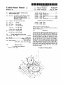
ABSTRACT
A toilet accessory (10) having readily detachable toilet seat
(14) and toilet lid (16). A hinge shaft (74) is supported by a
pair of posts (72) to protrude away from the housing (12).
Foreign Application Priority Data
Japan .................................. .. 6-036380
The hinge portions of the toilet seat and the toilet lid are
provided with elastic collars (84) of C-shaped cross-section
Int. (:1.6
............. .. A47K 13/12
US. Cl. .................................. .. 4/236; 4/447; 4/4204;
and are snap-?tted on the hinge shaft (74). When the toilet
4/420.2; 4/DIG. 6
cleaning, they can be readily dismounted only by pulling
with hands. To re-install, the hinge portions readily snap-?t
Field of Search .............................. .. 4/447, 240, 236,
4/237, DIG. 6, 420.2, 420.4, 486, 469,
473
[56]
8/1994
.. 4/447
Garrett & Dunner, L.L.P.
PCI‘ Pub. Date: Aug. 17, 1995
[JP]
5,341,517
Kurosawa et a1. .
Kobayashi et a1. .
Takedaet a1.
Vento
Attorney, Agent, or Firm-Finnegan, Henderson, Farabow,
[87] PCI‘ Pub. No.: WO94/21970
Feb. 10, 1994
11/1979 Wikstrom .................................. .. 4/236
12/1986
4/1991
6/1991
1/1994
Primary Examiner—David J. Walczak
Feb. 28, 1996
§ 102(e) Date: Feb. 28, 1996
[30]
4,173,8(72
4,628,548
5,010,601
5,025,511
5,279,001
61-49041
62441399
3-17754
Feb. 8, 1995 .
[86] PCT No:
Sep. 16, 1997
FOREIGN PATENT DOCUMENTS
[73] Assignee: Toto Ltd., Fukuoka, Japan
[21] Appl. No;
530,359
[22]
Date of Patent:
5,666,672
References Cited
U.S. PATENT DOCUMENTS
3,471,874 10/1969 Dixon.
seat and the toilet lid are to be removed for washing or
onv the hinge shaft by bringing the elastic collars (84) in
contact with the hinge shaft (74) and by pressing down the
hinge portions. Since the hinge shaft (74) and the posts (72)
are exposed out of the housing (12), they can be easily
accessed for cleaning.
22 Claims, 14 Drawing Sheets
US. Patent
Sep. 16, 1997
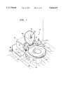
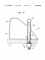
FIG. 1
Sheet 1 of 14
5,666,672
US. Patent
Sep. 16, 1997
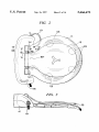
FIG. 2
Sheet 2 0f 14
5,666,672
US. Patent
Sep. 16, 1997
Sheet 3 0f 14
5,666,672
U.S. Patent
Sep. 16, 1997
FIG. 5
FIG. 6
Sheet 4 of 14
5,666,672
US. Patent
Sep. 16, 1997
Sheet 5 0f 14
FIG. 7
FIG. 9
ma
E
5,666,672
US. Patent
Sep. 16, 1997
‘FIG. 8B
Sheet 6 0f 14
FIG. 8C
5,666,672
US. Patent
Sep. 16, 1997
Sheet 7 0f 14
FIG. 10
5,666,672
US. Patent
Sep. 16,1997
Sheet 8 0f 14
5,666,672
FIG. 11A
7 FIG. 11B
FIG. 11C
US. Patent
Sep. 16,1997
Sheet 9 0114
'
FIG. 12A
FIG. 12B
FIG. 12C
5,666,672
US. Patent
Sep.16,1997
Sheet 10 0f 14
FIG. 13
FIG. 14
5,666,672
US. Patent
Sep. 16,1997
Sheet 11 0f 14
FIG. 15A
FIG. 15B
FIG. 15C
////////,
FIG. 151:
//
J
FIG. 15G
5,666,672
US. Patent
Sep. 16, 1997
F16IG.
12
Sheet 12 of 14
5,666,672
US. Patent
Sep. 16, 1997
6
17/?
Sheet 13 0f 14
FIG. 17
FIG. 1 7A
FIG. 17B
5,666,672
US. Patent
Sep.16, 1997
Sheet 14 0f 14
FIG. 18
‘
5,666,672
5 ,666,672
1
2
TOILET ATTACHMENT WITH EASILY
DETACHABLE SEAT
This hinge structure enjoys the advantage that the toilet
seat and the lid may readily be removed whenever desired
TECHNICAL FIELD
without using a tool such as a screw driver and a wrench.
The present invention relates to a combination of a toilet
accessory, such as a bidet system, bowl ventilation equip
ment and deodorizing device, and a toilet seat and a toilet lid
of the U-shaped jaws of the seat posts is not readily
However, one of the disadvantages is that the inner surface
accessible from the outside. In the event that the seat posts
are fouled by urine splashed too far during urination by a
male, it is difficult to wipe and clean the inner surface of the
jaws of the seat posts. Another shortcoming is that the toilet
seat and the toilet lid cannot be dismounted separately but,
hinged to the housing of the accessory. More speci?cally,
this invention relates to a toilet accessory having a toilet seat
and a toilet lid which may be readily detached from the
accessory for cleaning and easily re-installed.
BACKGROUND ART
Hitherto, various toilet accessories have widely been used
to add sanitary and/or electric functions to the conventional
toilets thereby to provide comfortable toilets. Such acces
sories include bidet systems, warmed water forming devices
instead, the seat and the lid as combined together can be
dismounted from the seat posts only jointly, the seat and the
lid being then separable from each other. Accordingly. it will
be discouraging for a user of weak muscle such as a
15 housewife or a handicapped to dismount the toilet seat and
the lid for routine cleaning of the toilet. Furthermore, two
steps of operations, i.e., rotation and pull, are required in
therefor, hot air blowers, bowl ventilation devices,
deodorizers, heated toilet seats, and toilet room heaters.
Typically, a housing for the accessory is mounted on the
order to dismount the toilet seat and the lid. If the toilet seat
is carelessly rotated when the two ?at sides of the hinge pin
20
upper surface of a toilet bowl ?xture between a bowl section
of the fixture and a ?ushing water supply section located
rearwardly of the bowl and one or more toilet accessories are
Accordingly, the primary object of the invention is to
arranged in the housing. For example, in a toilet described
in US. Pat. No. 4,628,548 to Kurosawa et a1, a bidet system
25
having a movable nozzle is arranged in the housing to eject
a spray of water toward the perineal part of the user seated
on the toilet seat so as to wash the anus and/or the vagina
after defecation or urination. The housing also receives a
warmed water reservoir for supplying warmed water to the
nozzle, a hot air blower for drying the perineal part after use
of the bidet system, a power source for the accessories and
30
an electric control device.
A toilet seat and a toilet lid are pivoted to the accessory
housing by associated hinge mechanisms. Generally, a hinge
of the seat are engaged within the slot formed between the
jaws of the seat posts or of the toilet lid, there is a risk that
the jaws are damaged or broken.
35
mechanism is designed in such a manner that the toilet seat
provide a combined toilet seat and accessory assembly
having a hinge mechanism which is simple in structure and
which is easy to clean.
Another object of the invention is to provide a hinge
structure for the assembly, which permits the toilet seat and
the toilet lid to be dismounted from the housing and
re-installed thereto separately from each other.
A still another object of the invention is to provide a hinge
structure for the assembly, by which the toilet seat and/or the
toilet lid may be readily detached from the housing and
readily re-installed thereto by a single operation.
A further object of the invention is to provide a hinge
and the lid may be removed from the housing for the purpose
structure which enables the toilet seat and/or the toilet lid to
of cleaning. To this end, the hinge pin is removably press
be readily removed ?'om and re-installed to the housing
?tted in a bore of the housing. However, removal of the
hinge pin in an attempt to detach the toilet seat and lid
regardless of the angular position thereof.
DISCLOSURE OF THE INVENTION
One of the features of the present invention is that a hinge
requires use of a tool such as a screw driver and pliers so that
it is difficult, if not possible at all, for an ordinary user, such
as a housewife, to remove the hinge pin in the course of
shaft of the hinge mechanism is supported on the housing by
routine household affairs. Furthermore, in many instances,
the hinge pin is coupled to the housing by means of a
pivoting movement control mechanism to prevent an abrupt
a pair of spaced posts so as to be spaced upwardly away from
the outer surface of the housing to a level higher than the
upper surface of the side portions of the toilet seat, the hinge
closure of the toilet seat and lid, as described in US. Pat. No.
5.0l0,601 to Kobayashi et al. In these instances, even a
portions of the toilet seat and the toilet lid being snap-?tted
fairly skilled user would be discouraged from attempting to
remove the hinge pin. In order to bravely dismount the toilet
seat and lid, the hinge pin must be carefully pulled out with
on the hinge shaft.
50
reference to a user’s manual. If it is not clear how to remove
the hinge pin, the toilet seat and lid may be detached only
with a potential risk of damaging the component parts.
US. Pat. No. 3,471,874 to Dixon discloses a hinge
the user may readily recognize that the toilet seat and the
toilet lid are designed detachable and may visually and
55
structure designed to enable even a housewife to easily
remove the toilet seat and lid. In this structure, a pair of seat
posts each having U-shaped jaws are mounted to the bowl
?xture. The toilet seat has a pair of hinge pins which has a
unique cross section de?ned by two ?at sides and two
circular sides to ensure that the hinge pins may be disen
gaged from the U-shaped jaws of the seat posts and
re-engaged when the toilet seat is rotated at a prescribed
angle coincident with the apertures of the U-shaped jaws.
The brackets of the toilet lid are also provided with the 65
U-shaped jaws which are removably engaged with the hinge
pins of the toilet seat.
Since in this way the hinge shaft is exposed upwardly of
the housing so that the presence of the hinge shaft is readily
perceived by the user, and because the hinge portions of the
toilet seat and the toilet lid are snap-?tted on the hinge shaft,
easily understand how they can be dismounted Accordingly,
the user is encouraged to remove the toilet seat and the toilet
lid for cleaning.
Furthermore, as the hinge portions of the toilet seat and
the toilet lid are snap-?tted on the hinge shaft, the toilet seat
and the toilet lid may readily be dismounted from the hinge
shaft by a single action of application of force regardless of
the angular position thereof and may be re-attached to the
shaft in an equally simple manner. The toilet seat and the
toilet lid may be detached separately where required
As the hinge shaft and the posts are simple in outer
con?guration, it is easy to clean the outer surface thereof
even though fouled by urine and the like. Since the hinge
5 ,666,672
4
3
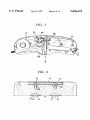
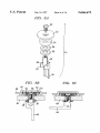
FIG. 5 is a plan view of a lower housing shown in FIG.
shaft is exposed upwardly of the housing, it can be readily
accessed for cleaning once the toilet seat and the toilet lid
4;
have been dismounted. The hinge shaft is less susceptible to
fouling by urine because it is located at a high level.
FIG. 6 is a front elevational view of the housing shown in
FIG. 1, with parts of the housing being cut away to show
slide rails;
Preferably, the posts supporting the hinge shaft are
arranged to extend only outwardly of the housing, without
projecting inwardly into the inner space of the housing. With
FIG. 7 is a perspective view of a conventional toilet bowl
this arrangement. the inner space of the housing may e?ec
?xture;
tively be used to accommodate various toilet accessories so
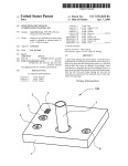
FIG. 8A is an exploded perspective view of a fastening
mechanism of the housing shown in FIG. 1;
that the housing may be made small and compact yet
1O
receiving more items of accessories.
In a preferred embodiment of the invention, the toilet seat
is provided with a backrest inclined rearwardly and
upwardly to support the pelvis of the user and the side
FIGS. 8B and 8C are enlarged cross-sectional views of the
slide rails shown in FIG. 6 and showing the manner in which
the housing is ?xed to the toilet bowl ?xture by the fastening
mechanism shown in FIG. 8A;
FIG. 9 is an enlarged cross-sectional view taken along the
portions of the toilet seat are provided with rearwardly and
downwardly inclined support surfaces. With this
arrangement, the perineal part of the user as seated on the
toilet seat is properly located with respect to a spray nozzle
of the bidet system so that the perineal part is effectively
washed.
Another feature of the invention is that the toilet seat is
ergonomically designed to ensure that the user may sit down
with ease. The toilet seat has a generally circular outer
periphery and an elongated seat opening. the side portions of
the toilet seat having wide support surfaces to better support
the thighs of the user. Preferably, the toilet seat is provided
with a forwardly and downwardly inclined frontal portion to
25
upper surface to ensure that the user in a bath room may
conveniently sit thereon for any purposes. The toilet lid rests
upon the toilet seat by way of a surface contact so that a
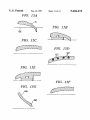
along the lines A—A, B-B, C—C. D-D, E—E, F—-F, and
G--G of FIG. 13, respectively, with the electric heater wire
35
portions of the toilet seat and the toilet lid comprises an
elastic member of a C-shaped cross-section. The elastic
member has a pair of opposite free ends adapted to resil
being omitted in ?gures other than FIG. 15D;
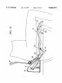
FIG. 16 is a cross-sectional view, taken along the central
plane, of the assembly shown in FIG. 1, with the bidet
system being shown as being in the operative position;
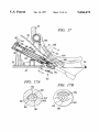
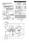
FIG. 17 is a cross-sectional view of the bidet system
shown in FIG. 16, with a plunger being shown as being in
iently grip the hinge shaft. Preferably, the elastic member is
supported by a bearing surface of a semicircular cross
section formed in the hinge portion in such a manner that a
its inoperative position;
FIGS. 17A and 17B are cross-sectional views taken along
spring action is developed by the opposite free ends of the
elastic member. The elastic member is preferably provided
with a pair of skirts ?aring out from the associated opposite
free ends to ensure that the elastic member is guided with
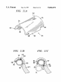
FIGS. 12A. 12B and 12C are views similar to FIGS. 11A.
11B and 11C, respectively, but showing a modi?ed version
of the elastic collar;
FIGS. 13 and 14 are top plan and side elevational views,
respectively, of the toilet seat shown in FIG. 1;
FIGS. 15A through 15G are cross-sectional views taken
facilitate the user seated on said seat to open the legs.
In a preferred embodiment, the toilet lid has a concave
su?icient mechanical strength necessary to support the
weight of the user is provided.
In another preferred embodiment, each of the hinge
line 1X—]X of FIG. 4;
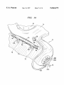
FIG. 10 is a perspective view of a part of the assembly
shown in FIG. 1, with the toilet seat and the toilet lid being
shown as being in their swung-up positions;
FIG. 11A is a perspective view of the elastic collar of the
hinge mechanism of the toilet seat and the toilet lid shown
in FIG. 1;
FIGS. 11B and 11C are cross-sectional views taken along
the lines X[B—X[B and XIC—XIC Of FIG. 2, respectively;
the lines A--A and B—B of FIG. 17, respectively; and,
FIG. 18 is a view similar to FIG. 9 but showing the
45
respect to the hinge shaft when the hinge portion is snap
?tted on the hinge shaft to re-install the toilet seat or the
toilet lid.
modi?ed forms of the hinge shaft, the posts thereof and the
housing.
BEST MODE FOR CARRYING OUT THE
INVENTION
Preferably, the housing is designed such that it is manu
ally and simply secured to the toilet bowl ?xture without
Referring to the drawings, the toilet accessory assembly
10 according to the invention includes a housing 12 as well
using a tool such as a wrench or spanner.
as {a toilet seat 14 and a toilet lid 16 hinged to the housing.
These features and advantages of the invention as well as
In the illustrated embodiment, the housing 12 receives a
other features and advantages thereof will become apparent
bidet system 18, a warmed water reservoir 20 therefor, and
from the following description.
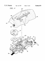
55 a deodorizer and ventilation fan unit 22, as best shown in
BRIEF DESCRIPTION OF THE DRAWINGS
FIG. 4.
As will be understood from FIG. 4, the housing may
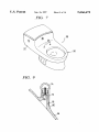
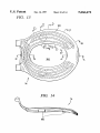
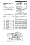
FIG. 1 is a perspective view of the combined toilet seat
conveniently be comprised of a lower housing 24 and an
and accessory assembly according to the invention as
mounted to a toilet bowl ?xture, with the toilet seat being
upper housing 26, which are made by molding of an impact
shown as being in its operative position and the toilet lid in
resistive plastic such as an acrylonitrile-butadiene-styrene
its inoperative position;
FIGS. 2 and 3 are top plan and side elevational views,
respectively, of the assembly shown in FIG. 1, with the toilet
lid being shown as being in the closed position;
FIG. 4 is an exploded perspective view of the housing of
the assembly shown in FIG. 1, with a water reservoir being
partly cut away to show an electric heater;
(ABS) resin. The lower housing 24 and the upper housing 26
are joined together by screws and the like, not shown, to
form an integral rigid housing 12.
65
The housing 12 is designed to be adaptive to the com
mercially available. conventional toilet bowl ?xtures. As
shown in FIG. 7, a conventional toilet bowl ?xture 28
includes a bowl section 30 and a ?ushing water supply
5 ,666,672
5
6
section such as a cistern 32. A pair of seat mounting holes
has a rearwardly and upwardly inclined ?'ont surface 76
from which the posts 72 extend upright. As shown in FIG.
9, the hinge shaft 74 and the posts 72 are integrally formed
34 spaced apart by a standardized predetermined distance
are formed between these sections. The housing 12 is
mounted on the upper surface of the toilet bowl ?xture 28 by
making use of these holes 34 as described later. Typically,
the popular toilet bowl ?xture is made in the form of a single
piece earthenware provided with a bowl section 30 and a
cistern 32 integral therewith and the front surface 36 of the
cistern is curved along the rear contour of the bowl 30, as
by molding of an ABS resin. Alternatively, they may be
made separately and ?rmly joined together by bolt and nut
or adhesives. Similarly, the hinge shaft 74, the posts 72 and
the upper housing 26 may all be molded to form a single
piece.
As shown in FIG. 9. the upper housing 26 is provided with
a pair of tubular supports 78 reinforced by respective bosses
80. The posts 72 are ?rmly joined with the supports 78 by
press-?tting the posts 72 over the supports 78 and by
screwing associated screws 82. The mating faces of the posts
shown. In the illustrated embodiment, therefore, the housing
12 is provided with an overall con?guration which is curved
along the curved front surface 36 of the cistern and. hence,
along the rear contour of the bowl 30, so as to be adapted to
the toilet bowl ?xture 28 of the popular design. However, the
housing 12 may be made in a more straight form. Also, the 15 72 and the supports 78 may be tapered upwardly so as to
establish a close ?t.
The hinge shaft 74 has a cylindrical outer periphery. The
the conventional toilet bowl ?xture having a separate cistern
toilet seat 14 and the toilet lid 16 are pivotally and detach
or a ?ushing valve.
housing 12 may equally be mounted to almost any type of
The housing 12 is designed to be readily secured to the
toilet bowl ?xture by a pair of levered fastening mechanisms
in a manner adjustable in the fore-and-aft direction. To this
end, as shown in FIGS. 6. 8B and 8C. the bottom plate 38
of the lower housing 24 is provided with two pairs of slide
rails 40 extending for a predetermined length in the longi
tudinal direction of the bowl ?xture, each pair of the slide
rails 40 forming a slot 42 of a T-shaped cross-section. The
distance between the two slots 42 is equal to the standard
ized distance between the seat mounting holes 34. As best
shown in FIG. 8A, each of the fastening mechanisms 44 may
be comprised of a pull rod 48 having a lock lever 46 pivoted
20
25
ably hinged to the hinge shaft by means of a plurality of
elastic collars 84. The toilet seat 14 has a pair of spaced
hinge portions 14H, as best shown in FIGS. 1 and 2, which
are snap-?tted respectively over the ends 74H (FIG. 4) of the
hinge shaft by the associated elastic collars 84 at locations
outwardly of the posts 72, as shown in FIG. 10. The toilet lid
16 has a single central hinge portion 16H which is snap
?tted over the central portion 74C of the hinge shaft by a pair
of elastic collars 84 at a location inwardly of the two posts
72.
As the snap-?t arrangements of the hinge portions 14H of
30
thereto and provided with a threaded bore, a screw 50
engageable with the pull rod 48, a dish-shaped retainer 52 of
sheet metal having an enlarged diameter and engageable
with the slide rails 40. an elastomeric ring 54, a pacldng 56
and a washer 58. The lock lever 46 has a curved cam surface 35
60 and a ?at locking surface 62.
To install the housing 12 onto the bowl ?xture 28, each of
the pull rods 48 loaded with the packing 56 and washer 58
is ?rst inserted from the underside of a ?ange 64 of the bowl
the toilet seat and the hinge portion 16H of the toilet lid are
basically the same, only the arrangement related to one of
the hinge portions 14H of the toilet seat will be described.
Referring to FIGS. 11A, 11B and 11C, the elastic collar 84
is made of a plastic material such as polypropylene and has
a generally C-shaped cross-section. The elastic collar 84 has
an inner diameter equal to the outer diameter of the hinge
shaft 74 and has a pair of opposite jaws 86. ‘The ends of the
jaws 86 are connected respectively to a pair of skirts 88
which are provided with tapered guide surfaces 90.
?xture upwardly into the associated seat mounting hole 34
and. after placing the elastomeric ring 54 and the retainer 52
The hinge portion 14H of the toilet seat is formed with a
bearing surface 92 of a semicircular cross-section having an
inner diameter equal to the outer diameter of the collar 84 to
on the upper surface of the ?ange 64, the screw 50 is then
screwed into the pull rod 48 to the degree that the elasto
meric ring 54 is not compressed, as shown in FIG. 8B. In this
support the collar 84 by the bearing surface 92. The collar 84
may be ?xed to the bearing surface 92 by means such as
state. the retainer 52 is spaced by the elastomer ring 54
upwardly away from the ?ange 64. Then the housing 12 is
adhesives. Preferably, however, the collar 84 is replaceably
and detachably mounted to the hinge portion 14H. For this
held and moved to bring the retainers 52 into engagement
with the slots 42 as shown in FIG. 8B. As the housing 12 is
slid rearwards until it is brought in an appropriate position
purpose, the collar 84 is provided at its ends with extensions
94 having a semicircular cross-section, the opposite ends of
each extension 94 being formed with beads 96, respectively.
on the bowl ?xture 28, the levers 46 are then rotated as 50 Each bead 96 is adapted to engage a corresponding notch 98
shown in FIG. 8C, whereupon the retainers 52 are pulled
downwards by the pull rods 48 to compress the elastomeric
ring 54 until the slide rails 40 are brought into tight contact
with the ?ange 64 thereby to ?x the ‘housing on the bowl
?xture.
As in this manner the housing 12 is secured to the bowl
?xture 28 by a single-touch manual operation of the levers
formed on the bearing surface 92 of the hinge portion 14H.
The elastic collar 84 is also provided with an outwardly
biased stopper 100 which is adapted to engage a notch 102
on the bearing surface 92 to prevent the axial displacement
55
of the collar 84. As will be understood from FIG. 11C, when
the elastic collar 84 is mounted to the hinge portion 14H, the
jaws 86 and the skirts 88 of the collar are protruded
46 without using a tool such as a wrench and spanner. it is
downwards beyond the bearing surface 92 so as not to
easy for an ordinary user to install the housing. To bring the
bidet system 18 in an operable condition, it will then suf?ce
to connect a water supply hose 66 to a branch adapter 68 in
interfere with the hinge portion 14H.
With this arrangement, whenever it is desired to dismount
the toilet seat 14 and/or the toilet lid 16 for cleaning, it will
be su?icient for the user to engage the hands under the hinge
a water line and to connect a plug of an electric cord 70 to
a plug socket, as shown in FIG. 1.
As best shown in FIGS. 4 and 10, at a level roughly equal
to the level of the top of the housing, a horizontal hinge shaft
74 is supported on the housing 12 by a pair of rigid posts or
supports 72. In the illustrated embodiment, the housing 12
65
portion 14H or 16H and to simply pull them upwards
whereupon the hinge shaft 74 will spread the jaws 86 apart
against the spring action so that the hinge portion is readily
disengaged from the hinge shaft as shown by the ghost line
in FIG. 11C. As the hinge shaft 74 as well as the posts 72
5,666,672
7
8
have simply cylindrical outer surfaces. they can be easily
of water ejected from the nozzle to hit on the target point 114
cleaned such as by wiping once the toilet seat 14 and the
toilet lid 16 have been removed. To re-install the toilet seat
14 and/or the toilet lid 16, the skirts 88 of the elastic collar
at the perineal part to effectively wash that part.
As best shown in FIG. 13, the side portions 145 of the
toilet seat are designed to provide wider support surfaces for
supporting the thighs of the user. To this end, the toilet seat
84 are brought into engagement with the hinge shaft 74 and
the hinge portion 14H or 16H is then pressed down by hands.
The hinge shaft 74 will urge the skirts 88 and the jaws 86 to
be spaced apart on entering into the inside of the elastic
collar 84. Finally, the jaws 86 will resiliently grip the hinge
shaft 74 under the spring-back action so that the elastic
collar 84 is snap-?tted on the hinge shaft 74 as shown by the
solid line.
In this manner. the toilet seat 14 and the toilet lid 16 may
be easily dismounted by anyone only by a single manual
operation and may be equally easily re-installed. As the snap
action of the C-shaped elastic collars is readily understood
by anyone at a glance, the user will quickly recognize that
10
14 has a generally circular outer periphery and the inner
periphery de?ning a seat opening 116 has an elongated
contour. As after excretion the perineal part is washed by the
bidet system 18, normally it would not be necessary to wipe
the perineal part. Accordingly, it is preferable to design the
seat opening 116 as narrow as possible in order to widen the
support surface at the side portions 145 thereby to improve
the support for the thighs. The side portions 148 of the toilet
seat has a transverse width of about 9 cm and the seat
15 opening 116 has a transverse width of about 15 cm.
The front portion 14F of the toilet seat is inclined for
wardly and downwardly as best shown in FIGS. 15B, 15A
the toilet seat and the toilet lid are detachable and how they
and 16. Consequently, the user is assisted in opening the legs
can be detached. The removal and re-installation of the toilet
seat 14 and the toilet lid 16 may be carried out mostly 20 to assume an easy posture. The downward inclination of the
front portion 14F also serves to form a gap or clearance 118
without regard to the angular position thereof. In general,
between the front portion of the toilet seat and the front
however, it will be convenient to dismount and re-attach
portion of the toilet lid as shown in FIG. 3. The user may
them when they are in the horizontal position. As will be
apparent from FIG. 10, the posts 72 and the hinge shaft 74
may be provided with stoppers 103 against which the end
faces of the hinge portions of the toilet seat 14 and the toilet
easily lift the toilet lid 16 by inserting the ?ngers into the gap
to grip the toilet lid.
25
lid 16 are brought into abutment to limit the angle of
rotational movement of the toilet seat 14 and the toilet lid 16.
In FIGS. 12A, 12B and 12C, there is shown a modi?ed
embodiment of the elastic collars and the associated hinge
portions. Parts and members similar to those of the forego
ing embodiment are indicated by like reference numerals
with a su?ix A and will not be described again. In the
modi?ed embodiment. the elastic collar 84A has a slightly
elongated cross-section and the bearing surface 92A of the
hinge portion has a correspondingly elongated cross-section.
The central portion of the elastic collar 84A is provided with
a C-shaped cut out to form a cushioning portion 104 which
is bulged radially inwardly. When the toilet seat 14 and the
toilet lid 16 are unloaded, the elastic collar 84A will engage
the hinge shaft 74 by a three point contact as shown in FIG.
‘
The toilet seat 14 and the toilet lid 16 may be manufac
tured by molding of an impact resistive plastic such as an
ABS resin. As will be understood from FIGS. 1 and 3, the
toilet lid 16 has a concave upper surface to ensure that the
user may sit down for any purposes like a chair. The toilet
lid 16 has a thickness and a mechanical strength sufficient to
35
withstand the weight of the user and is adapted to rest, by a
surface contact, upon the side portions 148 and the front part
14F of the toilet seat when in use. As shown in FIG. 1. the
toilet lid 16 is provided with through-openings 120 which
represent the symbol of a fountain. The symbol of fountain
appeals the presence of the bidet system 18 to the user who
uses the assembly 10 for the ?rst time so that the user is
reminded of the use of the bidet system. Furthermore, when
water is accumulated on the toilet for any reasons such as the
use of a shower, the through-openings 120 permit water to
be drained into the bowl.
In the illustrated embodiment, the toilet seat 14 is adapted
top of the bearing sln'face 92A of the hinge portion and the
to be heated by an electric heater to heat the user seated
hinge shaft. As the user sits down so that the toilet seat 14
or the toilet lid 16 is loaded, the cushioning portion 104 45 thereon in the cold season. As shown in FIGS. 13 and 15D,
a sinusoidal heater wire 122 is embedded in the toilet seat
undergoes elastic deformation as shown in FIG. 12C thereby
14. The heater wire 122 is omitted in the other drawings for
to subdue or cushion the impact of loading.
simplicity. The electric power to the heater wire 12 is
Referring to FIGS. 1, 13 and 14. the toilet seat 14 may
supplied from an electric cord 124. As shown in FIG. 10, an
include a pair of side portions 145, a rear portion 14R, a
front portion 14F and a backrest 14B. A plurality of rubber 50 electric receptacle 126 connected to the heater wire 122 is
arranged on the lower side of the toilet seat 14 and a
bumpers 106. numbering four for example, are a?ixed to the
connector plug 128 disposed at an end of the cord 124 is
underside of the toilet seat to support the toilet seat on the
connected to the receptacle 126. The electric cord 124
upper surface of the rim 108 of the toilet bowl ?xture 28 as
preferably has such a length that, when the toilet seat is
shown in FIG. 16.
swung up, an adequate slack remains in the cord to permit
As will be apparent from FIGS. 1, 14, 15G and 16, the
a smooth rotation of the toilet seat. A temperature sensor
backrest 14B of the toilet seat extends rearwardly and
such as a thermistor, not shown. is embedded in the toilet
upwardly at a steep angle from the rear portion 14R so as to
seat 14 in the conventional manner. The power supply to the
support and locate the pelvis of the user. In addition, as
12B so that a small clearance will be secured between the
shown in FIGS. 14. 15C-15F and 16, the side portions 143
heater is controlled by a control unit, described later, in
of the toilet seat are inclined rearwardly and downwardly
response to the signal from the sensor in such a manner that
toward the rear portion 14R so as to bias and locate the
the toilet seat is heated at a desired ‘appropriate temperature.
As shown in FIGS. 4 and 5, the bidet system 18 is
buttocks of the user rearwardly toward the backrest 14B.
With this arrangement, whenever the user is to be seated on
the toilet seat, the user is assisted to easily occupy such a
arranged at the center of the housing 12. The bidet system
may be the conventional one. However, a simple form of the
position that the perineal part of the user is properly posi 65 bidet system which can be manufactured at low costs and
which is suitable to be incorporated into the assembly 10
tioned with respect to a protracted nozzle 110 of the bidet
according to the invention will be described below by way
system 18, as shown in FIG. 16. thereby assuring a spray 112
5,666,672
9
10
of an example with reference to FIG. 17. The bidet system
18 includes a cylinder 130 which is secured to supports 132
130 in a slidable manner. Formed between the cylinder 130
and the plunger 136 is a spring chamber 138 in which a
inlet 144 of the bidet system through a hose 182. To facilitate
connection to the branch adapter '68, the water hose 66 is
preferably made of a ?exible hose sheathed with a metal
mesh. The valve unit 176 may comprise apressure reduction
valve, a solenoid operated shutoff valve and a ?ow rate
control valve in the conventional manner, with the shut-01f
compression spring 140 is arranged to bias the plunger 136
valve being controlled by a control unit 184 having a power
extending from the lower housing 24. Aplunger 136 having
an integral piston 134 is clearance ?tted within the cylinder
to a retracted position shown by the solid line.
An axial passage 142 is formed to extend through the
piston 134 and the plunger 136 and is in constant commu
nication with a water inlet 144 of the cylinder 130. The inlet
144, in turn, is in communication with the spring chamber
138 via a small radial clearance between the cylinder 130
and the piston 134. Accordingly, when water under pressure
is supplied to the inlet 144, water will flow into both the
source circuit and a microcomputer. As shown in FIG. 4, a
heat exchanger 186 incorporating an electric heater con
trolled by the control unit 184 is arranged in the warmed
water reservoir 20 to heat water in the reservoir.
In the illustrated embodiment, the housing 12 further
15
receives the conventional deodorizer and ventilation fan unit
22 to ventilate the bowl 30 and to deodorize the ventilated
air during use of the toilet. As shown in FIGS. 4 and 5, the
passage 142 and the spring chamber 138.
As shown in FIG. 17A, the end wall 146 of the cylinder
bottom plate 38 of the lower housing 24 is provided with an
opening 188 facing the bowl 30, the opening being com
130 is formed with a circular opening 148 in which the
head 110 is mounted to the forward end of the plunger 136.
As will be apparent from FIG. 17A, the upper part of the
municated with the ventilation unit 22 through a duct formed
by a vertical enclosing wall 190 and a cover 192 therefor.
The deodorizer and ventilation fan unit 22 may be of the
conventional one having an air passage charged with acti
plunger 136 is chamfered substantially throughout the entire
vated carbon and deodorizing catalyst and is adapted to draw
length thereof so that a water outlet 152 is formed between
the circular opening 148 of the end wall 146 and the outer
and deodorize air Within the bowl and to circulate processed
air into the ambient atmosphere. The deodorizer and venti
lation fan unit 22 is automatically controlled by the control
unit 184. To this end, the upper housing 26 is provided with
forward part of the plunger 136 is slidably guided. A nozzle
periphery of the plunger 136 throughout the stroke of the
25
plunger 136. As a result, when water under pressure is
supplied to the water inlet 144, water entering the spring
chamber 138 will be ejected from the outlet 152 to wash the
nozzle head 110. As shown in FIG. 17B, a cover 154 of a
semicircular cross-section is arranged to project from the
30
the user. The control unit automatically operates the deodor
izer and ventilation fan unit 22 as long as the user as seated
on the toilet seat 14 is detected by the signal from the
end wall 146 of the cylinder 130 so as to direct water ejected
from the outlet 152 to ?ow along the nozzle head 110
thereby to effectively wash the nozzle head 110.
A packing 156 is arranged inwardly of the end wall 146
of the cylinder 130. When the plunger 136 is fully stroked
as shown by the imaginary line in FIG. 17, the shoulder 158
of the plunger 136 abuts against the packing 156 to shut off
the ?ow of water through the outlet 152. As shown in FIG.
17A, the side of the plunger 136 is provided with a spline
160 which is slidably engaged with a notch 162 formed in
infrared sensor.
35
Once the housing 12 is mounted to the toilet bowl ?xture
28 in a manner described before, and upon connecting the
45
hose 66 to the branch adapter 68 with the plug of the cord
70 connected to the plug socket, the bidet system 18 will be
ready for use. As the user is seated on the toilet seat 14 and
restriction 164 of a reduced diameter. Due to the presence of
presses on the switch 198, the solenoid valve of the valve
unit 176 of the bidet system 18 is opened to allow tap water
under pressure to ?ow into the warmed water reservoir 20 so
that warmed water in the reservoir is displaced toward the
inlet 144 of the bidet system 18. This causes warmed water
under pressure to ?ow into the spring chamber 138 and the
passage 142 whereby the plunger 136 commences its for
ward stroke and. at the same time, water in the spring
the restriction 164, the water pressure acting on the piston
134 becomes higher than the atmospheric pressure prevail
ing in the spring chamber 138 when water under pres sure is
supplied to the water inlet 144, thereby causing the plunger
132 to stroke against the action of the return spring 140.
In the illustrated embodiment, the nozzle head 110 is
designed to form and eject a frothed spray. The nozzle head
110 may be made for example in a cylindrical form and
As shown in FIG. 10, the housing 12 is provided at the
side thereof with a control switch 198 for the bidet system
18, a switch 200 for operating the electric heater of the
reservoir 20, and a switch 202 for operating the heater 122
of the heated seat 14, these switches being connected to the
control unit 184.
the end wall 146. By the splined engagement, the plunger
136 is held in a predetermined angular position during the
telescoping movement.
The passage 142 of the plunger 132 is in communication
with the inner passage of the nozzle head 110 through a
an opaque sensor window 196 permeable to an infrared ray
to ensure that an infrared ray is transmitted upwardly from
a conventional infrared sensor, not shown, to detect the
presence of the user in accordance with the ray re?ected by
55
chamber 138 is delivered from the outlet 152 to wash the
nozzle head 110.
includes a radial passage 166 cormnunicated with the ori?ce
164, an axial passage 168 having a reduced diameter to
When the plunger 136 has fully stroked, the outlet 152 is
provide a venturi elfect, and an outlet port 170. An air intake
closed by the plunger shoulder 158 abutting against the
port 172 opens into the venturi passage 168 to introduce by
pacldng 156 whereupon warmed water is permitted to ?ow
the venturi effect air bubbles into the water ?ow ?owing
out only through the nozzle head 110 thereby fonning a
through the passage 168.
frothed spray 112 as shown in FIG. 16. Since the user is
located by the toilet seat 14 such that the perineal part of the
Warmed water is supplied from the warmed water reser
user is brought at the target point 114 as described before,
voir 20 to the bidet system 18. Referring to FIGS. 1, 4 and
the frothed spray hits on the perineal part to e?’ectively wash
5, tap Water may be fed to the reservoir 20 via the water hose
66, a hose 174 extending within the housing. a conventional 65 that part.
valve unit 176, a conventional vacuum breaker 178, and a
To terminate use of the bidet system 18, it is su?icient to
hose 180. The warmed water reservoir 20 is connected to the
press on the switch 198 again. The solenoid valve is then