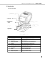
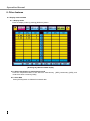
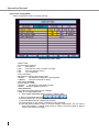
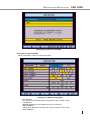
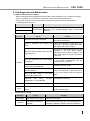
1
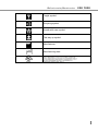
Refractometer/Keratometer ERK 7800 1 Operation Manual IMPORTANT NOTICE This product is always protected whbaen you connect the power supply must be connected to ground included. The ERK 7800 is classified as Class I. - Degree of protection against electric shock ; Type B Applied part Degree of protection against ingress of water level : None Mode of operation : Continuous operation A Class I is a product in which the protection against electric shock does not rely on basic insulation only, but which includes an additional safety precaution in such a way that means are provided for the connection of the product to the protective (ground) conductor in the fixed wiring of the installation in such a way that accessible metal parts cannot become live in the event of a failure in the basic insulation. Use a power outlet which is equipped with a grounding terminal. This product may malfunction due to electromagnetic waves caused by portable personal telephones, transceivers, radio-controlled toys, etc. Be sure to avoid having objects such as, which affect this product, brought near the product. It should be used under the supervision of medical staff of hospital The information in this publication has been carefully checked and is believed to be entirely accurate at the time of publication. ERK 7800 assumes no responsibility, however, for possible errors or omissions, or for any consequences resulting from the No use of the information contained herein. ERK 7800 reserves the right to make changes in its products or product specifications at any time and without prior notice, and is not required to update this documentation to reflect such changes. Under copyright laws, this manual may not be copied, in whole or in part, without the prior written consent of ERK 7800 2 Refractometer/Keratometer ERK 7800 SAFETY INFORMATION Accessory equipment connected to the analog and digital interfaces must be certificated according to the respective IEC/EN standards (e.g. IEC/EN 60950 for data processing equipment and IEC/EN 60601-1 for medical equipment). Furthermore all configurations shall comply with the system standard EN 60601-1-2:2007. If you connect additional equipment to the signal input or signal output of this device, then you are configuring a medical system, and are therefore responsible that the system complies with the requirements of the system standard EN 60601-1-1:2001. If in doubt, consult the technical service department or your local representative. For EU Countries The following mark, the name & address of the EU Representative shows compliance of the instrument with Directive 93/42/EEC. ISO 15004 This report provides information about the hazard to the examinee’s eyed in compliance with ISO 15004-1:2006, ISO 15004-2:2007 Ophthalmic instruments – Fundamental requirements and test methods Part2– Light hazard protection. This condition is satisfied even when the instrument is operating at maximum light intensity and maximum aperture! (Maximum intensity is the highest brightness the instrument is capable of delivering, including the highest brightness achievable if overvoltage is provided) detailed radiation information at normal usage of this instrument is like bellows. Radiation output: below 117.1 μW/cm2 Limit by ISO15004: 100 mW/cm2 Number 1 2 3 4 5 6 7 8 9 10 Radiation output [μW/cm2] 107.0 117.1 115.5 115.7 103.6 103.7 108.8 109.0 105.6 105.8 average 109.1 0120 3 Operation Manual SYMBOLS Symbol Descriptions TYPE B EQUIPMENT Protective earth (ground) Alternating current Off (power: disconnected from mains) On (power: connection to mains) Do not dispose of inappropriately Risk of electric shock Crushing hazard sign Hand hazard sign Instruction for user manual General mandatory action sign General prohibition sign General warning, caution sign Keep dry symbol DO NOT use hooks symbol 4 Refractometer/Keratometer ERK 7800 Fragile symbol Recycling symbol Handle with care symbol This way up symbol Manufacturer Manufacturing date 5 Operation Manual GENERAL SAFETY INFORMATION If you see any warnings or cautions printed on the warning labels, follow the safety instructions in this manual. Ignoring such cautions or warnings while handling the product may result in injury or accident. Be sure to read and fully understand the manual before using this product. Keep this manual in an easy-to-access place. Safety Symbols and sign This indicates hazardous situations which may result in electrical shock to you. This indicates hazardous situations which may result in crush your hand. This indicates hazardous situations which may result insert your hand. This indicates hazardous situations which may result in minor injury to you or others, or may result in machine damage. This indicates a mandatory action. If you do not act accordingly, this may result in death or serious injury to you or others. This indicates a hazardous situation which could result in death or serious injury to you or others. NOTE This is used to emphasize essential information. Be sure to read this information to avoid incorrect operation. 6 Refractometer/Keratometer ERK 7800 INDEX IMPORTANT NOTICE ∙ ∙ ∙ ∙ ∙ ∙ ∙ ∙ ∙ ∙ ∙ ∙ ∙ ∙ ∙ ∙ ∙ ∙ ∙ ∙ ∙ ∙ ∙ ∙ ∙ ∙ ∙ ∙ ∙ ∙ ∙ ∙ ∙ ∙ ∙ ∙ ∙ ∙ ∙ ∙ ∙ ∙ ∙ ∙ ∙ ∙ ∙ ∙ ∙ ∙ ∙ ∙ ∙ ∙ ∙ ∙ ∙ ∙ 1 SAFETY INFORMATION ∙∙ ∙ ∙ ∙ ∙ ∙ ∙ ∙ ∙ ∙ ∙ ∙ ∙ ∙ ∙ ∙ ∙ ∙ ∙ ∙ ∙ ∙ ∙ ∙ ∙ ∙ ∙ ∙ ∙ ∙ ∙ ∙ ∙ ∙ ∙ ∙ ∙ ∙ ∙ ∙ ∙ ∙ ∙ ∙ ∙ ∙ ∙ ∙ ∙ ∙ ∙ ∙ ∙ ∙ ∙ ∙ ∙2 SYMBOLS ∙ ∙ ∙ ∙ ∙ ∙ ∙ ∙ ∙ ∙ ∙ ∙ ∙ ∙ ∙ ∙ ∙ ∙ ∙ ∙ ∙ ∙ ∙ ∙ ∙ ∙ ∙ ∙ ∙ ∙ ∙ ∙ ∙ ∙ ∙ ∙ ∙ ∙ ∙∙ ∙ ∙ ∙ ∙∙ ∙ ∙ ∙ ∙∙ ∙ ∙ ∙ ∙∙ ∙ ∙ ∙ ∙∙ ∙ ∙ ∙ ∙ ∙ ∙ ∙ ∙ ∙ ∙ ∙ ∙ ∙3 GENERAL SAFETY INFORMATION ∙ ∙ ∙ ∙ ∙ ∙ ∙ ∙ ∙ ∙ ∙ ∙ ∙ ∙ ∙ ∙ ∙ ∙ ∙ ∙ ∙ ∙ ∙ ∙ ∙ ∙ ∙ ∙ ∙ ∙ ∙ ∙ ∙ ∙ ∙ ∙ ∙ ∙ ∙ ∙ ∙ ∙ ∙ ∙ ∙ ∙ ∙ ∙ ∙5 1. 2. 3. 4. Features and Intended Use ∙∙ ∙ ∙ ∙ ∙ ∙ ∙ ∙ ∙ ∙ ∙ ∙ ∙ ∙ ∙ ∙ ∙ ∙ ∙ ∙ ∙ ∙ ∙ ∙ ∙ ∙ ∙ ∙ ∙ ∙ ∙ ∙ ∙ ∙ ∙ ∙ ∙ ∙ ∙ ∙ ∙ ∙ ∙ ∙ ∙ ∙ ∙ 8 Notes for Using the Instrument ∙ ∙ ∙ ∙ ∙ ∙ ∙ ∙ ∙ ∙ ∙ ∙ ∙ ∙ ∙ ∙ ∙ ∙ ∙ ∙ ∙ ∙ ∙ ∙ ∙ ∙ ∙ ∙ ∙ ∙ ∙ ∙ ∙ ∙ ∙ ∙ ∙ ∙ ∙ ∙9 Prerequisites for safety∙ ∙ ∙ ∙ ∙ ∙ ∙ ∙ ∙ ∙ ∙ ∙ ∙ ∙ ∙ ∙ ∙ ∙ ∙ ∙ ∙ ∙ ∙ ∙ ∙ ∙ ∙ ∙ ∙ ∙ ∙ ∙ ∙ ∙ ∙ ∙ ∙ ∙ ∙ ∙11 Introduction ∙∙∙∙∙∙ ∙ ∙ ∙ ∙ ∙ ∙ ∙ ∙ ∙ ∙ ∙ ∙ ∙ ∙ ∙ ∙ ∙ ∙ ∙ ∙ ∙ ∙ ∙ ∙ ∙ ∙ ∙ ∙ ∙ ∙ ∙ ∙ ∙ ∙ ∙ ∙ ∙ ∙ ∙ ∙ ∙ ∙ ∙ ∙ ∙ ∙ ∙ ∙ ∙ ∙ ∙ ∙ ∙ ∙ ∙ ∙12 Front side of body ∙ ∙ ∙ ∙ ∙ ∙ ∙∙∙ ∙ ∙ ∙ ∙ ∙ ∙ ∙ ∙ ∙ ∙ ∙ ∙ ∙ ∙ ∙ ∙ ∙ ∙ ∙ ∙ ∙ ∙ ∙ ∙ ∙ ∙ ∙ ∙ ∙ ∙ ∙ ∙ ∙ ∙ ∙ ∙ ∙ ∙ ∙ ∙ ∙ 12 Back side of body ∙ ∙ ∙ ∙ ∙ ∙ ∙ ∙ ∙ ∙ ∙ ∙ ∙ ∙ ∙ ∙ ∙ ∙ ∙ ∙ ∙ ∙ ∙ ∙ ∙ ∙ ∙ ∙ ∙ ∙ ∙ ∙ ∙ ∙ ∙ ∙ ∙ ∙ ∙ ∙ ∙ ∙ ∙ ∙ ∙ ∙ ∙ ∙ 13 Bottom side of body ∙ ∙ ∙ ∙ ∙ ∙ ∙ ∙∙∙ ∙ ∙ ∙ ∙ ∙ ∙ ∙ ∙ ∙ ∙ ∙ ∙ ∙ ∙ ∙ ∙ ∙ ∙ ∙ ∙ ∙ ∙ ∙ ∙ ∙ ∙ ∙ ∙ ∙ ∙ ∙ ∙ ∙ ∙ ∙ ∙ ∙ ∙ ∙14 Operation Buttons ∙ ∙ ∙ ∙ ∙ ∙ ∙ ∙ ∙ ∙ ∙ ∙ ∙ ∙ ∙ ∙ ∙ ∙ ∙ ∙ ∙ ∙ ∙ ∙ ∙ ∙ ∙ ∙ ∙ ∙ ∙ ∙ ∙ ∙ ∙ ∙ ∙ ∙ ∙ ∙ ∙ ∙ ∙ ∙ ∙ ∙15 Equipment Installation and Measurement Preparation ∙ ∙ ∙∙ ∙ ∙ ∙ ∙ ∙ ∙ ∙ ∙ ∙ ∙ ∙ ∙ ∙ ∙ 16 Practicing with the Model Eye ∙ ∙ ∙ ∙ ∙ ∙ ∙ ∙ ∙ ∙ ∙ ∙ ∙ ∙ ∙ ∙ ∙ ∙ ∙ ∙ ∙ ∙ ∙ ∙ ∙ ∙ ∙ ∙ ∙ ∙ ∙ ∙ ∙ ∙ ∙ ∙ ∙ ∙ ∙ ∙ ∙ ∙ ∙ 17 Measurement Functions ∙ ∙ ∙ ∙ ∙ ∙ ∙ ∙ ∙ ∙ ∙ ∙ ∙ ∙ ∙ ∙ ∙ ∙ ∙ ∙ ∙ ∙ ∙ ∙ ∙ ∙ ∙ ∙ ∙ ∙ ∙ ∙ ∙ ∙ ∙ ∙ ∙ ∙ ∙ ∙ ∙ ∙ ∙ ∙ 19 7.1 Measurement process ∙ ∙ ∙ ∙ ∙ ∙∙ ∙ ∙ ∙ ∙ ∙∙ ∙ ∙ ∙ ∙ ∙ ∙ ∙ ∙ ∙ ∙ ∙ ∙ ∙ ∙ ∙ ∙ ∙ ∙ ∙ ∙ ∙ ∙ ∙ ∙ ∙ ∙ ∙ ∙ ∙ ∙ ∙ ∙ ∙ ∙ ∙ ∙ 19 7.1.1 Mode selection ∙ ∙ ∙ ∙ ∙ ∙ ∙ ∙ ∙ ∙ ∙ ∙ ∙ ∙ ∙ ∙ ∙ ∙ ∙ ∙ ∙ ∙ ∙ ∙ ∙ ∙ ∙ ∙ ∙ ∙ ∙ ∙ ∙ ∙ ∙ ∙ ∙ ∙ ∙ ∙ ∙ ∙ ∙ ∙ ∙ ∙ 19 7.1.2 Regulating eye level of patient ∙ ∙ ∙ ∙ ∙ ∙ ∙ ∙ ∙ ∙ ∙ ∙ ∙ ∙ ∙ ∙ ∙ ∙ ∙ ∙ ∙ ∙ ∙ ∙ ∙ ∙ ∙ ∙ ∙ ∙ ∙ ∙ ∙ ∙ ∙ 19 7.1.3 Focusing ∙ ∙ ∙ ∙ ∙ ∙ ∙ ∙ ∙ ∙ ∙ ∙ ∙ ∙ ∙ ∙ ∙ ∙ ∙ ∙ ∙ ∙ ∙ ∙ ∙ ∙ ∙ ∙ ∙ ∙ ∙ ∙ ∙ ∙ ∙ ∙ ∙∙ ∙ ∙ ∙ ∙ ∙ ∙∙ ∙ ∙ ∙ ∙ ∙ ∙ ∙ ∙ 19 7.1.4 Manual Measurement ∙ ∙ ∙ ∙ ∙ ∙ ∙ ∙ ∙ ∙ ∙ ∙ ∙ ∙ ∙ ∙ ∙ ∙ ∙ ∙ ∙ ∙ ∙ ∙ ∙ ∙ ∙ ∙ ∙ ∙ ∙ ∙ ∙ ∙ ∙ ∙ ∙ ∙ ∙ ∙ ∙ ∙ 19 7.1.5 Continuous Measurement ∙ ∙ ∙ ∙ ∙ ∙ ∙ ∙ ∙ ∙ ∙ ∙ ∙ ∙ ∙ ∙ ∙ ∙ ∙ ∙ ∙ ∙ ∙ ∙ ∙ ∙ ∙ ∙ ∙ ∙ ∙ ∙ ∙ ∙ ∙ ∙ ∙ 19 7.1.6 Measure other eye ∙ ∙ ∙ ∙ ∙ ∙ ∙ ∙ ∙ ∙ ∙ ∙ ∙ ∙ ∙ ∙ ∙ ∙ ∙ ∙ ∙ ∙ ∙ ∙ ∙ ∙ ∙ ∙ ∙ ∙ ∙ ∙ ∙ ∙ ∙ ∙ ∙ ∙ ∙ ∙ ∙ ∙ ∙ ∙ ∙19 7.1.7 Printing ∙ ∙ ∙ ∙ ∙ ∙ ∙ ∙ ∙ ∙ ∙ ∙ ∙ ∙ ∙ ∙ ∙ ∙ ∙ ∙ ∙ ∙ ∙ ∙ ∙ ∙ ∙ ∙ ∙ ∙ ∙ ∙ ∙ ∙ ∙ ∙ ∙ ∙ ∙ ∙ ∙ ∙ ∙ ∙ ∙ ∙ ∙ ∙ ∙ ∙ ∙ 19 7.1.8 Automatic measuring ∙ ∙ ∙ ∙ ∙∙ ∙ ∙ ∙ ∙ ∙ ∙ ∙ ∙ ∙ ∙∙ ∙ ∙ ∙ ∙ ∙ ∙ ∙ ∙ ∙ ∙ ∙ ∙ ∙ ∙ ∙ ∙ ∙ ∙ ∙ ∙ ∙ ∙ ∙ ∙ ∙ ∙ ∙ ∙ ∙ ∙19 7.2 REF MODE ∙ ∙ ∙ ∙ ∙ ∙ ∙ ∙ ∙ ∙ ∙ ∙ ∙ ∙ ∙ ∙ ∙ ∙ ∙ ∙ ∙ ∙ ∙ ∙ ∙ ∙ ∙ ∙ ∙ ∙ ∙ ∙ ∙ ∙ ∙ ∙ ∙ ∙ ∙ ∙ ∙ ∙ 20 7.3 KER MODE ∙ ∙ ∙ ∙ ∙ ∙ ∙ ∙ ∙ ∙ ∙ ∙ ∙ ∙ ∙ ∙ ∙ ∙ ∙ ∙ ∙ ∙ ∙ ∙ ∙ ∙ ∙ ∙ ∙ ∙ ∙ ∙ ∙ ∙ ∙ ∙ ∙ ∙ ∙ ∙ ∙ ∙ ∙ ∙21 7.4 Keratometry and refractometry (RK MODE) ∙ ∙ ∙ ∙ ∙∙ ∙ ∙ ∙ ∙∙ ∙ ∙ ∙ ∙ ∙∙ ∙ ∙ ∙ ∙ ∙∙ ∙∙ ∙ ∙ ∙ ∙ 22 7.5 Measuring contact lenses base curve (CLBC MODE) ∙ ∙ ∙ ∙ ∙ ∙ ∙ ∙ ∙ ∙ ∙ ∙ ∙ ∙ ∙ ∙ ∙ ∙ ∙ ∙ ∙ 23 7.5.1 Attach contact lens ∙ ∙ ∙ ∙ ∙ ∙ ∙ ∙ ∙ ∙ ∙ ∙ ∙ ∙ ∙ ∙ ∙ ∙ ∙ ∙ ∙ ∙ ∙ ∙ ∙ ∙ ∙ ∙ ∙ ∙ ∙ ∙ ∙ ∙ ∙ ∙ ∙ ∙ ∙ ∙ ∙ ∙ ∙ ∙ ∙23 7.5.2 Attach model eye with contact lens ∙ ∙ ∙ ∙ ∙ ∙ ∙ ∙ ∙ ∙ ∙ ∙ ∙ ∙ ∙ ∙ ∙ ∙ ∙ ∙ ∙ ∙ ∙ ∙ ∙ ∙ ∙ ∙ ∙ ∙ 23 7.6 Measuring cornea size (SIZE MODE)∙ ∙ ∙ ∙ ∙ ∙ ∙ ∙ ∙ ∙ ∙ ∙ ∙ ∙ ∙ ∙ ∙ ∙ ∙ ∙ ∙ ∙ ∙ ∙ ∙ ∙ ∙ ∙ 24 7.6.1 Operating buttons∙ ∙ ∙ ∙ ∙ ∙ ∙ ∙ ∙ ∙ ∙ ∙ ∙ ∙ ∙ ∙ ∙ ∙ ∙ ∙ ∙ ∙ ∙ ∙ ∙ ∙ ∙ ∙ ∙ ∙ ∙ ∙ ∙ ∙ ∙ ∙ ∙ ∙ ∙ ∙ ∙24 7.6.2 Measurement selection∙ ∙ ∙ ∙ ∙ ∙ ∙∙ ∙ ∙∙ ∙ ∙ ∙∙ ∙ ∙ ∙ ∙∙ ∙ ∙ ∙ ∙∙ ∙ ∙ ∙ ∙ ∙ ∙ ∙ ∙ ∙ ∙ ∙ ∙ ∙ ∙ ∙ ∙ ∙ ∙ ∙ ∙ ∙ ∙ 24 7.6.3 Determine size∙ ∙ ∙ ∙ ∙ ∙ ∙ ∙ ∙ ∙ ∙ ∙ ∙ ∙ ∙ ∙ ∙ ∙ ∙ ∙∙ ∙ ∙ ∙ ∙ ∙ ∙ ∙ ∙ ∙ ∙ ∙ ∙ ∙ ∙ ∙ ∙ ∙ ∙ ∙ ∙ ∙ ∙ ∙ ∙ ∙ 25 7.7 Pupil and cornea observing function (ILLUM MODE) ∙ ∙ ∙ ∙ ∙ ∙ ∙ ∙ ∙ ∙ ∙ ∙ ∙ ∙ 26 7.7.1 Operating buttons∙ ∙ ∙ ∙ ∙ ∙ ∙ ∙ ∙ ∙ ∙ ∙ ∙ ∙ ∙ ∙ ∙ ∙ ∙ ∙ ∙ ∙ ∙ ∙ ∙ ∙ ∙ ∙ ∙ ∙ ∙ ∙ ∙ ∙ ∙ ∙ ∙ ∙ ∙ ∙ ∙26 7.7.2 Measurement∙ ∙ ∙ ∙ ∙ ∙ ∙ ∙ ∙ ∙ ∙ ∙ ∙ ∙ ∙ ∙ ∙ ∙ ∙ ∙ ∙ ∙ ∙ ∙ ∙ ∙ ∙ ∙ ∙ ∙ ∙ ∙ ∙ ∙ ∙ ∙ ∙ ∙ ∙ ∙ ∙ ∙ ∙ ∙ ∙ ∙ ∙ ∙ ∙ ∙27 7.7.3 Measuring mode MSR∙ ∙ ∙ ∙ ∙ ∙ ∙ ∙ ∙ ∙ ∙ ∙ ∙ ∙ ∙ ∙ ∙ ∙ ∙ ∙ ∙ ∙ ∙ ∙ ∙ ∙ ∙ ∙ ∙ ∙ ∙ ∙ ∙ ∙ ∙ ∙ ∙ ∙ ∙ ∙ ∙ ∙ ∙ ∙ ∙ ∙27 7.7.4 Image list∙ ∙ ∙ ∙ ∙ ∙ ∙ ∙ ∙ ∙ ∙ ∙∙ ∙ ∙ ∙ ∙ ∙ ∙ ∙ ∙ ∙ ∙ ∙ ∙ ∙ ∙ ∙ ∙ ∙ ∙ ∙ ∙ ∙ ∙ ∙ ∙ ∙ ∙ ∙ ∙ ∙ ∙ ∙ ∙ ∙ ∙ ∙ ∙∙ ∙ ∙ 28 7.7.5 User settings of ILLUM mode ∙ ∙ ∙ ∙ ∙ ∙ ∙ ∙ ∙ ∙ ∙ ∙ ∙ ∙ ∙ ∙ ∙ ∙ ∙ ∙ ∙ ∙ ∙ ∙ ∙ ∙ ∙ ∙ ∙ ∙ ∙ ∙ ∙ ∙ ∙ ∙ ∙ ∙ 28 Other features ∙ ∙ ∙ ∙ ∙ ∙ ∙ ∙ ∙ ∙ ∙ ∙ ∙ ∙ ∙ ∙ ∙ ∙ ∙ ∙ ∙ ∙ ∙ ∙ ∙ ∙ ∙ ∙ ∙ ∙ ∙ ∙ ∙ ∙ ∙ ∙ ∙ ∙ ∙ ∙ ∙ ∙ ∙ ∙ ∙ ∙ ∙ ∙ ∙ ∙ ∙ ∙ ∙29 8.1 Display measured data ∙ ∙ ∙ ∙ ∙ ∙ ∙ ∙ ∙ ∙ ∙ ∙ ∙ ∙ ∙ ∙ ∙ ∙ ∙ ∙ ∙ ∙ ∙ ∙ ∙ ∙ ∙ ∙ ∙ ∙ ∙ ∙ ∙ ∙ ∙ ∙ ∙ ∙ ∙ ∙ ∙ ∙ ∙ ∙ ∙ ∙∙29 8.1.1 Display mode ∙ ∙ ∙ ∙ ∙ ∙ ∙ ∙ ∙ ∙ ∙ ∙ ∙ ∙ ∙ ∙ ∙ ∙ ∙∙ ∙ ∙ ∙ ∙ ∙ ∙ ∙ ∙ ∙ ∙ ∙ ∙ ∙ ∙ ∙ ∙ ∙ ∙ ∙ ∙ ∙ ∙ ∙ ∙ ∙ ∙ ∙ ∙ ∙ ∙ ∙ 29 8.1.2 Select data display by measurement mode ∙ ∙ ∙ ∙ ∙ ∙ ∙ ∙ ∙∙ ∙ ∙ ∙ ∙ ∙ ∙ ∙ ∙ ∙ ∙ ∙ ∙ ∙ ∙ ∙ ∙ ∙ ∙ ∙ 29 8.1.3 Clear data ∙ ∙ ∙ ∙ ∙ ∙ ∙ ∙ ∙ ∙ ∙ ∙ ∙ ∙ ∙ ∙ ∙ ∙ ∙ ∙ ∙ ∙ ∙ ∙ ∙ ∙ ∙ ∙ ∙ ∙ ∙ ∙ ∙ ∙ ∙ ∙ ∙ ∙ ∙ ∙ ∙ ∙ ∙ ∙ ∙ ∙ ∙ ∙ ∙ ∙ ∙29 8.2 User setupA∙ ∙ ∙ ∙ ∙ ∙ ∙ ∙ ∙ ∙∙ ∙ ∙ ∙ ∙ ∙ ∙ ∙ ∙ ∙ ∙ ∙ ∙ ∙ ∙ ∙ ∙ ∙ ∙ ∙ ∙ ∙ ∙ ∙ ∙ ∙ ∙ ∙ ∙ ∙ ∙ ∙ ∙ ∙ ∙ ∙ ∙ ∙ ∙ ∙ ∙ ∙ ∙ ∙ ∙ ∙ ∙30 4.1 4.2 4.3 4.4 5. 6. 7. 8. 7 Operation Manual Setup page selection ∙ ∙ ∙ ∙ ∙ ∙ ∙ ∙ ∙ ∙ ∙∙ ∙ ∙ ∙ ∙ ∙ ∙ ∙ ∙ ∙ ∙ ∙ ∙ ∙ ∙ ∙ ∙ ∙ ∙ ∙ ∙ ∙ ∙ ∙ ∙ ∙ ∙ ∙ ∙ ∙ ∙ 30 Measurement setup (MEASURE) ∙ ∙ ∙ ∙ ∙ ∙∙ ∙∙ ∙ ∙ ∙ ∙ ∙ ∙ ∙ ∙ ∙ ∙ ∙ ∙ ∙ ∙ ∙ ∙ ∙ ∙ ∙ ∙ ∙ ∙ ∙ ∙ ∙ ∙ ∙ 30 Printer setup (PRINT) ∙ ∙ ∙ ∙ ∙ ∙ ∙ ∙ ∙ ∙ ∙ ∙ ∙ ∙∙ ∙ ∙ ∙ ∙ ∙ ∙ ∙ ∙ ∙ ∙ ∙ ∙ ∙ ∙ ∙ ∙ ∙ ∙ ∙ ∙ ∙ ∙ ∙ ∙ ∙ ∙ ∙ ∙ ∙ 31 System setup (SYSTEM) ∙ ∙ ∙ ∙ ∙ ∙ ∙ ∙ ∙ ∙ ∙ ∙ ∙ ∙∙ ∙ ∙ ∙ ∙ ∙ ∙ ∙ ∙ ∙ ∙ ∙ ∙ ∙ ∙ ∙ ∙ ∙ ∙ ∙ ∙ ∙ ∙ ∙ ∙ ∙ ∙ ∙ ∙ 32 Other settings (ETC.) ∙ ∙ ∙ ∙ ∙ ∙ ∙ ∙ ∙ ∙ ∙ ∙ ∙ ∙ ∙ ∙ ∙ ∙ ∙ ∙ ∙ ∙ ∙ ∙ ∙ ∙ ∙ ∙ ∙ ∙ ∙ ∙ ∙ ∙ ∙ ∙ ∙ ∙ ∙ ∙ ∙ ∙ ∙ ∙33 9. Self-diagnosis and Maintenance ∙ ∙ ∙ ∙ ∙ ∙ ∙ ∙ ∙ ∙ ∙ ∙ ∙ ∙ ∙ ∙ ∙ ∙ ∙ ∙ ∙ ∙ ∙ ∙ ∙ ∙ ∙ ∙ ∙ ∙ ∙ ∙ ∙ ∙ ∙ 34 9.1 Before contacting qualified technician∙ ∙ ∙ ∙ ∙ ∙ ∙ ∙ ∙ ∙ ∙ ∙ ∙ ∙ ∙ ∙ ∙ ∙ ∙ ∙ ∙ ∙ ∙ ∙ ∙ ∙ ∙34 9.2 Replacement of paper ∙ ∙ ∙ ∙ ∙ ∙ ∙ ∙ ∙ ∙ ∙ ∙ ∙ ∙ ∙ ∙ ∙ ∙ ∙ ∙ ∙ ∙ ∙ ∙ ∙ ∙ ∙ ∙ ∙ ∙ ∙ ∙ ∙ ∙ ∙ ∙ ∙ ∙ 35 9.2.1 Replacement of printer paper ∙ ∙ ∙ ∙ ∙ ∙ ∙ ∙ ∙ ∙ ∙ ∙ ∙ ∙ ∙ ∙ ∙ ∙ ∙ ∙ ∙ ∙ ∙ ∙ ∙ ∙ ∙ ∙ ∙ 35 9.2.2 Replacement of chinrest paper ∙ ∙ ∙ ∙ ∙ ∙ ∙ ∙ ∙ ∙ ∙ ∙ ∙ ∙ ∙ ∙ ∙ ∙ ∙ ∙ ∙ ∙ ∙ ∙ ∙ ∙ ∙ 35 9.3 When moving the instrument ∙ ∙ ∙ ∙ ∙ ∙ ∙ ∙ ∙ ∙ ∙ ∙ ∙ ∙ ∙ ∙ ∙ ∙ ∙ ∙ ∙ ∙ ∙ ∙ ∙ ∙ ∙ ∙ ∙ ∙ ∙ ∙ ∙ ∙35 9.4 Service information ∙ ∙ ∙ ∙ ∙ ∙ ∙ ∙ ∙ ∙ ∙ ∙ ∙ ∙ ∙ ∙ ∙ ∙ ∙ ∙ ∙ ∙ ∙ ∙ ∙ ∙ ∙ ∙ ∙ ∙ ∙ ∙ ∙ ∙ ∙ ∙ ∙ ∙ ∙ ∙ ∙ 36 10. Specifications∙∙∙ ∙ ∙ ∙ ∙ ∙ ∙ ∙ ∙ ∙ ∙ ∙ ∙ ∙ ∙ ∙ ∙ ∙ ∙ ∙ ∙ ∙ ∙ ∙ ∙ ∙ ∙ ∙ ∙ ∙ ∙ ∙ ∙ ∙ ∙ ∙ ∙ ∙ ∙ ∙ ∙ ∙ ∙ ∙ ∙ ∙ ∙ ∙ ∙ ∙ ∙ ∙ 37 11. Components∙∙ ∙ ∙ ∙ ∙ ∙ ∙ ∙ ∙ ∙ ∙ ∙ ∙ ∙ ∙ ∙ ∙ ∙ ∙ ∙ ∙ ∙ ∙ ∙ ∙ ∙ ∙ ∙ ∙ ∙ ∙ ∙ ∙ ∙ ∙ ∙ ∙ ∙ ∙ ∙ ∙ ∙ ∙ ∙ ∙ ∙ ∙ ∙ ∙ ∙ ∙38 12. EMC (ELECTROMAGNETIC COMPATIBILITY) ∙ ∙ ∙ ∙ ∙ ∙ ∙ ∙ ∙ ∙ ∙ ∙ ∙ ∙ ∙ ∙ ∙ ∙ ∙ ∙ ∙ ∙ ∙ ∙ ∙ ∙ ∙ ∙39 13. Disposal of waste products ∙ ∙∙ ∙ ∙ ∙ ∙ ∙ ∙ ∙ ∙ ∙ ∙ ∙ ∙ ∙ ∙ ∙ ∙ ∙ ∙ ∙ ∙ ∙ ∙ ∙ ∙ ∙ ∙ ∙ ∙ ∙ ∙ ∙ ∙ ∙ ∙ ∙ ∙ ∙ ∙ ∙ ∙ ∙ ∙ ∙45 8.2.1 8.2.2 8.2.3 8.2.4 8.2.5 8 Refractometer/Keratometer ERK 7800 1. Features Intended Use An autorefractor/keratometer is used to determine the refractive and keratometric properties of the human eye to assist eye care professionals in the process of prescribing corrective eyeglasses and contact lenses. Various measurements supported Not only the usual refractometry and keratometry, but also corneal diameter and base curve of contact lenses can be measured with this one instrument. Thus, measurements of eye and prescriptions for glasses and contact lenses can be made more efficiently. Wide dioptric measurement range Because the ERK 7800 covers a wide measurement range from -25D to +22D, even an examinee with strong myopia can be measured. More accurate measurement The fogging method of the eye fixation target makes examinee’s eye comfortable and enables getting more accurate measurement data. Simple and convenient user’s environment Delivers more convenient user environment with wide-view 6.4” color LCD screen and with simple and easy-to-understand design. Illumination for observation This allows for observation of the eye condition of the cataract or contact lens surface. The system saves up to 2 images of each eye. Easy connection with other equipment This instrument is designed to connect other equipments such as LCD Monitor 9 Operation Manual 2. Notes for Using the Instrument 1. To avoid the risk of electric shock, this equipment as power protective earth connection must be connected 2. Ensure that the examinee has not placed his/her hand or fingers under the chin rest. Otherwise, hand or fingers may be hurt. 3. Do not hit or drop the instrument. The impact may cause damage to the function of this instrument. Please handle with care. 4. Only operate the instrument with the power supply indicated on the rating plate. Otherwise, it may result in fire or electric shock. 5. Never disassemble or modify. This can cause fire or electric shock. 6. In case there is smoke, strange odor or noise during operation, disconnect the power supply and consult the distributor. 7. For replacement parts (battery, fuse, or other parts), please contact the distributor from whom you purchased the product. 8. The external connection device is used UL certificate device and The specified power code, paper and fuse are used. 1. An exposure to the direct sunlight or bright indoor lights may influence the result of the measurement. Please use the ERK 7800 in an appropriate optometry room. 2. A sudden heating of the room in cold areas will cause condensation on the protective glass in the monitor screen and on optical parts inside the instrument. In this case, wait until condensation disappears before performing measurements. 3. Keep the objective glass on the examinee side clean. If smudged, it may cause an ERROR or inaccurate measurements. 4. When the system is not in use for a longer period of time, disconnect the power supply and cover with the dust cover. 5. When moving the ERK 7800, always turn the power off and disconnect the power cable. Fix the stage by using clamping bolt and stage holding knob, and then lift the bottom of the unit with both hands. 6. When moving the ERK 7800, do not pick up the system using the forehead rest as a grip. 7. Moving equipment or other equipment to be connected and get the guidance of the agency. When setting up the equipment for a flat where there is no inclination. 8. Get worked, store and move under the following environment conditions for 10 Refractometer/Keratometer ERK 7800 proper operation. -. Working condition : Temperature : +10℃ ~ +40℃, Humidity : 30% ~ 90% RH Atmospheric pressure range : 70 kPa ~ 106 kPa Shock (without packaging) : 10g / 6ms -. Storage and Moving condition : Temperature : -40℃ ~ +70℃, Humidity : 10% ~ 95% RH Atmospheric pressure range : 50 kPa ~ 106 kPa Shock : 30g / 6ms, Permanent shock : 10g / 6ms Oscillate(sine curve) : 10Hz ~ 500Hz, 0.5g 9. Please use chin rest paper that is proven to be safe . 10. The patient should raise your hands in your lap when measuring 11. When S/W version up, check the label on the main board. 12. Optometry chamber is 55 ~ 100 [lux] illumination suitable. 1. Don’t use organic solvents such as alcohol, paint thinner, benzene, etc. to clean the surface of this instrument. It may damage the instrument. 2. Do not store alcohol, thinner and other flammable vapors and liquids in the vicinity of this equipment. 3. Do not turn off the instrument before finishing initialization. It may cause motor movement error. 4. Do not use outdoors. The instrument is designed to be used only indoors. 5. Do not use in humid or dusty environments. 6. Never disassemble or modify this instrument because it may result in fire or electric shock. Also, since this instrument incorporates high-voltage parts and other hazardous parts, touching them may cause death or serious injury. 7. Allow only qualified staff to operate the system.. 8. Be sure to turn OFF the power switch before connecting or disconnecting the cables. Also, do not handle them with wet hands. Otherwise, you may get an electric shock that may result in death or serious injury. 9. When the system is not in use for a longer period of time, disconnect the power supply and cover with the dust cover. 10. This equipment may operate unproperly when exposed to micro waves from cellular phones, walkie-talkie, remote controlled electric toys, or similar. 11 Operation Manual 3. Prerequisites for safety 1. Preparation before use -. Do not operate under direct sunlight or too strong lights -. Do not store alchol, thinner and other flammable vapors and liquids in the vicinity of this equipment. -. Check the voltage. -. Check printing papers are ready -. Check chin rest is working properly -. Remove dusts, especially on the lens. 2. Preparation when you use -. Place this equipment plain -. Do not put objects on top of this equipment. -. Do not disassemble or modify on your own -. Stand 40 minutes and get it worked if it is stored at extended temperate place -. Keep it away from other persons but qualified technician. -. Be sure to unplug if do not use long. -. Do not turn off the instrument before finishing initialization. (Don’t power off during loading) 3. Instruction and operation sequence -. Plug into its’ own electrical oulet. -. Press “ON” -. Put the chin on chin rest and make forehead stuck on to forehead rest -. Release stage by turning stage knob -. Press buttons what you want -. Try to get it worked as per the instructions of 4 and 5 4. Storing after use -. Cover it up and unplug if do not use long -. Clean with soft cloth, soaped and rinse, wipe dry -. Wipe lens and glass’ dusts out with windblower and with soft cloth. -. Fix by turning the fixation knob and keep it plain when you are about to move or lift up -. Do store at the following place 1. 2. 3. 4. 5. 6. 7. Not humid place Not in the vicinity of water Not dusty and not in the vicinity of filthy place with salt or sulphur Plain place Not in the vicinity of vibration or shock Not in the vicinity of other flammables vapors or liquids Not in the vicinity of direct sunlight -. Store the accessories and cords for next operation. 12 Refractometer/Keratometer ERK 7800 4. Introduction 4.1 Front side of body ① LCD Monitor ② User Keys ③ Measurement ⑦ Printer Button ⑧ Stage Locking Knob ④ Joystick ⑥ Print Button ⑤ Chin Rest Up/Down Button [ Drawing 1 ] Front side Name Functions ① LCD Monitor Monitor that displays the user interface ② User Keys Various functions ③ Measurement Button Press this button for manual measurement. ④ Joystick Control lever for lining up and focusing ⑤ Chin Rest Up/Down Button For regulating height of chin rest ⑥ Print Button Press to print measurements ⑦ Printer Prints the measured results ⑧ Stage Locking Knob Locks the movement of stage [ Chart 1 ] Front side 13 Operation Manual 4.2 Back side of body ① Head Rest ② Measurement window ⑤ Height ③ Dust Cap aligning mark ④ Chin Rest [ Drawing 2 ] Back side of body Name Function ① Head Rest Place the examinee’s forehead against this rest. ② Measurement window Window for the examinee to look at for measurement ③ Dust Cap Anti dust cap ④ Chin Rest Place the examinee’s chin on the rest. ⑤ Height aligning mark Align eye level of patient by regulating chin rest [ Chart 2 ] Back side of body 14 Refractometer/Keratometer ERK 7800 4.3 Bottom side of body ⑧ Under Stage Fixing Bolt ① Stage Clamping Bolt ③ RS-232 Connector ② USB Connector ⑥Fuse ④ EXT Video ⑤ Power IN LET ⑦ Power Switch [ Drawing 3 ] Bottom side of body ① Stage Clamping Bolt To clamp the stage during transportation. ② USB Connector Connect to PC. ③ RS-232 Connector Connect to PC. ④ EXT Video Connect to external video equipment. ⑤ Power IN LET Connector for the power supply code. ⑥ Fuse: TIME LEG, 2A, 250V High Breaking Protects instrument from excess electric power. ⑦ Power Switch Switch for turning power ON and OFF. ⑧ Under Stage Fixing Bolt Makes the system stage fixed [ Chart 3 ] Bottom side of body 15 Operation Manual 4.4 Operation Buttons Button’s functions are displayed in simple word on LCD screen Refer to each mode’s introduction pages for more specific button functions ① ② ③ ④ ⑤ ⑥ ⑦ ⑧ ⑨ ⑩ [ Drawing 4 ] Operation buttons Name Function ① MODE Change the measurement mode ② MENU User setup and configuration ③ DISPLAY Display measured data ④ AUTO Choose manual or automatic measurement mode ⑤ IOL Measure patients with cataract or intraocular lens ⑥ FUNCTION Switching button to additional functions ⑦ VD Switch vertex distance value ⑧ CYL Switch cylinder form (-,+,+/-) ⑨ STEP Button to switch step value ⑩ SIZE Pupil diameter measuring mode ⑪ ILLUM Button to enter Retro illumination mode ⑫ RETURN Go to previous function [ Chart 4 ] Operation buttons 16 ⑪ ⑫ Refractometer/Keratometer ERK 7800 5. Equipment Installation and Measurement Preparation 5.1 Connect power cord - Put ERK 7800 on the table - Plug power cord into power connector - Ensure the power switch is turned OFF, plug power cord into electrical outlet 5.2 Release stage fixing [ Drawing 5 ] Stage Clamping - Rotate stage clamping bolt located in the buttom of body unclockwise and release - Lift stage holding knob staright up forward to ‘UNFIXING’ - Push stage to left and right and then loosen uder stage fixing bolt. - Check whether stage is moving freely. 5.3 Screw in the 2 rubber bolts - They are located between the moving stage and the base of the body (not shown in the picture). Move the stage to the side as much as possible (left and right) for easier access. Turn the two black rubber bolts clockwise until they are completely turned in. - Check whether stage is moving freely. 5.4 Chin rest paper (if used) - Remove both pins from the chin rest. - Slit both pins into the holes of the chin rest paper and attach them again on the chin rest. 5.5 Printing paper - Check if printing paper is properly installed. - Install new paper if needed (refer to section 9.2.1 Replacement of printer paper). Turn off the power after connecting or disconnecting the power cable. Do not operate the unit with wet hands to prevent death or serious injury from electric shock. 17 Operation Manual 6. Practicing with the Model Eye Practice measurement by using the Test Model Eye before measuring patient’s eyes. 6.1 Turn the power ON. 6.2 Remove chin rest paper. Slit the model eye into The pins of the chin rest. 6.3 Make sure the stage is moving freely. Otherwise refer to section 5. 6.4 Switch to REF or R/K Modeby pressing the mode button [ Drawing 6 ] model eye 6.5 Adjust the position and focus on the model eye. KERATO RING Bar shows up when well focused Internal mark Outside mark ring ring Bright Dot (Center of pupil) [ Drawing 7 ] Ring mark Look at the monitor and move the joystick in a way that you get an image of the model eye. Move towards or away from the model eye until a bright dot appears near the center. Focus on the model eye by moving the joystick forward and backward so that the KERATO RING image is displayed clearly on the monitor. As soon as the model eye is adjusted the bar appears above the inner alignment mark. 6.6 Measurement 6.6.1 Manual measurement a..MANU is shown in the top left corner to indicate the manual mode. b. Press the measurement button on top of the joystick. If the measurement has failed the message RETRY appears on the screen. In this case repeat the procedure. c. Check whether the measured diopter value corresponds to the specification of the model eye. The diopter value is shown in the bottom area of the model eye. 6.6.2 Automatic measurement a. Press the [AUTO] button. b. The MANU icon in the top left corner of the screen is switched to AUTO. c. Automatic shooting begins when the eye is well focused. 18 Refractometer/Keratometer ERK 7800 6.7 Printout Press the print button on the moving stage to start a printout. If the data preview is set to ON (see section 8.2.2), the results are displayed first. Press the print button a second time to start the printout. <PRINT TYPE-ALL > MARK AVE # [I] OUT Description Average of measurement results Unreliable result, re-measuring reccomanded Measurement result by IOL mode Out of URK-800 measurement range <PRINT TYPE-IMG > [ Drawing 8 ] Printout On auto cutting mode, don’t pull the paper before it cuts. It may cause paper jam. After printing, former measurement results will be cleared automatically when staring next measurement. NOTE Records on thermal paper can be spoiled by heat. If the results are to be kept for a long period, please make a copy. 19 Operation Manual 7. Measurement Functions The system main functions comprise refractometry (REF), keratometry (KER), refracto/keratometry (RK), and contact lens base curvature (CLBC) measuring. Additional features are measuring of the corneal radius and observing the cornea. 7.1 Measurement process 7.1.1 Mode selection a. Keep pressing the [MODE] button until the desired mode (REF, KER, RK, CLBC) shows up. b. Press [IOL] button when measuring a patient with who has an IOL. Icon IOL shows up. 7.1.2 Regulating eye level of patient a. Have the patient sit down and chin and forehead leaned against chin and forehead rest. b. Line up patient’s eyes to the height aligning mark (see section 4.2) by regulating the height of the chin rest. 7.1.3 Focusing a. Move the stage to the left side and focus on the right eye of the patient. b. Guide the patient to look relaxed at the red-colored part in the center of target balloon. c. Patients are requested to open up the eye till KERATO ring images are clear. d. Use the joystick to move the bright dot in the center of the pupil into the inner ring mark. e. Move the joystick forward and backward to focus and to get a clear KERATO ring image. 7.1.4 Manual Measurement a. Press the measurement button in manual mode. b. The measurement result shows up on the screen. The indicated result may vary depending on VD, CYL, KERATO settings. 7.1.5 Continuous Measurement a. Perform consecutive mesurements as desired. b. Latest data shows up after each shot. c. Press [DISPLAY]->[CLEAR] button to clear previous data. 7.1.6 Measure other eye a. Push joystick to the other side of the stage. b. Icon colors of right and left eye are switched accordingly. A bar below the outside ring marks indicate that the right eye is measured and disappears when measuring the left eye. c. PD value shows up on the screen after the measurement. 7.1.7 Printing a. Press [PRINT] button and print. b. Printed contents vary depending on the user settings. 7.1.8 Automatic measuring a. Press [AUTO] button. MANU icon changes to AUTO and the number of automatic shots is shown. b. Follow steps 7.1.2 and 7.1.3. The measurement starts automatically when in good focus. The remaining measurements are indicated below the AUTO icon. Do not place hand or fingers under the chin rest. This could result in damage or injury. Pull the refractometer away from the patient when moving right or left, otherwise the face could be injured. Keep the objective glass on the examinee side clean. If it is smudged, it may cause inaccurate measurements. 20 Refractometer/Keratometer ERK 7800 7.2 REF MODE Only refractometry is performed in the REF mode. Right eye Automatic or manual shooting 수 Number of measurements PD Patient number 64 수 Step size Cylinder form Right eye measurement result Shooting times Measurement mode [ Drawing 9 ] REF measurement screen 7.2.1 Additional functions a. The buttons change when the [FUNCTION] button is pressed. MODE MENU DISPLAY AUTO IOL FUNCTION VD STEP CYL SIZE ILLLUM RETURN [ Drawing 10 ] Operating buttons diagram of REF b. The respective values can be changed by pressing the [VD], [STEP], or [CYL] button. c. The measurement mode is changed to cornea curvature measuring mode or pupil observing mode by pressing the [SIZE] or [ILLUM] button. 21 Operation Manual 7.3 KER MODE In this mode the corneal curvature radius is measured. Right eye Automatic/Manual shooting Patient number Number of measurements Measurement result Shooting time Measurement Mode [ Drawing 11 ] KER measurement screen . 7.3.1 Additional functions a. The buttons change when the [FUNCTION] button is pressed. MODE D MENU DISPLAY AUTO IOL FUNCTION SIZE ILLUM RETURN [ Drawing 12 ] Operating buttons diagram of KER b. Press the [D] button to switch the keratometry values from mm (R1, R2) to D (K1, K2). c. The measurement mode is changed to cornea curvature measuring mode or pupil observing mode by pressing the [SIZE] or [ILLUM] button. 22 Refractometer/Keratometer ERK 7800 7.4 Keratometry and Refractometry (RK Mode) In this mode the corneal curvature radius and refraction power is measured at the same time. Right eye 수 Automatic/Manual shooting PD Patient Number 64 수 Steps Shooting time Cylinder form Measurement result Measurement result Shooting time Shooting time Measurement Mode [ Drawing 13 ] RK Measurement screen 7.4.1 Additional functions a. The buttons change when the [FUNCTION] button is pressed. MODE MENU DISPLAY AUTO IOL FUNCTION VD STEP CYL SIZE ILLLUM RETURN [ Drawing 14 ] Operating buttons diagram of RK b. The respective values can be changed by pressing the [VD], [STEP], or [CYL] button. c. The measurement mode is changed to cornea curvature measuring mode or pupil observing mode by pressing the [SIZE] or [ILLUM] button. 23 Operation Manual . 7.5 Measuring contact lenses base curve (CLBC MODE) Measure base curves of contact lens in CLBC mode. 7.5.1 Attach contact lens a. Load lens up after dampen convex part of model eye, back side. Contact Lens [ Drawing 15 ] Attach contact lens 7.5.2 Attach model eye with contact lens a. Get rid of chin rest paper and pick fixing pins and pick model eye into fixing pins. b. Perform the measurements as described in section 7.1. [ Drawing 16 ] Model Eye 7.5.3 IOL measuring mode Measure with IOL button when check IOL operated patient or crystalline are blurred like cataract patient. 7.5.4 IOL MODE selection a. Keep pressing till REF or R/K modea are engaed. b. Press [IOL] button.Check IOL icon is turned up. 24 Refractometer/Keratometer ERK 7800 7.6 Measuring cornea size (SIZE MODE) This mode allows to check the radius of the cornea or pupil. Enter this mode by pressing the [FUNCTION] and then the [SIZE] button. Measurement result of right eye Measurement result of left eye [ Drawing 17 ] SIZE mode screen 7.6.1 Operating buttons a. Press [MENU] to acess the user settings (see section 8.2). b. Press [CLEAR] to clear all size data. c. Press [DATA] to select the first or second measurement of the currently active eye. The selected measurement is highlighted in orange, This value will be overwritten with the next measurement. d. Press [PRINT] or the respective print button on the stage for printing (depending on the software version installed). e. Press [RETURN] to return to the previous main measurement mode. 7.6.2 Measurement a. Follow steps 7.1.2 to 7.1.4 b. Press the measurement button of the joystick to perform the measurement. c. For each eye two measurements can be performed (icon 1 and 2). After the second measurement, the average radius is shown (icon AV). 25 Operation Manual 7.6.3 Determine Size Measurement Bar [ Drawing 18 ] SIZE Mode screen a. After the measurement button on the joystick has been pressed, the monitor picture freezes and two bars show up. b. Move the yellow bar to the left side of the pupil/cornea using Move the blue bar to the right side using c. The resulting radius (in mm) is shown on the SIZE icon.. d. Press the [ZOOM] button to switch between zoom levels 1x to 3x. e. Press the measurement button on the joystick to save the value and continue with the next measurement. The screen shows the life picture again. NOTE 26 It’s not possible to measure the corneal curvature properly if the focus is on the iris. Refractometer/Keratometer ERK 7800 7.7 Pupil and cornea observing function (ILLUM Mode) This mode allows to check for cataract, scratches on contact lenses or the cornea. Enter this mode by pressing the [FUNCTION] and then the [ILLUM] button. [ Drawing 19 ] ILLUM Mode screen 7.7.1 Operating buttons a. Press [SET] to enter user setup of VD, REF, ILM and TAR parameters. b. Press [CLEAR] to delete all saved images from the image list. c. Press [IMAGELIST] to enter the overview imagelsit with saved screens. d. Press [MSR] to turn on/off the MSR mode which adds refractometry measurement. e. Press [IOL] to turn on/off the IOL mode to measure patients with IOL surgery or cataract. f. Press [RETURN] to return to the previous main measurement mode. 27 Operation Manual 7.7.2 Measurement [ Drawing 20 ] Measurement screen a. Follow steps 7.1.2 to 7.1.4. b. Press the measurement button of the joystick to perform the measurement. The monitor picture freezes. c. Press the [ZOOM] button to enlarge the image 2x. In zoom mode 4 arrow buttons appear and can be used to move the image. The [RESET] button resets the image position. d. Press the measurement button of the joystick again to save the image. A message appears if you want to save or not. Confirm with [YES] or by pressing the measurement button again. For each eye up to two images can be saved in the image list. e. Press [RETURN] button to leave the image without saving. 7.7.3 Measuring mode Measurement result Measuring mode [ Drawing 21 ] ILLUM measuring mode MSR 28 Refractometer/Keratometer ERK 7800 a. Press the [MSR] button to turn on/off the MSR measurement mode, When enabled, the MSR icon and the KERATO ring show up on the screen. b. Focus and measure as described for refractometry in section 7.1 ans 7.2. c. The refraction results show up together with the observed image. 7.7.4 Image list [ Drawing 22 ] Image list a. Press [IMAGELIST] button to switch to the overview screen of stored images. b. c. d. e. Press the arrow buttons to choose a specific image. The image information show up for the selected image. Press [ZOOM] button to enlarge the selected image. Press [CLEAR] button to delete the selected image. 7.7.5 User setting of ILLUM Mode May regulate VD Values, REF light volume, lighting volume and lighting volume of inside target. a. Press [SET] button to enter the user settings mode. b. The current value is highlighted in white. Press the arrow keys to change the value. c. Press [VD] button to change the vertex distance d. Press the [LED] button repeatedly to change REF, ILM (illumination light), TAR (target LED). e. Press [RESET] button to revert all values to the original readings. f. Press [EXIT] button to return to the measuring mode. 29 Operation Manual 8. Other features 8.1 Display measured data 8.1.1 Display mode Enter the display mode by pressing [DISPLAY] button. [ Drawing 23 ] Measured data display 8.1.2 Select data display by measurement mode Press the respective button to see data from refractometry contact lens base curvature [CLBC]. 8.1.3 Clear Data Press [CLEAR] button to delete all measured data. 30 [REF], keratometry [KER], and Refractometer/Keratometer ERK 7800 8.2 User setup Press [MENU] button to enter the user setup. Choose items with button and set the value with button. 8.2.1 Setup pages selection Press the [PAGE] button to switch through the four setup pages. 8.2.2 Measurement setup (MEASURE) This page contains configuration values concerning the measurement functions. [ Drawing 24 ] Measurement setup - KERATO Select indication style of keratometry ▪ RADIUS(mm) : Corneal curvature ▪ DIOPT(D) : Corneal refraction power - AUTO START Choose the shooting mode ▪ MANUAL : Manual measurement ▪ AUTO : Automatic measurement ▪ AUTO-P : Automatic measurement and printing - AUTO REPEAT Set the number of automatic measurements - STEP Set the step size for refractometry (in D). - CYL Setthe cylinder form. - VD Set the Vertex Distance (VD). - DATA PREVIEW Turn ON to display the measurement results first when pressing the [PRINT] button. - SPH SHIFT Compensate spherical diopter (step 0.12) - SHOOTING MODE ▪ NORMAL : One measurement from one click on the joystick button. ▪ FAST-3 : Continuous three measurements from one click on the joystick button. ▪ FAST-5 : Continuous five measurements from one click on the joystick button. 31 Operation Manual 8.2.3 Printer setup (PRINT) Select configuration values concerning printing. [ Drawing 25 ] Printer setup - PRINT TYPE Choose printing contents. ▪ ALL : Print all data. ▪ IMG : Print with the mode of images of myopia. ▪ AVE : Print only average values. ▪ OFF : Turn off printing. - AUTO CUTTING Set automatic cutting of the printing paper. ▪ ON/OFF : Set automatic cutting of the printing paper. ▪ LINECUT : Draw a line instead of cutting. - USE PRINT NUMBER Print the patient number. ▪ ON/OFF : Set printing of the patient number. ▪ RESET : Reset the patient number to 1. - USER MESSAGE Print at the end of the printout a user message. ▪ Setup of the USER MESSAGE: a. Enter USER MESSAGE setting screen by pressing [SET]. b. Move to the desired letter with and press [SELECT] to choose the letter. c. Press the [BACK] button to delete the last letter. d. Press the button on the joystick to delete the entire message. e. Press the [EXIT] button to return to the user settings. The question “Do you want to save the message?” is asked. Press [YES] to save the current message or [NO] to revert to the previous message. 32 Refractometer/Keratometer ERK 7800 [ Drawing 26 ] Setup user message 8.2.4 System setup (SYSTEM) Select configuration values concering the system. [ Drawing 27 ] System setting page - KEY SOUND Turn the sound on/off when a button is pressed or set to middle volume. - LCD BRIGHT Regulate brightness of LCD display from low (1) to high (5). - SAVE SCREEN Set the time until screen saving mode to 3/5/10 minutes or turn it OFF. - DATE FORMAT 33 Operation Manual Set display fomat of date. - 24H MODE Set display format of time. - DATE Set present date. a. Press [SET] b. Choose year, month, or day with c. Switch year,month,date with d. Leave setup by pressing repeatedly left or right arrow - TIME Set present time. a. Press [SET] b. Choose PM/AM, hour, minute, or second with c. Switch PM/AM, hour, minute, second with d. Leave setup by pressing repeatedly left or right arrow 8.2.5 Other settings (ETC.) [ Drawing 28 ] Other setting page - 34 COM FORMAT Set transmission format when communicating with external equipment via the serial port. OUTPUT VIDEO Turn on/off display output to external video. CODE Service mode, users may not acess. Refractometer/Keratometer ERK 7800 9. Self-diagnosis and Maintenance 9.1 Before Calling a Service Person Warning messages will be displayed on the monitor if some problems occur. It might be operation errors or problems of the instrument. In this case, refer to the following instructions. If the function is still not recovered, disconnect the power supply and consult the disributor. (1) Message when power on Message Cause Remedy Internal error Turn OFF the power switch and turn on again after 10 seconds. If the message appears again, consult the distributor. FOG MOTOR FAIL SHUT MOTOR FAIL (2) Message after measuring Message Cause Remedy Alignment of the eye is improper Measure after aligning the pupil and the alignment mark properly. Instruct the examinee to open his or her Eyelid or eyelashes are covering the eyes wide, or lift up the eyelid lightly with pupil. your fingers and measure again. The minimum pupil diameter that can be measured is 2.0 mm. Don’t expose When the pupil is smaller than the outer examinee’s eyes to direct sunlight or too alignment mark. bright indoor lights to prevent contraction of the pupil. RETRY Observe the eye in SIZE Mode. If cataract When the examinee has some illness is not severe, measurement can be like cataract. performed in the IOL mode. Examinee has IOL (intra-ocular lens) implanted. Measure in the IOL mode. When the Mire Image is oddly shaped because of tears. Instruct the examinee to open and close his or her eyes several times and measure When the Mire Image is not clear again. because the cornea is dry. Examinee has strong irregular Not possible to measure. astigmatism or corneal disease. AGAIN Measurement result is not reliable. OUT+ OUT- Data was out of valid measurement Measurement result is out of range. range. Please measure again. Measure again. (3) Message on printing Message Cause NO PAPER The printer is out of paper. Replace printer paper. Fog motor movement is unstable. Turn off and on the instrument. If ‘FOG MOTOR FAIL’ message is displayed, please contact the distributor. FORGET Remedy 35 Operation Manual 9.2 Replacement of paper 9.2.1 Replacement of printer paper If a red line appears on the paper, or if ‘NO PAPER’ message is displayed on the screen bottom, please replace printer paper with new one. Insert location [ Drawing 29 ] Replacment of printer paper [ Drawing 30 ] Insert location of printer paper a. Rotate the joystick clockwise to lift up the body, and then open printer cover. b. Insert the printer paper from below to the insert slit or the black printer unit, and then push it up softly. Keep the lid of the printer unit closed while inserting. The paper will be drawn in automatically. Make sure the printable side (smoother side) faces downwards at the insert. c. Insert the end of paper (which comes out from the printer) into he slit of the printer cover, then close the cover. ** If paper was not inserted enough, pull it carefully by hand. ** Please check paper type and size. (Paper type: Thermal paper, width 57mm, external diameter 50mm) 9.2.2 Replacement of chinrest paper (if used) a. a. Pull out the 2 holding pins on the chinrest. b. b. Insert holding pins into the hole of chinrest paper (more than 50 pcs available). c. c. Insert the 2 holding pins with the paper into the hole on the chinrest. 9.2.3 Replacement of headrest paper (if used) a. Headrest paper is attached to the forehead. b. After the measurement the paper is removed. c. After removing the headrest paper, clean 1~2 times with a soft cloth. 9.3 When Moving the Instrument a. Turn OFF the power switch. b. Disconnect the power cable c. Close the stage holding dial in the Colckwise direction d. Move this machine holding the lower part of the mains to keep horizontally. 36 Refractometer/Keratometer ERK 7800 9.4 Service Information (1) Repair If a problem cannot be solved even after taking the measures indicated in section 9.1, contact ERK 7800 representative or distributor for repair. Please refer to the name plate and let us have the following information: ▪ Name of the instrument : ERK 7800 ▪ Serial Number ▪ Phenomenon : 7-digit characters indicated on the name plate (SN) : Detailed description (2) Limit for Supplying Performance Parts for Repair Performance part (required to maintain the function of the product) will be stocked for a maximum of six years after discontinuation of the product. 37 Operation Manual 10. Specifications Refractometry Vertex Distance (VD) 0.0, 10.0, 12.0, 13.5, 15.0 mm Sphere (SPH) -25.00 ~ +22 D (VD 12 mm) Cylinder (CYL) 0.00 ~ ±10.00 D Axis (AX) 1 ~ 180˚ Cylinder form -, +, Mix Pupil Distance (PD) 10 ~ 85 mm Minimum Pupil Diameter Ø 2.0 mm Unit : 0.12 / 0.25 D Unit : 0.12 / 0.25 D Unit : 1˚ Keratometry Radius of Curvature 5.0 ~ 10.2 mm Unit : 0.01 mm Corneal Power 33.00 ~ 67.50D Unit : 0.12/ 0.25 D Corneal Astigmatism 0.00 ~ -15.00D Unit : 0.12/ 0.25 D Axis 1 ~ 180˚ Unit : 1˚ 2.0 ~ 12.00 mm Unit : 0.1 mm Corneal Diameter Corneal Diameter ETC. 38 Storage Memory 10 measurement for each eye Internal Printer Thermal printer Display 6.4 inch TFT LCD colored monitor Chinrest Max. 65 mm, electrical movement Operation environment Temperature : +10℃ ~ +40℃, Humidity : 30% ~ 90% RH Atmospheric pressure range : 70 kPa ~ 106 kPa Shock (without packaging) : 10g / 6ms Storage environment Temperature : -40℃ ~ +70℃, Humidity : 10% ~ 95% RH Atmospheric pressure range : 50 kPa ~ 106 kPa Shock : 30g / 6ms, Permanent shock : 10g / 6ms Oscillate(sine curve) : 10Hz ~ 500Hz, 0.5g Power supply AC 100V ~ 240V, 50/60Hz Power consumption 90VA Dimension (in mm) 275(W)*525(D)*440(H) Weight 18 kg Refractometer/Keratometer ERK 7800 11. Components [Drawing 32] ERK 7800 Accesary Nomination Quantity ① Power Supply Cable (USA,CANADA 125V,10A, UL, CUL / EU : 250V, 16A, EN60799, IECEE) Using Plug for US: 120V rating -5-15P type only Caution: Make sure the power cord is the correct type that is required in your area. This product has a universal power supply that allows operation in either 100-120V AC or 200-240V AC voltage areas (no user adjustment is required). 1EA Use the proper power cord with correct attachment plug type. If the power source is 120 V AC, use a power cord which is a Hospital Grade Power Cord with NEMA 5-15 style plug, labeled for 125 volts AC with UL and C-UL approvals. If the power source is a 240 V AC supply, use the tandem (T blade) type attachment plug with ground conductor power cord that meets the respective European country's safety regulations. ② Model Eye ( S - 5.0D or 5.12D or 5.25D, VD=12mm, R – 7.95 ) ③ Printing Paper (Thermal Paper, Size : 57 X 50 mm) 1EA 2 rolls ④ Dust cover (Vinyl Cover: Use for long-term storage to prevent dust pollution) 1EA ⑤ Operation Manual 1EA 39 Operation Manual 1. If you need to lift and move yourself or fall or be dropped, so please note. 2. Packing to move your fingers when holding the rope, so please note you can get hurt. 3. If the product is damaged packaging may be damaged, so please contact manufacturer or dealer. 4. If the product contaminated by rainwater damage or risk of electric shock, so please contact the manufacturer or dealer. 1. When the dissolution of packaging work gloves, please. 2. Packaging to cut the rope, because there may be injured because the rope holding the line on both deconstruction please. 3. Disassembled in a flat surface to prevent slipping, please. 1. Do not hold or store inside out move 2. Put heavy things over 20Kg, do not keep. 3. 3. Do not throw or drop from a high distance. 40 Refractometer/Keratometer ERK 7800 12. EMC (ELECTROMAGNETIC COMPATIBILITY) The Electromagnetic Compatibility Directive sets the essential requirements for electrical and electronic equipment that may disturb or even be disturbed by other equipment. The ERK 7800 complies with these requirements as tabled below. Follow the guidance on the tables for use of the device in the electromagnetic environment. EMC (IEC 60601-1-2: 2007) Guidance and manufacturer's declaration - electromagnetic emissions The ERK 7800 is intended for use in the electromagnetic environment specified below. The customer or the user of the ERK 7800 should assure that it is used in such an environment. Emissions test Compliance Electromagnetic environment - guidance RF emissions CISPR 11 Group 1 The ERK 7800 uses RF energy only for its internal function. Therefore, its RF emissions are very low and are not likely to cause any interference in nearby electronic equipment. RF emissions CISPR 11 Harmonic emissions IEC 61000-3-2 Voltage fluctuations/ Flicker emissions IEC 61000-3-3 Class A Class A Complies The ERK 7800 is suitable for use in all establishments other than domestic and those directly connected to the public low-voltage power supply network that supplies buildings used for domestic purposes. 41 Operation Manual Guidance and manufacturer's declaration - electromagnetic immunity The ERK 7800 is intended for use in the electromagnetic environment specified below. The customer or the user of the ERK 7800 should assure that it is used in such an environment. Immunity test IEC 60601 test level Compliance level Electromagnetic guidance Electrostatic Discharge (ESD) IEC 61000-4-2 ±6kV contact ±8kV air ±6kV contact ±8kV air Floor should be wood, concrete or ceramic tile. If floors are covered with synthetic material, the relative humidity should be at least 30%. Electrical fast transient/burst IEC 61000-4-4 ±2kV for power supply lines ±1kV for input/output lines ±2kV for power supply lines ±1kV for input/output lines Mains power quality should be that of a typical commercial or hospital environment. Surge IEC 61000-4-5 ±1kV differential mode ±2kV common mode ±1kV differential mode ±2kV common mode Mains power quality should be that of a typical commercial or hospital environment. Voltage, dips, short interruptions and voltage variations on power supply input lines IEC 61000-4-11 <5% UT (>95% dip in UT) for 0,5 cycle 40% UT (60% dip in UT) for 5 cycles 70% UT (30% dip in UT) for 25 cycles < 5% UT (> 95% dip in UT) for 5 sec <5% UT (> 95% dip in UT) for 0,5 cycle 40% UT (60% dip in UT) for 5 cycles 70% UT (30% dip in UT) for 25 cycles < 5% UT (> 95% dip in UT) for 5 sec Mains power quality should be that of a typical commercial or hospital environment. If the user of the ERK 7800 requires continued operation during power mains interruptions, it is recommended that the ERK 7800 be powered from an uninterruptible power supply or a battery. 3 A/m Power frequency magnetic fields should be at levels characteristic of a typical location in a typical commercial or hospital environment. Power frequency (50/60Hz) magnetic field IEC 61000-4-8 3 A/m NOTE UT is the a.c. mains voltage prior to application of the test level. 42 environment - Refractometer/Keratometer ERK 7800 Guidance and manufacturer's declaration - electromagnetic immunity The ERK 7800 is intended for use in the electromagnetic environment specified below. The customer or the user of the ERK 7800 should assure that it is used in such an environment. Immunity test IEC 60601 test level Compliance level Electromagnetic environment - guidance Portable and mobile RF communications equipment should be used no closer to any part of the ERK 7800, including cables, than the recommended separation distance calculated from the equation applicable to the frequency of the transmitter. Recommended separation distance d=1.2 root(P) d=1.2 root (P) 80MHz to 800MHz d=2.3 root (P) 800MHz to 2,5GHz Conduted RF IEC 61000-4-6 3Vrms 150kHz to 80MHz 3Vrms (V1=3) Radiated RF IEC 61000-4-3 3V/m 80MHz to 2,5GHz 3V/m (E1=3) where P is the maximum output power rating of the transmitter in watts (W) according to the transmitter manufacturer and d is the recommended separation distance in metres(m). Field strengths from fixed RF transmitters, as determined by an electromagnetic site survey,a should be less than the compliance level in each frequency range.b Interference may occur in the vicinity of equipment marked with the following symbol: NOTE 1 At 80MHz and 800MHz, the higher frequency range applies. NOTE 2 These guidelines may not apply in all situations. Electromagnetic propagation is affected by absorption and reflection from structures, objects and people. a Field strengths from fixed transmitters, such as base stations for radio (cellular/cordless) telephones and land mobile radios, amateur radio, AM and FM radio broadcast and TV broadcast cannot be predicted theoretically with accuracy. To assess the electromagnetic environment due to fixed RF transmitters, an electromagnetic site survey should be considered. If the measured field strength in the location in which the ERK 7800 is used exceeds the applicable RF compliance level above, the ERK 7800 should be observed to verify normal operation. If abnormal performance is observed, additional measures may be necessary, such as reorienting or relocating the ERK 7800. b Over the frequency range 150kHz to 80MHz, field strengths should be less than 3V/m. 43 Operation Manual Recommended separation distances between portable and mobile RF communications equipment and the ERK 7800 The ERK 7800 is intended for use in an electromagnetic environment in which radiated RF disturbances are controlled. The customer or the user of the ERK 7800 can help prevent electromagnetic interference by maintaining a minimum distance between portable and mobile RF communications equipment (transmitters) and the ERK 7800 as recommended below, according to the maximum output power of the communications equipment. Rated maximum output power of transmitter W 0.01 0.1 1 10 100 Separation distance according to frequency of transmitter m 150kHz to 80MHz d=1.2 root(P) 0.12 0.38 1.2 3.8 12 80MHz to 800MHz d=1.2 root(P) 0.12 0.38 1.2 3.8 12 800MHz to 2,5GHz d=2.3 root(P) 0.23 0.79 2.3 7.3 23 For transmitters rated at a maximum output power not listed above, the recommended separation distance d in metres (m) can be estimated using the equation applicable to the frequency of the transmitter, where P is the maximum output power rating of the transmitter in watts (W) according to the transmitter manufacturer. NOTE 1 At 80MHz and 800MHz, the separation distance for the higher frequency range applies. NOTE 2 These guidelines may not apply in all situations. Electromagnetic propagation is affected by absorption and reflection from structures, objects and people. 44 Refractometer/Keratometer ERK 7800 13. Disposal of waste products When disposing of the products below to contact us ADD: 9990 NW 14 Street , Suite 105 Doral, FL 33172 USA Tel : 888.802.2466 This instrument incorporates a lithium battery, which may pollute the environment if the instrument is disposed. Please ask a professional waste disposal company to handle disposal or your distributor before disposing of the instrument. 45 Operation Manual 46