1
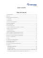
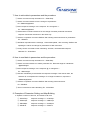
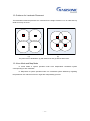
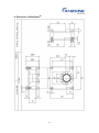
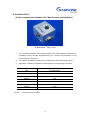
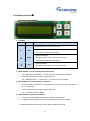
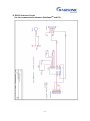
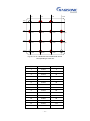
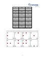
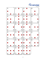
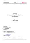
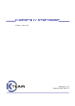
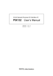
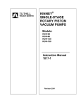
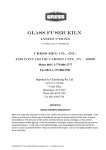
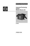
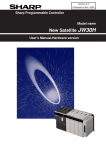
User’s Guide Localization system StarGazerTM for Intelligent Robots www.hagisonic.com User’s Guide Table of Contents 1. Product Overview ------------------------------------------------------------------------------------------------- 2 2. Parts List ------------------------------------------------------------------------------------------------ ------------ 3 3. Product Feature and Specification --------------------------------------------------------------------------- 3 A. Landmarks ------------------------------------------------------------------------------------------------------ 3 B. Specification ---------------------------------------------------------------------------------------------------- 4 C. Features and Performance ----------------------------------------------------------------------------- 4 4. Connector Configuration ---------------------------------------------------------------------------------------- 5 5. UART Configuration ---------------------------------------------------------------------------------------------- 5 6. Communication Protocol ---------------------------------------------------------------------------------------- 5 A. Communication Protocol, Parameters, Commands -------------------------------------------------- 5 B. Basic Command and Protocol ----------------------------------------------------------------------------- 6 C. About Parameters --------------------------------------------------------------------------------------------- 6 D. Execution Commands ---------------------------------------------------------------------------------------- 7 7. How to write data to parameters and the procedure ----------------------------------------------------- 8 8. How to read data in parameters and the procedure ----------------------------------------------------- 8 9. Examples of Parameter Setting and Map-Building ------------------------------------------------------ 8 10. Format of Received Data ------------------------------------------------------------------------------------ 9 11. Notice ------------------------------------------------------------------------------------------------------------- 10 12. Guidance for Landmark Placement ----------------------------------------------------------------------- 11 13. Alone Mode and Map Mode -------------------------------------------------------------------------------- 11 14. Map-Building Method ----------------------------------------------------------------------------------------- 12 15. Inquiries for technical Information and A/S ------------------------------------------------------------- 12 16. Appendix --------------------------------------------------------------------------------------------------------- 12 A. Dimension of StarGazer™ ----------------------------------------------------------------------------- 13 B. StarGazer RS1.0 ------------------------------------------------------------------------------------------ 14 C. StarGazer Indicator™ ----------------------------------------------------------------------------------- 15 D. RS232 Interface Circuit (for the communication between StarGazer and PC / MainProcess)-- 16 E. The types of landmarks and how to generate the number of ID ------------------------------ 17 -1- 1. Product Overview StarGazer™ is a unique sensor system for Indoor localization of intelligent mobile robots. It analyzes infrared ray image which is reflected from a passive landmark with an independent ID. The output of position and heading angle of a robot is given with very precise resolution and high speed. It is seldom affected by surroundings such as an infrared ray, a fluorescent light and sunshine. An illustration showing how StarGazer StarGazer™ TM works. Passive Landmarks -2- 2. Parts List A. StarGazer Module (DSP Module, IRED Module, Support, Lens Hood) - 1set B. 3pin Connector with cables - 1ea, 7pin Connector with cables - 1ea C. Passive Landmarks - 4ea D. User’s Manual (Download from website www.hagisonic.com.) E. Sample Program with Visual C++ 6.0(Download from website www.hagisonic.com.) 3. Features and Specification A. Landmarks - With IDs i.e. codes given by the combination of circles to reflect infrared rays - No battery or adapter for Landmark is required. - Easy extension of application range - Landmark Types by use (1) HLD1: 3 X 3 combination, total 31ea, for normal use HLD1-1: 0.3 m ≤ Height ≤ 1.1 m HLD1-2: 1.1 m ≤ Height ≤ 2.9 m HLD1-3: 2.9 m ≤ Height ≤ 4.5 m HLD1-4: 4.5 m ≤ Height ≤ 6.5 m HLD1-5: 6.5 m ≤ Height ≤ 15 m (2) HLD2: 4 X 4 combination, total 4,095ea, for larger spaces HLD2-1: 0.3 m ≤ Height ≤ 1.1 m HLD2-2: 1.1 m ≤ Height ≤ 2.9 m HLD2-3: 2.9 m ≤ Height ≤ 4.5 m HLD2-4: 4.5 m ≤ Height ≤ 6.5 m HLD2-5: 6.5 m ≤ Height ≤ 15 m ※ ‘Height’ means the distance between a StarGazer between a landmark which is attached on ceiling. ※ Please refer to [12. Appendix D. for the detailed information about landmark] -3- B. Specification of StarGazer™ Hardware Interface UART(TTL 3.3V), 115,200bps Size 50×50×28mm Communication Protocol User protocol based on ASCII code Measurement Time 20 times/sec Localization Rang 2.5~5 m in diameter (per a Landmark) (for ceiling height 2~6 m) Repetitive Precision 2 cm Heading Angle Resolution 1.0degree Type 1: 0.3 ≤ height ≤ 1.1 m Landmark Types Type 2: 1.1 ≤ height ≤ 2.9 m (Classification for height range) Type 4: 4.5 ≤ height ≤ 6.5 m Type 3: 2.9 ≤ height ≤ 4.5 m Type 5: 6.5 ≤ height ≤ 15 m Landmark Types HL1: 31 ea (for a normal space) (Classification for total ID numbers) HL2: 4,095 ea (for a larger space) Power Consumption 5 V: 300 mA, 12 V: 70 mA C. Features and Performance - It analyzes the image of the infrared ray which is reflected from a passive landmark with a unique ID. - It is composed of an IR Projector part and an image processing unit. - High resolution and high speed localization of position and heading angle. - Landmark is used by being attached on ceiling. - No need for any synchronization or communication between a robot and a landmark. - The area that StarGazer covers is extended by only adding landmarks to ceiling. - Each room can be distinguished easily each other by using landmarks with different IDs. - Automatic measurement and calibration of distance between landmarks and ceiling height. - No battery or power supply for landmark is needed. - A little extra cost consumes when landmarks are attached additionally. - Nearly not affected in environment such as lamp and sunlight - It works excellent localization function at night as well as in the day. -4- - World’s best in resolution, convenience and cost-efficiency 4. Connector Configuration ① Connector configuration for DSP Module Cable Line White Black White Black Reserved GND SDIN GND Color Function White Red Red SDOUT VCC(5V) VCC(5V) ② Connector configuration for IRED Module Cable Color Black White Yellow Function GND Reserved VCC(12V) 5. UART Configuration The StarGazer supports UART communication as shown in Table 1. Table. 1. UART configuration I/O Level TTL 3.3V Output, 3.3V~5V Input Baudrate 115200 bps Data Bit 8bit Stop Bit 1bit Paraty Bit None Flow Control None 6. Communication Protocol StarGazer calculates coordinates and heading angle using parameters in flash memory. The protocols, shown in Table 2 and Table 3, can be used to read or update the parameters. A. Communication Protocol, Parameters, Commands Table. 2. Communication Protocols Read STX @ Command ETX Write STX # Command | Data ETX Return Value STX $ Command | Data ETX ACK STX ! Command | Data ETX ※ Notice: STX: '~', ETX: '`' -5- Table. 3. Parameters and commands Parameters and Command ThrAlg Threshold Algorithm(Auto/Manual) ThrVal Threshold Value(0-255) MarkType Mark Type(Home/Office) MapMode Map Building Mode(Start/Stop) MarkMode Landmark Mode(Alone/Map) MarkDim Landmark Deimension(HLDn-m) MarkHeight HeightCalc * Height of Landmark(mm) Calculate Height of Landmark IDNum Number of ID(1-31, 1-4095) RefID Reference ID(2-626, 2-28662) Version Firmware Version * Calculation Start * Calculation Stop CalcStart CalcStop SetEnd * Reset Parameter Setting End Reset All Parameter B. Basic Command and Protocol ~: to mean the start of command sentence; STX(start of text) character. `: to mean the end of command sentence; ETX(end of text) character. @: to mean command to read a following parameter; READ command !: to follow automatically when READ or WRITE command completely executed; ACK(acknowledge) character. Response symbol sent from a StarGazer. $: Response symbol to mean that data follow after the following parameter as response of READ command. |: Symbol to distinguish a command from data Or to distinguish Parameter from data C. About Parameters (1) Parameters for data Parameters: ThrVal, MarkHeight, IDNum, RefID, Version ThrVal: Threshold level to reject external turbulence shown in image; depend on surroundings. Default number is 210. Recommended value is ranging from 210 to 240. MarkHeight: Distance from a StarGazer to a landmark; used when wanting to input manually the height; Default value: 2400 mm IDNum: A total number of landmarks to be assigned under Map Mode. Default value: 4 RefID: The number of reference ID under Map Mode; Default value: 2 Version: Version of Firmware. -6- (2) Parameters for setting up modes - Parameters: ThrAlg, MarkType, MapMode, MarkMode ThrAlg: To determine how to get ThrVal; There are Auto and Manual. ‘Manual’ should be assigned to use the input data and ‘Auto’ be assigned to use a value calculated automatically in StarGazer. Default: Manual. MarkType: To set up landmark type by use. There are Home and Office. Home means HL1-1 landmark(up to 31 IDs) and Office means HL2-1(up to 4095 IDs). Default: Home. MarkDim: To set up landmark type by height. There are different landmark types for height - HLDn-2 for MarkDim 1, HLDn-3 for MarkDim 2, HLDn-4 for MarkDim 3. MapMode: To determine whether map building mode is executed or not. There are Start and Stop. If action under Map Mode is required, you should set the parameter ‘Start’ and start Map Building. Default; Stop MarkMode: To determine whether landmarks are used independently under Alone Mode or not (dependently under Map Mode). There are Alone and Map. Default; Alone (if Map mode, then ‘Map’.) D. Execution Commands - Commands: HeightCalc, CalcStart, CalcStop, SetEnd HeightCalc: Command to calculate automatically height between a StarGazer and a landmark. It is enough to execute only once when installing. CalcStart: Command to start calculation. After executing the command, the output of data including position and angle is obtained continuously. CalcStop: Command to stop calculating. SetEnd: Command to mean the completion of a serious of command sentences. Values for a serious of parameters given in preceding several commend sentences are operated only after ‘SetEnd’ command comes into practice. ※ Note: Execution command ‘HeightCalc’, ‘CalcStart’, ‘CalcStop’ are operated without ‘SetEnd’ and also ‘MapMode’ and ‘Version’ of parameters are operated without ‘SetEnd’ too. Reset: Reset all the parameters. Following is parameters that are reset. ThrVal = 210 MarkType = Home IDMultipleType = Alone IDNum = 4 MarkDim = 1 RefID = 2 MarkHeight = 2400 -7- 7. How to write data to parameters and the procedure ① Send a command to stop calculation. Ex. ~#CalcStop` ② Send a command sentence for the change of a parameter. Ex. ~#MarkHeight|2200` ③ Wait a response message. In the response ‘#’ is changed to ‘!’. Ex. ~!MarkHeight|2200` ④ Send another command sentence for the change of another parameter and wait a response. Send other sentences in the same way. ⑤ Send the completion command ‘SetEnd’ after sending whole sentences for parameters. Ex. ~#SetEnd` ⑥ StarGazer responds with the message, ~!ParameterUpdate`, after receiving ‘SetEnd’ and updating the values and strings for parameters to flash memories. ⑦ Finally, send a command to start calculating. And then, calculated data output is obtained. Ex. ~#CalcStart` 8. How to read data in parameters and the procedure ① Send a command to stop calculation. Ex. ~#CalcStop` ② Send a command sentence to read a parameter. Ex. Read the height of a landmark: ~@MarkHeight` ③ Wait a response message. In the response ‘@’ is changed to ‘!’. Ex. ~!MarkHeight` ④ Data are immediately received after the response message. If the data is value, the character ‘$’ accompanies the message. Ex. If height is 2200 mm, response is ~$MarkHeight|2200` ⑤ Send the completion command ‘SetEnd’ after sending whole sentences. Ex. ~#SetEnd` ⑥ Send a command to start calculating. Ex. ~#CalcStart` 9. Examples of Parameter Setting and Map-Building A. Update a number of IDs to 8, and reference ID to 32 ① ~#CalcStop` response message => ~!CalcStop` ② ~#IDNum|8` response message => ~!IDNum|8` ③ ~#RefID|32` response message => ~!RefID|32` ④ ~#SetEnd` response message => ~!SetEnd` -8- response message => ~!ParameterUpdate` ⑤ ~#CalcStart` response message => ~!CalcStart` B. Calculate automatically the height of a landmark ① ~#CalcStop` response message => ~!CalcStop` ② ~#HeightCalc` response message => ~!HeightCalc` ③ The data received during calculating ~^Z+150.12|-33.12|+12.00|2 [Refer to 7. Receiving Data Format] ④ The reponse received after the completion of calculation; ~!ParameterUpdate` ⑤ ~#CalcStart` response message => ~!CalcStart` C. Start the Map-Building Process and the message ① ~#CalcStop` response message => ~!CalcStop` ② ~#MarkMode|Map` response message => ~!MarkMode|Map` ③ ~#MapMode|Start` response message => ~!MapMode|Start` ④ ~#CalcStart` response message => ~!CalcStart` ⑤ The data received during Map-Building process ~^F-165.74|-33.12|+12.00|2 [Refer to 7. Receiving Data Format] ⑥ Move StarGazer around landmarks until mapping is completed. ⑦ After the completion of mapping the response message is accompanied by ~!ParameterUpdate` ⑧ Then, receiving data is as follows: ~^I+58.48|-33.12|+12.00|2 [Refer to 7. Receiving Data Format] 10. Format of Received Data The format of data received from StarGazer for the command ~#CalcStart` are as follows: F ~ ^ I ±aaaa.aa|±xxxx.xx|±yyyy.yy|iiii Z ^ Means the result data F Indicates the Map-Building Mode I Indicates the Map Mode Z Indicates the Height Calculation Mode ±aaaa.aa Value of Angle (degrees; -180˚~+180˚) -9- ` ±xxxx.xx Position on X axis (cm) ±yyyy.yy Position on Y axis (cm) Iiii The number of an ID Ex. ~^I+150.23|-33.12|+12.00|64` ~^I+36.73|-174.89|+57.00|64` ※ Map-building mode: a mode in the process of making a map by correlating several landmarks under a single coordinate system. In the process StarGazer is moved around under each landmark and correlation between landmarks is calculated. ※ Map mode: the mode to calculate the position and angle of StarGazer and send the data using the Map after the completion of Map-Building. 11. Notice ① Though it can be possible to send or receive data without the command, ‘stop calculation’, in that case sometimes the command cannot operate because StarGazer is sending data successively. Therefore, it is strongly recommended to use the command ‘stop calculation’, prior to other command sentences. ② Sometimes, the command ‘stop calculation’ can be executed because of the same reason that a command is not executed though a command has been sent, the command should be sent repeatedly. ③ In order to communicate stably with StarGazer, minimum 50 ms delay is required for every byte. ④ The program should be written to confirm the response message for each command. ⑤ When StarGazer updates a memory, several seconds, typically two or three seconds, is required. So, after a command such as [SetEnd] or [HeightCalc] or after the completion of Map-Building, StarGazer cannot operate. Note that [~!ParameterUpdate`] message is shown after the completion of a memory update. ⑥ StarGazer operates only over 1.2m height. ⑦ Map-Building should be programmed by the procedure to be shown in [9. C. Start the Map-Building Process and the message] - 10 - 12. Guidance for Landmark Placement The landmarks should be placed at 2 m intervals for the height of about 2.5 m in order that any dead zone may not occur. (a) (b) The placement of landmarks: (a) with dead zone and (b) without dead zone. 13. Alone Mode and Map Mode In ‘Alone Mode’ a system operates under each independent coordinate system corresponding to each landmark. In ‘Map Mode’ a system operates under one coordinate system defined by regarding the placement of a reference ID as an origin after map-building process. - 11 - 14. Map-Building Method 1) Map-building: to make a map under single coordinate system. The placement of a reference ID becomes an origin. 2) Set ‘MarkMode’ to ‘Map’ and ‘MapMode’ to ‘start’. 3) If StarGazer detects a landmark, a position data accompanied by ‘~^F” is responded. 4) As the next step, move toward other nearest landmark and stop for about two seconds near halfway between two landmarks for the time to calculate the relation. 5) And then, move toward other landmark and stop near midway between another landmarks. 6) Proceed by the same way until whole landmarks are detected by StarGazer. 7) If the last landmark is found, the operating is stopped for a short time for data updating to flash memory. 8) Then, a response message, data message accompanied by ‘~I^’ is given and mapbuilding process ends. 9) Mode is automatically changed to ‘Map Mode’. ※ For example and some details, refer to [9. C. Start the Map-Building Process and the message] 15. Inquiries for Technical Support and Customer Service HAGISONIC Co., LTD TEL: +82-42-936-7740 FAX: +82-42-936-7742 Address: 535 Yongsan-dong, Yuseong-gu, Daejeon 305-500, Korea (South) Website: www.hagisonic.com Email : [email protected] 16. Appendix A. Product Dimension B. RS232 Interface Circuit (for the communication between StarGazer and PC) C. The types of landmarks and how to generate the number of ID. - 12 - A. Dimension of StarGazerTM - 13 - B. StarGazer RS1.0 (for the communication between PC, Main Process and StarGazer) (a) StarGazerTM RS 1.0 Kit 1. The user-friendly solution which easily outputs and controls data from StarGazer™, localization sensor, through standard serial wire / wireless communication in PCs, various systems, and robots 2. The optimum localization system which is registered to Microsoft Robotics Studio. 3. Application : Research in laboratory and development of the prototype of robots. I/O Level TTL 3.3V Output, 3.3V~5V Input Size 62×56×50.8mm Power DC 12V Baud Rate 115200 bps Data Bit 8 Bit Stop Bit 1 Bit Parity Bit None Flow Bit None ※ Output : ~^I+150.23|-33.12|+12.00|64` - 14 - C. StarGazer Indicator™ 1. Control Initial Name M Menu E Enter Description Menu Button: to move to other menu. Selection Button : to select the menu. Also used to remove Buzzer sound. Right Scroll Button ▶ Right After Menu button, users can scroll to the right. Also, users can select Buzzer sound. ◀ Left Left Scroll Button After Menu button, users can scroll to the left. 1) Mode Number 1: Pure Communication data mode The output data of StarGazer™ is shown on the LCD without any filtration. Users can see data by using the right or left scroll. Ex) ~*CMOS|Success` , ~*Dead zone`, ~^I+150.23|-33.12|+12.00|64` 2) Mode Number 2: Communication information The output data of StarGazer™ is filtered and is shown on the LCD in the order of ID, X, Y and Angle. Users can see data by using the right or left scroll. Ex) ~^I+150.23|-33.12|+12.00|64` 3) Mode Number 3: System information Users can see the default communication setting of StarGazer™. In addition, pressing button one more time allows users to set up Buzzer. ※ After Buzzer setup, please push the Enter button to finish the setting. - 15 - D. RS232 Interface Circuit (for the communication between StarGazerTM and PC) - 16 - E. Types of landmarks and how to generate the number of ID (1) HLD1 landmarks are composed of the 3 X 3 combination of small circles. The total number is 31. The landmarks are used for general application such as at home. (2) HLD2 landmarks are composed of the 4 X 4 combination of small circles. The total number is 4095. The landmarks are used for the application to very large area with several offices. (3) Each line corresponds to an identified hexadecimal value. (4) Fig.16-C-3 shows HL1 landmarks and corresponding decimal values. ※ ‘0x’in figures is the notation to mean hexadecimal. 0x01 0x10 0x100 0x01 0x10 0x02 0x02 0x20 0x200 0x04 0x40 Fig.16-C-1. HL1 landmark with hexadecimal values corresponding to each line. - 17 - 0x01 0x10 0x1000 0x100 0x01 0x01 0x10 0x100 0x02 0x20 0x200 0x2000 0x04 0x40 0x400 0x4000 0x08 0x80 0x800 0x02 0x04 0x08 Fig.16-C-2. HL2 landmark with hexadecimal values corresponding to each line. 번호 HEX DEC 1 0x002 2 2 0x010 16 3 0x012 18 4 0x020 32 5 0x022 34 6 0x030 48 7 0x032 50 8 0x040 64 9 0x042 68 10 0x050 80 11 0x052 82 12 0x060 96 13 0x062 98 14 0x070 112 15 0x072 114 - 18 - 16 0x200 512 17 0x202 514 18 0x210 528 19 0x212 530 20 0x220 544 21 0x222 546 22 0x230 560 23 0x232 562 24 0x240 576 25 0x242 578 26 0x250 592 27 0x252 594 28 0x260 608 29 0x262 610 30 0x270 624 31 0x272 626 Fig.16-C-3. Showing HL1 landmarks and ID numbers. Fig.16-C-4. Type of the HL1 landmark(decimal number inside the landmark means a ID number) 2 16 18 32 34 48 50 64 - 19 - 68 80 82 96 98 112 114 512 514 528 530 544 546 560 562 576 578 592 594 608 610 624 626 - 20 -