1
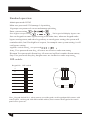
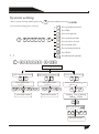
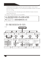
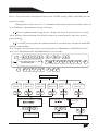
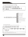
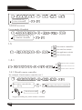
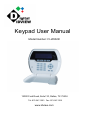
Keypad User Manual Model Number: IV-IA502R 12000 Ford Road, Suite110, Dallas, TX 75234 Tel: 972-247-1203 Fax: 972-247-1291 www.idview.com Content Keypad instruction System setting 1.1 Set password 1.2 Set CMS 1.3 Set voice phone 1.4 Set system options 1.4.1 Set system clock 1.4.2 Set enter delay time 1.4.3 Set exit delay time 1.4.4 Set siren time 1.4.5 Set ring times 1.4.6 Set sensor loss inspection 1.4.7 Set phone line inspection 1.4.8 Set AC off delay report 1.4.9 Set emergency alarm remindt 1.4.0Set more 1.4.9.1Arm/disarm report 1.4.9.2 Door contact inspection 1.4.9.3Chenk wireless detector tamper 1.4.9.4Arm/disarm tone 1.4.9.5Force arm 1.5Manage wireless device 1 3 3 4 5 6 6 7 7 7 7 8 8 8 8 9 9 9 9 9 10 10 1.5.1Set remote controller 1.5.1.1Enroll remote controller 10 10 1.5.1.2Enter remote controller code 1.5.1.3Delete remote controller 1.5.2Set detector 1.5.2.1Enroll detector 1.5.2.2Enter detector code 1.5.2.3Delete detector 1.5.3Set appliance switch 11 11 11 11 11 12 12 1.5.3.1Enroll appliance switch 1.5.3.2Enter appliance switch code 1.5.3.3Delete appliance switch 1.5.4Set wireless siren 1.5.4.1Enroll wireless siren 1.5.4.2Delete wireless siren 1.6Set zone 1.6.1Set zone type 1.6.2Set zone siren 1.6.3Set related zone 1.6.4Set alarm limit 1.7Set system partition 12 12 12 13 13 13 13 13 14 14 15 15 1.7.1Set zone 15 1.7.2Set keypad 15 1.7.3Set remote controller 15 1.7.4Set voice phone 1.8Set GSM 15 16 1.7.1Enable/disable GSM 16 1.7.2Enable/disable GPRS 16 6.7.3 Set GPRS 16 6.7.4 GPRS alarm receiving service 16 6.7.5GPRS register info 1.9Set advanced options 17 17 Keypad instruction Disarm Arm Partition Home Power LED Trouble LED Arm LED Disarm LED Key direction The number key Confirm key Delete Exit LED Power:AC off slow flash, light on when no trouble Trouble:Light on when zone trouble, light off when no trouble Arm:Light off under disarmed,light flash slowly under stay, light on under armed status Disarm: Light on under disarmed status, light off under stay and armed status Key function: Arm The system can be armed different partitions UP via keypad at the same time Down, Inquiry event logs under Stay The system can be stayed different partitions standby mode via keypad at the same time Left, can set bypass zone under standby mode Disarm The system can be disarmed different partitions via keypad at the same time Right, control appliance switch Set key Set key Exit Set key Delete Set key 1 Standard operation: Admin password:012345 Main user password:1234,manage 1-4 partition 16 groups user password: can set and manage partition Enter system setting Zone bypass:user password The keypad will display bypass zone. Just one keypad can enter bypass setting at the same time, when one keypad under bypass setting status, and other keypads try to enter bypass setting, the system will remind trouble, but if for high level request, for example enter system setting, it will exit bypass setting Appliance switch control user password Arm User password+arm key all zones are effective under arm status Disarm User password+disarm key, all zones are ineffective under disarm status Stay:User password+Stay key, burglar zones are ineffective under stay status DIP switch: Keypad No. DIP switch ON 1 1 2 3 4 2 3 4 2 3 4 2 3 4 2 3 4 2 3 4 Wiring port ON 2 1 ON 3 1 ON 4 1 Wiring port ON 5 1 ON 6 1 7 1 ON Tamper ON 2 3 4 2 3 4 DIP switch 1 2 3 4 ON 8 1 Note Keypad default No.1, when connect several keypads, each keypad parallel connect with control panel, each keypad with different DIP address, must connect the keypad with control panel before power on . 2 System setting # Enter system setting: admin password Default admin passwrd Exit system setting: press exit key 0 1 2 3 4 5 * # 1.1 Ï µ Í ³ Ã Ü Â ë É è Ö Ã * 0 1 2 3 4 5 # 1 2 3 4 5 6 7 8 Set system password 9 Set advanced options Set CMS Set voice phone Set system options Set wireless device Set system zone Set system partition Set GSM 1 # Set system password [1]Set admin passwrod 1 [2]Set main user password # Enter passwrod ****** X X X X X X # Auto return to menu 2 # Enter password ****** X X X X # Auto return to menu [3]Set user passwrod 3 # Enter password No. 01 01-16 0 1 # Partiton 1234 *Select Manage YNNN * # Enter password X X X X # Auto return to menu 3 1.Admin password is 6 digits, main user password is 4 digits, can set 16 user password, the password No.:01-16, but the password Number from 02-16 can not enter user setting 2.If forgot the password, the admin password is 000000 in 1 minute when the control panel power on For example: change admin password to 888888 0 1 2 3 4 5 Enter password ****** * # 1 # 8 8 8 8 8 8 0 1 2 3 4 5 # 1 # # 2 # 1.2 ½ Ó ¾ ¯ Ö Ð Ð Ä É è Ö Ã Set CMS [1]Set CMS No.1 1 # [2]Set CMS [3]Set User No.2 No. 2 # Enter phone number X X X X X X X X X X X # Auto return to menu 4 3 # Enter user No. X X X X # [4]Set dialing times 4 # Enter dialing times X X # [5]Set CMS communication [6]Set priority inspection interval time in transmission 5 # Enter communcation inspection interval time 000 0-999 h 0 disabled X X X # Auto return to menu Auto return to menu Auto return to menu 6 # Priority in transmission:1 1Phone line 2GSM X # Auto return to menu Note: 1.The user code is the identification code in CMS setting,CMS1 and CMS2 use the same user code Dialing times can be set as 1-15, communication inspection interval time can be set as 0-999hours, the common setting is 24 hours. When set phone number,long press 1, display the letter P, means pause 1 second when dialing, when the phone line which connect to control panel is sub-line, need a pause dialing For GSM, just recognize the number behind P, can make sure telephone and GSM dial the same number For example: the sub-line connect to control panel, CMS number is 80808080, in this way, set CMS number like this9P80808080, 9 is out code. 0 1 2 3 4 5 * # 2 # 1.3 Ó ïEnter Ò phone ô µ number ç » ° ÉP è Ö9 à 00000000000 * 0 1 2 3 4 5 # 1 # 8 0 8 0 8 0 8 0 # 3 # Set voice phone [1]Set voice [2]Set voice phone 1 phone 2 1 # [3]Set voice phone 3 2 # 3 # [4]Set voice [5]Set dialing phone 4 times 4 # 5 # Enter phone number Enter dialing times X X X # X X # [6]Set calling priority 6 # Select calling priority Phone line GSM X Auto return to menu # Auto return to menu Auto return to menu 5 Note 1.The dialing times can be set as 1-15 times For example: Set voice phone number 3 as 12345678 0 1 2 3 4 5 * # Enter phone number 3 # 3 # 1 2 3 4 5 6 7 8 # 1.4 Ï µ Í ³ Ñ ¡ Ï î É è Ö Ã * 0 1 2 3 4 5 # 4 # 1 2 3 4 5 6 7 8 9 0 Set system clock Set entry delay Set exit delay Set siren time Set ring times Set sensor loss inspection Set phone line inspection Set AC off delay report Set emergency alarm remind Set more 1.4.1 Set system clock For example: Set system clock to 22:59:36 22/12/2013 * 0 1 2 3 4 5 Enter system clock 3 6 # 4 # 1 # 1 3 1 2 2 2 2 2 Y M D H 5 9 Min # Secretary According to flash of Y.M.D.H.Min.Sec on screen , enter 13.12.22.22.59.36 by turn also can press [UP] [DOWN] key to move cursor. 6 1.4.2 Set entry delay: when trigger alarm, the panel will give delay time( default setting is 10s) For example: set entry delay time as 20s * 0 1 2 3 4 5 Enter delay time 010 # 4 # 0 2 0 2 # # Note:Entry delay is just effective for delay zone, other zone type can not enter delay 1.4.3 Set exit delay time: after user armed the system,it is convenient for user to exit the area after arm successfully,(the default setting is 10s) For example: Set exit delay time as 20s 0 1 2 3 4 5 * Enter delay time 001 s # 4 # 0 2 0 3 # # 1.4.4 Set siren time:The siren ring time after alarm is triggered(the default setting is 5 minutes) For example: Set siren time as 10 minutes 0 1 2 3 4 5 * Set siren time 10 01-30 M # 4 # 1 0 # 4 # 1.4.5 Set ring times:User remote control alarm panel, dial the preset phone number , the panel will off-hook after phone ring times(the default setting is 7 times) For example: Set ring times as 5 * 0 1 2 3 4 5 Enter ring times 05 00-15 0 is disabled # 4 # 0 5 5 # # 7 1 .4.6 Set sensor loss inspection: the alarm panel will inspect the sensors’ status or alarm info in this time interval, if not receive, it is determined that the sensor is loss,the general setting is not less than 8 hours.(the default setting is 0 ,disabled this function) For example: Set sensor loss inspection time as 8 hours 0 1 2 3 4 5 * # 4 # Enter sensor loss inspection time:08 0-99 h 0 disabled 6 # 0 8 # 1.4.7 Set phone line inspection For example: set phone line inspection * 0 1 2 3 4 5 Phone line inspection 1 1. alarm2. remind3.disabled # 4 # 1 # 7 # 1.4.8 Set AC off delay report: when AC power is off, delay report to CMS (the default setting is 30 minutes) For example: Set AC off inspection time as 15 minutes * 0 1 2 3 4 5 # 4 # Enter AC off delay time 015 0-999 Min 0 disabled 8 # 0 1 5 1.4.9 Set emergency alarm remind For example: Set emergency alarm remind as siren tone * 0 1 2 3 4 5 Select emergency alarm remind:1 1. Siren 2. Mute 8 # 4 # 1 # 9 # # 1.4.0¸ü¶àÉèÖ㺠0 1 2 3 4 5 * # 4 # 1 2 3 4 5 0 # 1.4.0.1Arm/disarm report Arm/disarm report Door contact inspection Wireless detector tamper inspection Arm/disarm tone Force arm For example: Set arm/disarm report to CMS * 0 1 2 3 4 5 Pls choose arm/disarm report:1 1. Enable 2. Disable # 4 # 1 # 0 # 1 # 1.4.0.2 Door contact inspection: set if the control panel show zone trouble on LCD screen or not when separate the magnetic strip from transmitter (the default setting is disabled) For example: Enabled door contact inspection * 0 1 2 3 4 5 Door contact inspection:1 1. Enabled 2. Disabled # 1 4 # 0 # 2 # # 1.4.0.3Wireless sensor tamper inspection: if enabled, when trigger the sensor tamper, will trigger the alarm, if disabled, it will not trigger the alarm (The default setting is enabled) For example: Disabled wireless sensor tamper inspection * 0 1 2 3 4 5 Wireless sensor tamper inspection:2 1. Enabled 2. Disabled # 4 # 2 0 # 3 # # 1.4.0.4 Arm/disarm tone For example: set arm/disarm remind as siren tone 9 * # 0 1 2 3 4 5 Arm/disarm tone 1 1.Siren 2.Disabled 4 # 0 # 4 # 4 # 0 # 5 # 5 # 1 2 3 4 # 1 1.4.0.5 Force arm For example: Disabled * 0 1 2 3 4 5 # Zone fault force arm 2 1.Enabled 2.Disabled 2 # 1.5Î Þ Ï ß É è ± ¸ ¹ Ü À í 0 1 2 3 4 5 * # Set remote contorller Set wireless sensor Set appliance switch Set wireless siren 1.5.1Î Þ Ï ß Ò £ ¿ Ø Æ ÷ ¹ Ü À í 0 1 2 3 4 5 * 5 # # 1 # 1 2 3 Enroll remote controller Enter remote controller code Delete remote controller 1.5.1.1Enroll remote controller For example: Enroll remote controller to # 3 * 0 1 2 3 4 5 Enter remote controller No. 1-8 3 # 3 Enroll successfull 5 # # # Trigger the arming key on the remote controller. 10 1 # 1 # Pls trigger the remote controller 1.5.1.2Enter remote controller code For example: Manual enter remote controller code 112113114 to #8 remote controoler 0 1 2 3 4 5 # 5 # Enter remote controller No.:8 1-8 8 # * 1 1 2 1 1 3 1 1 4 1 # 2 # Enter remote controller code # 1.5.1.3Delete remote controller For example: Delete #5 remote controller 0 1 2 3 4 5 * 5 # # Enter the Number of remote controller to delete:5 1-8 0 delete all 5 1 # # 3 # Pls confirm to delete wireless devide # 1.5.2Î Þ Ï ß Ì ½ ² â Æ ÷ ¹ Ü À í 0 1 2 3 4 5 * 5 # # 1 2 3 2 # 1.5.2.1Enroll wireless detector Enroll wireless detector Enter detector code Delete detector For example: Auto enroll detector code to #9 detector * 0 1 2 3 4 5 Enter detector No.:09 01-32 # 5 # 0 9 # 2 # 1 # Pls trigger wireless devide # Pls confirm the device code 1.5.2.2Enter detector code For example: Manual enter detector code 011055033 to #7 detector * 0 1 2 3 4 5 Enter detector No.:07 01-32 # 0 7 0 1 1 0 2 2 0 3 3 5 # # 2 # 2 # Pls enter device code # 11 1.5.2.3Delete detector For example: delete #3 detector * 0 1 2 3 4 5 # 5 # Enter the number of detector to delete:03 01-32 0 delete all 0 3 3 # 2 # Pls confirm to delete wireless devide # # 1.5.3µ ç Æ ÷ ¿ ª ¹ Ø ¹ Ü À í 0 1 2 3 4 5 * 5 # # 3 # 1 Enroll appliance switch 2 3 Enter appliance switch code Delete appliance switch 1.5.3.1Enroll appliance siwtch For example: Enroll appliance switch to #1 switch * 0 1 2 3 4 5 Enter appliance switch No.:01 5 # # # 0 1 3 # Trigger appliance switch 1 # Enroll successful # 1.5.3.2 Enter appliance switch code For example: Manual enter appliance switch to #1 switch * 0 1 2 3 4 5 5 # # Enter appliance switch No.:01 01-16 0 1 1 7 7 0 0 5 0 0 5 3 # # 2 # Enter appliance switch code # 1.5.3.3 Delete appliance switch For example: Delete #4 appliance switch * 0 1 2 3 4 5 # Enter the number of switch to delete:04 01-16 0 delete all 12 5 # 0 4 3 # # 3 # Pls confirm to delete wireless device # 1.5.4Î Þ Ï ß ¾ ¯ º Å ¶ Ô Â ë 0 1 2 3 4 5 * 5 # # 1 2 4 # Enroll wireless siren Delete wireless siren 1.5.4.1 Enroll wireless siren 0 1 2 3 4 5 * 5 # # Pls make wireless siren under coding status,press confirm key to start coding Coding 1 # 4 # # 1-way wireless siren If 2-way wireless siren, the LCD screen will display the code of wiren Note:When 2-way wireless siren make tamper alarm, the keypad will display Zone 41 one panel just can enroll 1pcs 2-way siren, for 1-way siren, no limit. 1.5.4.2Delete wireless siren * 0 1 2 3 4 5 Pls confirm to delete 2-way siren # 5 # 4 # 2 # # Note: It is 2-way wireless siren to delete 1.6Ï µ Í ³ · À Ç ø É è Ö Ã * 0 1 2 3 4 5 # 1.6.1 Set zone attribution 6 # 1 2 3 4 Set zone attribution Set zone siren Set related zone Set alarm limit The type of zone attribution is as below: Disable zone Delay zone Perimeter zone Interior zone Emergency zone 24 hours zone Fire zone Zone attribution is the alarm type of the zone display on the keypad when the zone is triggered. When set zone attribution as 0 is to disable the zone, the panel will not make alarm when trigger this zone Interior zone only trigger alarm when the system under arm status. Delay and perimeter zone trigger alarm when the system under stay or arm status Emergency, 24 hours ,fire zone will trigger the alarm when the system at any status 13 Factory default setting: Wireless zone 1-32 enable, wired zone 33-40 disable, 41 is for wireless 2-way siren For example: Set zone 39 as perimeter zone 0 1 2 3 4 5 * Enter zone No.:039 001-112 7 # 0 3 9 6 # # 1 # Pls choose zone type: 0 disable the zone 1.Delay zone 2. Perimeter zone 3. Interior zone 4. Emergency zone 5. 24 hours zone 6.Fire zone # 1.6.2 Set zone siren(the default setting is pedal point) For example: Set zone 23 siren type as mute * 0 1 2 3 4 5 Enter zone No.:023 001-112 # 0 2 3 6 # # 2 # Pls choose siren type:2 1.pedal point 2.mute 2 # 1.6.3 Set related zone Trigger the related zone 1,2 separately will not trigger alarm, during the related time trigger zone 1 and 2, then the related zone 1 and 2 will make alarm For example: set zone 5 and zone 9 as group 4 dual trigger mode related zone the related time is 120sec. * 0 1 2 3 4 5 Enter group No.:3 1-8 # 14 3 Enter related zone 1 000 000-112 0 disabled 0 0 5 1 2 0 # 6 # # # 5 # Enter related zone 1 000 000-112 0 disabled 0 0 5 # 0 0 5 Enter related time 000 000-255 sec 1.6.4 Set alarm limit For example: Set as unlimit * 0 1 2 3 4 5 # Pls choose alarm limit 2 1.bypass after 3 times2.unlimit 6 # 4 # # 2 1.7Ï µ Í ³ · Ö Ç ø É è Ö Ã * 0 1 2 3 4 5 1 2 3 4 7 # # Set partition zone Set partition keypad Set partition remote controller Set partition voice phone 1.7.1 Set partition zone For example: Set 001 zone belong to partition 1 * 0 1 2 3 4 5 Enter zone No. 001 000-112 # 0 0 1 7 # 1 # Partiton 1234 Zone YNNN # *Select * # Note: Total 4 partitions 1.7.2 Set partition keypad For example: Set keypad 1 belong to partition 2 * 0 1 2 3 4 5 Enter keypad No.:1 (1-8) 1 # 7 # 2 # Partition 1234 *select Keypad NYNN # # * 1.7.3 Set partition remote controller For example: Set remote controller 1 belong to partition 3 * 0 1 2 3 4 5 Enter remote controllre No.:1 1-8 1 # # 7 # 3 # Partition 1234 *select Remote controller NNYN * * # 1.7.4 Set partition voice phone For example: Set voice phone 1 belong to partition 3 15 * 0 1 2 3 4 5 Enter voice phone No. 1-4 1 7 # # 1 Partition 1234 *select Phone YNNN # 1.8 Set GSM * 0 1 2 3 4 5 # 4 # 8 # 1.8.1 Enable/disable GSM 1 2 3 4 5 For example: Enable GSM * 0 1 2 3 4 5 Choose GSM 1 1.Enable 2.Disable # 8 # 1 # # 8 # 2 # 1 # 1.8.2 Enable/disable GPRS For example: Enable GPRS * 0 1 2 3 4 5 Choose GPRS:1 1.Enable 2.Disable 1 # 1.8.3 Set GPRS * 0 1 2 3 4 5 Enter GPRS APN: cmnet # 8 # 3 # # 1.8.4 Set GPRS alarm receiving service * 0 1 2 3 4 5 Enter server IP: 113.105.146.145 16 # # 8 # 4 # * # Enable/disable GSM Enable/disable GPRS Set GPRS GPRS alarm receiving service GPRS register info 1.8.5 GPRS register ID * 0 1 2 3 4 5 Enter register ID: 13052700 # 8 # 4 # # System 00 zone Phone line trouble Timing comunication test Wired zone loop trouble Wired zone loop resume System low battery resum Communication trouble Bypass resume Alarm cancel Disarm Stay Arm Programme change Arm failure Phone line resume Communication resume Delay zone Perimeter zone Interior zone 24 hours zone Emergency zone Fire zone Tamper alarm Detector low battery Detector low battery resume Detector loss System low battery System AC off System AC resume Zone bypass Programming address 50-79 are correspond to the options for the alarm content, the right of the data are factory default Set alarm data as below: Do not send any info Only send SMS SMS+telephone line Only upload to CMS Upload to CMS+ telephone line Only telephone line Upload to CMS+SMS Upload to CMS+SMS+telephone line 17