1
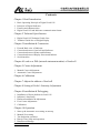
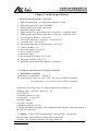
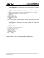
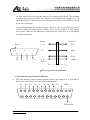
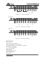
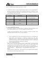
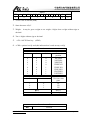
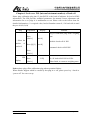
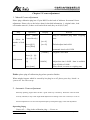
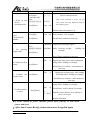
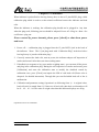
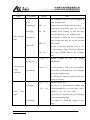
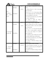
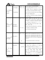
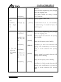
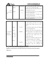
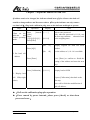
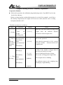
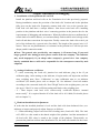
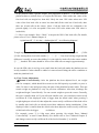
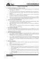
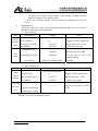
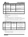
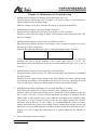
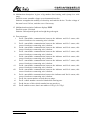
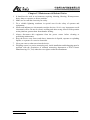
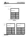
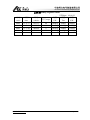
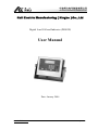
Keli Electric Manufacturing ( Ningbo ) Co., Ltd
Digital Load Cell and Indicator (D2002E)
User Manual
Date: January 2006
www.kelichina.com
Page 1 of 38
Contents
Chapter 1 Brief Introduction
1.
2.
3.
4.
Basic Operating Principle of Digital Load Cell
Principle of Digital Indicator
Features and characteristics
Digital Load Cell and Indicator communication format
Chapter 2 Technical Specification
1. Digital Load Cell Technical Guide Line
2. Technical Guide line of Weight Display
Chapter 3 Installation & Connection
1.
2.
3.
4.
5.
Front & Back view of Indicator
Connection between Load cell and Indicator
Connection between Printer and Indicator
Connection between Display Screen and Indictor
Serial interface
Chapter 4 Look over INS (internal statement number) of load cell
Chapter 5 Corner Adjustment
1. Manual Corner Adjustment
2. Automatic Corner Adjustment
Chapter 6 Calibration
Chapter 7 Adjust the address of load cell
Chapter 8 Setting of Scale’s Linearity Adjustment
Chapter 9 Installation & Debugging
1.
2.
3.
4.
5.
Installation of Scale platform & Load Cell
Indicator’s data Setup
Platform Installation & Adjustment
Four Corner Adjustment
Calibration
Chapter 10 Operation
1.
2.
3.
4.
5.
Start-up & Automatic-zero setting at start-up
Manual Zero setting
Tare deduction operation
Date & Time Setup and operation
Data Record Storage
www.kelichina.com
Page 2 of 38
6. Weight Data Delete
7. Daily Record Print
8. Caution
Chapter 11 Malfunction & Troubleshooting
Chapter 12 Maintenance & Related Notice
www.kelichina.com
Page 3 of 38
Chapter 1 Brief Introduction
1. Basic Operating Principle of Digital Load Cell
Digital Load cell system is a brand new electronic weighing appliance developed from the
traditional strain gauge sensor by using modern micro-electronics technology and
micro-computer integration.
It includes two parts, analogue load cell (strain gauge) and digital converter module.
Converter module is a high-integrated electronic circuit and adopts SMT on the surface. It
mainly includes amplifier, A/D converter, microprocessor ( CPU), memorizer ( EEPROM
calibration memory), interface circuit (RS485 ) and digital temperature load cell.
2. Principle of Digital Indicator
Indicator communicates with digital load cell through the RS485 Interface, and
independent connection is up to 32 load cells. Standard functions are available:
manual/automatic Corner adjustment, addressing and reading data from the individual load
cell automatically, adjusting load cell serial number automatically. It is available for data
processing such display, calibration, send, store, print and so on.
3. Features and Characteristics
A. High Precision, High Reliability
High-integrated electronic circuit and digital solution to error compensation, managing
software is used for the integrated compensation of linearity, zero, rated output,
temperature floating, creep error. It greatly avoids the error caused by using analog
compensation and human negative factors. So it enhances the precision and reliability
greatly.
B. Consistency & Interchangeability
Generally the consistency error of the analog load cell is ≤0.1%. the digital one is
≤0.02% and even more precise. The characteristics and parameter can keep the same in
mass production. Both make it works interchangeably. To replace one digital load cell
in the scale of III grade won’t affect its measuring performance.
C. Good long term stability, great anti-interference ability
It adopts integrated A/D converter, digital signal transmission, and digital filter
technology, increase the signal transmission ability. Signal can be transmitted 1200
meters away. It greatly enhances the anti-interference ability. The analog value
transmitting distance inside the load cell is supper short, meanwhile the elastomer itself
is a good shield cover; these two characteristics make it with high anti-interference
ability. Therefore it improves the load cell long term stability greatly.
D. Self-distinguish and Malfunction diagnosing easily
The digital load cell has the functions of automatic data collecting, pre-processing,
memorizing and storing, and has the exclusive mark. After multi load cells compose
one scale, it can inspect the status of each load cell individually, so the malfunction
www.kelichina.com
Page 4 of 38
diagnosing is easy.
E. High flexibility
All communication via standard communication interface RS485. It is connected to PC
directly or other standard industrial mastering bus. It is easy to use and build the scale.
F. High security, to avoid cheat function
It can prevent remote controller cheating. Be alarming in case of cheating.
4. Digital load cell and indicator communication mode
Communication: 9600 Baud rate, serial interface RS485
Data format instruction: binary code,
www.kelichina.com
Page 5 of 38
Chapter 2 Technical Specification
1. Technical specification of load cell
1. Data Conversion Rate: 10~200 measurements per second
2. Data transmission rate: 9600~38400BPS
3. Digital module A/D count: 10M counts
4. Resolution: 60000 counts
5. Digital module Zero point Temperature Coefficient: <±0.002%F.S/10℃
6. Digital module Sensitivity Temperature Coefficient: <±0.002%F.S/10℃
7. Load cell creep(30min): < ±0.02% F.S.
8. Load cell Temperature Coefficient: <±0.01%F.S/10℃
9. Combined error: <±0.02% F.S
10. Operating temperature of digital module: -40℃-80℃
11. Load cell number: 1-16
12. Zero point output: <±0.1% F.S
13. Safe overload: 150%F.S.
14. Protection: IP68
15. Recommended excitation: 9-12V ( DC)
16. Maximum excitation: 25V ( DC)
17. Maximum signal transmission distance: 1200 meter
2. Technical specification of display terminals
1. performance coefficient
Calibration zero adjustment: ±100%F.S
Zero setting range: power on: ±4% ±10% ±20% ±40% ±100%F.S (optional)
zero setting key: ±1% ±2% ±4% ±10% ±20%F.S (optional)
Automatic zero tracing range: 0.1-9.9d, optional, factory setting 1.0d
Weighing range: -100%F.S-+100% F.S. + 9d
Unit: T, KG, G
Overloading alarm: F.S.+9d
Non-linearity: <0.01% F.S
Plus drift: <6ppm/℃
Zero drift: <10 ppm
Calibration: manual set by key
Linearity adjustment, automatic Corner adjustment and automatic adjust the number of
the load cell on the spot,
2. Display : 6 digits VFD weighing display ( 0.8inch high ), 6 tactile keys
Display range: -9999-999999 excluding the decimal point
Division: 1-99, 99 classes optional, two ranges can be set
www.kelichina.com
Page 6 of 38
Decimal point: three digits decimal point optional
3. communication port: All photoelectricity isolation, direct connection to computer
and display screen
Display screen communication: RS232 & 20Ma electric current loop
selectable. In case of individual connection, address number is able to be changed.
4. Print interface: standard 25 pin parallel interface
5. Keyboard
Number keyboard: 0-9
Function keyboard: 20 key
Material: tactile keyboard
6. Clock
Show in below format: yy/mm/dd, hh/min/sec, automatic adjustment for leap year &
leap month. Automatic Data saving and
precision: ±5s/24h
7. Data storage: 256 printing records; 256 groups. Saving the data >50000h when
power off
8. Requirements
Power supply: AC 200-240V, 49Hz-51Hz
Operation temperature: -10-60
Storage temperature: -25-55
Humidity: ≤90%RH
Warm-up time: 15 min
Fuse: 500mA
Caution: The AC power to this indicator must be earthed reliably
www.kelichina.com
Page 7 of 38
Chapter 3 Installation & Connection
1. Front & Back view of Indicator
Unit:kg
AUTO DATE TIME CONST TARE ZERO
1
2
3
CARGO
VEHICLE
4
5
Auto
Corner-rectify
Manua
FORM PRINT
8
9
Linearity
Correction Preset Tare
0
F1
Corner-Rectify
CHECK
DATE
6
Supplementary
MEMORY PRINT
Print
7
CALIBRATION
Amend Code
Deduct Tare
ENTER
TIME
WEIGH
Memory Tare
ZERO
ON/OFF
(Chart 2-1) Front view of Indicator
(Name plate)
Fuse
Power
(9 pins)
Load cell input
(15 pins)
(25 pins)
RS232
Print output
Calibration socket and display output
(Chart 2-2) Back View
2. Connection between Load cell and indicator
Load cell adopts 9 pins RS232 Terminal. Please refer to chart 2-3 for detailed
www.kelichina.com
Page 8 of 38
information
To make sure the load cell and the indicator are connected effectively. The shielding
conductor should be put to earth. The conductor is not allowed to be plugged in or out
when the indicator is power on to avoid damage to the load cell and indicator caused
by the static electricity.
Load cell and indicator are sensitive to static electricity. So it is not allowed to process
electric welding and other electric related activity on the platform. In the thunder
storm, please make sure the inductor is connected to the earth safely to avoid damage
caused by the thunder.
Display
Shield
⑤
⑨
-E
④
③
⑧
②
⑦
B
Load cell
Red
⑨-E
Black
⑦A
Green
①
⑥+E
⑥
A
+E
⑧B
White
Shield
(Chart 2-3)Load cell connection
3. Connection between printer and indicator
a) The print interface adopts standard parallel output. The terminal is 25 pins RS232.
Please refer to the chart 2-4 for the detailed information.
ST
1
14
DO D1
2
3
15
D2
4
16
17
D3
5
D4
6
18
19
D5
D6
D7
8
9
10
7
20
21
22
23
BUSY
11
12
24
13
25
Signal earth
www.kelichina.com
Page 9 of 38
(Chart 2-4)Printer interface signal
b) Notice of Print
i.
Please set up function before operation.
ii.
Make sure the indicator and printer have been connected with matched wire in a
right way. Otherwise it will damage the indicator and printer terminals or
equipment.
iii.
Before printing, firstly connect the printer and indicator in right way, secondly
power on the indicator then printer. After using, please power off the printer first,
then indicator, at last put off the wire.
iv.
Various printers have different function, so choose one that match the indicator.
Please use the one we recommended which is available under DOS system such as
Canton BJC255SP, Panasonic KX-P1121 and so on.
v.
Signal ground of the printer is not allowed to connect power ground. Otherwise
damage occurs.
4. Connection between Display Screen and Indictor
Make sure the indicator and display terminal have been connected with matched wire in a
right way. Otherwise it will damage the indicator and display terminals, even equipments.
1. The display terminal adopts 25 pins RS232 port (share the same port with PC serial
interface and calibration). Please refer to the chart 2-5 for the detailed information.
PC(1,2)
TXD
GND
1
Control 1
Control 2
Control 3
Control 4 ?
GND
2
3
9
10
OUT+
OUT-
4
11
5
12
6
13
7
14
8
15
TXD
Display terminal ( 9,10: electric current loop mode; 3,11: RS232 mode )
Chart 2-5
2. Display signal: RS232 mode or 20mA electric ring loop mode, binary system inline
output, baudrate 600 baud. 11 digits per group,
3. When display signal output, the indicator will show the weighing data which is
synchronous to VFD. And the indicator light turns on automatically to show that they
are connected in a right way. One group data contains 3 frames of data. Please refer to
the chart for the detailed information.
First frame:
www.kelichina.com
Page 10 of 38
1
0
Bit
0
X
5
6
7
8
d4 d5
d6 d7
Y
G16
(Chart 2-6.1)First frame oscillogram
Second frame:
1
0
Bit
0
5
6
7
8
d4 d5
d6 d7
G8 ——————
G15
9
10
Stop bit
3
4
d2 d3
10
G17
Indicate bit
Start bit
1
2
d0 d1
9
Stop bit
3
4
d2 d3
Indicate bit
Start bit
1
2
d0 d1
(Chart 2-6.2)Second frame oscillogram
Third frame:
1
0
Bit
0
——
5
6
7
8
d4 d5
d6 d7
G7
9
10
Stop bit
G0
3
4
d2 d3
Indicate bit
Start bit
1
2
d0 d1
(Chart 2-6.3)Third frame oscillogram
Data of first frame
Indicate bit is 0
X: D0, D1, D2 are decimal point
Y: D3 is weight sign (1 is minus, 0 is plus)
D4 is net/gross weight (1 is net weight, 0 is gross weight)
D5 is unit (1 is ton, 0 is kg)
G 17, G 16 are weighing data
Data of second frame
Indicate bit is 0
G15-G8: binary system data
Data of third frame
Indicate bit is 1
www.kelichina.com
Page 11 of 38
G7-G0: binary system data
G0-G17: 18 digits binary weighing sign from low to high
4. The indicator is able to connect with the matched display screen by standard RS232.
But the reconnection is required. To the 5 pins plug, connect feet 2 with feet 3, to the
15 pin plug, connect feet 9 with feet 11, and connect feet 10 with feet 12. Please refer
to the chart below after reconnection.
5 pins plug
specification
15 pins indicator terminal
Feet 4、5 connected with feet
12 by short circuit
TXD
11
GND
3.
1
2
3
4
5
Chart 2-1 RS 323 communication mode
5. Serial communication interface
Serial interface should be connected with pc in a right way. Otherwise damage occurs
to the indicator terminal or pc’s even worse damages the indicator and pc.
Computer skill and programmer ability are required by computer operation. Only
qualified personnel are allowed to service this equipment.
i.
Load cell D2002E type realize data transmission between pc and indicator by
serial interface. The transmission is continuous, baudrate 600, 1200, 2400,
9600bps are optional. 15 pins plug is used to connect serial interface and display
terminal. Please refer to chart 2-5 for detailed information on Feet 1, 2 (RS232). It
is better to put the shield into earth at the PC terminal.
ii.
Three communication modes
Mode 1: data is ASCII code, each byte includes 10 digits. Digit 1 is the start bit, digit
10 is the stop bit, and the middle 8 digits are data bit. Each rule digit includes 8 bits
including decimal. Data transmit from low to high, each data rule is separated by “ =”.
The display shows the weighing sign. Take 188.5 for example, continuous transmission
5.88100=5.88100=……. When the digit is –1885, transmission .58810=.58810=……
Mode 2:
Each byte includes 10 digits. Bit 1 is the start bit, bit 10 is the stop bit, and the middle 8
bits are data bit. Each rule digit includes 18 bits.
www.kelichina.com
Page 12 of 38
STX
1
A
B
2
Mode 2
X X X X X X X X X X X X CR
3
4
5
C
CKS
6
1. <STX> ASCII start bit (02H).
2. State character A,B,C
3. Weight: it may be gross weight or net weight. 6 digits show weight without sign or
decimal.
4. Tare: 6 digits without sign or decimal
5. <CR> ASCII Enter key (ODH)
6. <CKS> optional verify and (this indicator don’t send out any verify)
0
State character A
Bits 0 , 1 , 2
1
2
0
1
0
1
0
1
0
1
0
0
1
1
0
0
1
1
0
0
0
0
1
1
1
1
Decimal
position
XXXX00
XXXXX0
XXXXXX
XXXXX.X
XXXX.XX
XXX.XXX
XX.XXXX
X.XXXXX
Bits 3 , 4
3
4
1
0
1
0
1
1
Bit 5
Bit 6
Bits
www.kelichina.com
Division value
gene
X1
X2
X5
Keep 1
keep 0
State character B
function
Page 13 of 38
Bit 0
Bit 1
Bit 2
Bit 3
Bit 4
Bit 5
Bit 6
Gross weight = 0 , net weight = 1
sign :plus= 0 , minus = 1
overload ( or less than 0) = 1
motion = 1
unit : kg = 1
keep 1
When indicate power on it shows 1
Bit 0
Bit 1
Bit 2
Bit 3
Bit 4
Bit 5
Bit 6
State character C
keep 0
keep 0
Keep 0
Print command = 1
Expanded presentation (X10) = 1
keep 1
keep 0
Mode 3
Each byte includes 10 digits. Bit 1 is the start bit, bit 10 is the stop bit, and the middle 8
bits are data bit and parity bit.
Header 1
ST: stability
US: instability
OL: overload
Header 2
GS: gross weight
NT: net weight
TR: tare weight
www.kelichina.com
Page 14 of 38
Chapter 4 Look over INS (internal statement number) of load cell
Please plug calibration plug into 15 pins RS232 at the back of indicator for load cell INS
information. The ISN provides technical parameters for manual Corner adjustment and
information for us to judge it is malfunction or not. Please refer to the below chart for
detailed information.( * is original value, load cell number starts 01, if 4 load cells in total
they are 01,02,03,04)
Step
Operation
Display
Remark
Plug in calibration plug under weighing
Press
1. Select the
number
of
load cell
[check ]
state
[no-01]
Default: check cell 01 ISN
Press [0][2]
[no-02]
command: check cell 02 ISN
Press
[check ]
2.
ISN
display
Press
[check ]
[ 2350]
No. 02 load cell 02 ISN is 02350
When finish, it returns to weighing state.
Notice please plug off the calibration plug when operation finishes
When mistake happen which be caused by hot plug in or off, please press key “check“or
“power off” for a new set up
www.kelichina.com
Page 15 of 38
Chapter 5 Corner adjustment
1. Manual Corner adjustment
Please plug calibration plug into 15 pins RS232 at the back of indicator for manual Corner
adjustment. Please refer to the below chart for detailed information. (* original value, load
cell number starts 01, if there are 4 load cells in total, they are 01,02,03,04 )
Step
Operation
Press
1. Select the
number of load
cell
Display
[Manua
Remark
Plug in calibration plug under weighing
Corner-Rectify]
state
[no- 01]
Press [0][2]
[no- 02]
Default adjust load cell 01
Press [Enter]
command: check cell 02 ISN
[1.00000]
Original Corner data
Press [1]、[0]、
2Adjustment
[0]、[4]、[5]、
[0]
[1.00450]
Adjust data into 1.00450(data is available
from 0.5000 to 2.0000)
press [enter]
When finish, it returns to weighing state
Notice please plug off calibration plug when operation finishes
When mistake happen which be caused by hot plug in or off, please press key “check“ or
“power off” for a new set up
2. Automatic Corner adjustment
Generally speaking, digital load cell has a good sensitivity consistency. When the scale has been
correctly installed, it only needs slight hand adjustment according to the user’s manual, or even do
not need adjustment. If it can not be adjusted equal by hand please apply to the auto adjustment.
Operating Steps:
Power off——Plug in the calibration plug——Power on
www.kelichina.com
Page 16 of 38
Operation
Steps
Press[Auto
Corner-Rectify]
1.Power on and Enter
[1][1][1][1][1][1]
choose
operating mode ,
Press[Enter]
Display
Note
[-------]
Note to enter password
[111111]
[Ant 04]
Only if the password is 111111 can you
carry on the next step, otherwise return to
the weighing states.
Default load cells number is 4;
2.Set
Corner-Rectify
number
3. Set pressing
weight value
Press[0][6]
[Ant 06] Enter number, 6 for example
Press[Enter]
Press
[0][0][5][0][0][0]
Press[Enter] continue to next step
[ 000000]
Display the pressing weight 0
[005000]
Enter Pressing weight ,
example
5000kg for
Press[Enter]
Press [Enter] continue to next step
[No
1]
4. Confirm the first
corner
Press[Enter]
Display the first corner, after loading and
being stable. 5000kg for example
Press[Enter] to confirm,and continue to
next step
[No
2]
5. Confirm the Press[Enter]
second corner
Display the second corner, after loading
and being stable. 5000kg for example
Press[Enter] to confirm,and continue to
next step
N is total corner number, after loading and
being stable. 5000kg for example
[No
7. Confirm number
n corner
Press[Enter]
n]
[ …… ]
[ End ]
Press[Enter], wait for about 30 seconds,
End the Corner-Rectify. Press [Enter] or
power off to quit.
Repeat calibration
▲!Error caused by power intermit, please press [check] or shut down
power and reset.
!After Auto Corner-Rectify, demarcation must be applied again
www.kelichina.com
Page 17 of 38
Chapter 6: Calibration
When indicator is packed before leaving factory, there is also a 15 pins RS232 plug, called
calibration plug which is used to set the related coefficient between the indicator and load
cells.
When the indicator is working, the calibration plug should not be plugged in. Any time
when the plug used, following process should be adopted. Power off-Plug in-Start-Set
coefficient-plug out
Errors caused by power intermit, please press [check] or shut down power
and reset.
1. Power off——calibration plug is plugged into the 15 pins RS232 jack in the back of
the indicator.(Note:The 15 pin plug stuck with “Calibration Plug” in the box before
leaving factory is just the calibration plug).
2. Correctly connect the load cells, turn on power, the indicator adopts self inspection of
strokes and sound. After then, turn into working states.
3. If deadlock (no response to key press under weighing state),you can turn off the power
and plug in the calibration plug. During the self inspection of strokes and sound, press
[Calibration] and enter the calibration state to modify the deadlock caused by
calibration error; press [Check] can inquire the ISN of each load cell (Please refer to
chapter 4 for detailed instruction). Through this you can find which load cell or line is
malfunction.
4. Calibration and parameter setting. Operation is as following form: (*:is original value,
load cell serial is started from 01, if there are 4 load cells, then their serial number will
be 01、02、03、04. The units of weight value that this indicator displays are all kg.
Operation Process of Calibration:
www.kelichina.com
Page 18 of 38
Steps
Operation
Display
Note
The Calibration plug has been plugged in
Press
[Calibration]
under weighing state.
[d1
**]
Means setting the first part division value;
Set the first part division value to 05, 01~99
Press[0][5]
1.Set
division
Value
[d1 05]
available. Press [Check] to skip this step,
press [Weight] back to the weighing state
Press[Enter]
Press [Enter] to finish the first part division
value setting and enter the second division
Press[1][0]
[d2
**]
value setting;
Set the second part division value to 10,
01~99 available. Press [Check] to skip this
[d2 10]
step, press [Weight] back to the weighing
state
[Auto *.*]
tracing
[Auto 2.0]
Press[Enter]
coefficient
original
set
auto
zero
tracing
coefficient
Press[2].[0]
2. Set auto zero
Display
Set zero tracing to 2.0d, 0.1d~9.9d available.
Press [Check] to skip this step, press [Weight]
back to the weighing state
Press [Enter] to finish the setting of auto zero
tracing coefficient.
[CLr **]
Press[0][1]
Set Zero to 01, 00/01/02/03/04/ available. Start
[CLr 01]
3.Set
Zero
Display original Zero
Zero are separately 4%、10%、20%、40%、100%,
manual 1%、2%、4%、10%、20%.
range
Press [Check] to skip this step, press [Weight]
back to the weighing state
Press[Enter]
Press [Enter] to finish the setting of Zero
range.
www.kelichina.com
Page 19 of 38
[Prt **]
Press[0][1]
format
[Prt 01]
Set printing format to 1, that is non printing
single unite format
4.Set
ponderation
form
Display original set ponderation form printing
printing
Choices:00、01、02、03 series, they are filling
Press[Enter]
style, non filling single unite, non filling double
unite, non filling three or four unite.
format
Press [Check] to skip this step, press [Weight]
back to the weighing state
Press [Enter] to finish the setting of
ponderation form printing format.
[Ps **]
Press[0][2]
Display original set paper feeding mode.
Set paper feeding mode to 02, that is continuous
[Ps 02]
feeding mode and able to feed and withdraw
paper automatically.
Choices:00、01、02;00 is paper form feeding
mode. That is when printing a ponderation
5.Set the paper
feeding mode
form, a new paper adopts; 01 is continuous
Press[Enter]
paper feeding mode;
02 is continuous paper feeding mode and able
to feed and withdraw paper automatically.
Press [Check] to skip this step, press [Weight]
back to the weighing state
Press [Enter] to finish the setting of paper
feeding mode.
Press[0][4]
[Ant-**]
Display original set load cell number
[Ant-04]
Set load cell number to 4(range 1-10),Press
6.Set the load
[Check] to skip this step, press [Weight] back
cell number
to the weighing state
Press[Enter]
Press [Enter] to finish the setting of load cell
numbers.
www.kelichina.com
Page 20 of 38
Press[0][1]
[Pont
**]
Display original set decimal number
[Pont
01]
Set the decimal number to one. 00、01、02、03
is available. They are separately no decimal,
7.Set displayed
one decimal, two decimal and three decimal.
decimal
Press[Enter]
number
Press [Check] to skip this step, press [Weight]
back to the weighing state
Press [Enter] to finish the setting of displayed
decimal number.
[bt
**]
Display original set baud rate and verify
mode. Perch is verify mode: 0 stands for no
verification, 1 stands for odd and 2 stands for
even; Lowness is baud rate: 0、1、2、3、4
8.Set
PC
separately stands for baud rate 9600、4800、
communication Press[0][1]
2400、1200、600.
baud rate
Stands for baud rate 4800 and no verification;
Press[Enter]
[bt 01]
Press [Enter] to finish the setting.
Press [Check] to skip this step.
[pt
**]
9.
Set Press [0][1]
communication
agreement
[pt
Display original set communication mode. 00
stands for the communication mode one, 01
stands for the communication mode three, 02
stands for the communication mode two; For
details please refer to the user’s manual page
9 and 10;
Set communication mode to mode three
01]
[Lb **]
Press[3][2]
Display original set strain wave coefficient
Set strain wave coefficient to 32, the first
[Lb 32]
number stands for strain wave range. 0、1、2、
10 Set strain
3、4、5 available,separately stands for weaving
wave
range 0kg、100kg、200kg、300kg、400kg、
coefficient
500kg;the second number stands for strain
wave strength. 0、1、2、3、4、5 available. The
bigger the number is, the stronger the strain
www.kelichina.com
Page 21 of 38
weave is.
Press [Check] to skip this step, press [Weight]
back to the weighing state
Press [Enter] finishes the setting of strain
Press[Enter]
wave coefficient.
[SC **]
Display original set units code;
[SC 01]
Set units code to 01, 00,01,02 is available,
11.Set
ponderation
form
Press [0]、[1]
00 stands for kg、01 stands for T(ton)、02
display
stands for gram.
units
[FULL1]
Press[Enter]
Press [Check] to skip this step, press [Weight]
back to the weighing state
[000800]
Press[0]、[0]、
Display original first subsection full capacity
value to 800Kg
[2]、[0]、[0]、
[0]
Press[Enter]
12. Set scale
subsection
full capacity
value
[002000]
[FULL2]
Press[Enter] to finish first subsection full
capacity value modification; And enter the
setting of second subsection full capacity
Press[Enter]
Press[0]、[1]、
Change the full capacity value to 2000Kg
value;
[005000]
[0]、[0]、[0]、
Display original set second subsection full
capacity value to 5000Kg
[0]
Change the full capacity value to 10000Kg
Press[Enter]
[010000]
Press[Enter] to finish second subsection full
capacity value modification; And enter the
setting of second subsection full capacity
value;
www.kelichina.com
Page 22 of 38
[noLoAd]
[Enter]
Check scale dead load span. Press [Enter]
after the scale is unloaded and stable
Displays the ISN value under unload state,
13.
Check
scale dead load
[000000]
[Enter]
Press [Check] to skip this step, press [Weight]
[------]
span
which should close to zero.
back to the weighing state
Press [Enter] and wait for 1~2 seconds,enter
the next step automatically.
Press [Check] to skip this step, press [Weight]
back to the weighing state
[AlloAd]
Load the calibrated weight value, the closer to
the full capacity the better, for example
10000Kg. Press [Enter] after the scale is
stable.
[Enter]
[******]
Press [Check] to skip this step, press [Weight]
back to the weighing state
[Enter]
14 Load the
Display the ISN value of the digital load cell
[000000]
after being loaded. As the digital load cells
calibrated
Press[0] 、
are calibrated before releasing from factory,
weight value
[1] 、 [0] 、
normally the value should close to the
[0] 、 [0] 、
loading weight value.
[0]
Display the set calibration weight value state.
Set calibrated weight value to 10000Kg
[Enter]
Waiting for 1-2 seconds, quite calibration
[010000]
state and back to the weighing state
automatically. Then the calibration has
[------]
finished.
▲ ! Pull out the calibration plug after operation.
▲!Error caused by power intermit, please press [check] or shut down power
and reset.。
www.kelichina.com
Page 23 of 38
Chapter 7: Adjust the address of Load Cell
If address needs to be changed, the indicator should turn off first. Connect the load cell
needed to change address and disconnect others.(Note:the indicator can only connect
one load cell.),Plug in the calibration plug, turn on the indicator and begin to operate.
Steps
Operation
Display
Press
[Amend [-------]
1Turn on the
Code]
indicator
and
Enter
choose operating
[1][1][1][1][1][1], [111111]
mode
Press[Enter]
[No
**]
address
Ask to enter password
Only when the password is 111111, can
the next step continue, otherwise back
to the weighing state;
Display original set load cell serial
number.
Press [0][2]
[No
2 Set load cell
Note
02]
Press [Enter]
Set the address to 2, 01~16 is available
Press [Enter] to confirm to finish the
setting of the address and enter the next
step.
Press [Calibration]
[******]
Display load cell ISN
3.Display load
cell ISN(weight
If press [Calibration], then back to the
value)
first step
Power off to finish the modification of
load cell address.
▲ !Pull out the calibration plug after operation.
▲ !Error caused by power intermit, please press [check] or shut down
power and reset.。
www.kelichina.com
Page 24 of 38
Chapter 8 Setting of Scale’s Linearity Adjustment
1. Operation Method:
▲!Before this operation, the calibration plug should plug in the 15 pin RS232 jack in the
back of the indicator.
Before revising, load the weight which needs to be revised(For example:a scale fits to
the linearity requirements on weight 0-30T but not on 40T, then the scale’s revising
load point should be 40T)
Detailed operations are as follows:
Steps
Operation
Display
Notes
When the scale has loaded revising point
1、Ready
Load
the
weight
of
[******]
weight
value,
the
indicator
displays
exceeded or lacked weight value;
revising point
2. Turn on
the
indicator
and choose
operating
mode
Press[Linearity
Correction]
Enter
[1][1][1][1][1][1
],
Press[Enter]
[-------]
Ask to enter password
[111111]
Only when the password is 111111, can the
next step continue, otherwise back to the
weighing state;
[S 00]
Default is 00 and do not carry on linearity
revising. If the number is bigger than 00
then carry on linearity revising.
Enter 01 and begin linearity revising;
Ask to enter revising point weight value.
Press[0][1]
Press[Enter]
3、Enter Enter
Revising
[4][0][0][0][0]
[S 01]
[000000]
[040000]
Enter weight value to 40000kg
The indicator return to the weighing state
and display weight 40000kg;
Press[Enter]
[040000]
www.kelichina.com
Page 25 of 38
Chapter 9 Installation & Debugging
1. Installation of Scale platform & Load Cell
Install the platform and load cells on the Foundation level that previously prepared.
During installation, ensure the precision of the load cells’ location and let the platform
fully press on the load cells. Separately connect load cells’ wire to the junction box.
Each load cell shall have a unique address. Note down each load cell’s installing
position in the platform and their wires’ connecting position in the junction box for the
requirements of debugging and maintenance. When the indicator shows a malfunction of
certain load cell with its address, we can immediately find out which wire belongs to this
load cell and thus convenient for inspection. Finally connect the load cells to the 9 pin
jack of the indicator by a general wire (Provided). The length of the general wire is 15
meters. There are no potentiometers or resistance in the junction box. All four pin wire
adopts parallel connection mode.
▲Note: The general wire provided by our company is 15 meters long. If you need
longer general wire during practice please contact with our company. The indicator
may work improperly if you adopt other company’s general wire. Our company
hereby reminded that we will not be responsible for the consequence caused by such
adoption!
2、Setting of indicator coefficient
(1)After connecting the Load cell, junction box and indicator, plug in the 15 pin
calibration plug. After turning on the indicator, it begin stroke self inspection and then
enter weighing state. Press “Calibration” to enter calibration state to set indicator
coefficient (For details please refer to chapter VI). Set indicator’s load cell number
according to the connected load cells. Press”Weigh” back to the weighing state, you can
also press “Check” to enter coefficient setting until back to the weighing state.
( 2 ) Then inspect each load cell’s corner-rectify coefficient K(Press “manual
corner-rectify”. It is required that the K of the load cell is all 1.0000 (For details please
refer to chapter V).
3、Platform Installation & Adjustment
In order that the installed platform is level and the load cells share balanced force, use
indicator to inspect and properly adjust. Steps are as follows:
(1)When unloading, inspect each load cell’s loading state (Load cell’s ISN). The load
cell’s ISN is a value round to the shared weight of the platform. And the summation of
all load cells’ ISN value is round to the weight of the platform. Theoretically we
presume the platform uniform mass distribution. So, the load cells installed in the center
www.kelichina.com
Page 26 of 38
of the platform share a greater weight. This proportion is about 2:1. In order that the
platform shares a uniform force, we require the ISN max. Value minus min. value of the
four load cells on margin less than 400; Likely the max. ISN value minus min. ISN
value of the four load cells in center less than 400.(If the scale has 8 load cells, then
there are 4 load cells in the center). (Note: if all the load cells are confirmed to be
pressed tightly, it is also acceptable if the max. ISN value minus min. ISN value is
inside 800).
(2)Here is an example: Press “Check” to inspect the ISN of the load cells (For details,
please refer to User’s Manual chapter 4)
A platform 60T(3.4×14m),deadweight 10T(As following diagram)
①
②
③
④
⑤
⑥
Trough inspection their ISN value are ① 1290
②2460
③1310
④1240
⑤2520
⑥1180. Among them, load cells number ①、③、④、⑥ has close bearing weight and the
difference is usually no more than 400kg. It is also right for load cells in the center number
②、⑤, but their ISN value should be twice of the load cells on margin (approximately).
In case the ISN value is too big or too small, then the load cells under the platform are not
levelly installed. Gasket should be added or removed until fitting the above condition to
make the platform level.
4、Four Corner Adjustment
①Manual Corner-Rectify: After the platform has been adjusted level, use weight
(Car for example), which should be as nearer to the full capacity as possible, to press it.
After 5-6 times’ come and go pressing; the parts of the platform become stable. Then put
certain weight on platform to carry on previous calibration. After that, discharge the
weight and begin Corner-Rectify. Use one certain weight to press the corner. Generally,
the error is smaller than 1d. If you still need smaller error, you can adjust corner-rectify
coefficient K If the displayed value is bigger than the actual value when pressing a
weight right upon a load cell, then adjust the corner-rectify coefficient of this load cell to
be smaller (the load cells are already noted their addresses during installation); If the
displayed value is smaller than the actual value then adjust the corner-rectify coefficient
of this load cell to be bigger.
As follows:
For example, corner ② is 10kg more when pressing 10t weight. Press “Manual
Corner-Rectify” to enter Corner-Rectify (For details refer to User’s Manual Chapter 5)
and change corner-rectify coefficient K of the load cell number ② to 0.9850
www.kelichina.com
Page 27 of 38
Estimated Formula is as follows:
Difference
+10
Corner-Rectify Coefficient K=1- ———————— =1- ——————
Pressing Weight *75%
10000*75%
You can also directly try several data to avoid estimation.
Note: If the weight is 10kg less, then the difference in the formula will be –10.
②Auto Corner-Rectify: For details refer to Chapter 5.
5、Calibration
Enter the calibration function under unload and stable state. Press “Enter” in “noload” to
set zero point. After that the indicator displays “Alload”. Then load calibration weight.
The closer to the full capacity the better, for example 10000Kg. Press “Enter” after the
platform is stable, there will be a value displayed in the indicator, which shows load cells’
ISN. In normal conditions, the value should be near to the calibration weight, for example
around 10000. Press “Enter” again and the indicator display “000000”. Then enter loaded
weigh, for example 10000. Wait for several seconds and quit calibration state automatically.
Till now, the calibration has finished and can begin inspection and usage.
www.kelichina.com
Page 28 of 38
Chapter 10: Operation
1.
Start-up & Automatic-zero setting at start-up
i.
Power on. The indicator will be under measuring status after self examination
from ‘000000’ to ‘999999’.
After start-up, the device will compensate for small changes in zero if the value is
not zero but still in the zero range (±4% ±10% ±20% ±40% ±100%F.S are
optional)
ii.
‘Deduct Tare’ is available while the calibration plug is on the 15 pins socket
(normally it is taken off to avoid wrong operating).
iii.
ON/OFF is available to shut down the indicator while measuring, press another
time can start the device again, and then examine itself. Make sure that the power
is off while installing, thundering or being set idle for a long time.
2. Manual zero setting (semiautomatic)
i.
Press “ZERO” to set the device, the “ZERO” signal will be lighted on then. If the
value displayed is not in the zero range, it displays [Err42].
ii.
Only if the value is in the zero range can the device be reset to zero. Otherwise
“ZERO” is invalid.
iii.
ZERO setting can be operated while the stable signal is lighting, it is invalid
while the stable signal is glittering.
3. Tare deduction operation
The signal will be lighted on with N.W displayed after pressing “Deduct Tare”; press
the key once more, G..W will be displayed with the signal go out. If the value is
smaller than zero, the key is invalid.
4. Date & Time Setup and operation
i.
Press “DATE” under measuring status, the current date will be displayed with the
signal lighted on. Press “CHECK” to confirm if the setup is correct, if not press
“ENTER” then rectify the numbers, press “ENTER” to confirm.
ii.
Press “TIME” under measuring status, the current time will be displayed with the
signal lighted on and carry on at the same time. Press “CHECK” to confirm if the
value is correct, if not press “ENTER” then rectify the numbers, press “ENTER”
to confirm.
5. Data Record Storage
i.
As prescribed vehicle number should be 5 digits, and cargo number should be 2
digits.
ii.
Up to 256 printing data groups can be stored.
iii.
There are three ways to deal with data:
¾ Measure gross weight ahead of net weight or on the contrary. It means in
order to differentiate gross weight and tare automatically there are two steps
to be executed.
¾ Measure gross weight only with tare known and input. So one step is enough.
¾ Measure the cargo only. Totally one step is needed to have the record. Vehicle
number is 00000.
In order to differentiate above three ways to measure automatically, we have rules
as bellow:
www.kelichina.com
Page 29 of 38
iv.
Step
vehicle
number
setup
9 Vehicle number must be a value between 00001 and 99999. That is to
say 0000 is not a legal vehicle number. If the number is 00000, the third
method is adopted to weigh the goods.
9 If the tare is known already, one time testing is enough to have the full
record.
Detailed steps:
STEP one: input tare (if the value has been existing already, there is no need to
change it so this step can be neglected)
¾ Tare is known
Description
Press [Vehicle]
Press[1][2][3][4][5]
Press[Enter]
Display
Under measuring status
[o
]
[o12345]
[o12345]
Notes
Display a blank Vehicle NO.
Input Vehicle No. 12345
Confirm to next step
Press[Preset Tare]
Tare
setup
press[0][0][0][5][0][0]
[o00000]
[o00500]
press[Enter]
Back to measuring status
The current tare is 0Kg
Set the tare of NO. 12345
vehicle 500Kg
confirm
¾ Tare is unknown
Step
Input
vehicle
number
Set present
Description
Press[Vehicle]
Press[1][2][3][4][5]
Press[Enter]
Display
Under measuring status
[o
]
[o12345]
[o12345]
Press[Memory Tare]
weight as
[------------]
Notes
Display a blank Vehicle NO.
Input Vehicle No. 12345
Confirm to next step
Data processing, store the
value to be the tare of vehicle
12345
Back to measuring
status after seconds
¾ It displays [ERR 43] while the vehicle NO. is set 00000 at the first step. Press
“ENTER” to be back to measuring status.
tare
www.kelichina.com
Page 30 of 38
STEP two:
Step
1
2
3
¾
6.
7.
¾
¾
8.
Step
Description
Press [Memory Print]
Input vehicle NO.
press[Enter]
Input [3][5]
press[Enter]
Under measuring
status
[o
]
[o12345]
[hn ]
[hn 35]
Notes
Input Vehicle No.:12345
[Err 44] is displayed if the vehicle
NO. does not exist, press [Enter]
back to measuring status
Cargo NO.:35
Back to measuring status
After accurate operation with G.W and N.W above zero, it is ok to print the
weight bill of each vehicle( see appendix), printing format can be set in
calibration setup
Data can not be recorded with [Err 45] displayed while it is not stable or N.W≤0 or
G.W≤0.
Supplementary Print
Press “Supplementary Print” to print the weight bill again.
Data deleting
Note: all stored data can be deleted after the following steps are operated.
Press F1 under measuring status, [-------] will be displayed. After input password
[111111], press “ENTER” until “SURE” is shown. The device will return to measuring
status automatically 5 minutes later. Keys are invalid with [-------] displayed.
New data will cover the first data record automatically while there are over 256
records.
Daily report form printing
Description
Date
setup
Display
Display
Notes
Under measuring
Press [Form Print]
status
date & time setup
Press [0][9][1][0]
[ 00-00 ]
Print form edited on 10th Sep
Press [Enter]
[ 09-10 ]
Confirm the printing date
Enter[check]
Back to measuring status
print
[ print]
Print daily report form
Back to measuring status
9. Notes
¾ Do not press any key while printing.
¾ The key “Weigh” can be used to re-boot the device when it displays [print] for a long
time when the printer is unavailable.
www.kelichina.com
Page 31 of 38
Chapter 11: Malfunction & Troubleshooting
1.
Malfunction description: No display and no buzz after power on.
Possible Reason: Maybe the fuse is broken, or no power source, or the transformer
inside crashes because of high voltage.
Solution: Change a new fuse, check the electricity, or check the transformer.
2.
Malfunction description: Abnormal display and buzz.
Possible Reason: Maybe the electricity is not stable, or CPU is broken.
Solution: re-boot after the voltage is stable, if the situation is the same maybe the CPU
has to be changed.
3.
Malfunction description: it shows there are different corners.
Possible Reason: Maybe the base of the balance is not so solid, and sensors are not on
the same level after a long time.
Solution: Re-adjust the different corners or adjust the height of the sensor base.
①
②
③
④
⑤
⑥
Adjust the balance according to inner code of sensors (see section 4). Generally
speaking, the sum of all the numbers is the weight. Inner code of ①④③⑥ are
basically the same, the difference can be no more than 400kg, the value of ②⑤ are as
twice as ①④.
4.
Malfunction description: it shows that there is data floating.
Possible Reason: maybe sensors are affected with damp; the function of insulating
becomes weaker.
Solution: Protect sensors from constant water effect. Replace the sensor with the same
specification and address. Find detailed instruction in section 4, checking the inner
code of each sensor can help to find the right one which causes data floating.
5.
Malfunction description: it displays Err 01 while installing or working.
Possible Reason: maybe No. 1 sensor is broken or the connection is too poor.
Solution: check the connection among sensors, junction box and indicator. Search for
No. 1 sensor, if no NO. 1 sensor is found, that means the address is modified. Set the
address back to the original setup via the indicator according to the eligibility mark
(see section 7). If No.1 sensor is found, please test the voltage between the red wire
and black wire. If there is a 9-12V voltage, it is concluded that the sensor is broken;
replace the broken one. If there is no voltage, test the voltage between the red wire and
the black wire on the DB9 plug that is used to connect the indicator and junction box.
If there is a 9-12V voltage, the connecting wire is broken. Otherwise the indicator is
broken.
6.
How to find which sensor is broken.
www.kelichina.com
Page 32 of 38
Turn the indicator off, plug in the address modifying plug, and connect the sensor to
the indicator (they can only be tested one by one). Power on, the code of the sensor
will be displayed after self examination. Press ENTER, the load value will be shown
according which we can indicate whether the sensor is ok or not (find detailed
information in section 7).
7.
How to judge the breakdown of an indicator.
Connect a spare sensor to the indicator, plug the calibration head in, and press
CALIBRATE while self-examining. Set the number of sensors to be ‘1’, if it works
normal after exiting, that is to say the indicator is ok otherwise it is broken.
8.
Malfunction description: Constant displaying of disordered data.
Possible reason: the interfaces of indicator and screen do not match.
Solution: find the connection indication in the manual, and make the connection
according to that.
9.
Malfunction description: it shows ‘…………….’ after self-examining.
Possible reason: wrong connection of the green wire and white wire in junction box.
Solution: cut off the electricity. Check the connection between cables to bus through
an indicator, red-red, black-black, white-white, green-green, make sure that there is no
short circuit.
10. Malfunction description: no display in weighing software after connecting an indicator
to a PC.
Possible reason: the connection between them is incorrect or bound rate does not
match each other.
Solution: find the connection indication between them in the manual; check the
connection and bound rate.
11. Malfunction description: disordered data displayed in weighing software after
connecting an indicator to a PC.
Possible reason: Bound rate does not match each other.
Solution: Set the bound rate in the indicator and weighing software.
12. Malfunction description: A big and stable number is shown in the indicator still after
the tested vehicle moves out.
Possible reason: the limit position is blocked.
Solution: check the limit position, and fix it to the right place.
13. Malfunction description: Err message is shown after booting. The indicator tests each
sensor under address modifying status and all the sensors are proved to work well.
Connect sensors one by one from NO. 1, and the indicator shows err message without
having all of them connected.
Possible reason: the power of this indicator is limited.
Solution: replace it with a more powerful one
www.kelichina.com
Page 33 of 38
14. Malfunction description: It gives a big number after booting, and it jumps in a wide
range.
Possible reason: unstable voltage or environmental interfere
Solution: strengthen the stability of electricity and earth the device. Test the voltage of
the metal cover if it has, earth the cover if necessary.
15. Malfunction description: Indicator displays FFFF
Possible reason: Overload
Solution: Unload partial goods and weigh the goods again
16. Error messages:
i.
Err02: unavailable communication between the indicator and No.2
sensor is broken or its connecting wire is broken.
ii.
Err03: unavailable communication between the indicator and No.3
sensor is broken or connecting wire is broken.
iii.
Err04: unavailable communication between the indicator and No.4
sensor is broken or connecting wire is broken.
iv.
Err05: unavailable communication between the indicator and No.5
sensor is broken or connecting wire is broken.
v.
Err06: unavailable communication between the indicator and No.6
sensor is broken or connecting wire is broken.
vi.
Err07: unavailable communication between the indicator and No.7
sensor is broken or connecting wire is broken.
vii.
Err08: unavailable communication between the indicator and No.8
sensor is broken or connecting wire is broken.
viii.
Err09: unavailable communication between the indicator and No.9
sensor is broken or connecting wire is broken.
ix.
Err10: unavailable communication between the indicator and No.10
sensor is broken or connecting wire is broken.
x.
Err42: the current number exceeds the zero range.
xi.
Err43: vehicle number can not be blank while entering tare.
xii.
Err44: the tare of this vehicle number has not stored yet.
xiii.
Err45: unable to store, data is not stable or N.W≤0, or G.W≤0.
www.kelichina.com
sensor, this
sensor, this
sensor, this
sensor, this
sensor, this
sensor, this
sensor, this
sensor, this
sensor, this
Page 34 of 38
Chapter 12 Maintenance & Related Notice
1.
2.
3.
4.
5.
6.
7.
8.
It should not be used in environments requiring vibrating, librating, Hi-temperature,
dusty, damp or exposure to direct sunshine.
Make sure to earth the electricity for safety.
Fix a reliable lightning conductor in special area for the safety of operator and
equipments.
Sensor and indicator are electrostatic sensitive devices. So it is very important to avoid
electrostatic effect. Do not do electric welding and other strong electric field operation
on the platform; protect them from thunder striking.
Always disconnect this equipment from the power source before cleaning or
performing maintenance.
Keep the device away from wash down, immersion in liquids, exposure to splashing
liquids, or exposure to corrosive chemicals.
Never put water or other mess into the device.
Weighing screen is a precise measuring tool, inside installation and debugging must be
operated with the permission of national measuring department or Keli Electric
Manufacturing CO., Ltd, others have no right to make the amendment.
www.kelichina.com
Page 35 of 38
Appendix:
1.
Weight bill ( full printed):
一联:
first page
过磅单
WEIGHT BILL
序号 SERIAL
0001
日期 DATE
02-08-21
时间 TIME
17:33:09
车号 VEHICLE
012345
货号 CARGO
88
毛重 GROSS
9905kg
皮重 TARE
500kg
净重 NET
9405kg
司磅员/operator:
二联:
Second
page
过磅单
过磅单
WEIGHT BILL
WEIGHT BILL
序号 SERIAL
0001
序号 SERIAL
0001
日期 DATE
02-08-21
日期 DATE
02-08-21
时间 TIME
17:33:09
时间 TIME
17:33:09
车号 VEHICLE
012345
车号 VEHICLE
012345
货号 CARGO
88
货号 CARGO
88
毛重 GROSS
9905kg
毛重 GROSS
9905kg
皮重 TARE
500kg
皮重 TARE
500kg
净重 NET
9405kg
净重 NET
9405kg
www.kelichina.com
Page 36 of 38
司磅员/operator:
司磅员/operator:
三联:third page
过磅单
WEIGHT BILL
过磅单
WEIGHT BILL
过磅单
WEIGHT BILL
序号 SERIAL
0001
序号 SERIAL
0001
序号 SERIAL
0001
日期 DATE
02-08-21
日期 DATE
02-08-21
日期 DATE
02-08-21
时间 TIME
17:33:09
时间 TIME
17:33:09
时间 TIME
17:33:09
车号 VEHICLE 012345
车
号 012345
VEHICLE
车
VEHICLE
货号 CARGO
88
货号 CARGO
88
货号 CARGO
88
毛重 GROSS
9905kg
毛重 GROSS
9905kg
毛重 GROSS
9905kg
皮重 TARE
500kg
皮重 TARE
500kg
皮重 TARE
500kg
净重 NET
9405kg
净重 NET
9405kg
净重 NET
9405kg
司磅员/operator:
2.
司磅员/operator:
号 012345
司磅员/operator:
.weigh bill(form-filling printed)
:
0001
02-08-21
17:33:09
012345
88
9905kg
500kg
9405kg
3.
daily report form(fully printed):
www.kelichina.com
Page 37 of 38
日报表/daily report form
日期/date:02-08-23
序号
serial
时间
time
车号
vehicle
货号 cargo
毛重
G.W
皮重
Tare
净重
N.W
0001
11:31:37
011111
88
3998Kg
500Kg
3498Kg
0002
11:32:11
012345
00
3997Kg
500Kg
3497Kg
0003
11:37:05
099999
77
3997Kg
850Kg
3147Kg
0004
14:26:25
000000
99
3999Kg
0Kg
3999Kg
www.kelichina.com
Page 38 of 38