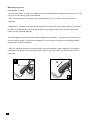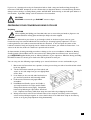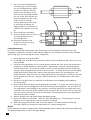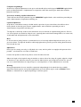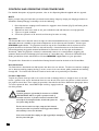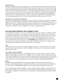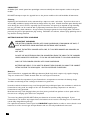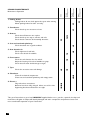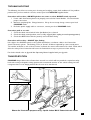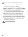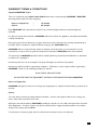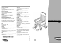
1
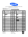
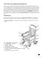
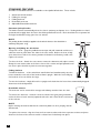
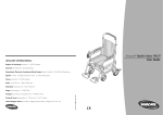
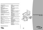
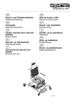
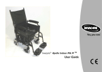
European Headquarter:
Nederland:
Invacare International Sàrl, Route de Cité-Ouest 2,
CH-1196 Gland
Tel: (41) (0)22 354 60 10, Fax: (41) (0)22 354 60 11
[email protected]
Invacare BV, Celsiusstraat 46, NL-6716 BZ Ede
Tel: (31) (0)318 695 757, Fax: (31) (0)318 695 758
[email protected]
[email protected]
Sales Units:
Belgium & Luxemburg:
Norge:
Invacare nv, Autobaan 22, B-8210 Loppem
Tel: (32) (0)50 83 10 10, Fax: (32) (0)50 83 10 11
[email protected]
Invacare AS, Grensesvingen 9, Postboks 6230,
Etterstad, N-0603 Oslo
Tel: (47) (0)22 57 95 00, Fax: (47) (0)22 57 95 01
[email protected]
[email protected]
Danmark:
Österreich:
Invacare AIS, Sdr. Ringvej 39, DK-2605 Brøndby
Tel: (45) (0)36 90 00 00, Fax: (45) (0)36 90 00 01
[email protected]
Mobitec Mobilitätshilfen GmbH, Herzog Odilostrasse 101,
A-5310 Mondsee
Tel.: (43) 6232 5535 0, Fax.: (43) 6232 5535 4
[email protected] , [email protected]
Deutschland & Eastern Europe:
Portugal:
Invacare Aquatec, Alemannenstraße 10, D-88316 Isny
Tel: (49) (0)75 62 7 00 0, Fax: (49) (0) 75 62 7 00 66
[email protected]
Invacare Lda, Rua Senhora de Campanhã 105,
P-4369-001 Porto
Tel: (351) (0)225 1059 46/47, Fax: (351) (0)225 1057 39
[email protected]
Ulrich Alber GmbH, Vor dem Weissen Stein 21, D-72461
Albstadt-Tailfingen
Tel: (49) (0)7432 2006 0, Fax: (49) (0)7432 2006 299
[email protected]
Sverige & Suomi:
Eire:
Dolomite AB, Box 55, V. Götgatan 5, S-33421 Anderstorp
Tel: (46) (0)371 58 84 00, Fax: (46) (0)371 170 90
[email protected]
Invacare Ireland, Unit 5 Seatown Business Campus, Seatown
Rd, Swords, Dublin - Ireland
Tel: (353) 1 8107084, Fax: (353) 1 8107085
[email protected]
InvacareR Apollo Indoor Mk.IV
Invacare AB, Fagerstagatan 9, S-163 91 Spånga
Tel: (46) (0)8 761 70 90, Fax: (46) (0)8 761 81 08
[email protected]
[email protected]
User Guide
Switzerland:
Mobitec Rehab AG, Benkenstrasse 260, CH-4108
Witterswil
Invacare SA, c/Areny s/n, Polígon Industrial de Celrà, E-17460 Tel.: (41) (0) 61 487 70 80, Fax.: (41) (0) 61 487 70 81
Celrà (Girona)
[email protected]
[email protected]
Tel: (34) (0)972 49 32 00, Fax: (34) (0)972 49 32 20
[email protected]
United Kingdom & Eire:
Invacare Ltd, South Road, Bridgend Industrial Estate,
France:
UK-Bridgend CF31 3PY
Invacare Poirier SAS, Route de St Roch, F-37230 Fondettes
Tel: (44) (0)1656 664 321, Fax: (44) (0)1656 667 532
Tel: (33) (0)2 47 62 64 66, Fax: (33) (0)2 47 42 12 24
[email protected]
[email protected]
[email protected]
España:
Invacare Mecc San s.r.l., Via dei Pini 62, I-36016 Thiene (VI)
Tel: (39) 0445 38 00 59, Fax: (39) 0445 38 00 34
[email protected]
WWW.INVACARE.CO.UK
MSS Ltd, MSS House, Taffs Fall Road, Treforest
Industrial Estate,
UK- Cardiff CF37 5TT
Tel: (44) (0)1443 849200 - Fax: (44) (0)1443 843377
[email protected]
Part No: 1416069 - 1206
Italia:
ISO 7176-15:1996 REQUIREMENTS FOR INFORMATION DISCLOSURE
DOCUMENTATION AND LABELLING
MANUFACTURER: Invacare Limited
ADDRESS: South Road. Bridgend Industrial Estate. Bridgend. Mid Glamorgan. CF31 3PY
MODEL DESIGNATION:
APOLLO Mk1V INDOOR POWERCHAIR
MAXIMUM OCCUPANT MASS (WEIGHT):
127Kg
ISO TEST
METHOD
REQUIREMENT
Overall Length with Legrest
ISO 7176
Pt 5
ISO 7176
Pt 5
ISO 7176
Pt 5
ISO 7176
Pt 5
ISO 7176
Pt 5
ISO 7176
Pt 5
C.E.N
ISO 7176
Pt 1
ISO 7176
Pt 1
ISO 7176
Pt 1
ISO 7176
Pt 4
ISO 7176
Pt 2
ISO 7176
Pt 10
ISO 7176
Pt 6
ISO 7176
Pt 3
Overall Width
16in Wide
17in Wide
18in Wide
19in Wide
20inWide
Folded Length
15in Wide
Folded Width
Folded Height
Total Mass (Weight)
Mass (Weight) of the Heaviest
Part
Static Stability Downhill
Static Stability Uphill
Static Stability Sideways
Energy Consumption (Range)
Dynamic Stability Uphill
Obstacle Climbing
Maximum Speed Forward
Minimum Braking Distance From
Maximum Speed
MIN
MAX
ISO TEST
METHOD
870mm 970 mm
ISO 7176
(i)
(ii)
Pt 7
580mm 580mm
605mm 605mm
630mm 630mm
655mm 655mm
680mm 680mm ISO 7176
705mm 705mm Pt 7
620mm 620mm ISO 7176
Pt 7
ISO 7176
400mm 400mm
Pt 7
ISO 7176
750mm 750mm
Pt 7
ISO 7176
Kg
Kg
Pt 7
ISO 7176
Kg
Kg
Pt 7
ISO 7176
23°
25.5°
Pt 7
ISO 7176
14.5°
17°
Pt 7
ISO 7176
21°
21°
Pt 7
ISO 7176
km
km
Pt 7
ISO 7176
6°
Pt 7
G
ISO 7176
mm
mm
Pt 5
ISO 7176
km/h
km/h
Pt 5
mm
mm
REQUIREMENT
MIN
MAX
4°
4°
417mm
442mm
467mm
492mm
517mm
542mm
410mm
435mm
460mm
417mm
442mm
467mm
492mm
517mm
542mm
410mm
435mm
460mm
Seat Plane Angle
Seat Width
15in Wide
16in Wide
17in Wide
18in Wide
19in Wide
20inWide
Seat Depth
16in Deep
17in Deep
18in Deep
Seat Surface Height at Front
Edge
Backrest Angle 10° Folding
Reclining Back
Backrest Height 10° Folding
Reclining Back
Footrest to Seat Distance
Leg to Seat Surface Angle
Armrest to Seat Distance
Front Location of Armrest
Structure
Handrim Diameter
Horizontal Location of Axle
Minimum Turning Radius
Turn Around Width Between
Limiting Walls
(i) Without Anti Tippers
(i) With Anti Tippers
The Wheelchair conforms to the following standards :
ISO 7176 Pt 8
Static, Impact and Fatigue Strength
ISO 7176 Pt 9
Climatic Tests
ISO 7176 Pt 14
Power and Controls
Resistance to Ignition
ISO 7176 Pt 16
480mm 480mm
14°
14°
8 - 58° 8 - 58°
520mm 520mm
460mm 460mm
345mm 445mm
107°
107°
225mm 225mm
420mm 420mm
N/A
N/A
35mm
35mm
805mm 805mm
1050
mm
PASS
PASS
PASS
PASS
1050
mm
Apollo Indoor Mk.IV User Manual
INTRODUCTION
Thank you for choosing an Apollo Indoor Mk.IV Powerchair - we are certain that you will be delighted
with it. Just to make doubly sure you really gain the full benefits from your remarkable new INVACARE
Powerchair and to ensure many years of trouble free performance, this manual gives you essential
information concerning Safety, Handling and Operation, together with some helpful tips. Please read it
carefully before trying out your new Apollo Indoor Mk.IV, so that you may truly enjoy your new
independence.
We recommend to have your Powerchair inspected and serviced by an authorised INVACARE dealer at
least once a year. It is in your best interests, not only to ensure your personal safety, but also the
continued high performance and long service life of your Powerchair.
Whenever you need special advice and assistance, or if there is any problem with your Powerchair, do
not hesitate to contact the local INVACARE dealer. He is just a phone call away and has all the equipment
and knowhow required to provide you with expert professional service.
IMPORTANT
Your Apollo Indoor Mk.IV is equipped with the most advanced electronic control system which is fully
programmable to suit a wide variety of user preferences. However, if you feel, after an initial running-in
period that certain characteristics of the Powerchair performance and response require adjustment to
customise it in accordance with your particular needs and conditions (e.g. acceleration, braking, damping
and general response to joystick movements, etc.), contact your local INVACARE dealer who will advise
you and carry out any "tuning" required.
IMPORTANT
Your Power-chair has been successfully tested, and is suitable, for transportation. However, Invacare
recognizes that this requires the need for you to take your indoor chair into an outdoor environment to
reach your transportation vehicle. Before attempting to do this you must ensure that it is discussed, and
approved by your wheelchair provider, as it is their responsibility to carry out a detailed risk assessment
of the routes / areas that will be encountered.
Invacare will not accept any liability from any claims that may arise as a result of the chair being used in an
outdoor environment. If you have any questions regarding the suitability of this chair, please contact your
Invacare representative.
1
CONTENTS
ISO 7176-15 PART 15 DISCLOSURE FOR DOCUMENTATION
YOUR LEGAL AND GENERAL RESPONSIBILITIES
DESCRIPTION
STANDARD FEATURES
Automatic Fail-Safe Brakes
Opening and Folding the Wheelchair
Folding Backrest
Detachable Armrest
Adjustable/Detachable Footrest
Gel Batteries
OPTIONAL FEATURES
Backrest Extension
Adjustable Armrest
Cushions
Detachable Elevating Legrest
Anti-Tipping Kit
Elevating Legrests
SAFETY PRECAUTIONS/SAFE OPERATION
Safety indoors
Some Useful Tips
Stability and Balance
Driving on Level Ground
PREPARING YOUR POWERCHAIR READY FOR USE
Unfolding
Folding/Dismantling
Footplate Height/Angle
Accessories Including Lap Belt Adjustment
CONTROLS AND OPERATING YOUR POWERCHAIR
Operation
Drive Mechanism
Freewheel Operation
Driving Practice
Transferring to and from your Powerchair
ROUTINE MAINTENANCE AND GENERAL CARE
Tyres
Control Box and Power Module
Cleaning
Batteries & Battery Charging
Batteries
When to Charge
Charging Procedure
PERIODIC MAINTENANCE
TROUBLESHOOTING
TRANSPORTATION
WARRANTY
LIMITATION OF LIABILITY
HOW TO CONTACT INVACARE
2
Inside Front Cover
3
3
4
4
4
4
4
5
5
5
5
5
5
5
5
6
7
7
8
8
8
9
9
10
11
11
12
12
12
12
13
13
13
13
13
14
14
14
15
15
16
17
17
19
20
Back
Cover
YOUR LEGAL AND GENERAL RESPONSIBILITIES
As a Powerchair user you must be aware of the risks involved to both yourself and others. However,
what is the position if you are involved in an accident and damage the property of a third party, or worse,
run into somebody and cause injuries? Many Powerchair users do not realise that they may be held liable
in such cases. We strongly recommend that you take out Third-Party Liability Insurance to cover you
against any possible claims from that direction. If you already have some other insurance policy, ask these
insurers what they can offer you for such cover. Alternatively, ask your INVACARE dealer who will be
able to advise you. In this way you buy yourself not only protection against possible costs, but also peace
of mind. You are also responsible to ensure your Apollo Indoor Mk.IV is in a good working order at all
times.
DESCRIPTION
Manufactured to the highest possible standards your new Apollo Indoor Mk.IV Powerchair has been
designed with the emphasis on safety, comfort and reliability for use by those with restricted mobility.
The Apollo Indoor Mk.IV has a maximum carrying capacity of 20 stone (127kgs) which must never be
exceeded.
1
2
8
3
7
4
Fig. 1. Apollo Mk.IV - General Features
1. Pram Handle Bar - Removable
2. Backrest - Folding
3. Armrests - Detachable
4. Motor/Gearbox Drive Unit
5. Manual Wheel Locks (Parking Brakes)
6. Footrests - Swingaway, Adjustable Height/Angle, Removable
7. Seat Assembly
8. Joystick Control Box - Variable Position
5
6
3
STANDARD FEATURES
A number of standard features are available on the Apollo Wheelchair. These include:
1.
2.
3.
4.
5.
Automatic fail-safe brakes
Folding for storage
Folding backrest
Detachable armrests
Adjustable/Detachable footrests
Automatic fail-safe brakes
The brakes activate automatically when the chair is stationary and power is on. Parking brakes are hand
operated and to apply them the levers should be pulled back to lock. Each wheelchair has a separate left
and right hand brakes acting upon the rear wheels.
NOTE
The parking brakes should be applied to both wheels whenever the wheelchair is
stationary and power is off.
PULL
PULL
Opening and folding the wheelchair
To open the chair - grasp the padded armrest tops and pull outwards until there is
sufficient room to push down the sides of the seat canvas. Before the chair is fully
open, detach one side of the canvas, position the batteries and battery cradle, then
replace the canvas.
PUSH
To close the chair - detach the seat canvas, remove the batteries and replace canvas.
Grasp the seat canvas tubes at the front corner of the canvas and pull upwards until
the chair is part closed then push the armrests together.
Folding backrest
To fold the backrest - of the wheelchair stand behind and simultaneously raise the
levers situated at each side of the backrest frame upright. With the levers fully up,
the backrest is free to fold at the hinge.
To raise the backrest - simply lift until it is upright and check that the levers have automatically dropped
down into the locked position.
Detachable armrest
The armrests can be removed for storage and sideways transfer from the chair.
To remove the armrests - rotate the armrest release lever (projecting outwards
under the front of each armrest) upwards and at the same time lift the armrest out
of the sockets.
NOTE
Before removing the armrest that has the control box fitted to it, the 9 pin plug must be
disconnected.
To replace the armrest - align the front and rear armrest tubes with their respective sockets and press
down on the front of the armrest until the release lever locks firmly into place.
4
Adjustable/Detachable footrest
To adjust the seat to footrest height - release the locking bolt with a spanner, set the correct height then
re-tighten the bolt.
The footplates can be flipped up from a horizontal position to vertical to allow feet access to the ground.
To swing the footrest assembly from its position at the front of the wheelchair to the side, pull back the
locking catch to release the locking mechanism. While the footrest is in folded position it can also be
detached by lifting the hinge brackets off the locating pins.
When the footrest is swung back to its forward position the locking mechanism operates automatically,
and the footrest can no longer be detached. The wheelchair must not be in motion until the swinger and
footplate assembly are in the correct position (not swung to the side of the chair).
Gel batteries
The two batteries are contained in individual plastic containers. The containers rest on a metal carrier
located beneath the seat of the wheelchair.
To position the batteries in the chair - lift the right hand side of the seat canvas, drop the carrier into
position from the top, position the batteries beside each other, making sure the reset switches are
positioned to the back with the reset buttons pointing to the side. Connect both batteries into the wiring
loom (black and red connectors).
OPTIONAL FEATURES
The following optional features are available:
1. Detachable backrest extension
2. Adjustable armrests
3. Cushions
4. Detachable elevating legrests
5. Anti-tipping kit
6. Elevating Legrest
Backrest extension
For user requiring behind the head support, a detachable extension unit can be attached.
Adjustable armrest
Gives height adjustments and allows the control box to be moved fore and aft.
Cushions
Seat and back cushions, constructed from flame retardant foam and covered in canvas backed PVC
material, can be provided for comfort.
NOTE
The users own cushions, catering for more specialised needs (i.e. pressure sore prevention), can be placed in the
wheelchair.
Detachable elevating legrest
If standard footrests are not able to be adequately support the feet a more adjustable unit can be fitted.
The optional unit has all the features of the standard footrest with the addition of angular adjustments.
Anti-tipping kit
Anti-tipping kit must be fitted by qualified technicians.
5
Elevating leg rests
Photographs 1 and 2
The leg rests shown are leg rest supports with an integral pad for supporting the lower leg. The
leg rests can be swung away and removed.
- Use: the operations for swing away and removing are the same as for the footrest
supports.
- Adjustment: To adjust the angle of the leg rest, lift it upwards to the angle required. To lower
the leg rest, hold the leg in one hand and operate the release lever (A) with the other hand.
Lower to the required position.
The calf support pad can be pivoted when folding the wheelchair. The position can also be set
on the mounting tube in one of three locations .It can also be set along the mounting tube by
sliding into the chosen location.
- NB: The elevating legrests are fitted in pairs to the wheelchair. When adjusting or removing,
remember that there is one elevating legrest for the right hand side and another for the left
hand side.
1
B
A
2
6
SAFETY PRECAUTIONS/SAFE OPERATION
IMPORTANT WARNING
The day-to-day activities and the more advanced Powerchair techniques depend, on your physical
capabilities and your own specific circumstances. Our recommendations may occasionally differ from those
of your Therapeutic Adviser or Physician, as they have a better understanding of your abilities. Where this
is the case, you MUST FOLLOW THEIR advice, they are better placed to tell you what is suitable for you
and what is not.
DO NOT use your Powerchair when your driving ability is impaired by medication.
Your Powerchair operating system may be influenced by electromagnetic fields such as signals emitted by portable
telephones and other similar devices. It is strongly recommended that you switch off your Powerchair whilst in the
vicinity of such devices. If your Powerchair is effected by these signals, immediately switch off the power by depressing
the On/Off switch.
CAUTION
Always steer clear of obstacles where possible, ensure your clothing and hands are kept clear of all moving
parts. Never attempt to negotiate stairs.. Due to both the weight of a Powerchair and its occupant it is not
advisable to attempt to be assisted up and down stairs whilst the Powerchair is occupied.
Braking of your Powerchair is dependent on electromagnetic motor brakes. When these are disengaged by
declutching the motor gear box drive system, the chair is in FREEWHEEL MODE, this mode is for EMERGENCY
USE only and motor gear boxes should remain engaged at all other times.
To avoid the Powerchair freewheeling, special care must be taken to either apply parking brakes where fitted or
re-engage motor brakes.
Safety Indoors
When using your Powerchair indoors always consider the following potential hazards:
Beware of the fact that many of the premises where you are likely to use your Powerchair may not have
been designed with this consideration in mind. You should therefore have an awareness for safety when
encountering the likes of narrow doorways, steps, high surfaces, protruding wall fittings and every day
household items such as children s toys, electrical appliances etc. Take extra care in kitchen environments.
Consider the fire evacuation procedures for buildings you may be entering. Never put yourself at risk and
ensure that you can be easily evacuated in the event of an emergency.
NOTE
Powerchairs drive very quietly, generally travel faster than the average walking pace and are low to the ground.
Always consider these factors when using your Powered Wheelchair.
7
Some Useful Tips
Ensure that everything is adjusted to your specific needs, read this Manual to familiarise yourself with the
product and its functions. DO NOT attempt to drive without attendant on hand until you are fully
proficient in using and manoeuvring your Powerchair.
Ensure power is switched off before entering or leaving your Powerchair. Before switching on, check that
both motors are engaged, tyres are inflated to the correct pressure and are in good condition. When on
the move DO NOT attempt turns at full speed. Before changing from forward to reverse, and vice versa,
you must stop, failure to do so will cause severe damage to the electronics. DO NOT use your
Powerchair beyond it s limitations. Due to both the weight of a Powered Wheelchair and it s occupant it
is not advisable to attempt to be assisted up and down stairs whilst seated.
When entering or leaving your Powerchair, DO NOT stand on the footplates.
If you have to brake in an emergency, release the joystick. DO NOT switch off power
while the Powerchair is moving, it would cause an abrupt, sharp stop. Before you
change the Drive Mode (UP or DOWN) we advise you to stop the Powerchair in
order to avoid a sudden leap forward when selecting a higher level programme, or an
abrupt deceleration when changing to a lower level programme.
DO NOT use your Indoor Powerchair beyond its stated capability, set out in this
manual (Please refer to ISO 7176-15 on the inside front cover of this manual).
Stability and Balance
To ensure stability and safe control of your Powerchair you must at all times maintain proper balance.
The Powerchair is designed to remain stable and upright during normal use, so long as you do not move
your centre of gravity outside the normal seating position.
Reaching - Bending Forward
Ensure power is OFF. DO NOT lean forward your body out of the Powerchair further than the length of
the armrests.
DO NOT attempt to pick up objects from the floor by bending
forward and reaching between your knees.
DO NOT attempt to reach objects by sliding forward to the
edge of the Powerchair seat.
Reaching - Bending Backwards
Again ensure power is switched OFF. DO NOT reach
back any further than your arm will extend without
changing your sitting position.
DO NOT lean over the top of the backrest as it will
shift the centre of gravity, risking tipping over.
DO NOT hang heavy loads or objects on the backrest. They may make the Powerchair unstable.
Driving on Level Ground
Try to get the feel of the Powerchair controls in a safe, level environment. If you are not satisfied with
the response of the joystick (or whatever control devices fitted), contact INVACARE S Recommended
Service Centre and they will be able to re-programme the controller to your individual needs.
8
If you are in a situation where by the Powerchair fails to climb a ramp and stalls mid-way through the
manoeuvre, DO NOT attempt to turn the Powerchair to drive back down in a forward facing direction,
always reverse slowly in a steady, flowing action and DO NOT brake harshly, as this will upset balance in
this situation. If possible, always seek the assistance of an attendant.
CAUTION
INVACARE recommends you DO NOT traverse slopes.
PREPARING YOUR POWERCHAIR READY FOR USE
Unfolding
CAUTION
When unfolding and folding your Powerchair take care to ensure that your hands or fingers are not
positioned between moving parts and therefore likely to become trapped.
Whether it is delivered to your home or you brought it back in the boot of your own car, your
Powerchair may have arrived folded with the footrests (or elevating legrests) separated. If it has a
reclining backrest, the headrest extension will also be detached. In this case push the tubes of the
headrest extension firmly and squarely into the backrest tubes before you unfold the Powerchair. It is
easier to do this first, before the backrest is opened and stretched.
A demonstration showing assembly procedures relating to the correct installation of Batteries, Battery
Cradle, Joystick Control Box and the connection of the Wiring Harness will have been carried out by
your INVACARE supplier/dealer prior to delivery/collection, if you experience difficulties during assembly,
DO NOT hesitate to contact your dealer who will be pleased to assist you.
You can carry out the following steps standing up or seated, whichever is more comfortable to you.
1.
2.
3.
4.
5.
6.
Manoeuvre the Powerchair into a position, so that you are facing one side of it and that both wheel
locks are applied.
Tilt the Powerchair towards you. Rear wheel and
Fig. 3
castor on the side away from you are slightly lifted
off the floor.
Press down on the seat side tube furthest from
you and the Powerchair will smoothly unfold.
Fit Armrests, Footrests and Joystick Box
assemblies.
Install Batteries/Cradle, ensure the Cradle is
correctly located on the Tubes and fit Cradle
Clamp with thumb screws (Fig.3), Strap down
batteries by following the procedure described
here: Separate the battery hold down strap into two halves by unclipping the buckle.
Wrap around each velcroed end of both halves of the strap to the battery carrier and push
velcro hooks and loops together to secure both halves of the hold down strap to the battery
carrier as in Fig 4a. (strap adjusters facing downwards).
9
7.
Take care when lifting Batteries.
To avoid injury be sure to adopt
the correct lifting posture, ask for
assistance if required. Lift both
batteries into the battery carrier
with the connecting leads towards
the rear of the chair and push the
batteries together into the centre
of the carrier as in Fig 4b.
Tension both halves of the strap
so that when the buckles are
clipped together, the batteries are
held firm in the battery carrier Fig
4b.
8. Connect Harness and Cables.
9. Check all components are located
correctly and fasteners are
securely tightened.
10. Check the operation of all
components and ensure they
function correctly.
Fig 4a
Fig 4b
Folding/Dismantling
For ease of storage and transportation your Powerchair has been designed to dismantle into easily
manageable components, remember, when lifting to adopt the correct posture, knees bent back straight,
ask for help if you cannot manage the heavier components.
1.
2.
3.
4.
5.
6.
7.
8.
Switch off power on the Joystick Box.
If a Spreader bar is fitted across the backrest, detach it from the Backrest, also remove the kerb
rider (if fitted).
Check the footrests/legrests are in a locked position towards the front of the chair and that the
footplates are folded upward to vertical position. Alternatively, remove the footrests/legrests
from the Powerchair. To remove the footrest, press the lever behind the vertical chassis tube
swing the footrest outward and unhook it from the frame. To install the footrest, hold it slightly
angled away from the Powerchair, with the two hinge plates above the mounting pins on the
Powerchair frame, align the holes in the hinge plates with the mounting pins, so that you can slide
the hinge plates over the pins. Swing the footrest forward to its normal position until it snaps
into lock.
Disconnect all cables from the underside of the Electronic Power Module and the Battery
connecting cables.
Remove both Armrests along with the Joystick Box assembly. To remove the armrest, proceed
in the same manner and simply pull it out of its mounting socket, altogether. On the side where
the joystick box is fitted (usually on the right) the connecting cable from the joystick box to the
underside of the electronic power module is long enough, so that this armrest can be removed in
the same manner, place by the side of the Powerchair, alternatively, disconnect the joystick box
cable from the power module.
Remove thumbscrews and Cradle Clamp and Battery Straps.
Remove the Batteries and Cradle. Take care when lifting Batteries. To avoid injury be sure to
adopt the correct lifting posture, ask for assistance if required.
With a firm grip pull both side tubes of the seat upward. The two Powerchair halves will
concertina together and reduce the Powerchair to a compact stowage size.
NOTE
If your Powerchair is stowed or transported in a horizontal position, place it with the side of the power module and
the joystick box uppermost, in order to avoid any damage.
10
Footplate Height/Angle
As tools are required, adjustments to suit your needs should only be made by your INVACARE supplier/dealer
prior to delivery/collection. If adjustments are required at a later date contact your dealer who would be
pleased to assist you.
Accessories Including Lap Belt Attachment
These will have been factory fitted or by your INVACARE supplier/dealer, who would have provided you
with a demonstration of operation and fitting etc.
Lap belt Adjustment
A lap belt is a standard accessory included with the purchase of your wheelchair, this will have been
factory fitted, or fitted by your Invacare supplier/dealer, who would have provided you with a
demonstration of operation and fitting etc...
The lap belt is commonly used to assist wheelchair users to maintain an optimal sitting posture. Correct
use of the lap belt is intended to help the user, especially those with limited sitting balance, to remain safe,
comfortable and well positioned in their wheelchair.
Note
In the interests of safety, Invacare recommend the use of correctly adjusted lap belt whenever you use
your wheelchair. The lap belt should be sufficiently tightened to prevent you from sliding down between
the belt and the seat.
Adjustment
Ensure you are sitting correctly i.e. fully back in the seat, and the pelvis is as upright and symmetrical as
possible - not forward on one side or tilted back.
Position the lap belt so that the hip bones can be felt above the belt.
Adjust the length of the lap belt using the buckles on either side of the clasp. As a guide, adjust the length
so that there is just sufficient room for your hand to slide between your body and the belt. For ease of
use it is recommended that the clasp is kept in a central position i.e. make adjustments to each side.
Warning
During transportation the user should be restrained independantly of the wheelchair by a suitably
approved restraint system, the lap belt supplied with your wheelchair may be used in addition to but
never as a substitute for an approved passenger restraint system.
11
CONTROLS AND OPERATING YOUR POWERCHAIR
For detailed description of joystick operation, refer to the Operating Manual supplied with the joystick.
NOTE
Before you start using your Powerchair you must boost the battery charge by carrying out charging procedures as
described in "Battery Charging" and always check the following:
1.
2.
3.
4.
Drive Mechanism couplings and Freewheel is engaged in drive Position (Fig. 5) and Parking locks
(Manual) are released.
Adjustments have been made to suit your individual needs and fasteners securely tightened.
Tyres are in good condition.
Check the operation of all controls and that they function correctly.
Operation
The Control Box can be fitted to either the right or left hand standard Armrest or as an option a detachable
Adjustable Armrest is available to give further adjustments of the Armrest and Controller. Contact your
INVACARE supplier/dealer. The Joystick mounted on top of the Control Box and the movement of the
Joystick determines the direction that the chair will travel (i.e. forward movement of the Powerchair is
achieved by pushing the Joystick forward and likewise for movement to the left, right and backward
directions). When the Joystick is released, it automatically returns to a neutral position, triggering the
automatic brake function and bringing the Powerchair to a immediate stop. Consult the Controller User
Guide, provided for further information or Contact INVACARE supplier/dealer or your prescriber.
The speed of the Powerchair is controlled via a Rotary Switch located at the back of the Control Box.
Drive Mechanism
The Powerchair is fitted with two 24V motors that drive the rear wheels. The drive mechanism couplings
can be disconnected by grasping the lip (1) at the centre of the rear wheels, pulling outwards and twisting
through 90°. The Powerchair will then freewheel and is able to be pushed by an attendant.
Freewheel Operation
To push the power-chair by hand in the event of a fault or battery failure, or simply to move it, the two
motor / gearbox units can be declutched from the rear wheels. First ensure the power is switched off on
the joystick control box. Then repeat the procedure described in the Drive Mechanism paragraph, above.
To restore powered drive, rotate BOTH lips until they engage back into
the drive position.
CAUTION
Freewheel operation is only intended for short-term use in SPECIAL
CIRCUMSTANCES, NOT as a regular or permanent mode of
Powerchair movement. In freewheel mode the Powerchair is NOT
secured by the electromagnetic brakes, as both brake systems are
out of action during this time.
Fig. 5
Exercise extreme caution near slopes, ramps and other hazards
when the power-chair is in freewheel mode. Engage manual brakes
when stationary to secure the wheelchair.
Please ensure that both drive couplings are fully engaged before attempting to
drive the power-chair again.
12
1
Driving Practice
Release the manual brake. With the joystick you now control movement and direction of the Powerchair.
To reverse, pull the joystick backward. By moving the joystick left or right (while the Powerchair is moving
forward or backward) you steer the Powerchair. Push the joystick full left or right, and the Powerchair will
turn around within its smallest turning circle. To slow down, guide the joystick towards its centre (neutral)
position. If you have to stop in an emergency, simply release the joystick. It will automatically snap back to
neutral and the Powerchair will come to a smooth halt. As a last resort ONLY press the On/Off switch
which will serve as an emergency off switch. Once at a standstill, the Powerchair is instantly locked by the
electromagnetic parking brakes, so that it is perfectly safe while it is stationary, even on an incline.
Transferring to and from your Powerchair
Circumstances and individual needs will vary from person to person, we advise you consult your Therapeutic
Adviser who will help to advise and develop your skills for the appropriate transfer methods to suit your
individual requirements. DO NOT attempt transferring unaided until you are confident and proficient in the
skills to do so, remember always during transfer make sure the brakes are in the locked position and the
Powerchair is manouvered as close as possible to the transfer seat and switched off.
ROUTINE MAINTENANCE AND GENERAL CARE
Your Powerchair is perhaps the one piece of equipment which gives you freedom and mobility, therefore
it is important to look after it. Your Powerchair comprises of sophisticated electronic control systems
and electrically operated parts, which should be checked and adjusted at regular intervals. Some of these
checks you can, and should, carry out yourself, such as effective functioning of parking brake, tyres etc.
There are procedures which demand more expertise, we therefore strongly advise you to have your
Powerchair inspected and serviced by your local INVACARE supplier/dealer at least once a year. It will
save you money in the long term, because certain minor irregularities or faults that are detected at an
early stage before they develop into some major and more costly repairs.
Tyres
Check the tyres for excessive wear and possible damage (cracks, etc.). Check that solid tyres are firmly
seated on the wheel rim (not loose) and free of damage. Excessively worn or damaged tyres should be
replaced without delay.
Control Box and Power Module
Control Box and Power Module are in a splashproof enclosure, they should not be subjected to direct
spillage of liquids (tipped over glasses, etc.). If spillage does occur, switch off power and dry the affected
surfaces with an absorbent cloth. Do not expose the joystick box or the power module to excessive heat
at close range (electric fire, hot air blower, etc.). To clean the joystick box and power module wipe the
surfaces with a lint free cloth dampened with warm water or alcohol. DO NOT USE SOLVENTS.
NOTE
The indicator light in the ON/OFF switch may also begin to flash in certain other situations, because it also
functions as a fault indicator in the event of any failure in the electric and/or electronic system of the Powerchair.
For details, refer to the TROUBLESHOOTING in the joystick Operation Manual supplied with your Joystick.
Check the joystick rubber gaiter and keypad are in good condition and show no signs of cracks, pin holes, etc.
Once a month check the various connections on the underside of the power module to verify that they are in
place and tight. Damaged or corroded connectors or terminals, as well as damaged cables should be replaced
immediately.
13
IMPORTANT
All Cables of the control system have special-type connectors which fit into their respective sockets in the power
module.
DO NOT attempt to open the joystick box or the power module as this will invalidate all warranties.
Cleaning
Upholstery and metal work can be maintained by a wipe-over with a soft cloth. If you have been out in
wet, muddy conditions, sponge off all dirt and wipe with a dry cloth. Should chromium parts develop dull
areas during the course of time, especially if your Powerchair is frequently is exposed to high humidity,
rain etc., the finish can be restored with a proprietary brand auto wax or chromium polishing agent.
DO NOT use any harsh abrasives. As a preventive treatment against the loss of high polish chromium
parts may be given a light petroleum jelly coating. DO NOT use solvents, silicone spray, polishing wax or
any abrasive cleaning materials
BATTERIES AND BATTERY CHARGING
IMPORTANT WARNINGS
THE BATTERY CHARGER SUPPLIED WITH YOUR POWERCHAIR IS FOR INDOOR USE ONLY, IT
MUST BE PROTECTED FROM MOISTURE AND EXTERNAL HEAT SOURCES.
HANDLE THE BATTERY CHARGER WITH CARE, IF IT HAS BEEN DROPPED OR DAMAGED, DO
NOT USE IT.
DO NOT USE AN EXTENSION LEAD FOR CONNECTION FROM THE MAINS TO THE CHARGER
UNLESS ABSOLUTELY NECESSARY. IF YOU DO USE ONE ENSURE IT IS IN GOOD CONDITION.
ONLY USE THE CHARGER SUPPLIED WITH YOUR POWERCHAIR.
BATTERIES ARE HEAVY, IF YOU HAVE TO REMOVE THEM, ENSURE YOU ADOPT THE CORRECT
LIFTING POSTURE TO AVOID INJURY. ASK FOR ASSISTANCE IF NECESSARY.
Batteries
Your Powerchair is equipped with GEL type batteries (Acid free) which require only regular charging.
They are contained in a Cradle located under the seat of your Powerchair.
To ensure trouble free operation of your Powerchair it is imperative to monitor the battery charge
condition continuously and to recharge the batteries in good time.
Intervals at which the batteries may need charging will vary and depend upon the conditions in which the
Powerchair is being used, the weight of the user and ambient operating temperature in which the
Powerchair is being operated.
New batteries may need charging before your first journey and will not perform to their peak until the
first six to ten charging cycles have been completed.
To ensure long battery life DO NOT allow your batteries to become totally discharged. If your
Powerchair is not used for any length of time the batteries must receive a full charge once a month and
remain fully charged during storage.
For replacement batteries contact your local INVACARE supplier/dealer in order to ensure that the new
batteries are of the correct type and specification and are correctly installed and connected.
14
When To Charge
Keep an eye on the battery charge indicator on the joystick box at full charge all ten lights will be on
(from right to left: green, amber, red). As the battery charge drops during Powerchair operation
successive lights will extinguish until eventually only the two red lights will be on. It means that you must
charge the Batteries without delay. We strongly advise you, however, not to wait until this critical point
has been reached but to charge the batteries as early and as often as possible after you have used your
Powerchair. If you ignore the warning (only two red lights on), and the battery charge drops further to a
level where it is no longer sufficient to allow safe driving, the controller will automatically cut the power
supply to the motors, so that the Powerchair comes to an abrupt halt, and you may find yourself stranded
in an unpleasant situation.
Also, if you run down the Batteries to such a low charge, you will have greatly reduced their potential
service life.
Except in emergencies, NEVER drive on discharged Batteries, this will add strain to them and reduce their life.
We recommend batteries should be charged every time the Powerchair is used, independent of the depth
of discharge. Depending on this and their capacity, a full charge on completely discharged Batteries can
take up to approximately eight hours.
CHARGING PROCEDURES
IMPORTANT NOTES
Before you attempt charging, ensure you read and understand the instruction manual supplied with the Battery
Charger.
Never allow the batteries to overcharge excessively. Manufacturers recommend that batteries are not left on
charge for more than four (4) consecutive days.
DO NOT leave the charger connected to the vehicle with the mains switched OFF. This will slowly discharge the
batteries.
DO NOT obstruct ventilation slots.
Switch off mains supply before removing the charger plug from the Powerchair.
To charge Batteries:
1.
Ensure power is switched off on the joystick control box.
2.
Plug the charger into the socket on the joystick control box.
3.
Connect the charger to the mains and switch on. The MAINS ON and charging lights
will illuminate.
4.
When charging is complete switch off and disconnect from the mains.
If you experience charging difficulties or require further advice, do not hesitate to contact your local
INVACARE supplier/dealer.
NOTE
An "Overvoltage" condition may also occur temporarily while you are descending a steep gradient with fully charged
batteries, when the motors virtually have the effect of a dynamo, adding to the batteries.
15
Regular
check/adjustment
Monthly
check/adjustment
Weekly
check/adjustment
Initial
PERIODIC MAINTENANCE
Maintenance Operation
1. Parking brakes
Parking brakes do not chafe against the tyres when moving.
Motor parking brakes function correctly.
2. Cross-braces
Check that they are not worn or bent.
3. Armrest
Check that all fasteners are in place.
Check that they are easy to remove and refit.
Check that the armrest lock assembly functions.
4. Seat and seat-back upholstery
Check that both are in good condition.
5. Rear drivewheels
Check tightness of axle bolt.
Check rear wheels for wobble.
6. Front castors
Check the axle function for free wheel.
Adjust the bearing if the wheel wobbles or grips.
Check that all castor fork bearings are tight.
7. Tyres
Check for excessive wear and damage.
8. Cleanliness
Clean all mechanical components.
Clean seat and seat-back upholstery with soapy water.
9. Electric s
Plug and socket connections.
Batteries have been fully charged before use of the chair.
Supporting brackets and fasteners are tight.
Take your Powerchair to your local INVACARE supplier/dealer once a year for a periodic checkup and
maintenance. Regular checkups will identify damaged and worn components and promote better and
more comfortable operation of your Powerchair.
16
TROUBLESHOOTING
The following check list is to assist you in locating and rectifying certain fault conditions. If the problem
persists after you have made the checks, contact your local INVACARE supplier/dealer.
Powerchair will not drive, ON/OFF light does not come on, when ON/OFF switch is pressed.
1. Power cable from battery boxes not properly connected to Power Module. Check and make
proper connection.
2. Batteries completely flat. Charge batteries. If they do not accept charge, contact your local
INVACARE dealer.
3. Defective power supply cable or connector, contact your local INVACARE dealer.
Powerchair pulls to one side.
1. Check that both manual wheel locks (handbrakes) are released.
2. Check that both motor/gearbox units are fully engaged (drive coupling in normal operating position).
3. Check that BOTH front wheels (castors) turn and swivel freely.
Powerchair will not drive - ON/OFF light flashing.
If the light in the ON/OFF switch on the joystick box flashes, it indicates a fault in the Powerchair
electric/electronic system. This flashing occurs in "bursts" of flashes separated by a two second pause.
The number of flashes in each of these "bursts" indicates the nature and location of the fault. Faults which
affect the safety of the Powerchair will cause the Powerchair to stop, or prevent it from starting.
For further details refer to Joystick Box Operating Manual supplied with your Joystick.
TRANSPORTATION
INVACARE always advises that a Powerchair secured in a vehicle will not provide the equivalent safety
level and security as bespoke seating systems and recommends transfer to the vehicle seating, but also
recognises that it is not always practical for the user to be transferred.
RW
FO
D
AR
Shown for illustration purposes only - Apollo Indoor Mk.IV Powerchair not shown
17
In cases where transfer is not possible then the Powerchair should only be secured as follows:
NOTE
Your safety during transportation, largely depends upon the diligence of the person securing the Tie-downs and
passenger restraints, it is your responsibility to ensure that your Powerchair has been secured safely.
1.
2.
3.
4.
5.
6.
7.
8.
9.
Ensure that your model of Powerchair is suitable for transportation with an occupant in a vehicle.
If you are unsure, seek advice from your Powerchair supplier/dealer.
Seek confirmation from the Transporter that the vehicle is suitably designed, insured and
equipped to transport a passenger seated in a Powerchair.
Any part of the Powerchair (accessories etc.) that can be easily detached should be removed and
stored in the vehicle luggage hold during transportation.
The Powerchair should always be transported in a forward facing direction. Rearward facing is
only acceptable if your head and back can be supported by a suitable bulkhead.
INVACARE recommend the 4-Point Webbing Tie-Down System with Karabiner should be used to
secure your chair within the vehicle, these restraints are available from Unwin Safety Systems and
Koller Engineering (both companies based in the UK, Yeovil in Somerset)(4 point Karabiner
KFP0012/FRK, 3 point Double Inertia KFP0031).
When attaching the tie-downs to the Powerchair, it is imperative they are fixed onto the
designated Tie-Down points shown on the sketch below) only of the Powerchair and not onto
any attachments or accessories (wheels, castors, footrests, armrests, anti-tipping levers etc).
The Tie-Downs should be secured, as close as possible, at an angle of 45° to ensure maximum
effectiveness of the restraint in all directions.
If your Powerchair has a headrest it should always be used during transportation, if not ask the
transporter if a universal headrest is available that will fit onto your Powerchair.
During transportation it is essential that you are secured by three point lap and diagonal
occupant restraint system, which is anchored to the vehicle wall and floor rails. Powerchair
lap belts can be used in addition to the three point restraint system but must not be considered
as an alternative to the occupant restraint system.
CAUTION
Ensure both handbrakes are engaged during transportation.
18
WARRANTY TERMS & CONDITIONS
Standard INVACARE Terms
This is to certify that your Apollo Indoor Mk.IV Powerchair is warranted by INVACARE. INVACARE
warranty policy is split into two categories:
Parts or components
Frames
-
18 months
36 months
Only INVACARE chairs purchased at full price are warranted against defective workmanship and
materials.
If a defect or fault is discovered the INVACARE dealer from whom the appliance was obtained should be
notified immediately.
During the period of the Warranty, any parts that have become defective due to faulty workmanship or
materials, will be renewed or repaired without charge by the INVACARE dealer.
INVACARE will not accept warranty claims for damage caused by misuse or non-observance of the
instructions set out in the user guide and maintenance manual or INVACARE terms and conditions.
The warranty for INVACARE products will be invalid should any unauthorised modification or alteration
be made to the equipment.
A warranty claim can not be accepted if non-prescribed parts are fitted to the product.
All warranty claims should be reported by telephone. Collection or direct repairs will be organised by
INVACARE. Please use the following telephone numbers:
01656 753293 OR 01656 753255
DO NOT RETURN THE EQUIPMENT WITHOUT AUTHORISATION FROM INVACARE.
Parts or Components
INVACARE will replace and fit free of charge any original part or component which fails to perform to its
function.
Frames
The term frame includes all original tubular assemblies. Invacare will replace and fit free of charge any
frame, which fails to perform its function.
All freight costs will be paid by INVACARE providing the product is in the UK, and reported to the After
Sales department. If Invacare cannot accept the warranty claim, freight and administration costs will be
charged. This charge will be £50.00.
The Purchaser s statutory rights under the Consumer Protection Act are not affected.
19
Limitation of liability
The warranty does not extend to the consequential costs resulting from fault clearance, travel costs, loss
of earnings, expenses or any of the following:Natural wear and tear
Inappropriate or incorrect use or storage.
Defective assembly or setting up by purchase or third party.
Defective or misuse of equipment.
Use of non-prescribed spares.
Commercial use or use other than normal.
Labour, service calls and other charges incurred in the repair of the products unless authorised
by INVACARE.
Please note the following parts are excluded from this warranty policy:
Power wheelchairs
Handgrips, tyres.
Abrasions/Rips/Cuts.
Motor brushes are wear items and will not be replaced.
For questions or support, please contact your authorised INVACARE Dealer. He has the necessary
know-how and equipment plus the special knowledge concerning your wheelchair which enables him to
offer you all-round satisfactory service.
Should you wish to contact us directly, we are at your service under the following addresses and phone
numbers.
DISPOSING AND RECYCLING OF USED BATTERIES AND ELECTRICAL ITEMS
You can help preserve our environment by returning your used rechargeable batteries to the collection
and recycling location nearest to you.
Batteries must always be correctly recycled. Under no circumstances
should batteries be disposed of in domestic refuse.
NOTE
For further information on the location of your nearest battery recycling facility please contact your local
government authority.
IMPORTANT
This product has been supplied from an environmentally aware manufacturer that complies with the Waste
Electrical and Electronic Equipment (WEEE) Directive 2002/96/CE.
This product may contain substances that could be harmful to the environment if disposed of in places (landfills)
that are not appropriate according to legislation.
The 'crossed out wheelie bin' symbol is placed on this product to encourage you to recycle wherever possible.
Please be environmentally responsible and recycle this product through your recycling facility at its end of life.
20