1
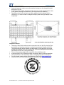
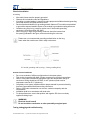
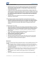
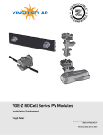
www.etsolar.com Installation | Safety instructions | Maintenance Photovoltaic modules user manual ET Solar series module Please carefully read the following installation and safety instructions. Non-compliance with these instructions may void the module warranty. Purpose of this guide This guide contains information regarding the installation and safe handling of ET Solar photovoltaic modules (hereafter referred to as "modules"). All instructions should be read and understood before attempting installation. If there are any questions, please contact your dealer or ET Solar for further information. The installer should conform to all safety precautions in the guide when installing modules. Before installing a solar photovoltaic system, the installer should become familiar with the mechanical and electrical requirements for photovoltaic systems. Keep this guide in a safe place for future reference. If not otherwise specified, it is recommended that the requirements of the U.S. National Electrical Code (NEC) or respective European Code be followed. General Installing solar photovoltaic systems requires specialized skills and knowledge. The installer assumes all risk of injury, including risk of electric shock. Module installation should be performed only by qualified persons. All modules come with a permanently attached junction box and #12 AWG (4 mm²) wire terminated in Multi Contact PV connectors. Your dealer can provide additional extension cables to simplify module wiring. Each individual module can generate DC voltages greater than 30 volts (V) when exposed to direct sunlight. Contact with a DC voltage of 30 V or more is potentially hazardous. Exercise caution when wiring or handling modules exposed to sunlight. When disconnecting wires connected to a photovoltaic module that is exposed to sunlight, an electric arc may occur. Arcs can cause burns, start fires or otherwise create safety problems. Exercise caution when disconnecting wiring on modules exposed to sunlight. Photovoltaic solar modules convert light energy to direct-current electrical energy, and are designed for outdoor use. Proper design of support structures is the responsibility of the system designer and installer. Modules may be ground mounted, pole mounted, or mounted on rooftops. Do not apply paint or adhesive to the module. When installing modules, observe all applicable local, regional and national codes and regulations. Obtain a building and/or electrical permit where required. Storage Temperature:-10℃~40℃, Storage Humidity:≤70%RH; Use environment temperature:-40~85℃,other use of harsh conditions please indicate. Do not attempt to disassemble the module, and do not remove any attached nameplates or components. Doing so will void the warranty. Do not use mirrors or other hardware to artificially concentrate sunlight on the module. www.ETSolar.com © 2009 ET Solar All Right Reserved -1- www.etsolar.com Safety precautions for installing a solar photovoltaic system Solar modules produce electrical energy when exposed to sunlight. DC voltages may exceed 30V on a single exposed module. Only connect modules with the same rated output current in series. If modules are connected in series, the total voltage is equal to the sum of the individual module voltages. Only connect modules or series combinations of modules with the same voltage in parallel. If modules are connected in parallel, the total current is equal to the sum of individual module or series combination currents. Bypass diodes are preassembled in each module. Do not remove these diodes. Keep children well away from the system while transporting and installing mechanical and electrical components. Completely cover all modules with an opaque material during installation to prevent electricity from being generated. Do not wear metallic rings, watchbands, ear, nose, or lip rings or other metallic devices while installing or troubleshooting photovoltaic systems. Use appropriate safety equipment (insulated tools, insulating gloves, etc) approved for use on electrical installations. Observe the instructions and safety precautions for all other components used in the system, including wiring and cables, connectors, DC-breakers, mounting hardware, inverters, etc. Use only equipment, connectors, wiring and mounting hardware suitable for use in a photovoltaic system. Always use the same type of module within a particular photovoltaic system. Under normal operating conditions, PV modules will produce currents and voltages that are different than those listed in the date sheet. Data sheet values are applicable at standard test data. Short-circuit current and open-circuit voltages should be multiplied by a factor of 1.25 when determining component voltage ratings, conductor ampacity, fuse sizes and size of controls connected to the module or system output. An additional multiplying factor of 125 percent (80 percent de-rating) may be applicable. General installation notes Drainage holes must not be covered with parts of the mounting system. The junction box has a breather port which must be mounted facing downward and cannot be exposed to the rain. The junction box should be on the higher side of the module when it is mounted in order to orient the breather port correctly. Do not lift the module by grasping the module's junction box or electrical leads. Do not stand or step on module. Do not drop the module or allow objects to fall on the module. Do not place any heavy objects on the module. Do not scratch the anodized coating of the frame (except for grounding connection). Do not scratch the glass surface. Prior to installation, do not store modules outdoors or in a damp environment. Inappropriate transport and installation may damage the module glass or frame. www.ETSolar.com © 2009 ET Solar All Right Reserved -2- www.etsolar.com Mechanical Installation Selecting the location Select a suitable location for installation of the module. For optimum performance, the module must be facing true south in northern latitudes and true north in southern latitudes. For detailed information on optimal module orientation, refer to standard solar photovoltaic installation guides or a reputable solar installer or systems integrator. Shading on the module will reduce electricity production. Do not install the module near equipment or in locations where flammable gases can be generated or collected. Selecting the proper mounting structure and hardware Observe all instructions and safety precautions included with the mounting system to be used with the module. Do not drill holes in the glass surface of the module. Doing so will void the warranty. Do not drill additional mounting holes in the module frame. Doing so will void the warranty. Modules must be securely attached to the mounting structure using four mounting points for normal installation. If heavy wind or snow loads are anticipated, additional mounting points should also be used. Please see the drawing below. Load calculations are the responsibility of the system designer or installer. The mounting structure and hardware must be made of durable, anti-corrosion and UV-resistant material. Mounting methods 1. Mounting with Bolts The module must be attached and supported by at least four bolts through the indicated mounting holes. Most installations will use the four inner mounting holes on the module frame(include short frame mounting holes). Depending on the local wind and snow loads, additional mounting points may be required. (e.g. if the snow load is as high as 5400pa, please use eight bolts) 2. Mounting with Clamping Hardware www.ETSolar.com © 2009 ET Solar All Right Reserved -3- www.etsolar.com If module clamps are used to secure the module, the torque on the clamp bolt should be around 8–10 Nm. A minimum of four module clamps should be used, two on each long/short frame side, in the general clamping areas denoted by the wide arrows on the drawing. Depending on the local wind and snow loads, additional module clamps may be required. (e.g. if the snow load is as high as 5400pa, please use eight clamps on the long frame) 3. Zero-Rack modules mounting with Zep Compatible hardwares The array of Zero-Rack modules must be mounted to the roof with Zep Leveling Feet and suitable roof attachment devices to maintain the waterproof integrity of the roof. The system designer and/or installer are responsible for load calculation and proper quantity and locations of the Zep Leveling Feet. Local wind loading and snow loading should be accounted for in the system design. The mounting system design shall comply with all local building codes. A minimum gap of 0.25” between modules is required to allow for thermal expansion. The system must not be immersed in water or constantly exposed to water spray. For more details, please visit the official website of Zep Solar (www.zepsolar.com). Warranty void if non-Zep-certified hardware is attached to groove in module frame. www.ETSolar.com © 2009 ET Solar All Right Reserved -4- www.etsolar.com P660&M660&M572 P672&M672 Zep System I&II , mechanical load up to 5400pa 3. Other Other mounting methods are acceptable as long as the minimum requirement as described under 2. Mounting with clamping hardware are met. www.ETSolar.com © 2009 ET Solar All Right Reserved -5- www.etsolar.com Electrical Installation Grounding All module frames must be properly grounded. Observe all local electric codes and regulations. A bonding or toothed washer is required to make proper and reliable electrical grounding connection with the anodized aluminum frame. Devices listed and identified for grounding metallic frames of PV modules are permitted to ground the exposed metallic frames of the module to grounded mounting structures. Consider using a lay-in lug, rated for outdoor use, if the module grounding conductor is to be larger than #10 AWG. When using lay-in lugs, the grounding conductor should be inserted into the opening indicated in the figure, and secured using the set screw. Please use our recommended grounding method below on the long frame when the modules are used in salty environment. PV module grounding with lay in lug (φ4mm grounding holes) General electrical installation Do not use modules of different configurations in the same system. This module is supplied with Multi Contact connectors for electrical connections. Refer to local code to determine appropriate types and temperature ratings of conductors. Wiring should be #12 AWG, 4 mm²(minimum) and must be temperature rated at 90 °C (minimum). Completely cover system modules with an opaque material to prevent electricity from being generated while disconnecting conductors. Refer to local code to determine over current, conductor ampacity and size requirements. Installation shall be in accordance with local code. For best performance, ensure that positive and negative DC wires run closely together avoiding loops. WARNING! Electrical shock hazard! Do not touch bare conductors or other potentially energized parts. Testing, debugging and troubleshooting www.ETSolar.com © 2009 ET Solar All Right Reserved -6- www.etsolar.com Blocking diode can be used in PV system to prevent reverse current from the battery if there is no photo current in the module. If charge controllers are not used, then it is recommended to use blocking diodes. For more details on charge controllers, please consult with professionals. In cases where two or more modules are connected serially in a system, if part of the modules are occluded and the other part are exposed to the sun, the high reverse current will flow partially or completely through the module, causing the modules to overheat and even damaging the modules. Bypass diode used in modules can protect modules from such impact of excessive reverse current.. The bypass diodes have been integrated in the junction box. Operators should protect themselves from electrical shock during debugging or maintenance of solar systems. Test procedure for modules serial connected before connect them to the PV system. Use digital multimeter to check the total open circuit voltage of the serially connected modules. The results should be equal to the sum of the open circuit voltage of individual modules, which can be found from the label on the modules. If the total open circuit voltage is much lower than expected, please follow the following procedure in this instruction. Troubleshooting for low voltage There are two causes of low open circuit voltage, environmental change or circuit fault. The drop of irradiance or increase of environmental temperature reduces the open circuit voltage, which is normal. The troubleshooting here refers to the low voltage caused by circuit faults, which is usually due to incorrect connection of terminals or damage of bypass diodes. First, check all wiring connections, and ensure they are well-connected.into the PV system. Then check the modules each by each as below: Measure the open circuit voltage of a module. Cover the module completely with opaque material. Disconnect the module from the system. Remove the opaque material from the module, and measure its open circuit voltage. If the measured voltage is one third or two thirds of the rated value, it indicates that bypass diodes were broken,and should be replaced. Maintenance ET Solar recommends the following maintenance items to ensure optimal performance of the module: Clean the glass surface of the module as necessary. Use water and a soft sponge or cloth for cleaning. A mild, non-abrasive cleaning agent can be used if necessary. Do not use dishwasher detergent. Do not have water staying on the glass surfaces of PV modules for a long time. If a module power decreases abnormally, and its glass surface is found covered by dust, please contact your module installer, retailer or ET solar immediately for technical support. Do not attempt to clean a module if the front glass is broken or the backsheet is perforated. Electrical and mechanical connections should be checked periodically by qualified www.ETSolar.com © 2009 ET Solar All Right Reserved -7- www.etsolar.com personnel to verify that they are clean, secure and undamaged. Check the electrical and mechanical connections periodically to verify that they are clean, secure and undamaged. Problems should only be investigated by qualified personnel. Observe the maintenance instructions for all other components used in the system. Shutting down the system Completely cover system modules with an opaque material to prevent electricity from being generated while disconnecting conductors. Disconnect system from all power sources in accordance with instructions for all other components used in the system. The system should now be out of operation and can be dismantled. In doing so, observe the all safety instructions as applicable to installation. Electrical ratings of the concerned modules: Pls refer to each kinds of ET module datasheet. Disclaimer of liability Because the use of this manual and the conditions or methods of installation, operation, use and maintenance of photovoltaic products are beyond ET Solar's control, ET Solar does not accept responsibility and expressly disclaims liability for loss, damage, or expense arising from or in any way connected with improper installation, operation, use or maintenance . Improper installation, operation, use or maintenance means that installation, operation, use or maintenance does not strictly follow this manual and/or the local, regional and national codes and regulations. ET Solar shall not be any way responsible or liable for natural causes, including but not limited to normal wear and tear of photovoltaic products, the natural effects of exposure to weather conditions over time and the outdoor dust build-up. ET Solar shall not be in any way responsible or liable for the end user Customer or any third-party arising out of any non-performance or delay in performance of any terms and conditions of sale, including this manual, due to fire, flood, blizzard, hurricane, thunder, acts of God, changes of public policies, terrorism, war, riots, strikes, unavailability of suitable and sufficient labor or materials and other events which are out of control of ET Solar. No responsibility is assumed by ET Solar for any infringement of patents or other rights of third parties, which may result from use of the PV product. No license is granted by implication or otherwise under any patent or patent rights. The information in this manual is based on ET Solar's knowledge and experience and is believed to be reliable, but such information including product specification (without limitations) and suggestions does not constitute a warranty, expressed or implied. ET Solar reserves the right to change the manual, the product, the specifications, or product information sheets without prior notice. www.ETSolar.com © 2009 ET Solar All Right Reserved -8- www.etsolar.com Information about manufacturer: ET Solar China 27F, Galaxy International Plaza, 7 Shanxi RD, Nanjing 210009, China Tel: 86 25 86898096 86898098 Fax: 86 25 86898097 E-mail: [email protected] Please consult your dealer or the manufacturer concerning the warranty of your modules. If you have any further questions, your dealer and ET Solar will gladly assist you. Subject to technical modifications without notice. 2009 © ET Solar Group. www.ETSolar.com © 2009 ET Solar All Right Reserved -9-